the Creative Commons Attribution 4.0 License.
the Creative Commons Attribution 4.0 License.
 | 13 Feb 2024
Sliding mode control of electro-hydraulic servo system based on double observers
Xiaoyu Su
Xinyu Zheng
In this paper, in order to solve the real-time state value acquisition and external-disturbance problems faced during the working process of an electro-hydraulic servo system, a sliding mode controller based on dual observers is designed, which enables the system to effectively acquire the state value and realize better control accuracy. The method uses a high-gain observer to obtain the system state in real time and then adds a perturbation observer to provide more accurate state and perturbation observations for the sliding mode controller. The dual observer observes the obtained states and external perturbations and feeds these back to the sliding mode controller to control the system accurately. Finally, the observation performance of the observers is verified by comparative simulation, and the proposed control method can improve the control accuracy.
- Article
(652 KB) - Full-text XML
- BibTeX
- EndNote


Electro-hydraulic servo systems are widely used in industrial automation control for various applications such as in hydraulic robots (Huang et al., 2019; Q. Guo et al., 2015), vehicle suspension systems (Pan and Sun, 2018), aerospace (Tang et al. 2021), machine tool tables, ship rudders and other applications (Nguyen et al. 2021) due to their high control accuracy, fast response time and high output power. The electro-hydraulic servo system is a typical non-linear system, which contains many non-linear characteristics and problems such as modelling uncertainties and external disturbances. These problems will make it challenging to improve the control accuracy of electro-hydraulic servo systems.
To solve the above problems, modern control methods are applied in electro-hydraulic servo systems, such as adaptive control (Shen and Shen, 2021; Wos and Dindorf, 2013; Ren and Gong, 2017; Feng and Yan, 2020; Feng et al., 2022), backstepping control (Yang et al., 2017; Ji et al., 2021; Kim et al., 2010), H-∞ control (Q. Guo et al., 2015; Milić et al., 2010), or sliding mode control (Tang and Zhang, 2011). In practical engineering scenarios, electro-hydraulic servo systems need to work with high precision and a fast response in the face of high rotational accuracy, complex structures, loads and other external disturbances. Among the many non-linear control methods, the sliding mode controller mainly uses its strong robustness to achieve trajectory tracking; robustness can give the system good control effect in the cases of non-linearity, modelling uncertainty or being subject to external disturbances. Therefore, the sliding mode controller is suitable for solving the control problems of electro-hydraulic servo systems.
In order to integrate modern control methods into electro-hydraulic servo systems in practical engineering, all state quantities need to be measured and fed back. However, the need for multiple sensors for full condition monitoring and feedback means that the cost of control systems in complex industrial environments is increased, and the reliability of the system is reduced. Therefore, considering the complex environment of the engineering site, state observers are a reliable option. In recent years, a variety of state observers have been used to observe the state values of a system for controller design. In order to solve the system state value acquisition and tracking-error problems, Shen et al. (2017) used an ESO (extended state observer) to realize robust control without velocity and pressure measurements and introduced a finite-time design method to achieve tracking-error convergence in finite time. Won et al. (2017) proposed an integral sliding mode control method based on a high-gain observer used to estimate the velocity and load pressure and to effectively feed back to the controller to achieve position tracking. Du et al. (2021) proposed a high-gain-observer-based output feedback integral sliding mode control to solve electro-hydraulic servo system control problems. Lin et al. (2020) proposed the use of an adaptive control scheme based on a high-gain observer to realize state value observations and to perform adaptive position tracking. Cheng et al. (2020) proposed a sliding mode state observer to obtain state estimates of velocity and pressure, and a new second-order sliding mode controller approach was used to control the system to improve accuracy. Palli et al. (2020) use an adaptive higher-order sliding mode observer to estimate the state of the system, which improves the speed of convergence of the observation error and limits the observer gain in the presence of noisy measurements. Due to the presence of external loads and disturbances in industrial controls, this leads to system instability and loss of accuracy. The state observer can only observe the system state, and even extended observer observations cannot observe external load and disturbance observations.
Therefore, in industrial sites, there are complex environmental disturbances to the system, and it is important to obtain and compensate for these external disturbances. K. Guo et al. (2015) proposed a non-linear cascade controller based on an extended-perturbation observer for tracking a given signal in the presence of external perturbations and parameter uncertainties. An active-disturbance-suppression control method was proposed by Nguyen et al. (2021) to improve the position-tracking performance of electro-hydraulic drive systems in the presence of parametric uncertainty, non-parametric uncertainty and external disturbances. Two extended state observers were constructed by Yao and Deng (2017) to estimate matching uncertainty and mismatching uncertainty, respectively, and to perform compensating control in the backstepping controller. Sun et al. (2018) proposed a non-linear robust motion controller based on an extended-perturbation observer for observing and compensating for the disturbance, and the results showed that the controller has a good transient response. However, because the design process of the disturbance observer described above requires that the state values of the system be obtained, sensors are used to obtain the status values of the system; this means an increase in the cost and complexity of the control system.
Based on the above analysis, the control accuracy of the electro-hydraulic servo system depends on obtaining the state value and disturbance value effectively and compensating for them. This paper uses a high-gain observer and an interference observer to obtain state values and external disturbance, and a law sliding mode controller is designed based on the estimated values for real-time compensation control and improved tracking performance. The double observers obtain the system state and external disturbances in real time and feed them back to the controller, which effectively replaces the function of sensors and reduces the cost and complexity of the actual system. The sliding mode controller is designed based on observations and taking observation errors into account. Finally, comparative simulations are presented to demonstrate the improvement in the control accuracy of the control method.
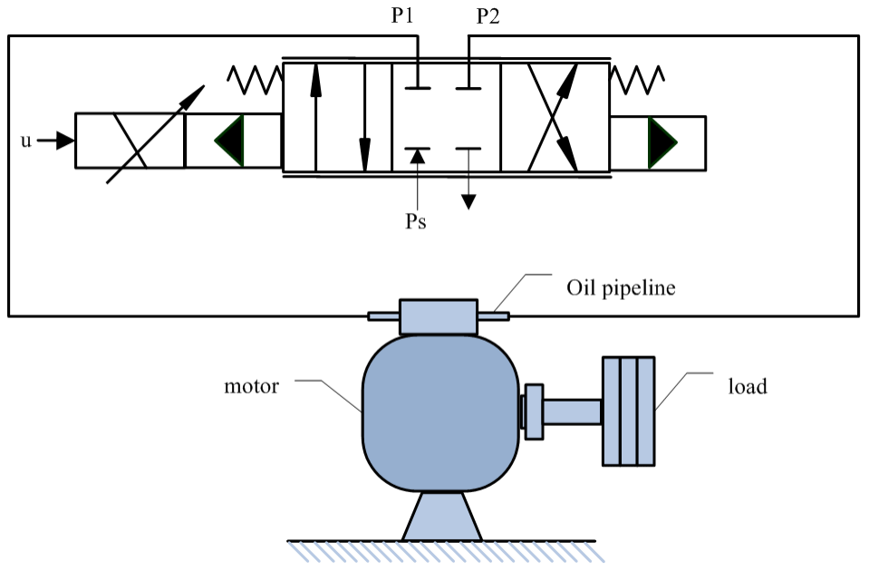
The structure of the electro-hydraulic position servo system is shown in Fig. 1. According to Newton's second law, the force balance equation of the load can be obtained as
where J is the rotational inertia of the motor, Dm is the displacement of the hydraulic motor, θ is the angle of rotation of the valve motor, is the hydraulic-motor load pressure, P1 and P2 are the hydraulic-motor two-cavity pressure, B is the coefficient of viscous friction, and D is the external disturbing force.
The hydrodynamic model of the servo valve is non-linear, there is a mathematical relationship between the output of the load flow, and the spool displacement can be expressed as follows:
where Cd is the servo valve orifice flow coefficient, ω is the servo valve throttle area gradient, xv is the movement of the servo valve spool, Ps is the pressure of the fluid, and τ is the density of the fluid.
The sgn function is defined as
The equation of continuity between the flow of the load and the flow of the hydraulic oscillating motor is
where Ct is the total leakage coefficient of the hydraulic motor, V is the total volume of the two chambers connected to the main pipe, βe is the effective volume elastic modulus, and q(t) is the time-varying uncertain flow in the servo system.
The servo valve operates at a much higher frequency than the hydraulic oscillating motor. To simplify the relationship between the motor and the servo valve, the dynamics of the servo valve can be simplified to a proportional relationship:
Then Eq. (2) can be expressed as
where .
To simplify controller design, the system state variable is chosen as follows: . According to Eqs. (1)–(6), the state space form of an electro-hydraulic servo system can be expressed as follows:
According to Eqs. (7)–(8), the system can be written as follows:
where ,, ,, , , .
According to the working principle of the electro-hydraulic servo system and the characteristics of the system, the following reasonable assumptions have been made in order to facilitate the controller design.
-
The pressure in each chamber of the hydraulic rotary motor is equal everywhere.
-
External disturbances are bounded, and D≤Dmax.
3.1 Design of the double observers
The design of controllers in practical engineering requires the use of real-time data on system state quantities and external disturbances. In order to reduce the cost and improve the stability of the system, observers were chosen to replace the function of sensors in the system. In this paper, a high-gain observer and a disturbance observer are used to observe the system state and external disturbances, and the obtained estimates are fed back to the controller in real time.
The observer estimates other state values from the feedback provided by the angle of rotation, and the specific high-gain observer design is
The above equation is written in simplified form as follows:
where is the estimate of state variables, ; ; and , , where α1, α2, α3 and ε are all greater than 0.
It is shown by Eq. (10) that needs to be obtained before estimate of the system state can be obtained. Therefore, the non-linear disturbance observer (NDO) is designed.
The auxiliary variable z is introduced (Zhang, 2019):
where γ is the design parameter for the NDO, and γ>0.
According to Eqs. (7) and (13), the following can be obtained:
Estimates of the auxiliary variable are designed to be used in the estimation of disturbance value perturbations:
According to Eqs. (14) and (15), the following can be obtained:
3.2 Stability of the double observers
We define the error of the state observer as
Simplifying Eq. (17) yields
Equation (18) can be expressed as
where , , , , , and .
The equation of state for the observation error can be obtained as follows:
We make the matrix a Hurwitz matrix by choosing the appropriate parameter α1, α2, or α3; then there exists a positive definite matrix P and any given symmetric definite matrix Q, satisfying
Since the coefficients before the state variables in Eq. (7) are obtained from the individual parameters of the electro-hydraulic servo system, it can be assumed that .
The Lyapunov equation defining the observer is
Taking the derivative of Eq. (22) yields
According to Eqs. (17)–(22), it can be deduced that
Let Gi=∥PBi∥, and from the fundamental inequality we get ; then Eq. (24) can be reduced to
We let +2εγ G1 +2 G2(μ2 + μ3) +2G2μ4 |u|max|η3|]. |u|max be the maximum output of the controller so that , ; this can be simplified to get
Let the positive definite matrix , . Eq. (26) can be reduced to:
where , λmax(⋅), and λmin(•) refers to the maximum and minimum eigenvalues of the matrix.
The solution to the inequality (27) can be expressed as
When t→∞, we can get . Thus, it can be obtained that Vo is exponentially convergent; then, the systematic observation error is bounded (Yang and Yao, 2019).
4.1 Controller design
The design of the slide controller can be divided into two steps, including the design of the slide surface and the design of the control law.
Defining the electro-hydraulic position servo system position tracking error e, velocity tracking error , acceleration tracking error and acceleration derivative tracking error e, θd is the given signal; according to Eqs. (2)–(7), these can be expanded separately to obtain
Defining the slide surface of the controller, we get
where .
According to the law of exponential convergence,
The exponential-convergence law sliding mode controller based on the dual observer can be designed as follows:
where , , β and k are the gain of the controller discontinuity term, and β>0 and k>0; .
Based on this controller, the sliding surface of the system can be made to converge to zero, and finally, the system reaches a steady state.
4.2 System stability analysis of sliding mode control
Based on the stability analysis of the system in control theory, the Lyapunov function is defined as follows:
Because the small observer error can be obtained (), the derivative of Eq. (36) gives
where Δ1 is the controller error caused by the observer error.
We let ; its value depends on the value of the observation error for each state.
Then Eq. (37) can be reduced to
We let , and ; then Eq. (38) can be expressed as
According to the inequality, Eq. (39) can be solved as
When t→∞, we can get . Then the system will reach a steady state.
To verify the proposed control strategy, a simulation model of the system was built in MATLAB–Simulink, and the simulation step size was set to 0.001 s. Due to the limited voltage, current and control torque that can be applied to each structure of the electro-hydraulic servo system in practical engineering, exceeding the maximum load can cause damage to the machine's components and then limit the controller output in the simulation to between .
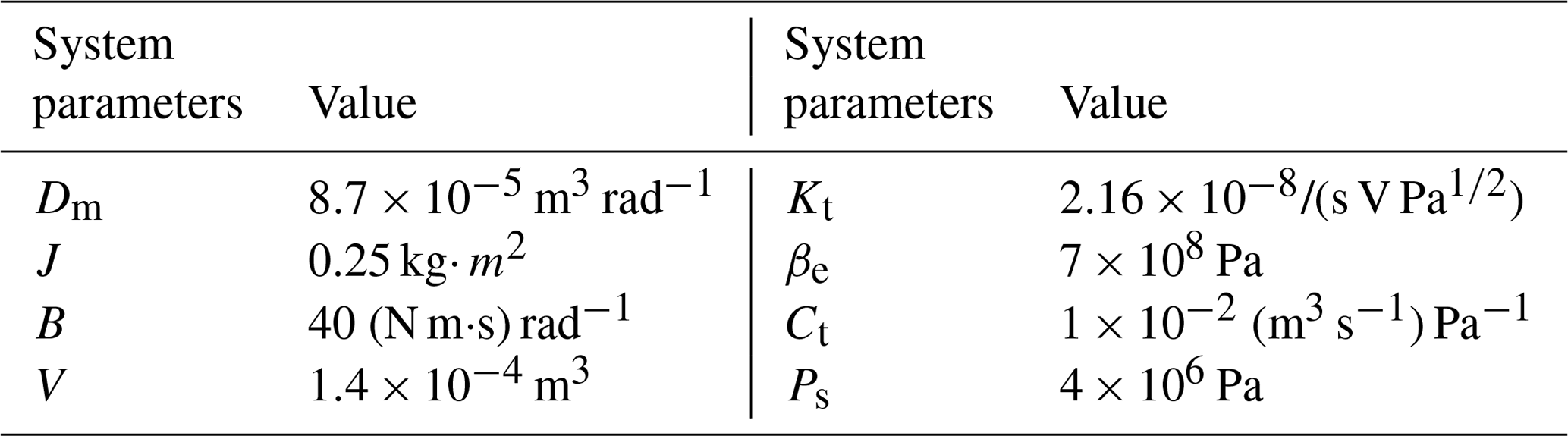
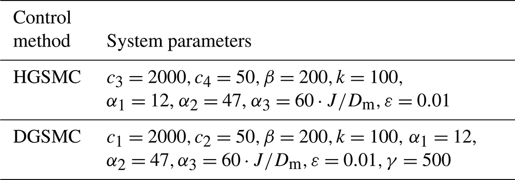
The parameters of the hydraulic system and the controller parameters are outlined in Table 1.
To verify the effectiveness of the designed control method, comparative simulation experiments are carried out. We select the given tracking signal as . The high-gain-observer-based sliding mode controller (HGSMC) is simulated and compared with the dual-observer-based sliding mode controller (DGSMC) in this paper. To effectively assess control performance, the ITAE (integrated time and absolute error) metric, which represents the accumulation of system tracking errors, is used to show the improvement in control accuracy.
Since there is no interference observer, such that the interference value of input to the HGSMC controller is 0, this means that the interference cannot be compensated in the controller. The controller is designed as .
The high-gain observer can effectively observe the system state under no-load or light-load conditions to obtain and achieve a small observation error and then feed back to the controller for compensation to improve the system control accuracy. However, in many operating environments, hydraulic equipment may need to drive large loads or face external disturbances. In order to better match the actual working conditions, two working conditions, I ( and II (, are used for the analysis in the comparative simulation.
Working condition I
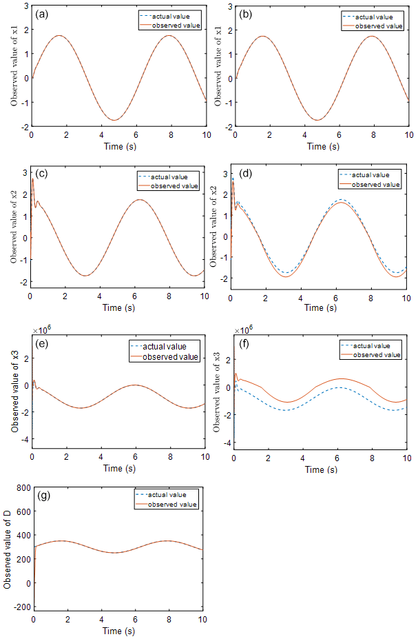
Figure 2Observation effect diagram of a single observer (b, d, f) and a double observer (a, c, e, g).
Figure 2 shows the state observations obtained by the observer during the control process of condition I for both the HGSMC and DGSMC methods. It can be seen from the figure that, when the external load is large, the high-gain observer alone will produce observation error, where the trend of x2 and x3 observations is basically the same as the actual value, but the observation error at the peak point is large. These deviations in the observed values are substituted into the sliding mode controller, resulting in deviations in the output of the sliding mode controller from the desired control output of the system. However, the relatively short adjustment time of the interference observer in the dual observer for the observation of external disturbances indicates that the adjustment is fast and can track the disturbance values well after a short fluctuation. This provides a state value for the high-gain observer and makes the structure of the observer more complete.
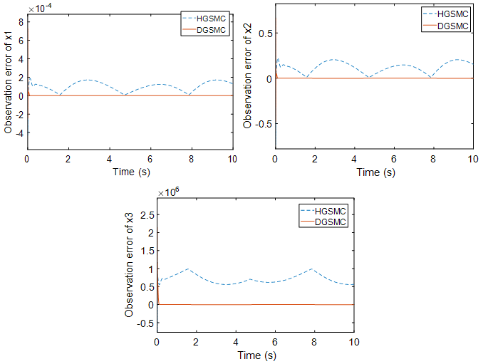
Figure 3 shows a comparison of the observation errors of the observer for the system state values for the two control methods. It can be clearly seen that the observation errors of HGSMC for x2 and x3 are larger than those of DGSMC. The larger the observation error is, the larger the feedback error to the controller, resulting in the controller being unable to accurately compensate for the tracking error.
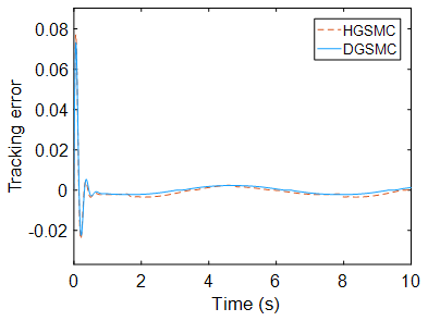
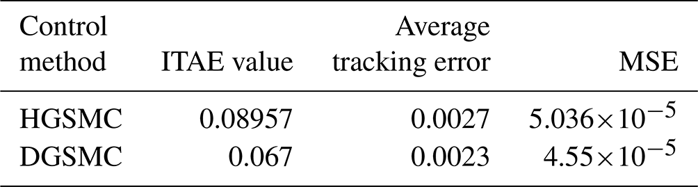
Figure 4 shows the tracking error of the two control methods, from which it can be seen that the control overshoot of the two-observer-based sliding mode controller is smaller than that of the high-gain-observer-based sliding mode controller, and the regulation time is almost the same. The steady-state error under HGSMC control is , while the steady-state error of the DGSMC is , which is reduced compared with the former. DGSMC also improves by 25.2 % over HGSMC in terms of accumulation of errors. This shows that the dual observer can bring the effective state observation support to the sliding mode controller in the presence of external disturbance, and the combination of the two can improve the control accuracy of the system.
Working condition II
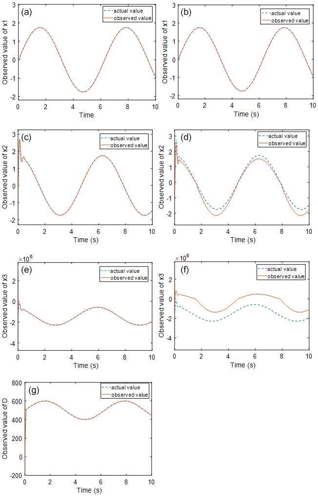
Figure 5Observation effect diagram of a single observer (b, d, f) and a double observer (a, c, e, g).
Figure 5 shows the state observations obtained by the observer during the control process of condition II for both the HGSMC and DGSMC methods. It can be observed that the situation is the same as that in working condition I: the deviation of x2 at the peak point and the trend of x3 are basically the same, but the observation error is large, and when the external disturbance increases, the observation error also increases further because the external-disturbance value is not added to the high-gain observer for observation operation. The difference between the actual and observed values of x2 and x3 becomes larger. This will cause the output of the sliding mode controller to deviate more from the actual required output, which will further reduce the control accuracy of the system.
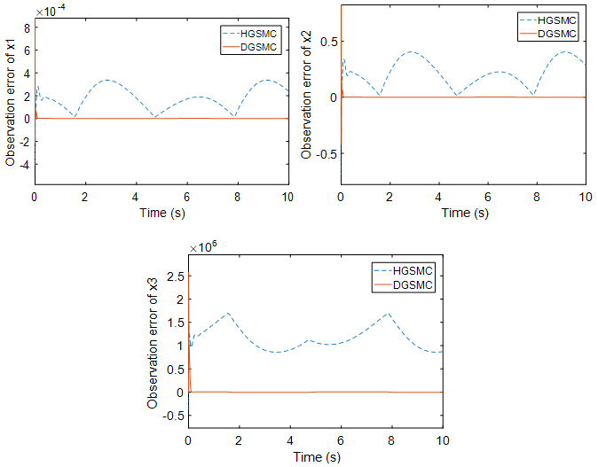
Figure 6 shows the comparison of the observation error of the system state values with the observers of the two control methods. Comparing with Fig. 3, it can be found that the observation error of the single observer for the state quantities also increases when the external load disturbance is greater, while the observation error of the dual observer can still maintain a small error range.
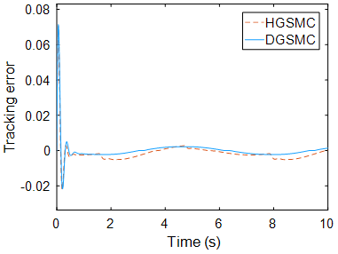
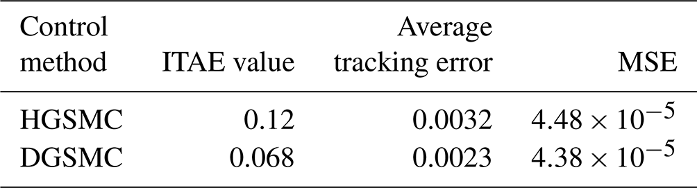
Figure 7 shows the comparison of the tracking error of the two controllers, from which it can be seen that the system regulation time under the two controllers is basically the same, but the sliding mode controller is based on the high-gain observer, the system steady-state error of HGSMC is after reaching stability, and the tracking error increases with the increase in load disturbance compared with working condition I. In contrast, the steady-state error of the system under DGSMC control remains at , which still provides high control accuracy for the system. Compared with working condition I, the disadvantage of having only one state observer is more obvious as the external disturbance increases, and the failure to observe the disturbance and compensate for the high-gain observer will increase the observation error, which will bring about insufficient controller output of the sliding mode controller and eventually lead to the output curve deviating farther from the given curve and further degrading the control accuracy.
In this paper, a sliding mode controller based on a dual observer is proposed to control the electro-hydraulic servo system. The double observers are designed to obtain the observed and disturbed values and to compensate for them in relation to the controller in real time. Based on the observed state and external-disturbance value, it has good robustness and effectively controls the non-linearity of the electro-hydraulic servo system, and the stability of the system is proved. The simulation results show that the above control method can observe the state and disturbance values in the presence of external load disturbance, and compensate the disturbance by using with the sliding mode controller, which effectively improves the control accuracy and stability of the electro-hydraulic servo system.
We experimentally verified the sliding mode controller based on a high-gain observer, and the results of the experiment showed that the method can effectively control the hydraulic valve-controlled motor. However, the method proposed in this paper cannot be experimentally verified because the laboratory is not able to meet the experimental conditions for the time being. The future research direction can be in the direction of energy saving.
No data sets were used in this article.
XS is the main author of the paper, guiding the concepts and methods, and proofreading and revising the paper. XZ wrote the draft.
The contact author has declared that none of the authors has any competing interests.
Publisher's note: Copernicus Publications remains neutral with regard to jurisdictional claims made in the text, published maps, institutional affiliations, or any other geographical representation in this paper. While Copernicus Publications makes every effort to include appropriate place names, the final responsibility lies with the authors.
This paper was edited by Daniel Condurache and reviewed by Weichao Sun and four anonymous referees.
Cheng, C., Liu, S. Y., and Wu, H. Z.: Sliding mode observer-based fractional-order proportional–integral–derivative sliding mode control for electro-hydraulic servo systems, P. Institut. Mechan. Eng. Part C, 234, 1887–1898, https://doi.org/10.1177/0954406220903337, 2020.
Du, H., Shi, J. J., Chen, J. D., Zhang, Z. Z., and Feng, X. Y.: High-gain observer-based integral sliding mode tracking control for heavy vehicle electro-hydraulic servo steering systems, J. Mechatronics, 74, 102484, https://doi.org/10.1016/j.mechatronics.2021.102484, 2021.
Feng, L. J. and Yan, H.: Nonlinear adaptive robust control of the electro-hydraulic servo system, J. Appl. Sci., 10, 4494, https://doi.org/10.3390/app10134494, 2020.
Feng, H., Song, Q. Y., Ma, S. L.,Ma, W., Yin, C. B., Cao, D. H., and Yu, H. F.: A new adaptive sliding mode controller based on the RBF neural network for an electro-hydraulic servo system, J. ISA Trans., 129, 472–484, https://doi.org/10.1016/j.isatra.2021.12.044, 2022.
Guo, Q., Yu, T., and Jiang, D.: Robust H∞ positional control of 2-DOF robotic arm driven by electro-hydraulic servo system, J. ISA Trans., 59, 55–64, https://doi.org/10.1016/j.isatra.2015.09.014, 2015.
Guo, K., Wei, J. H., Fang, J. H., Feng, R. L., and Wang, X. C.: Position tracking control of electro-hydraulic single-rod actuator based on an extended disturbance observer, Mechatronics, 27, 47–56, https://doi.org/10.1007/s11771-015-2740-2, 2015.
Huang, Y. Z., Pool, D. M., Stroosma, O., and Chu, Q. P.: Long-stroke hydraulic robot motion control with incremental nonlinear dynamic inversion, IEEE/ASME Trans. Mechatron., 24, 304–314, https://doi.org/10.1109/TMECH.2019.2891358, 2019.
Ji, X. H., Wang C. W., Zhang, Z. Y., Chen, S., and Guo, X. P.: Nonlinear adaptive position control of hydraulic servo system based on sliding mode back-stepping design method, J. Proceedings of the Institution of Mechanical Engineers, Part I: J. Syst. Control Eng., 235, 474–485, https://doi.org/10.1177/0959651820949663, 2021.
Kim, H. M., Park, S. H., Song, J. H., and Kim, J. S.: Robust position control of electro-hydraulic actuator systems using the adaptive back-stepping control scheme, J. Proceedings of the Institution of Mechanical Engineers, Part I: J. Syst. Control Eng., 224, 737–746, https://doi.org/10.1243/09596518JSCE980, 2010.
Lin, F., Ou, K., and Wang, Y. X.: A Position Adaptive Control Associated with High Gain Observer for Electro-Hydraulic Servo System, 2020 Chinese Automation Congress (CAC), IEEE, https://doi.org/10.1109/CAC51589.2020.9327275, 2020.
Milić, V., Šitum, Ž., and Essert, M.: Robust H∞ position control synthesis of an electro-hydraulic servo system, J. ISA Trans., 49, 535–542, https://doi.org/10.1016/j.isatra.2010.06.004, 2010.
Nguyen, M. H., Dao, H. V., and Ahn, K. K.: Active Disturbance Rejection Control for Position Tracking of Electro-Hydraulic Servo Systems under Modeling Uncertainty and External Load, Actuators, 10, 20, https://doi.org/10.3390/act10020020, 2021.
Palli, G., Strano, S., and Terzo, M.: A novel adaptive-gain technique for high-order sliding-mode observers with application to electro-hydraulic systems, J. Mechan. Syst. Signal Process., 144, 106875, https://doi.org/10.1016/j.ymssp.2020.106875, 2020.
Pan, H. H. and Sun, W. C.: Nonlinear output feedback finite-time control for vehicle active suspension systems, J. IEEE Trans. Indust. Informatics, 15, 2073–2082, https://doi.org/10.1109/TII.2018.2866518, 2018.
Ren, H. P. and Gong, P. F.: Adaptive control of hydraulic position servo system using output feedback, J. Proceedings of the Institution of Mechanical Engineers, Part I: Journal of Systems and Control Engineering, 231, 527–540, https://doi.org/10.1177/0959651817708487, 2017.
Shen, W. and Shen, C.: An extended state observer-based control design for electro-hydraulic position servomechanism, Control Eng. Practice, 109, 104730, https://doi.org/10.1016/j.conengprac.2021.104730, 2021.
Shen, G., Zhu, Z. C., Zhao, J. S., Zhu, W. D., Tang, Y., and Li, X.: Real-time tracking control of electro-hydraulic force servo systems using offline feedback control and adaptive control, J. ISA Trans., 67, 356–370, https://doi.org/10.1016/j.isatra.2016.11.012, 2017.
Sun, C. G., Fang, J.. H., Wei, J. H., and Hu, B.: Nonlinear motion control of a hydraulic press based on an extended disturbance observer, J. Ieee Access., 6, 18502–18510, https://doi.org/10.1109/ACCESS.2018.2813317, 2018.
Tang, R. and Zhang, Q.: Dynamic sliding mode control scheme for electro-hydraulic position servo system, J. Proc. Eng., 24, 28–32, https://doi.org/10.4028/www.scientific.net/AMR.798-799.598, 2011.
Tang, W. B., Xu, G. C., Zhang, S. J., Jin, S. F., and Wang, R. X.: Digital Twin-Driven Mating Performance Analysis for Precision Spool Valve, Machines, 9, 157, https://doi.org/10.3390/machines9080157, 2021.
Winnicki, A. and Olszewski, M.: Sliding Mode Control of electro-hydraulic servo system, J. Pomiary Automatyka Kontrola, 55, 174–177, 2009.
Won, D., Kim, W., and Tomizuka, M.: High-gain-observer-based integral sliding mode control for position tracking of electrohydraulic servo systems, IEEE/ASME Trans. Mechatron., 22.6, 2695–2704, https://doi.org/10.1109/TMECH.2017.2764110, 2017.
Wos, P. and Dindorf, R.: Adaptive control of the electro-hydraulic servo-system with external disturbances, J. Asian J. Control, 15, 1065–1080, https://doi.org/10.1002/asjc.602, 2013.
Yang, G. C. and Yao, J. Y.: Output feedback control of electro-hydraulic servo actuators with matched and mismatched disturbances rejection, J. J. Franklin Institute, 356, 9152–9179, https://doi.org/10.1016/j.jfranklin.2019.07.032, 2019.
Yang, X., Zheng, X. L., and Chen, Y. H.: Position tracking control law for an electro-hydraulic servo system based on backstepping and extended differentiator, J. IEEE/ASME Trans. Mecha., 23, 132–140, https://doi.org/10.1109/TMECH.2017.2746142, 2017.
Yao, J. Y. and Deng, W. X.: Active disturbance rejection adaptive control of hydraulic servo systems, J. IEEE Trans. Indust. Electro., 64, 8023–8032, https://doi.org/10.1109/TIE.2017.2694382,2017.
Zhang, J. J.: State observer-based adaptive neural dynamic surface control for a class of uncertain nonlinear systems with input saturation using disturbance observer, J. Neural Comput. Appl., 31, 4993–5004, https://doi.org/10.1007/s00521-018-03993-x, 2019.
- Abstract
- Introduction
- Modelling of electro-hydraulic servo system
- Design and stability proof of double observers
- Design of sliding mode controller based on double observers
- Simulation analysis
- Conclusions
- Data availability
- Author contributions
- Competing interests
- Disclaimer
- Review statement
- References