the Creative Commons Attribution 4.0 License.
the Creative Commons Attribution 4.0 License.
Serial–parallel cooperative assembly approach for precision micro-assembly of axial holes
Lisong Dong
Jie Ma
Jiesheng Cao
Daoming Wang
The assembly of high-density axial holes represents a crucial step in integrating highly sophisticated components for electronic equipment. This process faces two primary challenges: stringent precision requirements and the need for robust control during delicate adjustments. Given the miniaturization of components, manual assembly becomes inefficient. To address these challenges, this study introduces a novel dual-robot assembly system. The system incorporates a serial robot for force-controlled compliant assembly of precision axial holes, leveraging joint force sensors for direct force-feedback control to ensure enhanced positional accuracy. Additionally, a parallel robot facilitates precise positional adjustments, with its positioning accuracy further refined through kinematic calibration techniques validated through rigorous simulations. Ultimately, the established dual-robot assembly experimental platform successfully demonstrated the precision assembly of high-density axial holes, offering robust technical support for the precise integration of highly integrated components in electronic equipment.
- Article
(3833 KB) - Full-text XML
- BibTeX
- EndNote
The radar antenna array comprises multiple antenna subarrays, wherein the digital transmitter/receiver (T/R) modules within an individual antenna subarray serve as the pivotal components. The installation process of these T/R modules typically necessitates intricate precision axial-hole assembly, a complex sequence of steps that, coupled with the high-density layout of components, poses stringent demands on assembly efficiency (Yin et al., 2022; Tian et al., 2023; Chen et al., 2021). However, in the manual assembly process, professional skills and high labor costs are required (Zhao et al., 2020). Compared with manual assembly, robotic assembly has the advantages of large load capacity, high precision, and good repeatability, and replacing manual assembly with robots in the actual production process can significantly improve productivity and reduce costs (Zhang et al., 2022; Zhao et al., 2023).
The T/R module is easily damaged and require high accuracy during automated robot assembly, which requires good accuracy and flexibility of the robot assembly system (T. Jiang et al., 2020). Therefore, scholars have attempted to improve these two critical properties in various ways. Gai et al. (2021) proposed a feature-based flexural control method, which can accomplish gap or interference fits for different cylindrical or prismatic objects; however, it is more complex and does not improve the assembly efficiency significantly when compared to the existing model-based methods. Ti et al. (2022) proposed a dynamic constraint based on the dynamic motion primitive (DCDMP) method to generalize motion under variable constraint conditions and used radial basis function (RBF) networks to improve the accuracy of assembly force and torque prediction. However, the imitation learning-based assembly strategy presented in the paper is not applicable to precision assembly. Unten et al. (2023) utilized the transient force information of a shaft in two-point contact with a hole to estimate the orientation of the hole and improved the assembly efficiency by deriving the attitude of the shaft at the time of two-point contact. However, the method is not suitable for precision assembly when the initial position of the shaft is out of a certain range. Lee et al. (2022) devised a contact state (CS) estimation method that includes a torque indicator, a position/speed indicator, and a CS discriminator to estimate the contact state of the axial-hole assembly process. However, the method did not implement feature selection or transformation algorithms and was computationally intensive, resulting in inefficient assembly. Li et al. (2023) proposed an equivalent axial hole model and a corresponding assembly framework for solving the robot multi-axis hole entry problem. An instantaneous center of rotation controller and a variable angular velocity controller were designed to improve force tracking performance, assembly stability, and speed; nevertheless, the framework is not applicable to elastic parts with interference fits. Choi et al. (2023) developed a pliable compensator that can measure six-axis forces, torques, and displacements, which can provide the information needed for feedback control and protect the robot from shocks. They also proposed a displacement-based misalignment compensation method for shaft-hole assembly in conjunction with the proposed device; however, this method is only suitable for larger workpieces rather than high-density small-size shaft-hole assembly. Zhang et al. (2023) used a flexible gripper fitted with a soft damper to perform the task of assembling shaft holes with large deviations; however, due to stiffness issues, the gripper is not suitable for precision assembly of small parts. Although various methods and techniques have been used in the above studies to improve the accuracy and flexibility of robotic axial-hole assembly systems, they still suffer from limitations such as low assembly efficiency, inapplicability to high-density axial-hole assemblies, and the basic idea is to complete the gripping and assembly of parts by tandem robots.
Serial robots are characterized by a large workspace and flexible attitude control and can adapt to diverse operational tasks and work environments. However, they suffer from shortcomings such as slow response speed and limited load capacity. With the increase in the number of joints, the error gradually accumulates, leading to a decrease in the positioning accuracy and stability of the end effector (H. H. Sun et al., 2020; Kumar et al., 2020; Niu et al., 2020). In contrast, parallel robots have the advantages of high stability, fast response, and high accuracy (Song et al., 2024), which are very suitable for precision operations (Lilge et al., 2024; Chu et al., 2022; Wang et al., 2023). At the same time, parallel robots have a small workspace and are inappropriate for large-scale operations (Russo et al., 2024). Because of these, this paper designs a collaborative serial–parallel robot assembly system for high-density precision shaft-hole assembly. The serial robot carries out the initial localization and force-controlled smooth assembly, while the parallel robot is responsible for the assembly position adjustment. This cooperative operation overcomes the limitations of a single-robot system and improves assembly efficiency and precision. At present, the serial–parallel robot collaboration technology has not yet been well applied in shaft-hole assembly (Zhao et al., 2023), and further research is still needed.
Optimizing the accuracy of parallel robots and achieving supple control of tandem robots can improve the accuracy and efficiency of high-density precision shaft-hole assembly. Optimizing the kinematic properties of parallel robots by adjusting parameters such as link lengths, joint clearances, and connector stiffness can mitigate errors and enhance positioning accuracy (T. Sun et al., 2020; Jamwal et al., 2020; Zhu et al., 2024). Therefore, in this paper, the structural parameters of the parallel robot are modified to improve the positioning accuracy of precision assembly. Meanwhile, the supple control of the tandem robot can enhance the robustness of the cooperative assembly system. Compliance control, a pivotal force control strategy, encompasses passive and active compliance methodologies, enabling robots to exhibit a degree of adaptability under external forces or disturbances (J. G. Jiang et al., 2020; Su et al., 2021). Impedance control, as an active suppleness control method, adapts to external forces by adjusting position and velocity to avoid robot damage to parts (Sun et al., 2019; An et al., 2023). While impedance control enhances compliance, its damping characteristics restrict positioning accuracy, falling short of meeting the stringent requirements for precision assembly. This paper proposes direct force feedback control, which continuously monitors end-effector forces and dynamically adjusts robot motion in real time, ensuring both compliant behavior and precise positioning demanded by delicate assembly operations.
In conclusion, despite various strategies and technological advancements aimed at augmenting both accuracy and flexibility within robotic peg-in-hole assembly systems, these approaches remain inadequate for high-density precision applications primarily due to the inherent challenges in simultaneously achieving precise positioning and compliance with solely serial robots. The research presents a collaborative assembly system leveraging serial–parallel robots, which guarantees system compliance through the implementation of direct force–position control methodologies within the serial robot's control architecture. Additionally, the positioning accuracy of the parallel robot is optimized to meet the exact precision demands of high-density peg-in-hole assembly tasks. Consequently, the comprehensive approach presented in this research demonstrates considerable advantages for advancing the state-of-the-art high-density precision peg-in-hole assembly processes.
The contributions of this study are multifaceted: (1) design of a dual-robot system utilizing serial–parallel robot collaboration for high-density precision axial-hole assembly, (2) refinement of parallel robot structural parameters to enhance accuracy, and (3) introduction of a direct force feedback method for compliant assembly. The paper is structured as follows: Sect. 2 presents an overview of precision axial-hole module for radar antenna components, including simplifications, requirements, methods, and collaboration application. Section 3 contains the comparison of impedance and direct force control, selecting the optimal strategy for precision, reliability, and compliance. Section 4 presents the workspace analysis, positioning accuracy optimization, and related methods and experiments for the parallel robot. Section 5 describes the experimental validation of the serial–parallel robot assembly system. Finally, Sect. 6 summarizes the key findings and conclusions.
The T/R component, a compact yet pivotal component at the heart of a radar antenna subarray, necessitates assembly procedures marked by high density and stringent precision. To alleviate potential disruptions from extraneous factors, its model has undergone simplification while maintaining the essential dimensional and tolerance characteristics crucial for fit and function. Figure 1 shows the resultant simplified assembly components.

Figure 1Simplified precision shaft bore assembly part. The conductive element is assembled into a hole on the baseplate as an axle, forming an axle-hole fit.
The dimensional tolerance of the mounting baseplate hole denoted as Th is 0.01 mm, with a hole-to-hole spacing of 10 mm. The dimensional tolerance of the conductor shaft, represented by Ts, is 0.006 mm. The axial hole fit accuracy between the conductor and the baseplate adheres to the precision fit designation of ∅1.7 , where ∅ denotes the diameter, H represents the base hole deviation, and h signifies the base shaft deviation in mechanical specifications. The resulting tolerance fit, Tf, is calculated as the sum of the individual tolerances: mm. This signifies a clearance fit between the shaft and hole with a tolerance of 0.016 mm. Table 1 provides a comprehensive list of machining specifications for the simplified components of both the conductor and the assembly baseplate.
The serial robot exhibits a drawback of error accumulation, as evident from Table 1, rendering it insufficient to meet the positioning accuracy requirements for the assembly of T/R components standalone. Consequently, the integration of the parallel robot is necessary to facilitate the assembly process.
3.1 Positional accuracy
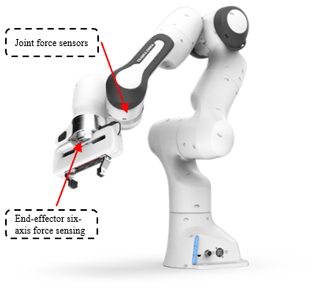
Commonly used robot manufacturers, including Universal Robots and Franka Emika, usually design robots with 6 or 7 degrees of freedom (DoFs) with better force interaction performance as well as positional accuracy (Song et al., 2022; Li et al., 2024). ABB design theirs as an industrial robot with poorer force interaction performance and absolute accuracy (Kamali and Bonev, 2019). The choice of the widely used 7-degree-of-freedom Franka Emika serial robot as the manipulator for collaborative assembly tasks is supported by its remarkable flexibility and precision, commonly utilized in gripping and pose control research (Li et al., 2024). The serial robot is primarily utilized to perform precise grasping and assembly of conductive elements, employing a hybrid force–position control strategy to achieve compliant assembly. The schematic diagram of the Franka Emika serial robot is presented in Fig. 2.
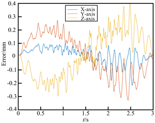
The serial robotic traversed from an initial position to a target point at (0.4, 0.3, 0.25) with a fixed orientation, employing motion interpolation during the movement. Throughout the entire traversal, positional error measurements were sampled at a 1000 Hz rate, enabling the verification of the system's positional accuracy in accordance with predefined precision standards.
As illustrated in Fig. 3, the experimental error analysis reveals that the maximum deviations in the X, Y, and Z directions throughout the experiment did not surpass 0.4 mm. Notably, when approaching intermediate positions, errors were confined within 0.1 mm, showcasing a commendable level of motion accuracy for a single serial robot. However, despite this high precision, the standalone robot's performance falls short of meeting the stringent requirements for precision assembly tasks.
3.2 Direct force–position control
The serial robot incorporates torque sensors in all seven of its joints. By processing the measurements from these joint torque sensors through a dynamic model, an estimated six-dimensional external force vector, denoted as Fs, is obtained at the end effector. The impedance controller's formulation is detailed as follows:
In Eq. (1), Fs represents a 6 × 1 external force vector, xs denotes the desired 6 × 1 reference pose vector processed by the impedance controller, xsd is the original desired 6 × 1 pose vector, Md represents the inertia parameter matrix, Dd is the damping parameter matrix, and Kd signifies the stiffness parameter matrix. Adjusting these three parameter matrices can modify the force characteristics at the end effector of the serial robot.
The dynamic model of a serial robot can be represented as follows:
In Eq. (2), q represents the joint position vector, Ms(q) denotes the inertia matrix, ) stands for the Coriolis and centrifugal force matrix, Gs(q) is the gravity matrix, τd represents the joint torques vector, τs is the external-torque acting vector on the joints, and Fd and Fs are the six-dimensional force control matrix and external force vector, respectively. represents the transpose of the Jacobian matrix, which facilitates the transformation of external forces acting on the end effector of a robotic arm into the joint space.
By combining Eqs. (1) and (2), the following impedance control calculation formula can be derived:
Equation (3) excludes the external force vector, Fs, thereby mitigating the influence stemming from estimation errors of external forces at the end effector of serial robots. The impedance controller for serial robots is subsequently designed based on Eq. (3), ensuring a robust and precise control scheme tailored for mechanical systems.
In the course of performing peg-in-hole assembly operations, a robotic arm computes force information at each joint to ascertain the force conditions at its end effector. Subsequently, leveraging impedance control principles, adjustments are made to the end effector's pose to realize a hybrid force–position-compliant control strategy. This approach ensures both precision and compliance in the manipulation process. Figure 4 presents an exemplary direct force–position control system, showcasing the integration of these techniques for advanced mechanical manipulation.
In Fig. 4, joint force data are processed via kinematic and dynamic models mapped to the end effector's Cartesian space and adjusted by a direct force–position control algorithm for real-time adaptability to external force variations. This enhances positioning precision during assembly over standalone impedance control by swiftly compensating for external disturbances.
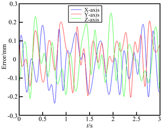
In the direct force–position control test, the serial robot's end effector moved 0.2 m down the z axis, feeding back positional data. Position errors are shown in Fig. 5.
In the final position, the errors in the X, Y, and Z directions were all less than 0.2 mm, indicating a high positioning accuracy. Therefore, direct force–position control was selected as the force control method for the assembly process in the serial–parallel robot collaborative assembly system. Sole reliance on a serial robot for assembly falls short of achieving the shaft-hole fitting accuracy specified in Sect. 2, thus necessitating the integration of a parallel robot for precise position and orientation adjustments to collaboratively complete the assembly task.
4.1 Analysis of workspace for the parallel robot
The analysis of the workspace of parallel robots facilitates effective motion planning, ensuring their efficient movement and task execution within the prescribed workspace. Given the high accuracy and efficiency of inverse kinematic computations for parallel robots, an approach combining inverse kinematic modeling with Monte Carlo algorithms is adopted to solve for the workspace of parallel robots, thereby enhancing the scientific rigor and practical applicability of the analysis.
Given the small overall dimensions of the assembly baseplate components, with the maximum distance between the two farthest assembly points not exceeding 100 mm, the range of degrees of freedom (DoFs) is specifically tailored during the workspace determination process for the 6-UPS (universal–prismatic–spherical) parallel robots as follows: the range of the X, Y, and Z translational DoFs is limited to −100 mm ≤ X ≤ 100 mm, −100 mm ≤ Y ≤ 100 mm, and 230 mm ≤ Z ≤ 300 mm, respectively. The rotational DoFs, denoted as ε, φ, and θ, are constrained to −5° ≤ ε ≤ 5°, −5° ≤ φ ≤ 5°, and −10° ≤ θ ≤ 10°, respectively. Taking into account the physical constraints of the branches, the range of the lengths of the branched links, Li (i = 1, 2,…, 6), and the rotational angles of the upper and lower hinges, α and β, respectively, are defined as follows: 0 mm ≤ Li ≤ 50.8 mm, α ≤ 30°, and β ≤ 20°.
Within these constraints, 200 000 points were randomly generated, and 136 534 of these points satisfied the conditions set for the parallel robot. These valid points were then plotted in MATLAB to form a point cloud, as shown in Fig. 6.
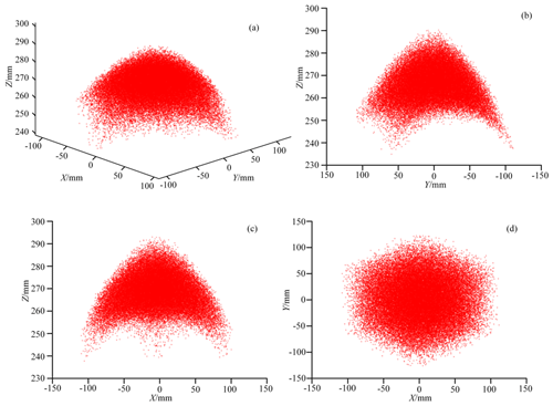
Figure 6Workspace of the parallel robot. (a) Three-dimensional representation of the parallel robot's workspace. (b) y–z-plane projection of the parallel robot's workspace. (c) x–z-plane projection of the parallel robot's workspace. (d) x–y-plane projection of the parallel robot's workspace. The red dots in each figure indicate the accessible positions of the center point of the robot's moving platform.
As shown in Fig. 6, the workspace of the parallel robot visually demonstrates a capability to meet the assembly space requirements spanning from −100 to 100 mm along the x and y axes and from 240 to 290 mm along the z axis.
4.2 Optimization of positioning accuracy of the parallel robot
The utilization of kinematic calibration techniques offers a means to refine the structural parameters of parallel robots, thereby enhancing their positioning accuracy without compromising their manufacturing or assembly precision (Yu, 2022). The comprehensive kinematic calibration process comprises four pivotal steps: pose measurement, error modeling, parameter identification, and error compensation.
4.2.1 Pose measurement
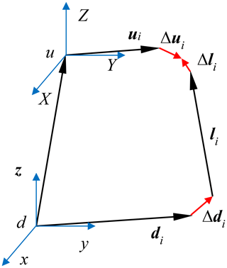
The parallel robot, featuring a 6-degree-of-freedom Stewart platform, is employed to conduct precise position and orientation adjustments, thereby assisting the serial robot in the shaft-hole assembly process. Under the assumption of zero backlash and machining errors in the hinges, with the centers of spherical joints, universal joints, and motor shafts being collinear and both the moving and the fixed platform being rigid, the positional errors in a parallel robot primarily stem from errors in the positions of the limb hinges and the lengths of the limbs. Given the difficulties in directly measuring these limb errors, a parameter identification approach is employed to solve for parametric errors by measuring the end-effector pose of the parallel robot. The closed-loop vector relationships depicting the errors in the six identical limbs are illustrated in Fig. 7.
The u () coordinate system is centered on the centroid of the moving platform, whereas the d () coordinate system is centered on the centroid of the fixed platform. Let li represent the length of the limbs, denote the position of the spherical joint center, and represent the position of the universal joint center, where i = 1, 2,…, 6. Furthermore, Δli, Δui, and Δdi represent the errors associated with li, ui, and di, respectively. The mathematical model for the limb li is formulated as follows:
where and P represent the rotation matrix and translation vector, respectively, that describe the transformation from the frame of reference associated with u to that of d. Through vector computations, the length of the limb can be expressed as a function f, which depends on the pose, , of the moving platform; the position of the spherical joint center, ui; and the position of the universal joint center, di. Taking the total differential of function f yields, Eq. (4) can be expressed in matrix form as follows:
where ΔQ represents the pose error of the moving platform, Jp represents the inverse Jacobian matrix of the parallel robot, and Ju denotes the transformation matrix for the positional error of the spherical joint centers. Jd denotes the transformation matrix for the positional error of the universal joint center.
Assuming that n measurements are conducted, n sets of pose errors can be obtained. Equation (5) comprises a total of 42 error parameters, necessitating the establishment of at least 42 equations or, equivalently, seven pose sets. To enhance the accuracy of identification results, it is generally advisable to select as many measurement poses as possible, i.e., n ≥ 7. The pose error matrix, Δg, can be represented as . The error model is formulated as JpΔQ=JcΔx, where (E is a 6 × 6 identity matrix) and .
By arranging the n pose sets into a matrix, the relationship between the end-effector pose errors and the structural parameter errors of the platform can be derived as follows:
where and .
4.2.2 Parameter identification
Parameter identification is a process that utilizes experimental measurement data to estimate the structural parameters of a parallel robot. The total least-squares (TLS) method, as a nonlinear identification approach, simultaneously accounts for both measurement errors in the identification model and errors in the identification matrix, thereby enabling a more robust handling of random errors and enhancing the stability of the identification results (Xin et al., 2024).
Let Jx be defined as and formulate the error model of the parallel robot utilizing the TLS approach as follows:
Subsequently, the augmented matrix derived from Eq. (7) undergoes singular value decomposition, yielding Ux and Vx. By partitioning the columns of Vx, we obtain Sx. The final solution of the TLS method is then derived as
where ax represents the upper-left block matrix resulting from the right multiplication of the Householder matrix, Qx, with Sx, with v1 being a row vector formed by the first row of Sx and Vx a matrix comprised of the subsequent rows of Sx.
To perform kinematic calibration on a parallel robot, it is first necessary to derive an error model based on the inverse kinematic solution. Subsequently, the parameters of this model are identified using the TLS method. After calculating the structural parameter errors, these errors are incorporated into the parallel robot and subjected to iterative refinement until the pose of the moving platform of the parallel robot satisfies the specified requirements.
4.3 Simulation and experiments
The detailed procedure for optimizing the precision of a parallel robot utilizing inverse kinematic calibration is as follows: initially, nominal values are assigned to the robot's structural parameters, including the spherical joint coordinates (), revolute joint coordinates (), and branch lengths (). The theoretical values of the branch lengths (li) are calculated based on the theoretical end-effector pose (xa) and input to the actuators to control the motion of the moving platform. Next, measurement devices such as motion capture systems are employed to acquire the measured end-effector pose (xs), and structural parameters are refined through error identification. The refined parameters are then substituted into the forward kinematic solution of the parallel robot to obtain corrected pose values. Finally, the corrected results are evaluated against preset accuracy requirements; if they meet the criteria, the corrected values are adopted as the actual structural parameters for control; if not, the process is reiterated with the updated pose errors until the requirements are satisfied.
After selecting the pose points, the error values identified for the parallel robot are optimized. The validity of the error model and the positioning accuracy optimization algorithm are verified by comparing the translational and rotational errors before and after optimization. The theoretical values of the structural parameters of the parallel robot, derived from the three-dimensional model, are shown in Table 2.
The parallel robot possesses favorable accessibility within an intermediate region slightly smaller than its operational workspace. Within this region, 20 pose points were randomly chosen for conducting precision optimization experiments. Table 3 presents the parameters of the selected pose points.
Considering workspace constraints and theoretical manufacturing/assembly errors, the position error range for the center of the parallel robot's moving platform, including rotation errors, is set at ±5 mm. The error range for the three rotational directions of the parallel robot's moving platform is selected as −0.5 to 0.5°. Figure 8 shows the maximum translational errors of −4.9863, 4.5961, and 4.6987 mm along the x, y, and z axis, respectively, and the maximum rotational deviations along the x, y, and z axis are found to be 0.4810, 0.4743, and 0.4969°, respectively, as randomly generated by MATLAB.
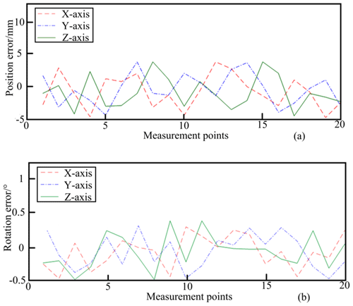
Figure 8Initial position and rotation error of the parallel robot: (a) position errors and (b) rotation errors.
The kinematic parameters of the parallel robot were identified using the TLS method, resulting in a final error range of −0.05 to 0.05 mm. The error identification encompassed parameters such as rod lengths and joint position errors. The identified error values are presented in Table 4.
Upon incorporating the precisely identified parametric errors into the theoretical inverse kinematic model of the parallel robot, we accurately calculated the branch lengths under the specified pose. These precise branch lengths were then input into the refined forward-kinematic model of the parallel robot to derive the exact position and orientation of the end effector. The results were an optimized end-effector position and rotational errors as a measure of improved accuracy. Subsequent to optimizing the positioning accuracy of the parallel robot, the maximum translational errors along the x, y, and z axis were significantly mitigated to 0.0089, 0.0098, and 0.0098 mm, respectively, and the maximum rotational errors along the x, y, and z axis to 0.0000191, 0.0000173, and 0.0000133°, respectively, as presented in Fig. 9.
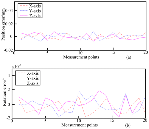
Figure 9Translation and rotation error diagram after positioning accuracy optimization: (a) position errors and (b) rotation errors.
Evidently, the positioning accuracy of the parallel robot has been significantly enhanced through kinematic calibration based on the TLS method. The enhanced positional accuracy now aligns with the assembly tolerance dimension of 0.016 mm. The integration with the compliant assembly capabilities of serial robots holds the potential to elevate assembly quality in theory. However, the reality of manufacturing errors and assembly deviations may introduce challenges. Therefore, it is imperative to conduct additional validation through precision optimization experiments and real assembly tests on a dedicated experimental platform.
5.1 Experimental study on the positioning accuracy of the parallel robot
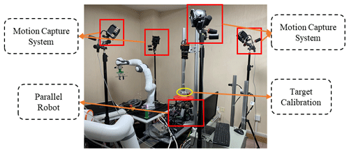
The positioning accuracy optimization test bed for parallel robots comprises a robot, calibration targets, and a motion capture system equipped with four cameras, as shown in Fig. 10.
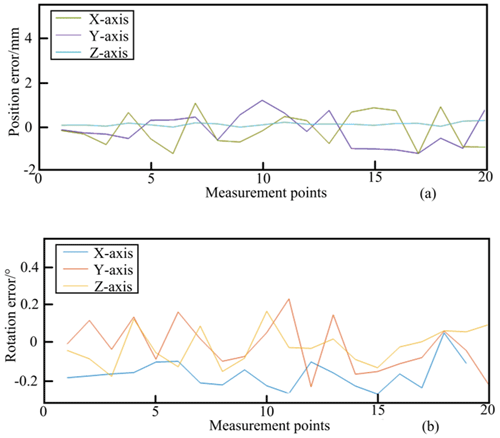
In total, 20 simulated pose points were measured, calibrated, and re-measured, yielding initial pose errors of 5.5945 mm, 4.8360 mm, 0.2990 mm, 0.3687°, 0.2334°, and 0.3623° for the parallel robot. Figure 11 shows the results.
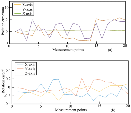
Figure 11Initial position and rotation errors of the parallel robot: (a) position errors and (b) rotation errors.
Through four iterations of the positioning accuracy optimization process for the parallel robot, utilizing the TLS method and incorporating 60 equations derived from 20 measured datasets, the identified overall parameter errors are presented in Table 5.
Calculated hinge errors should be below 0.5 mm based on manufacturing tolerances. Most errors in the table are within limits, with a few exceptions.
After three rounds of positioning accuracy optimization, the parallel robot's position was reassessed with 20 datasets, yielding maximum positional errors of 1.5590, 1.5676, and 0.2258 mm in the X, Y, and Z directions, respectively. These represent improvements of 4.0035, 3.2684, and 0.0732 mm over the initial positional errors in those directions.
Due to the significant angular measurement errors inherent in the motion capture system, the optimization method focused on positioning accuracy has exhibited less efficacy in enhancing attitude precision compared to its impact on positional accuracy. Specifically, the maximum deviations in rotational accuracy were recorded in the X, Y, and Z directions to be 0.2607, −0.2252, and 0.1974°, respectively. These values represent improvements of 0.1080, 0.0082, and 0.1649° over the initial rotational errors in those directions. Figure 12 depicts the pose errors after the optimization of positioning accuracy.
5.2 Experimental investigation on collaborative assembly
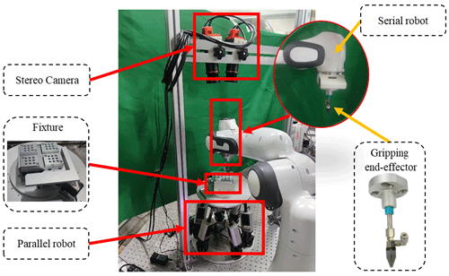
The experimental setup for cooperative assembly using dual robots principally consists of a fixture, a parallel robot, a serial robot, a gripping end effector, and two pairs of stereo cameras, as depicted in Fig. 13.
Figure 13 presents the experimental setup, featuring a high-precision machined fixture, a 6-DoF (6 degrees of freedom) Stewart parallel robot, a 7-DoF (7 degrees of freedom) Franka Emika robotic arm as the serial robot, a BML-20301 side conventional-type compliant tactile gripper serving as the gripping end effector, and two stereo camera systems, each consisting of Hikvision MV-CS032-10GC units.
Within the system, the fixture is mounted on the motion platform of the parallel robot and tasked with securely fixing the assembly baseplate components. The parallel robot is responsible for adjusting the assembly pose of the baseplate to facilitate precise alignment. The serial robot, integrated with the gripping end effector, collaborates to grasp the conductive parts and execute axle-hole assembly. The stereo cameras perform critical functions in recognizing and localizing the conductive parts, monitoring their poses, the poses of the assembly baseplate components, and the status of point-to-point assembly. The detailed process flow for achieving high-density precise axle-hole assembly with this system is as follows:
- 1.
The cameras identify and localize the conductive parts through advanced image processing techniques.
- 2.
Subsequently, the cameras detect and pinpoint the locations of unoccupied holes on the assembly baseplate.
- 3.
The serial robot precisely grasps the conductive part and maneuvers it to hover above the designated unoccupied hole.
- 4.
The vision system conducts a thorough pose inspection of the conductive part to ensure accurate alignment.
- 5.
Based on the pose of the conductive part, the parallel robot subtly adjusts the pose of the assembly baseplate component for precise mating.
- 6.
Lastly, the serial robot, employing compliant control strategies, accomplishes the delicate axle-hole assembly, ensuring high precision and repeatability.
After successfully executing 36 rounds of dual-robot collaborative assembly processes, the feasibility and robustness of the assembly system under investigation is conclusively proven.
This study introduces a novel high-precision compliant assembly approach, grounded on direct force–position control for the serial robot and optimization of positioning accuracy for the parallel robot. The proposed methodology significantly enhances the efficiency of high-density axial-hole assembly in electronic equipment components. The primary contributions of this method encompass (1) the adoption of direct force–position control for the serial robot, achieving compliant assembly while maintaining high positioning accuracy, and (2) the utilization of an error identification method based on the total least-squares algorithm to discern structural parameter errors in the parallel robot.
This approach is distinguished by its high precision in physical assembly. The positioning accuracies are as follows: for serial robots, the positional errors are universally below 0.2 mm, with select positions exhibiting errors of less than 0.1 mm. In contrast, for parallel robots, the maximum translational errors in the X, Y, and Z directions are 1.5590, 1.5676, and 0.2258 mm, respectively, representing improvements of 4.0035, 3.2684, and 0.0732 mm over pre-optimization levels. The maximum rotational errors around the x, y, and z axes are 0.2607, −0.2252, and 0.1974°, respectively, signifying enhancements of 0.1080, 0.0082, and 0.1649° compared to the pre-optimized state.
Ownership issues are involved, and therefore data cannot be disclosed.
LD: investigation, conceptualization, and writing (review and editing); JM: data curation, formal analysis, and writing (original draft); JC: software, validation, and visualization; and DW: funding acquisition, project administration, and supervision.
The contact author has declared that none of the authors has any competing interests.
Publisher's note: Copernicus Publications remains neutral with regard to jurisdictional claims made in the text, published maps, institutional affiliations, or any other geographical representation in this paper. While Copernicus Publications makes every effort to include appropriate place names, the final responsibility lies with the authors.
We sincerely thank Zhengyu Wang from the School of Mechanical Engineering at Hefei University of Technology for his unwavering support of this research. His valuable insights and scientific methods have made significant contributions to the development of this research. His support and professional knowledge played an important role in the successful completion of this work, for which we sincerely thank him. In addition, the authors would like to thank the Key Science and Technology Special Project of Anhui Province and the Fundamental Research Funds for the Central Universities, which provided a favorable research environment for this study.
This research has been supported by the Key Science and Technology Special Project of Anhui Province (grant no. 202203a05020007) and the Fundamental Research Funds for the Central Universities (grant no. JZ2024HGTG0299).
This paper was edited by Zi Bin and reviewed by three anonymous referees.
An, H., Ye, C., Yin, Z. K., and Lin, W. Y.: Neural Adaptive impedance control for force tracking in uncertain environment, Electronics, 12, 640, https://doi.org/10.3390/electronics12030640, 2023.
Chen, C., Sun, H. H., Ni, D. H., and Gao, X. L.: Research on welding technology of surface mount device on high integration substrate, ICMMT, 1-3, https://doi.org/10.1109/ICMMT52847.2021.9618061, 2021.
Choi, S., Kim, D., Kim, Y., Kang, Y., Yoon, J., and Yun, D.: A novel compliance compensator capable of measuring six-axis force/torque and displacement for a robotic assembly, IEEE-ASME T. Mech., 29, 29–40, https://doi.org/10.1109/TMECH.2023.3294510, 2023.
Chu, H. P., Qi, B., Qiu, X. S., and Zhou, Y. L.: 6-DOF wheeled parallel robot and its automatic type synthesis method, Mech. Mach. Theory, 169, 104646, https://doi.org/10.1016/j.mechmachtheory.2021.104646, 2022.
Gai, Y. H., Guo, J. M., Wu, D., and Chen, K.: Feature-based compliance control for precise peg-in-hole assembly, IEEE T. Ind. Electron., 69, 9309–9319, https://doi.org/10.1109/TIE.2021.3112990, 2021.
Jamwal, P. K., Kapsalyamov, A., Hussain, S., and Ghayesh, M. H.: Performance based design optimization of an intrinsically compliant 6-dof parallel robot, Mech. Based Des. Struc., 50, 1237–1252, https://doi.org/10.1080/15397734.2020.1746669, 2020.
Jiang, J. G., Huang, Z. Y., Bi, Z. M., Ma, X. F., and Yu, G.: State-of-the-Art control strategies for robotic PiH assembly, Robot. Cim.-Int. Manuf., 65, 101894, https://doi.org/10.1016/j.rcim.2019.101894, 2020.
Jiang, T., Cui, H. H., Cheng, X. S., and Tian, W.: A measurement method for robot peg-in-hole prealignment based on combined two-level visual sensors, IEEE T. Instrum. Meas., 70, 5000912, https://doi.org/10.1109/TIM.2020.3026802, 2020.
Kamali, K. and Bonev, I. A.: Optimal experiment design for elasto-geometrical calibration of industrial robots, IEEE-ASME T. Mech., 24, 2733–2744, https://doi.org/10.1109/TMECH.2019.2944428, 2019.
Kumar, S., Wöhrle, H., Fernández, J. D. G., Müller, A., and Kirchner, F.: A survey on modularity and distributivity in series-parallel hybrid robots, Mechatronics, 68, 102367, https://doi.org/10.1016/j.mechatronics.2020.102367, 2020.
Lee, H., Park, S., Jang, K., Kim, S., and Park, J.: Contact state estimation for peg-in-hole assembly using gaussian mixture model, IEEE Robotics and Automation Letters, 7, 3349–3356, https://doi.org/10.1109/LRA.2022.3146949, 2022.
Li, D. X., Zhao, H., Ge, D. S., Li, X. F., and Ding, H.: A novel robotic multiple peg-in-hole assembly pipeline: modeling, strategy, and control, IEEE-ASME T. Mech., 29, 2602–2613, https://doi.org/10.1109/TMECH.2023.3337102, 2023.
Li, W. B., Wu, H. M., and Jin, L.: A Lower Dimension Zeroing Neural Network for Time-Variant Quadratic Programming Applied to Robot Pose Control, IEEE T. Ind. Inform., 20, 1–9, https://doi.org/10.1109/TII.2024.3413317, 2024.
Lilge, S., Nuelle, K., Childs, J. A., Wen, K., Rucker, D. C., and Burgner-Kahrs, J.: Parallel-continuum robots: a survey, IEEE T. Robot., 40, 3252–3270, https://doi.org/10.1109/TRO.2024.3415230, 2024.
Niu, J. Y., Wang, H. B., Jiang, Z. W., Chen, L., Zhang, J. J., Feng, Y. F., and Guo, S. J.: Kinematic Analysis of a serial-parallel hybrid mechanism and its application to a wheel-legged robot, IEEE Access, 8, 111931–111944, https://doi.org/10.1109/ACCESS.2020.3001653, 2020.
Russo, M., Zhang, D., Liu, X. J., and Xie, Z. H.: A review of parallel kinematic machine tools: Design, modeling, and applications, Int. J. Mach. Tool. Manu., 196, 104118, https://doi.org/10.1016/j.ijmachtools.2024.104118, 2024.
Song, D., Xiao, X., Ma, J., and Zhang, L.: Modeling and control system experiment of a novel series three-axis stable platform, Mech. Sci., 15, 209–221, https://doi.org/10.5194/ms-15-209-2024, 2024.
Song, Y., Liu, M., Lian, B. B., Qi, Y., Wang, Y., Wu, J., and Li, Q.: Industrial serial robot calibration considering geometric and deformation errors, Robot. Cim.-Int. Manuf., 76, 102328, https://doi.org/10.1016/j.rcim.2022.102328, 2022.
Su, J. H., Liu, C. K., and Li, R.: Robot precision assembly combining with passive and active compliant motions, IEEE T. Ind. Electron., 69, 8157–8167, https://doi.org/10.1109/TIE.2021.3108710, 2021.
Sun, H. H., Zhang, Y. J., Xie, B., and Zi, B.: Dynamic modeling and error analysis of a cable-linkage serial-parallel palletizing robot, IEEE Access, 9, 2188–2200, https://doi.org/10.1109/ACCESS.2020.3047650, 2020.
Sun, T., Lian, B. B., Yang, S. F., and Song, Y. M.: Kinematic calibration of serial and parallel robots based on finite and instantaneous screw theory, IEEE T. Robot., 36, 816–834, https://doi.org/10.1109/TRO.2020.2969028, 2020.
Sun, T. R., Peng, L., Cheng, L., Hou, Z.-G., and Pan, Y. P.: Composite learning enhanced robot impedance control, IEEE T. Neur. Net. Lear., 31, 1052–1059, https://doi.org/10.1109/TNNLS.2019.2912212, 2019.
Ti, B. Y., Gao, Y. S., Shi, M., and Zhao, J.: Generalization of orientation trajectories and force–torque profiles for learning human assembly skill, Robot. Cim.-Int. Manuf., 76, 102325, https://doi.org/10.1016/j.rcim.2022.102325, 2022.
Tian, W., Ding, Y. F., Du, X. D., Li, K., Wang, Z. H, Wang, C. R., Deng, C., and Liao, W. H.: A review of intelligent assembly technology of small electronic equipment, Micromachines, 14, 1126, https://doi.org/10.3390/mi14061126, 2023.
Unten, H., Sakaino, S., and Tsuji, T.: Peg-in-hole using transient information of force response, IEEE-ASME T. Mech., 28, 1674–1682, https://doi.org/10.1109/TMECH.2022.3224907, 2023.
Wang, L., Fang, Y. F., and Zhang, D.: Design of 4-DOF hybrid parallel robots with an integrated three-fingered robot end effector, Mech. Mach. Theory, 189, 105443, https://doi.org/10.1016/j.mechmachtheory.2023.105443, 2023.
Xin, D. K., Zhu, J. C., He, C. S., and Hua, H. X.: Low frequency load identification under high noise level using weighted total least squares, Measurement, 115125, https://doi.org/10.1016/j.measurement.2024.115125, 2024.
Yin, Z. P., Huang, Y. A., Yang, H., Chen, J. K., Duan, Y. Q., and Chen, W.: Flexible electronics manufacturing technology and equipment, Sci. China Technol. Sc., 65, 1940–1956, https://doi.org/10.1007/s11431-022-2098-1, 2022.
Yu, D. Y.: Kinematic calibration of parallel robots based on l-infinity parameter estimation, Machines, 10, 436, https://doi.org/10.3390/machines10060436, 2022.
Zhang, Q., Hu, Z. T., Wan, W. W., and Harada, K.: Compliant peg-in-hole assembly using a very soft wrist, IEEE Robotics and Automation Letters, 9, 17–24, https://doi.org/10.1109/LRA.2023.3331623, 2023.
Zhang, T., Liang, X. H., and Zou, Y. B.: Robot peg-in-hole assembly based on contact force estimation compensated by convolutional neural network, Control Eng. Pract., 120, 105012, https://doi.org/10.1016/j.conengprac.2021.105012, 2022.
Zhao, H., Chen, Y. X., Li, X. F., and Ding, H.: Robotic peg-in-hole assembly based on reversible dynamic movement primitives and trajectory optimization, Mechatronics, 95, 103054, https://doi.org/10.1016/j.mechatronics.2023.103054, 2023.
Zhao, Y. N., Gao, F., Zhao, Y., and Chen, Z. J.: Peg-in-hole assembly based on six-legged robots with visual detecting and force sensing, Sensors, 20, 2861, https://doi.org/10.3390/s20102861, 2020.
Zhu, X., Liu, Z. H., Cai, C. G., Yang, M., Zhang, H., Fu, L., and Zhang, J.: Deep learning-based predicting and compensating method for the pose deviations of parallel robots, Comput. Ind. Eng., 191, 110179, https://doi.org/10.1016/j.cie.2024.110179, 2024.
- Abstract
- Introduction
- Analysis of assembly component features
- Force control of the serial robot
- Optimization of positioning accuracy for the parallel robot
- Experimental result
- Conclusion
- Data availability
- Author contributions
- Competing interests
- Disclaimer
- Acknowledgements
- Financial support
- Review statement
- References


