the Creative Commons Attribution 4.0 License.
the Creative Commons Attribution 4.0 License.
 | 06 Feb 2024
Dynamic analysis of a box-structured satellite deployment mechanism with self-actuated torsion joints
Renzhe Ma
Chun Su
This paper designed a kind of satellite deployment mechanism with a boxed structure and passive torsion joints. This deployment mechanism has significant strengths, including a high base frequency and stiffness, a high ratio of deployed and folded space occupation ratios, and self-actuated joints without needing any external power to drive. In order to analyze the dynamic characteristics of this mechanism, a simplified governing equation is proposed and dynamic behavior is studied systematically, including impact response, harmonic response, and modal analysis. Through systematic research, several conclusions are drawn. Firstly, when the deployment mechanism reached the ending stage of unfolding driven by passive torsional joints, the load base installed on top of the deployment mechanism generated a first-order sharp reaction force and multiple low-order shocks followed, and the system entered a stable state after a certain time of vibration. Secondly, the system can generate a high vibration magnitude at low-frequency excitation when the mechanism is in a fully deployed state and at high-frequency excitation when the mechanism is in a folded state. Thirdly, the first sixth-order natural frequency and vibration shape with different wall thicknesses are obtained by modal analysis. The result shows that only with a 2.5 mm wall thickness can the connecting rod satisfy the design requirement. Through dynamic behavior research, the structure characteristics are obtained which can be used for structure optimization and to provide an effective solution for the design of a box-structured satellite-unfolding mechanism with self-actuated torsion joints.
- Article
(5959 KB) - Full-text XML
- BibTeX
- EndNote


A space-folding mechanism is a new type of foldable and deployable space equipment, which adapts to the development of spacecraft in the direction of a large scale (Meguro et al., 2006; Angeletfi et al., 2019). The research and development of space-folding mechanisms can solve the space constraints in spacecraft navigation and carry as many tools and equipment as possible with the limited space and weight. At the same time, this can realize the compact layout of spacecraft components, improve the load capacity and use of space, and reduce production and transportation costs significantly.
NASA began studying the application of space-folding mechanisms as early as the 1960s. In the space exploration project of the United States, the space-folding mechanism is widely used in the development and construction of satellites, space stations, and probes (Ma et al., 2018; Liu et al., 2018; Hu et al., 2022). With the requirement of satellite miniaturization, Choi proposed a high-precision extension arm design scheme (Arita et al., 2018; Choi et al., 2019), which is mainly used for space optical telescopes. The extension arm was based on a quadrangular column and was equipped with an upper panel and a lower panel, a connecting rod, and a supporting module. In order to further improve the folding and unfolding accuracy of the mechanism, a special assembly mold was developed, and based on the precision detection platform built by five contactless laser displacement sensors, the unfolding accuracy of the mechanism was experimentally studied and the micro-unfolding accuracy was achieved. In the 1990s, ATK Company developed a kind of UltraFlex solar wing (Spence et al., 2006; Eacre and White, 2010), which mainly consists of a flexible triangle film, a center hub, a compression band, and an expansion mechanism. The expansion principle is similar to that of a folding fan, the torsion spring located at the center is used to expand, and the shape is circular after expansion.
The European Union and the European Space Agency have also conducted a lot of research on space-folding mechanisms, mainly applied to the expansion and contraction of solar panels as well as the construction of satellites and space vehicles. The European Space Agency and a number of research institutions such as Georgia Technical University (Datashvili, 2013; Medzmarlashvili et al., 2013) jointly developed a conical-ring deployable antenna with a diameter of up to 6 m after development. The antenna is composed of a number of trapezoidal components, including upper and lower V-shaped folding rods, vertical rods, synchronous hinges, driving springs, and cable components. An extended arm of a triangular prism with the triangular prism as the unfolding unit was proposed (Sahn et al., 2018), which was composed of a rigid triangular frame, an upper and lower folding arm, a diagonal cable, and other structures. The device is located in the middle of the upper and lower folding arm and uses the transmission mode combined with the motor and the screw to tighten the diagonal cable when deployed, thereby increasing the rigidity of the device.
A triangular prism extension arm with a super-elastic hinge was proposed (Yang et al., 2016, 2018). The extension arm was also a modular unit with a triangular prism, and its main components include a longitudinal rod, a rope, a triangular frame, casing, and a super-elastic hinge. An expandable triangular prism type extension arm composed of a longitudinal rod, a beam, a tension cable, and a hinge was proposed (Gao et al., 2020). The extension arm is driven by a spring taking into account the load. The whole is made of lightweight materials, the longitudinal rod is made of carbon fiber, and the other parts are made of aluminum alloy. After the extension arm is unfurled and fixed, the longitudinal rod supports the extension arm, and at the same time, the tension cable is tightened to increase the strength of the extension arm. China's Shijian-20 satellite is equipped with the solar wing with the largest area and longest wingspan at present, which is composed of six solar panels, i.e., four transverse solar panels and two longitudinal solar panels (Cui and Tang, 2020). Based on the traditional folding fan principle, a deep study of the fan solar wing was made (Jian and Ce, 2020), and the synchronous mechanism, self-locking hinge, and driving mechanism were designed and used the multi-body dynamics software to simulate and analyze the kinematics and dynamics of the mechanism. Based on the scissor's mechanism, the configuration method of the rib-element folding mechanism was proposed (He et al., 2021), and the rib-element folding mechanism and expansion method of the multi-modular folding mechanism were proposed based on the envelope cone method, which verified that the method was designed. A series of analyses and experiments was conducted in the face of the demand to replace the ultra-thin aluminum honeycomb materials used in manufacturing solar panels (Guan et al., 2023). A surface defect detection method for flexible solar wing piano hinges was proposed based on deep learning (Wang et al., 2023). In this method, cameras are used to record the hinges, and a big-data analysis method is utilized to analyze the recorded data, which not only reduces the performance requirements of computers, but also improves the detection accuracy and efficiency.
In this paper, a box-structured satellite-unfolding mechanism based on a precision positioning self-actuated torsion joint is designed, and the dynamic simulation of the folding mechanism is carried out in three aspects based on multi-body dynamics, including shock response, modal analysis, and vibration analysis. Through multi-angle dynamic analysis, the structural dynamic response is obtained, and based on the response, the structure is optimized, which provides a reliable solution for the analysis and optimal design of this kind of structure.
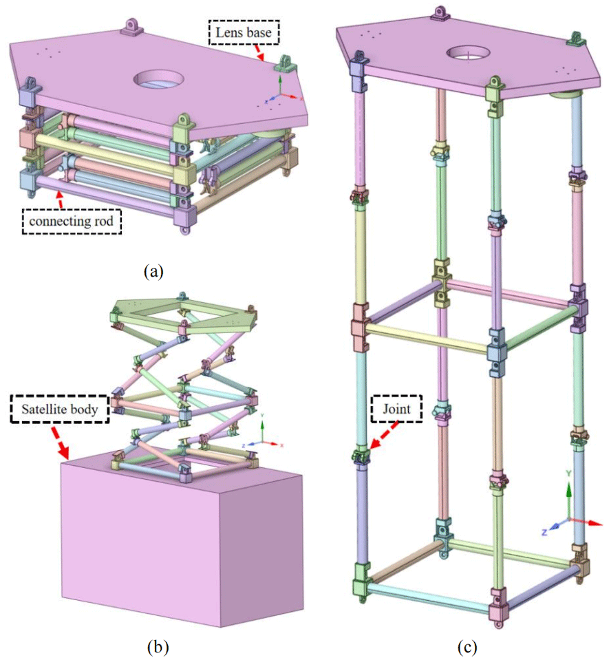
Figure 1Unfolding process of the deployable mechanism. (a) Fully folded; (b) half-deployed; (c) fully deployed.
2.1 Physical model
Figure 1 shows the unfolding process of the mechanism, Fig. 1a shows the fully folded state, Fig. 1b shows the half-deployed state, and Fig. 3c shows the fully deployed state. In addition, it can be seen that the unfolding mechanism mainly includes a load base, a connecting rod, and a torsion joint, and the four joints located on the bottom of the unfolding mechanism are installed on the satellite body. The load base is used to install the deep space exploration lens and to drive with the connecting rods and self-actuated joints. In addition, it should be noted that the connecting rod is made of carbon fiber considering its characteristics of high strength and low weight.
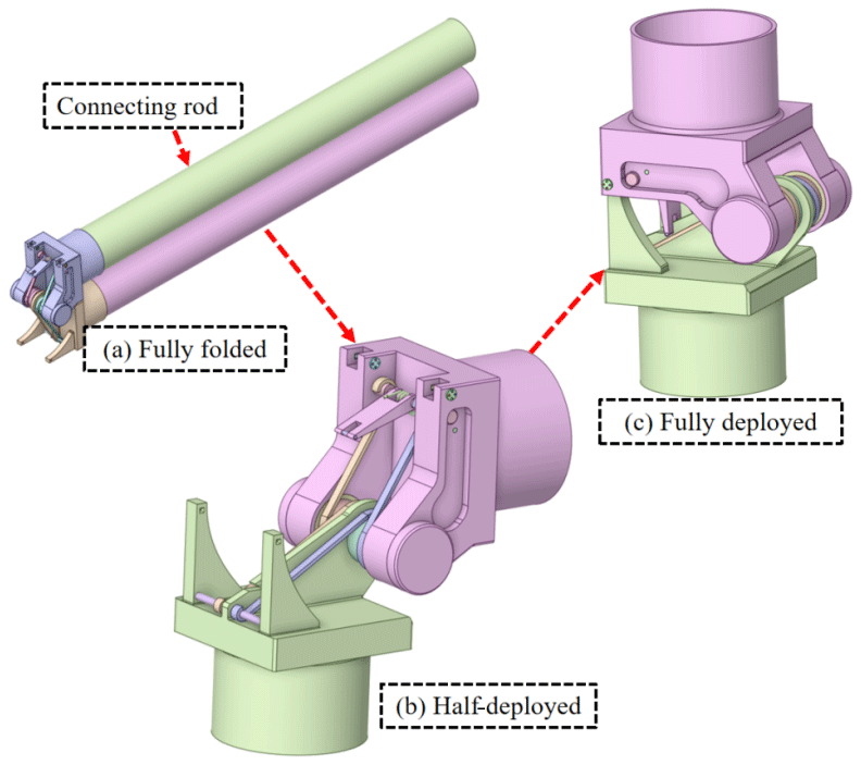
Figure 2 shows the detailed unfolding process and structure of the self-actuated joint, which has an energy storage unit to unfold the mechanism. As seen in Fig. 2a, each joint is bonded with two connecting rods in parallel. Under the driver of the joint, which has a custom-designed torque spring inside, the angle between the rods is increased from 0 to 180∘ gradually. After strict testing, the driven torque of the joint behaved near-linearly and from 0.9 to 0.3 Nm when the rod angle increased from 0 to 180∘.
2.2 Dynamic equation
In order to analyze the dynamic behavior and characteristics, the dynamic equation is proposed. For the spatial multi-degree-of-freedom mechanism, the Lagrange equation is used to establish the dynamic equation as follows:
where T is kinetic energy, qj is generalized coordinates, is generalized velocity, and Qj is generalized force.
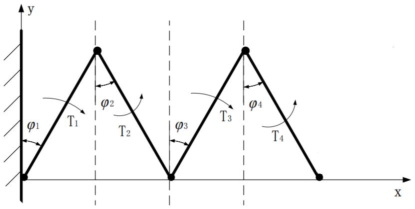
The box-structured space-folding mechanism consists of the same four modules as seen in Fig. 1, and a single-side module is adopted for analysis. The mechanism is simplified into four rigid rods connected in sequence from end to end. In order to facilitate the construction of the dynamic equation, the intermediate layer and the load plate are simplified as mass points, and the simplified model is shown in Fig. 3.
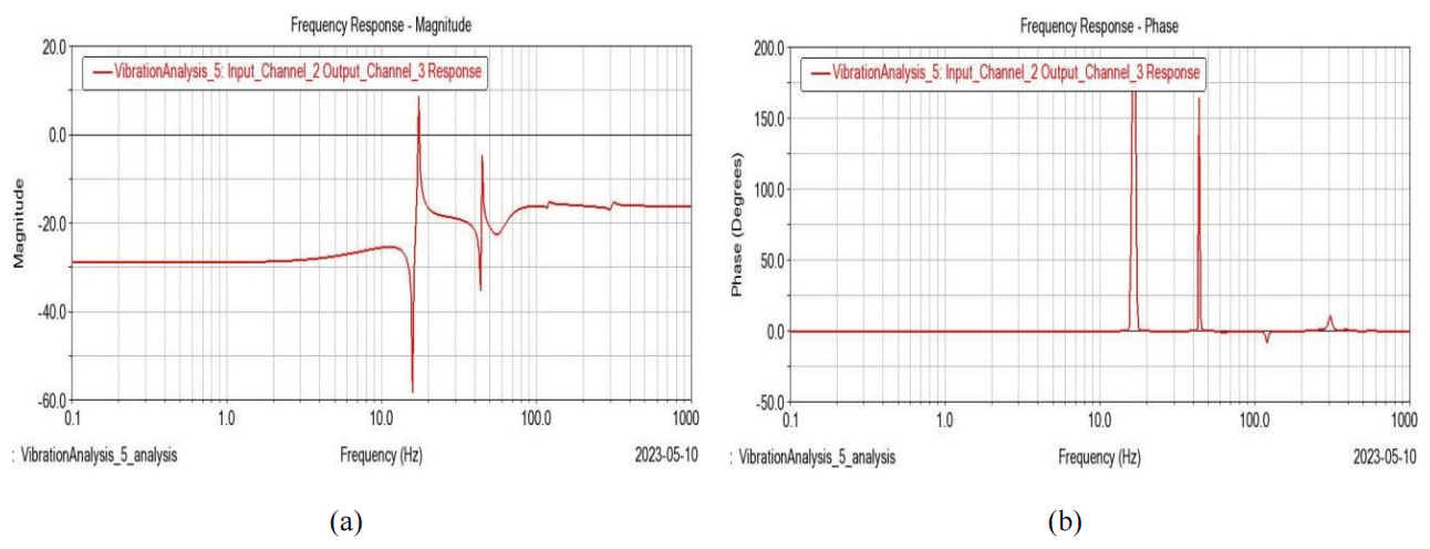
Figure 6Frequency response diagram (1 mm wall thickness connecting rod). (a) Frequency vs. magnitude diagram. (b) Frequency vs. phase diagram.
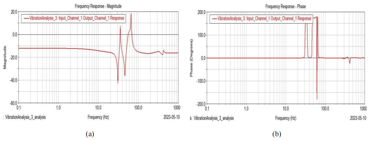
Figure 7Frequency response diagram (2 mm wall thickness connecting rod). (a) Frequency vs. magnitude diagram. (b) Frequency vs. phase diagram.
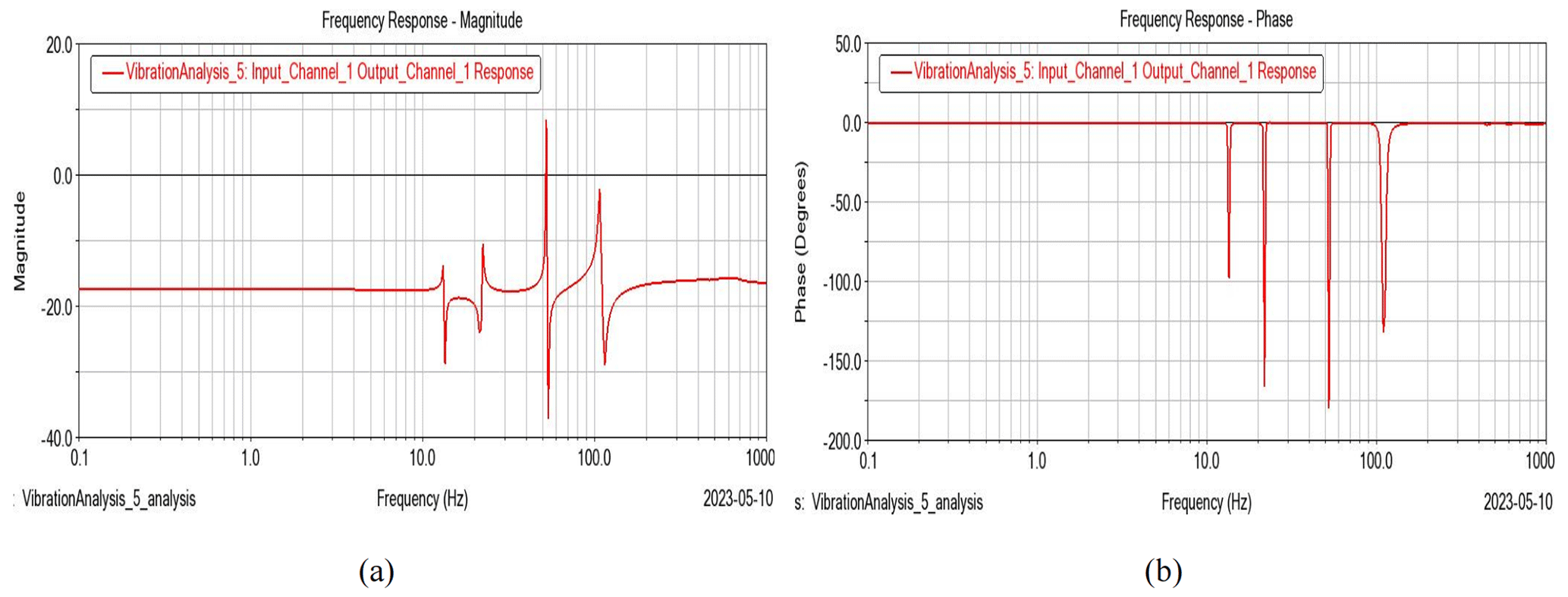
Figure 8Frequency response diagram (3.5 mm wall thickness connecting rod). (a) Frequency vs. magnitude diagram. (b) Frequency vs. phase diagram.
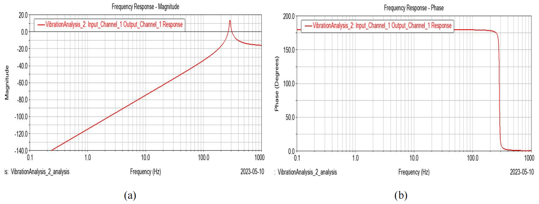
Figure 9Frequency response diagram (1 mm wall thickness connecting rod). (a) Frequency vs. magnitude diagram. (c) Frequency vs. phase diagram.
φi represents the angle between the ith rod and the y axis. Ti represents the torque acted on the ith rod, as shown in Fig. 3. Similarly, it can be seen that q1=φ1, q2=φ2, q3=φ3, and q4=φ4.
During the process of deployment, the four rods are all in plane motion, and the motion state of each rod at any time can be represented by four generalized coordinates, so the position of the centroid of the first rod at any time can be described as
where rix is the horizontal coordinate of the ith rod, riy is the vertical coordinate of the ith rod, and l is the length of the rod: ; .
Using vector ri as the displacement of the center of the ith rod,
where vi represents the velocity of the center of the ith rod; and ui1, ui2, ui3, and ui4 represent the line velocity of the ith rod under the generalized coordinates of q1, q2, q3, and q4.
Using φi as the angle displacement of the ith rod,
The linear velocity of each bar can be calculated by the motion equation of the centroid of each rod. In order to facilitate the calculation, we can decompose it into scalars in the x direction and y direction. The linear velocity of the centroid of the ith rod relative to the jth generalized coordinate in the x- and y-axis directions can be described as follows.
The angular velocity uij of the ith rod with respect to the jth generalized coordinate is
The kinetic energy Tni of the ith rod during the unfolding process can be written as
where vi is the line angle of the mass center of the rod, and js is the moment of inertia.
The total kinetic energy Tn of the unfolding system can be written as
where jij is the coefficient of the inertia and is written as
By substituting Tn into Eq. (1), the system of governing equations can be obtained as follows.
Without considering gravity and friction, there are only four driving torques and systems, and the generalized force can be expressed as
By substituting Eqs. (9) and (11) into Eq. (10), the governing equation can be simplified further and written as follows.
, , , and .
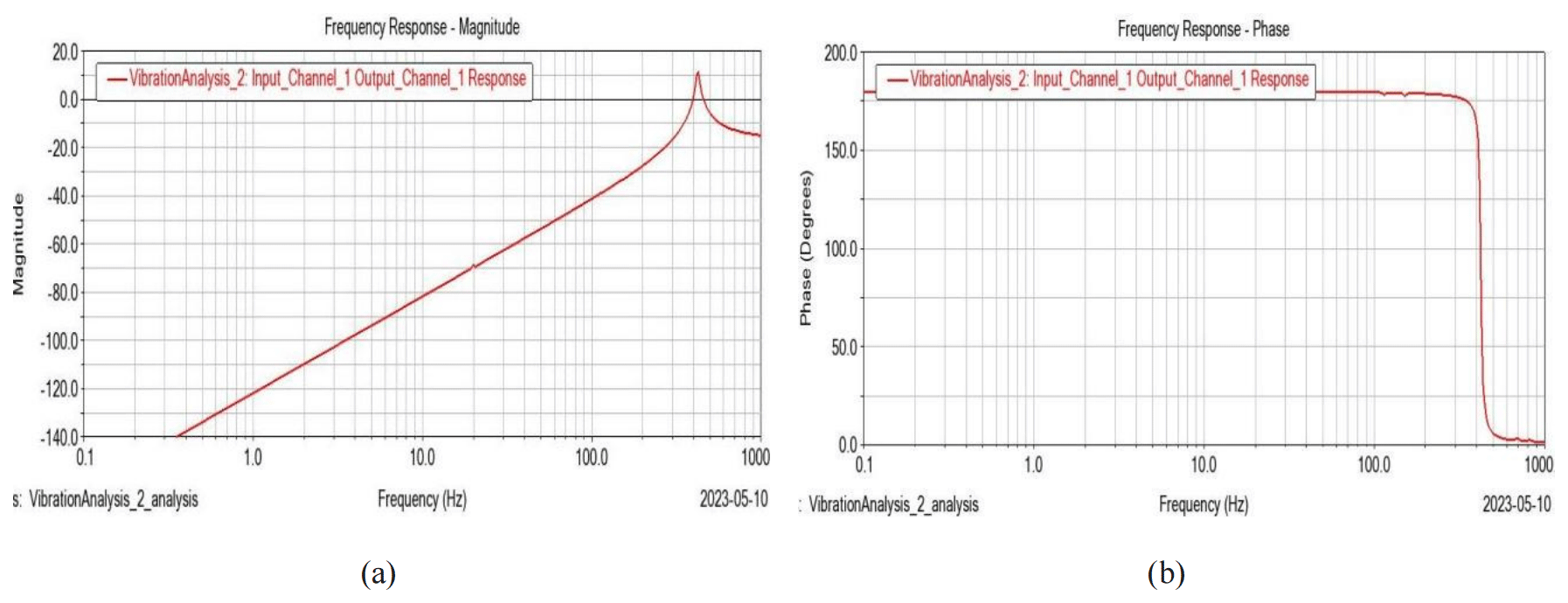
Figure 10Frequency response diagram (2 mm wall thickness connecting rod). (a) Frequency vs. magnitude diagram. (b) Frequency vs. phase diagram.
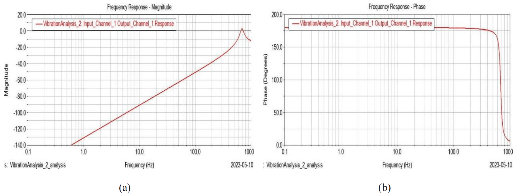
Figure 11Frequency response diagram (3.5 mm wall thickness connecting rod). (a) Frequency vs. magnitude diagram. (b) Frequency vs. phase diagram.
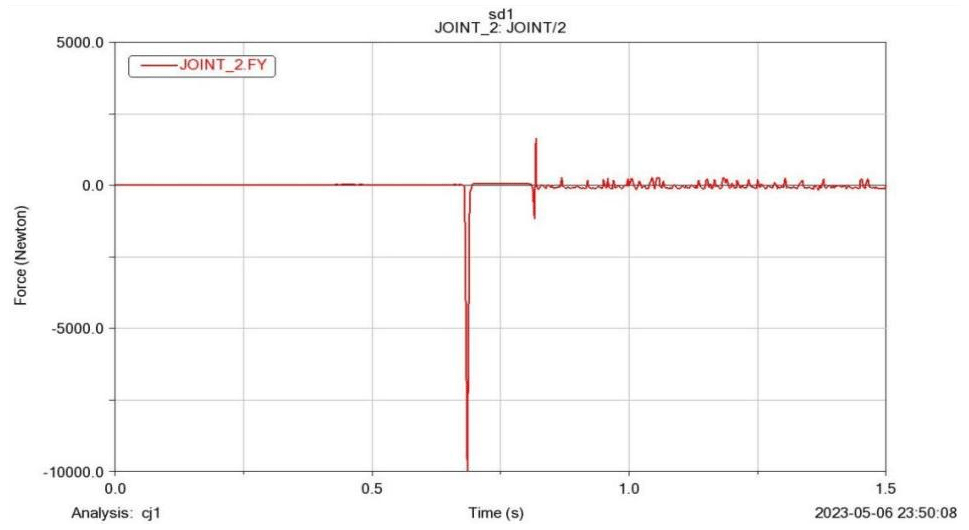
3.1 Impact dynamic analysis
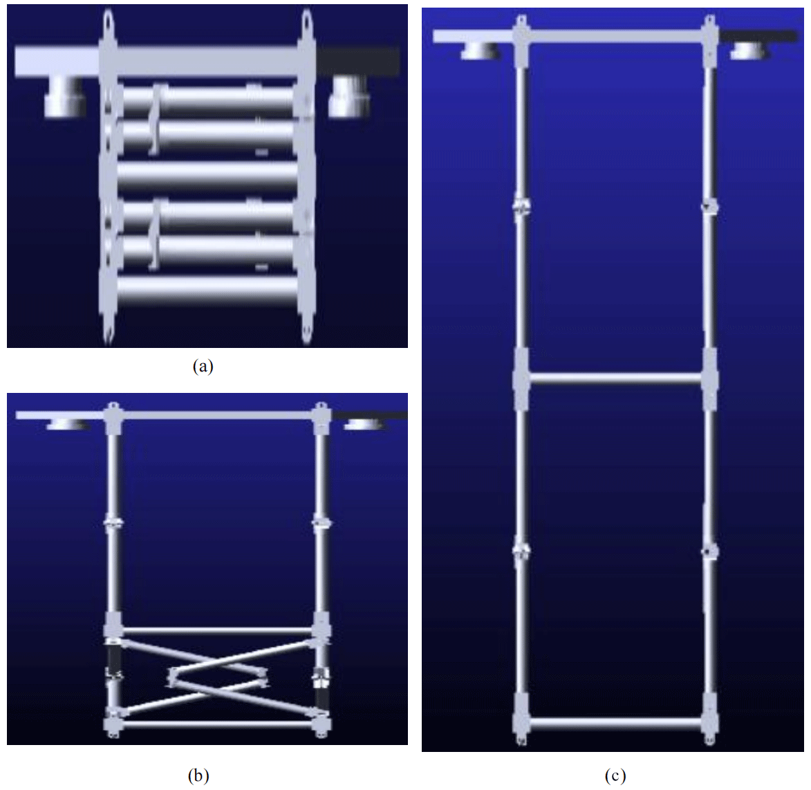
Considering that the deployment mechanism is driven by a self-actuated torsion joint, the initial driven torsion is 0.9 Nm and the final driven torsion is 0.3 Nm, respectively. When the deployment mechanism starts to deploy, the velocity of the load base increases gradually. The mechanism will lock in an instant while fully deployed, and the kinetic energy absorbed by the mechanism will have an impact on the satellite body, which may damage the satellite body. So, it is necessary to analyze the influence and find the solution if an unacceptable result is generated. Figure 4 shows the process from a folded state to a fully deployed state.
Figure 5 shows the time vs. impact force diagram, and it can be seen that, after 0.65 s stable deployment with zero impact force, the load base reached the limiting position, and a sharp peak reaction force was generated and almost reached 9800 N. After that, the load base started negative displacement, and the reaction force returned to zero and generated a small peak force again about 0.15 s later. The system reached a stable state.
The critical point of this impact analysis is to check whether the mechanism can bear the first-order impact reaction force. The damper would be added when the first-order impact force could generate damages.
3.2 Harmonic response analysis
The satellite works in space, and unpredictable excitation happens normally. However, the excitation frequency is random, and thus harmonic response analysis in a wide frequency range is a necessary option. In this section, the responses of the load base and connecting rod at wide-range harmonic excitation are shown.
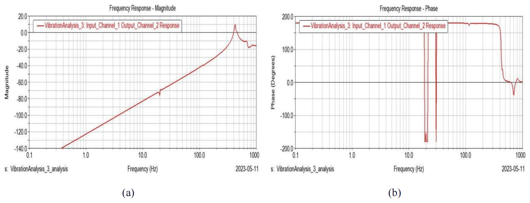
Figure 12Frequency response of the first layer of the connecting rod. (a) Frequency vs. magnitude diagram. (b) Frequency vs. phase diagram.
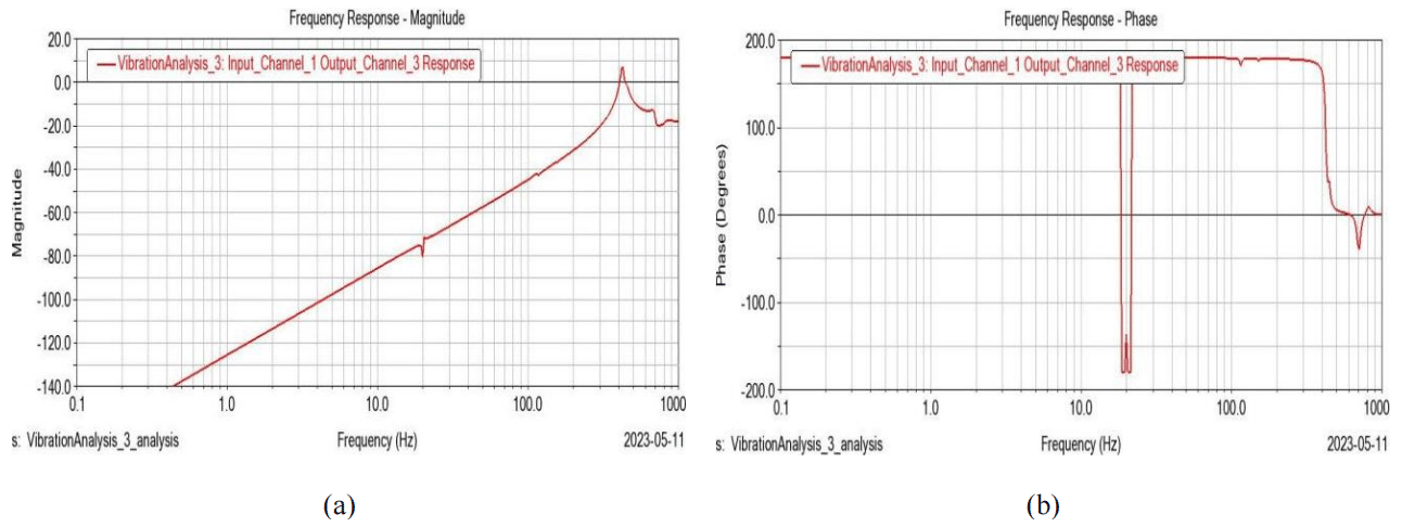
Figure 13Frequency response of the second layer of the connecting rod. (a) Frequency vs. magnitude diagram. (b) Frequency vs. phase diagram.
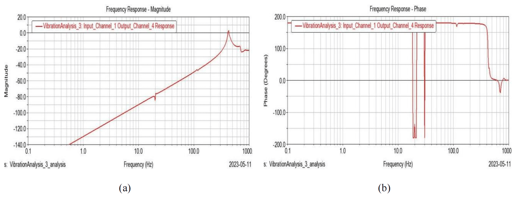
Figure 14Frequency response of the third layer of the connecting rod. (a) Frequency vs. magnitude diagram. (b) Frequency vs. phase diagram.
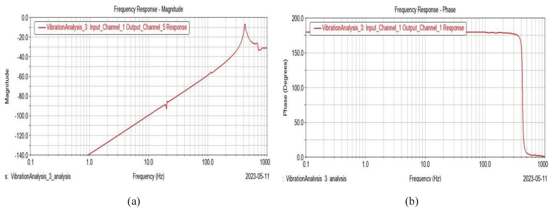
Figure 15Frequency response of the fourth layer of the connecting rod. (a) Frequency vs. magnitude diagram. (b) Frequency vs. phase diagram.
3.2.1 Harmonic response of the load base under the folded condition
To get the optimal design parameter of the connecting rod, the thickness of the rod is chosen as a variable. Figure 6 shows the frequency response diagram at the center of the load base, with 1 mm wall thickness connecting the rod under the folded condition.
Figure 6a shows the frequency vs. magnitude diagram, and Fig. 6b shows the frequency vs. phase diagram. It can be seen that, in Fig. 6a, the system suffers two significant increases in vibration amplitude at frequencies of 16 and 34 Hz, respectively, and the phase angle also increased a lot at these two points, as seen in Fig. 6b. At the same time, only a positive phase angle was generated.
Figure 7 shows the frequency response diagram of the center of the load base, with a 2 mm wall thickness connecting the rod under the folded condition. It can be seen that the first-order resonant frequency is about 35 Hz and that the second-order resonant frequency is about 65 Hz. By comparing Figs. 7a and 6a, the resonant frequency is almost doubled when the wall thickness increased to 2 mm. The magnitude is decreased from 60 to 40 mm, and both positive and negative phase angles are generated under this condition.
Similarly, Fig. 8 shows the frequency response diagram of the center of the load base, with a 3.5 mm wall thickness connecting the rod under the folded condition. It can be found that the main resonant frequency is about 55 Hz but, differently from Figs. 7 and 8, several subharmonic responses were generated and the phase angle became negative in all the frequency ranges.
3.2.2 Harmonic response of the load base under the fully deployed condition
The analysis in Sect. 3.2.1 only exists in the workshop or during the trip to orbit, which is not the normal state of the deployment mechanism. However, the fully deployed condition has the dominant status.
Figures 9–11 show the harmonic response of the load base at the center of mass with different wall thicknesses of the connecting rod under the fully deployed working condition.
As seen in Figs. 9–11, it can be found that, in the frequency range of 0 to 1000 Hz, only the first-order main resonant frequency response was generated, and the magnitude of vibration increased with frequency until the resonant point.
Additionally, the resonant point gradually became larger with the increase in the connecting rod's wall thickness, and the magnitude of vibration decreased. In addition, it can be seen that the phase angle transition point also increased simultaneously.
3.2.3 Harmonic response of the connecting rod under the fully deployed condition
The deployment mechanism has four layers of connecting rods according to Fig. 1. Obviously, those connecting rods play a critical role in the system performance. It is quite necessary to find the vibration response to avoid the critical external excitation.
Figures 12–15 show the diagrams of frequency vs. magnitude and frequency vs. phase angle for different layers of connecting rods. By comparing the diagrams of frequency vs. magnitude, it can be seen that the trend of the curve behaved similarly but gradually decreased in magnitude. Additionally, as seen in Figs. 12b–15b, the phase angle also behaves similarly except for several transition points.
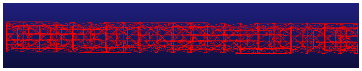
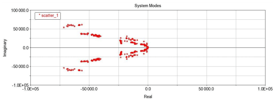
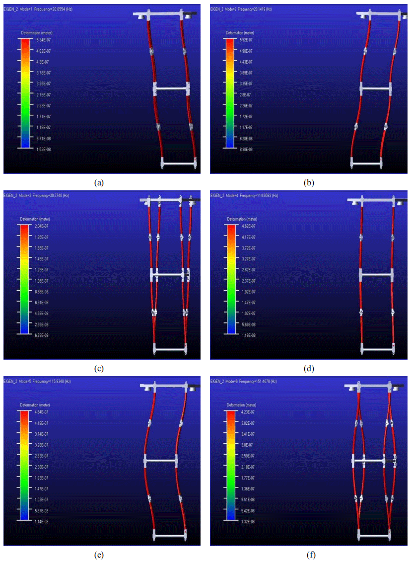
Figure 18First sixth-order vibration shape under different natural frequencies. (a) First-order vibration shape. (b) Second-order vibration shape. (c) Third-order vibration shape. (d) Fourth-order vibration shape. (e) First-order vibration shape. (f) Sixth-order vibration shape.
3.3 Modal analysis
One important way to conduct structure optimum design is to obtain a system's natural characteristics, including natural frequency and vibration shape. Before starting modal analysis, all components need to be set as flexible parts, and the wall thickness is chosen as a variable. Figure 16 shows the meshed model under a fully deployed condition, and the folded meshing model can be obtained in the same way.
3.3.1 Frequency response analysis under the folded condition
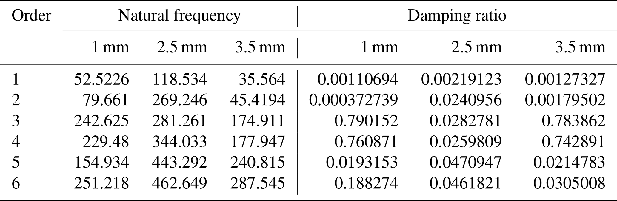
Table 1 shows the frequency and damping ratio of the structure with different wall thicknesses under the folded condition. It should show that, according to the design specification, the first-order natural frequency should be no less than 115 Hz, and the only available design with the available wall thickness is 2.5 mm.
Table 1Frequency and damping ratio with different wall thicknesses under the folded condition.
3.3.2 Frequency response analysis under the fully deployed condition
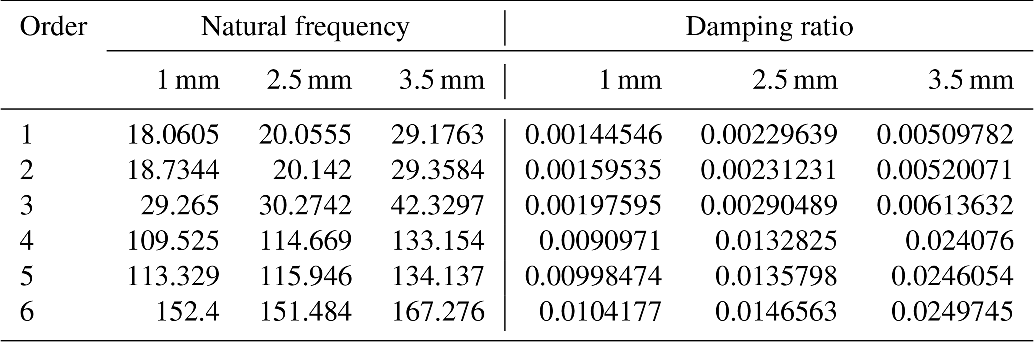
Table 2 shows the frequency and damping ratio of the structure with different wall thicknesses under the fully deployed condition. Similarly, under the fully deployed condition, the first-order natural frequency should be no less than 20 Hz. It can be found that, according to Table 2, the available design with proper wall thicknesses is 2.5 and 3 mm, respectively.
Table 2Frequency and damping ratio with different wall thicknesses under the unfolded condition.
3.3.3 Vibration shape response analysis under the fully deployed condition
According to Sect. 3.2.1 and 3.2.2, it could be that the first-order natural frequency under the folded condition is much higher than the fully deployed condition, which also means that the mechanism could generate high vibration at low frequency. So, the fully deployed condition becomes the key research object in this section.
Figure 17 shows the modal distribution diagram, and Fig. 18 shows the vibration shape under the first sixth-order natural frequency excitation. It can be seen that, in Fig. 18a and b, the deployment mechanism swings as one part in two horizontal directions. When the system is at high-level natural frequency excitation, system vibration changed into twist or higher-level swing.
In this paper, a box-structured satellite-unfolding mechanism with a brand-new self-actuated torsion joint is proposed, and a physical model and a dynamic equation are established. The system dynamic behavior is studied systematically, including impact dynamic analysis, harmonic response analysis, and modal analysis. The analysis enables us to draw the following conclusions.
-
The system could generate a sharp peak reaction force value when the load base reaches the limiting position during the process of unfolding. After the main impact, several sub-peak forces followed and went into a stable state finally, which shows that the first-order main impacting force is the key parameter for checking whether the additional joint damper is needed.
-
The harmonic responses of the load base and connecting rod in the folded and fully deployed states are seen, and the wall thickness is set as a structure optimization variable. The result shows that the system generates a high vibration magnitude at low-frequency excitation when the mechanism is in the fully deployed state and at high-frequency excitation when the mechanism is in the folded state.
-
The first sixth-order natural frequency and vibration shape with different wall thicknesses are obtained by modal analysis. The result shows that only with a 2.5 mm wall thickness can the connecting rod satisfy the design requirement.
-
The static and dynamic test research is scheduled to be conducted in a space-like center to verify the validity of the theoretical research, and the fatigue life, as the most important parameter, will be tested and researched based on the previous static and dynamic study. Additionally, the dynamic behavior research with more rod thicknesses will be studied in future work.
The data used to support the findings of this study are included within the article and are accessible on request to the corresponding author.
DS performed the methodology and formal analysis, wrote the original draft, and acquired the funding. RM performed the formal analysis and data curation. CS carried out the writing, review and editing.
The contact author has declared that none of the authors has any competing interests.
Publisher's note: Copernicus Publications remains neutral with regard to jurisdictional claims made in the text, published maps, institutional affiliations, or any other geographical representation in this paper. While Copernicus Publications makes every effort to include appropriate place names, the final responsibility lies with the authors.
This work is supported by the National Key Laboratory of Science and Technology on Helicopter Transmission (Nanjing University of Aeronautics and Astronautics) (grant no. HTL-O-20K01) and the Changzhou Science and Technology Planning Project (grant no. CE20225067).
This research has been supported by the National Key Laboratory of Science and Technology on Helicopter Transmission (Nanjing University of Aeronautics and Astronautics) (grant no. HTL-O-20K01) and the Changzhou Science and Technology Planning Project (grant no. CE20225067).
This paper was edited by Daniel Condurache and reviewed by two anonymous referees.
Angeletfi, F., Gasbarri, P., and Sabatini, M.: Optimal design and robust analysis of a net of active devices for micro-vibration control of an on-orbit large space antenna, Acta Astronaut., 164, 241–253, 2019.
Arita, S., Fukuta, I., and Yamagiwa, Y.: A proposal of new deployable space structure applying buckling, in: AIAA SciTech Forum, Kissimmee, Florida, USA, 8–12 January 2018, 2018 AIAA/ASCE/AHS/ASC Structures, Structural Dynamics, and Materials Conference, https://doi.org/10.2514/6.2018-1952, 2018.
Choi, J., Lee, D., and Hwang, K.: Design fabrication and evaluation of a passive deployment mechanism for deployable space telescope, Adv. Mech. Eng., 11, 1–14, 2019.
Cui, Y. and Tang, Y.: The in-orbit core test of Shijian-20 satellite has been completed, Space International, 7, 38–41, 2020.
Datashvili, L.: Foldability of hinged-rod systems applicable to deployable space Structures, Ceas Space Journal, 5, 157–168, 2013.
Eacre, D. and White, S.: ST8 validation experiment: ultraflex-175 solar array technology advance: deployment kinematics and deployed dynamics ground testing and model validation, in: 48th AIAA Aerospace Sciences Meeting Including the New Horizons Forum and Aerospace Exposition, Orlando, Florida, USA, 4–7 January 2010, 1497, American Institute of Aeronautics and Astronautics, Inc., https://doi.org/10.2514/6.2010-1497, 2010.
Gao, M. X., Liu, R. Q., and Li, B. Y.: Design and optimization of space deployable tri-prism mast, Journal of Vibration Engineering, 56, 129–137, 2020.
Guan, S., Pu, H. L., and Sun, W.: Application of domestic ultra-thin aluminum honeycomb material on solar array substrate, Aerospace material and technology, 53, 37–41, 2023.
He, T. Y., Dong, Y., and Wang, H.: Design and optimization of the modular parabolic deployable mechanism, Journal of Beihang University, 49, 2473–2481, 2021.
Hu, W. L., Xue, X. Z., and Chen, Y. L.: Review and analysis of the history of American international space cooperation, Space International, 08, 39–43, 2022.
Jian, S. K. and Ce, G.: Design and dynamic analysis of space deployable mechanism, Mechanical Science and Technology for Aerospace Engineering, 39, 150–156, 2020.
Liu, R. W., Guo, H. W., and Liu, R. Q.: Structural design and optimization of large cable-rib tension deployable antenna structure with dynamic constraint, Acta Astronaut., 151: 160–172, 2018.
Ma, X. F., Li, Y., and Xiao, Y.: Development and tendency of large space deployable antenna reflector, Space Electronic Technology, 15, 16–26, 2018.
Medzmarlashvili, N., Medemariashvile, E., and Tsigna, D.: Possible options for jointly deploying a ring provided with v-fold bars and a flexiblepre-stressed center, Ceas Space Journal, 5, 203–210, 2013.
Meguro, A., Hironori, I., and Tsujihata, A.: Study on ground verification for large deployable modular structures, J. Spacecraft Rockets, 43, 780–787, 2006.
Sahn, M. H., Guo, H. W., and Liu, R. Q.: Design and analysis of a triangular prism modular deployable mast, Chin. J. Mech. Eng., 31, 1–10, 2018.
Spence, B., White, S., and Jones, A.: Ultraflex-175 solar array technology maturation achievement for NASA's new millennium program space technology, The 4th World Conference on Photovoltaic Energy Conference, Waikoloa, HI, USA, May, 7–12 May 2006, IEEE, 1–8, https://doi.org/10.1109/WCPEC.2006.279879, 2006.
Wang, B., Pi, G., and Chen, W. C.: Deep learning-based surface defect detection method of flexible solar array hinge, Air & Space Defenses, 6, 96–101, 2023.
Yang, H., Guo, H. W., and Wang, Y.: Dynamic analysis and optimization for double-layer tape-spring hinge sun folding, Journal of Vibration and Shock, 35, 20–28, 2016.
Yang, H., Guo, H. W., and Wang, Y.: Design and experiment of triangular prism mast with tape-spring hyper elastic hinges, Chin. J. Mech. Eng., 31, 35–44, 2018.