the Creative Commons Attribution 4.0 License.
the Creative Commons Attribution 4.0 License.
A path-planning algorithm for autonomous vehicles based on traffic stability criteria: the AS-IAPF algorithm
Minqing Zhao
Xuan Li
Yuming Lu
Hongxi Wang
Shanping Ning
Urban traffic congestion, obstacle avoidance, and driving efficiency are the challenges faced by autonomous-vehicle path-planning technology in cities. The traditional artificial potential field (APF) algorithm is insufficient to meet the requirements of efficiency and safety in path planning, as it easily gets trapped in local optima when dealing with complex environments. Therefore, this paper proposes a novel AS-IAPF path-planning algorithm to more efficiently enhance the target reachability of autonomous vehicles in complex traffic environments. Firstly, this paper analyzes and elucidates the macroscopic traffic model, achieving effective modeling of dynamic traffic flow stability based on Lyapunov stability theorem and a classical 1D flow model. Thus, the threshold discriminant formula for traffic element stability is obtained. Secondly, based on the aforementioned threshold discriminant formula, a new AS-IAPF algorithm is proposed. The algorithm mainly includes two aspects: firstly, by pre-generating initial paths and introducing a Gaussian oscillation coefficient of force fields, it avoids the algorithm falling into local optima; secondly, by using the aforementioned driving stability threshold discriminant formula as a dimensional adjustment for adaptively improving and adjusting the strength coefficient of the AS-APF repulsive field, the algorithm further improves the efficiency of path planning. Finally, the algorithm is subjected to joint simulations of 2D and 3D scenarios of different types. The research results show that the AS-IAPF algorithm outperforms other algorithms of the same type with respect to comprehensive performance based on multiple 2D scenario simulation experiments. In the 3D simulation experiments of three different typical traffic scenarios, the proposed algorithm can drive autonomous vehicles to effectively perform corresponding obstacle avoidance actions based on the actual traffic scenarios ahead, ultimately achieving safe obstacle avoidance. The path-planning method proposed in this paper can enhance driving efficiency while considering the safety and stability of vehicles, providing a promising approach and reference for the path planning of autonomous vehicles.
- Article
(3793 KB) - Full-text XML
- BibTeX
- EndNote
Autonomous vehicles refer to vehicles that operate automatically and safely without human intervention, relying on artificial intelligence, sensors, communication devices, and GPS systems (Goerzen et al., 2009; González et al., 2016). Path-planning technology is an important technique for autonomous vehicles to navigate safely and efficiently by avoiding obstacles, such as pedestrians, vehicles, and objects (MahmoudZadeh et al., 2018; Wang et al., 2018). Compared with other automated devices, autonomous vehicles face a more complex driving environment, including the movement of pedestrians and vehicles changing lanes. These factors greatly challenge the decision-making capabilities in the path-planning process of autonomous vehicles. Incorrect judgments can lead to traffic accidents and even casualties. Therefore, it is crucial to improve the safety threshold and obstacle avoidance capabilities of autonomous vehicles in complex traffic scenarios and environments. Extensive research has been conducted to enhance the safety and efficiency of path-planning techniques. Various path-planning algorithms have been proposed, such as the dynamic window (DW) method (Wang et al., 2024), grid search method (GSM) (Tunçel, 2024), rapidly exploring random tree (RRT) (Cui et al., 2024), probabilistic roadmap (PRM) method (Zheng et al., 2024), and artificial potential field (APF) algorithm (Szczepanski, 2023). Among them, the APF algorithm is widely used and stems from the concept of physical force fields. Due to its simplicity, intuitiveness, and real-time performance, it has been extensively applied to solve obstacle avoidance and autonomous-navigation problems for robots and vehicles, and it has become a promising technical solution in certain scenarios. However, there are still four unresolved issues in the existing work on the APF algorithm that limit its large-scale industrial application. First, it does not completely eliminate potential safety hazards during obstacle avoidance. For example, the APF algorithm sometimes fails to ensure a safe distance during the driving process. Second, the APF algorithm exhibits overly conservative driving behavior in simple environments (such as static environments and strictly unidirectional fast lanes), resulting in low driving efficiency. Third, numerous studies have shown that the obstacle avoidance effect of the APF algorithm is unstable, particularly in specific scenarios where it easily falls into local optima, leading to unreachable targets. Finally, the position and velocity data of obstacle vehicles collected by the integrated vehicle-to-infrastructure platform are not fully utilized.
Consequently, in recent years, many scholars have conducted in-depth and extensive research and exploration to address the aforementioned shortcomings of the APF algorithm. Yang et al. (2023) improved the original artificial potential field (APF) algorithm by introducing four measures: selecting and delineating priority planning areas, implementing an adaptive step-size adjustment algorithm, proposing a multi-objective model considering obstacle size and impact range, and enhancing the potential field function. This resulted in an improved multi-objective APF algorithm. However, the algorithm mechanism of finding and selecting areas with fewer obstacles as the priority planning area for path planning will reduce the computational efficiency of the algorithm. Additionally, the non-linear relationship between the selected threshold and the actual driving state is not clearly explained, making it difficult to determine (Yang et al., 2023). Liu et al. (2024) designed an improved artificial potential field uncrewed aerial vehicle (UAV) path-planning algorithm (G-APF) guided by a rapid exploration random tree (RRT) based on an environmental perception model. This algorithm first generates a rough flight path for the UAV using the RRT algorithm and then uses the G-APF algorithm to solve the problems of local minima and target inaccessibility generated by the APF algorithm, as well as local trajectory oscillation. However, due to the inherent deficiencies of the RRT algorithm, it has poor robustness and low computational efficiency with respect to generating rough paths. Furthermore, this research does not provide a detailed discussion on maintaining the obstacle avoidance distance (Liu et al., 2024). Kong et al. (2023) proposed a novel B-APFDQN algorithm that combines deep Q-network and APF algorithms to address the slow convergence issue caused by the intelligent agent's frequent trial-and-error learning during the path-planning process. However, the computational efficiency and predictability of this algorithm depend on continuous training and optimization of environmental data. As the data scale increases, the algorithm's performance improves, but so does the computational workload, time consumption, and the difficulty of deploying the model (Kong et al., 2023). Y. F. Zhang et al. (2023) addressed the non-convex optimization problem in APF path planning by proposing the adaptive clustering proximity path planning (ACPP) algorithm. The advantages of the ACPP algorithm lie in its high computational efficiency, significant reduction of sample quantity, and ability to easily utilize grid-based strategies to further reduce time complexity from the segment-based map obtained from sensors. However, the research found that this algorithm performs poorly with respect to maintaining obstacle avoidance distance technical indicators. Additionally, the paper does not discuss the solution algorithm for this updating method nor provide a detailed analysis of the optimization model (Y. F. Zhang et al., 2023). Similarly, Sun et al. (2023) introduced the bug algorithm to ensure the global performance of the proposed algorithm, addressing the tendency of traditional APF algorithms to fall into local extremes. Through multiple simulations of typical scenarios, they verified the feasibility and robustness of the proposed hybrid planning algorithm. However, in practical scenarios that are constantly changing, the bug function cannot always guarantee the algorithm's global performance when considering obstacle movement and irregular shapes (Sun et al., 2023). Li et al. (2024) proposed a novel artificial potential field enhanced improved multi-objective snake optimization algorithm (APF-IMOSO). They enhanced the algorithm by optimizing and introducing four fitness functions – optimizing path length, safety (evaluated through the artificial potential field method), energy consumption, and time efficiency – to address issues with premature convergence and lack of path diversity. They conducted static and dynamic tests to demonstrate the algorithm's effectiveness. However, an investigation revealed a series of limitations in this study that restrict its application, including reduced algorithm efficiency in large-scale environments, high memory overhead during fitness function calculation, and excessive computational complexity depending on the environment (Li et al., 2024).
Based on the foundation and limitations of the aforementioned research, this paper proposes an autonomous vehicle path-planning algorithm called advance stability improved APF (AS-IAPF). The algorithm first utilizes global sampling to pre-generate paths. It then uses the obstacle vehicle's stability threshold as a dimensional adjustment parameter to adaptively improve and adjust the repulsion field strength coefficient in AS-IAPF. Additionally, a Gaussian oscillation strength coefficient is introduced to the resultant force field. Results from multiple simulation experiments demonstrate that, compared with similar products, the AS-IAPF algorithm not only maintains high efficiency but also enhances the safety performance of path planning. The principles presented in this paper illustrate that the algorithm can effectively enable autonomous cars to operate in complex environments.
The organizational structure of this paper is as follows: Sect. 1 elaborates on the significance and research status of this study; Sect. 2 presents the problem statement and model establishment for path planning; in Sect. 3, traffic stability is modeled and solved, and a threshold for stability discrimination is proposed; Sect. 4 introduces the novel AS-IAPF algorithm; in Sect. 5, joint simulation tests are conducted to verify the effectiveness and superiority of the AS-IAPF path-planning algorithm; and the final section contains the conclusion, limitations of the research, and prospects for future work.
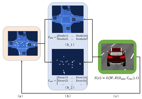
This paper assumes that the model is established under the V2X (vehicle-to-everything) scenario in urban road environments with good lighting conditions, complete and clear transmission of image and video signals, and well-maintained vehicle technical architecture (Zhong et al., 2017). Figure 1 is a schematic diagram to facilitate model description.
Figure 1a presents a model of the typical scenario of vehicle motion in an urban traffic environment. The research scenario is captured using multiple sets of cameras at the end of the road, and the images are then cropped to generate an overhead view. This view is mapped onto a plane coordinate system, where the blue area represents a simplified scene map and the white dots represent obstacle vehicles moving within the map. These are described by Eqs. (1) and (2) as follows (Geraerts and Overmars, 2004):
Here, Xe represents the entire range of the vehicle motion map (as shown in Fig. 1b_1), where xe and ye denote the horizontal and vertical coordinates of this space. Xo represents the position of the main vehicle, with xo and yo representing its horizontal and vertical coordinates.
The coordinate matrix of other moving vehicles (as shown in Fig. 1b_2) differs from that of the main vehicle, representing dynamic obstacles in the driving environment. This can be represented by Eq. (3):
Here, Ccar represents the matrix of dynamic obstacles, and Xecar represents the individual units of dynamic obstacles, with the subscript numbers indicating the sequence of unit positions.
The representation matrix of static obstacles, such as road barriers, lane markings, and impassable areas, during the actual vehicle motion process can be expressed by Eq. (4):
In Eq. (4), Oobs represents the matrix of static obstacles, and Xeobs represents the individual units of static obstacles, with the subscript numbers indicating the sequence of unit positions.
Therefore, the feasible region of the vehicle can be represented by Eq. (5):
Here, xfree and yfree represent the respective horizontal and vertical coordinates of the feasible region.
For further definition of the primary vehicle state in the environment, as shown in Fig. 1c, the primary vehicle's driving state equation is denoted as S(x). The equation is expressed as follows:
In the Eq. (6), t represents time and W represents the major technical parameters of the vehicle. In this paper, the focus is primarily on the study of path-planning algorithms, while other technical parameters and algorithms will follow a specific brand's original design plan (Zhang et al., 2024). R is defined as the traffic operating environment. Specifically, the ego vehicle S(x) should effectively avoid static obstacles and other dynamic obstacle vehicles present in the environment R. The expression for R is shown in Eq. (7):
The overall objective of the work can be summarized by the following mathematical model, which will be further computed:
The goal of the above equations is to ensure that the vehicle reaches its destination efficiently and smoothly. In the equation, ℵ represents the threshold of the objective function, a very small constant indicating the ego vehicle reaching the target point; ψ(ti) denotes the path at each moment; xinit and xgoal are the initial and final points, respectively; ψ(t0) and ψ(te) represent the initial and final elements of the path; vobs and θobs are the speed and angular displacement of other driving vehicle units, respectively; and vlimt and θlimt are thresholds for these two values. This threshold will be discussed in detail in Sect. 3.
The APF algorithm does not fully consider the global driving environment, resulting in lower efficiency when facing simple environments and the insufficient guarantee of a good safety distance in complex scenarios with dynamic obstacles. AS-IAPF, based on the APF algorithm, introduces a stability threshold for driving and employs it as a dimensional scale for the adaptive adjustment of the force field coefficients, enabling autonomous vehicles to better interpret the current environment. This section will elaborate on the modeling method for the stability of traffic elements and the calculation method for determining the threshold.
3.1 Stability evaluation methods of traffic elements
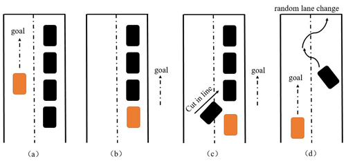
The principles of traffic stability are described in Fig. 2, considering the use of four common traffic scenarios for illustration. In Fig. 2a and b, the main flow of vehicles in the lane is high, but the vehicles are arranged in an orderly manner. However, as shown in Fig. 2c and d, there are unstable factors in the main vehicle lane (such as congestion due to other vehicles or frequent lane changing by vehicles in the same direction). The former two scenarios do not require excessive concern regarding the safety issues of path planning and are, thus, defined as having relatively good traffic element stability. On the other hand, the latter two scenarios, if safety driving distances are not considered, may lead to collisions and other traffic accidents; thus, they are defined as having relatively poor traffic element stability. Therefore, based on the actual driving conditions and scenarios mentioned above, it is necessary to further propose a new method for evaluating vehicle stability on top of traditional path planning. This aims to provide guidance for route-planning implementation, with the goal of enhancing both the driving efficiency and safety of route planning (Zhao et al., 2018).
3.2 Macroscopic dynamic model of traffic flow
In order to accurately describe the vehicle flow in unstable traffic scenarios (as shown in Fig. 2c and d) for the analysis of vehicle stability, this paper aims to establish a mathematical model based on the vehicle flow conditions.
The model is established based on the Lyapunov stability theorem and the 1D flow dynamics model by Aw and Rascle (as outlined in Jiang et al., 2010). Firstly, the 2D flow dynamics model (Aw–Rascle model) is proposed as shown in Eqs. (9), (10), and (11) (Jiang et al., 2010):
In the above equations, ρ represents the traffic flow density; v and u denote the horizontal and vertical velocities of the vehicle flow, respectively; S1 and S2 correspond to the respective horizontal and vertical traffic flow densities; and Ph and Pv indicate the macroscopic strength of the traffic flow in the respective horizontal and vertical directions, as represented by Eqs. (12) and (13):
In the above equations, τ1 and τ2 represent relaxation coefficients that balance the relaxation degree of traffic flow in the respective lateral and longitudinal directions. Additionally, this paper assumes that the density in both the lateral and longitudinal directions follows a Gaussian distribution. Therefore, the density function ρ(x,y) is given by Eq. (14):
where ρmax represents the extreme value of density, while a and b are real numbers.
Based on the above settings, the macroscopic traffic flow model is simplified to the following (Dong et al., 2020):
Here, is denoted as S1, and is denoted as S2, where Ve and Ue represent the nominal speeds in the horizontal and vertical directions of traffic flow, respectively.
3.3 Criteria for traffic flow stability
Assuming that the state variables of the vehicles and the equilibrium state variables of the traffic flow are denoted as and , respectively, if the traffic flow is stable, the spatial state is bounded as shown in the following expressions:
Therefore, the steady state of traffic flow can be described by Eqs. (22) and (23):
3.4 Analysis of traffic flow stability and thresholds
As shown in Eqs. (22) and (23), in reality, the traffic environment remains stable when the leading vehicle travels in a straight line while the following vehicle maintains orderly movement within the entire traffic flow. Under normal lane-changing conditions (equivalent to a small disturbance to the system), the traffic flow gradually returns to a stable state (asymptotically stable). However, when there is extensive lane changing or rapid merging of vehicles ahead (equivalent to a large disturbance to the system), the traffic flow loses its stability. In other words, the traffic flow can only maintain stability when the speed and angles of the traffic matrix are within certain ranges, as proposed in the fundamental concept of traffic flow stability in Fig. 2.
Based on the above idea, rearranging and expanding Eqs. (15)–(17) and computing the results yields Eqs. (24)–(26):
Simultaneously, taking the total derivative of the equations for , v(x,t), and u(y,t) yields the following respective results:
The determinant of the matrix can be obtained from Eqs. (24)–(29) and is given by Eq. (30):
By solving Eq. (30), the characteristic velocities, vc and uc, are obtained:
The eigenvalues vc and uc should satisfy Eqs. (33) and (34), respectively (Zhao et al., 2020):
Therefore, the stability thresholds for velocity in the horizontal and vertical directions are as follows:
Thus, the stable speed and angle thresholds of traffic elements can be expressed by Eqs. (39) and (40):
According to the model derivation and calculation, it can be inferred that the traffic factor is unstable when the velocity of a traffic factor exceeds or the rate of change in the turning angle exceeds dθ. These thresholds will be considered in the subsequent algorithm construction process.
The AS-IAPF algorithm improves upon the APF algorithm by pre-generating initial paths and implementing Gaussian random oscillations. Additionally, by introducing the traffic stability threshold discriminant derived from the analysis in Sect. 3.1 as the adaptive adjustment factor for the force field, the algorithm enhances its environmental perception capabilities. This effectively improves the algorithm's robustness and computational efficiency.
4.1 Pre-generating the initial path
Generating an initial path helps provide more force field information, improves planning efficiency, and further reduces the safety risks of obstacle avoidance. Therefore, prior to force field planning, the initial path is generated based on static obstacles. The main principle of generating the initial path is to use the starting point of the host vehicle as the axis and search its surrounding eight sub-nodes (Y. Zhang et al., 2023). The evaluation function f(n) for the eight sub-nodes is calculated, with the evaluation function defined as follows:
where g(n) represents the actual cost from the starting point to the current node and h(n) is the heuristic function representing the estimated cost from the current node to the target point. The formulas for the aforementioned variables are given in Eqs. (42) and (43):
where xstart and ystart are the coordinates of the starting point, xgoal and ygoal are the coordinates of the end point, and xn andyn are the coordinates of the current node.
Finally, through the search calculations until the goal point is reached, the algorithm concludes. Then, by searching backward from the goal point along the parent nodes to the starting node, the path with the minimum cost is obtained as the final path, which is used as the initial path for AS-IAPF.
4.2 Construction of force fields
In this section, we will elaborate on the process of constructing force fields. The forces at each position are calculated based on the obstacles and target points within the environment. The vehicle is then driven towards the target point along the negative gradient of the force field to ensure safe travel to the destination (Wu et al., 2023).
4.2.1 Attraction field
The attraction field exerts an attractive force on the vehicle, drawing it towards the target point. In this paper, the expression for constructing the attraction field is given by Eq. (44):
where Uattact(XO) represents the attractive force function; δ is the attraction adjustment parameter; Xgoal denotes the target point; XO represents the vehicle's position; and σ(XO,Xgoal) is the Euclidean distance between the vehicle and the target point, with σO as the threshold for this distance.
Taking the negative gradient of Eq. (44) yields the following derivative result shown in Eq. (45):
when , the value of the attractive force gradient is directly proportional to the distance between the vehicle and the target point. Conversely, when , the gradient value is inversely proportional to the distance. This mechanism effectively prevents excessive attraction force leading to collisions with obstacles due to excessively large distances.
Additionally, the initial path generation in Sect. 4.1 also exerts an attractive force on the vehicle, denoted by the following:
Here, ULine_attact(XO) represents the initial path attraction force, FLine_attact(XO) represents the negative gradient derivative of ULine_attact(XO), δ is the path attraction adjustment parameter, XLine denotes the points on the initial path, ε(XO,XLine) represents the Euclidean distance between the vehicle and the points on the initial path, and εO is the threshold for this distance.
4.2.2 Force field
The repulsive field exerts a repulsive force on vehicles, which can keep them away from obstacles. In this paper, the equation for the repulsive field is set as follows:
where Urepulsion(XO) is the repulsion field function; μ is the attraction adjustment parameter; Oobs represents the obstacle point; XO is the vehicle position; and γ(XO,Xgoal) is the Euclidean distance between the vehicle and the obstacle point, with γO as the threshold distance.
Furthermore, if there are n obstacle points in the scene, the total repulsion field is the vector sum of n repulsion fields, expressed as follows:
Similarly, taking the negative gradient of Eq. (49) yields the repulsive force as shown in Eq. (50):
For the repulsive field adjustment parameter μ, based on the flow stability determination method described above, the adaptive adjustment strategy for μ is given by Eq. (51):
When the obstacle vehicle is in the stable range determined by the judgment criteria, the adjustment parameter for the repulsion field remains at a constant value μo. However, when the obstacle vehicle is not in the stable range, the value of the repulsion field adjustment parameter will gradually increase according to the degree of instability of the vehicle's driving state, thereby dynamically controlling the avoidance force of the vehicle.
4.2.3 Resultant force
In conclusion, the resultant force field is obtained by adding the attraction field function and the repulsion field function as follows:
Therefore, the corresponding negative gradient of the resultant force is Eq. (53):
where ξ represents the strength of Gaussian random oscillations and Z(0,1) generates a random number from a standard normal distribution. The purpose of this component is to prevent path planning from falling into local optima.
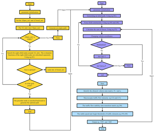
Finally, the flowchart of AS-IAPF is shown in Fig. 3. In Fig. 3, the orange part is the process of the pre-generated path algorithm, the blue part is the process of generating the stability threshold of traffic elements, and the purple part is the force field construction process of the AS-IAPF algorithm.
This section presents the results of five experiments to demonstrate the effectiveness of the proposed AS-IAPF algorithm. The five experiments consist of five 2D trials and one 3D trial. The five 2D scenarios include four static obstacle avoidance scenarios and one dynamic obstacle avoidance scenario, while the 3D trial encompasses three typical traffic scenarios. The experimental scenarios comprehensively cover various obstacle avoidance situations, providing multiple perspectives on the effectiveness of the AS-IAPF algorithm with respect to addressing issues related to algorithm entrapment in local optima and low efficiency in dynamic obstacle avoidance. Comparative experiments significantly indicate that the proposed algorithm performs well in various specific environments.
5.1 Experiment 1
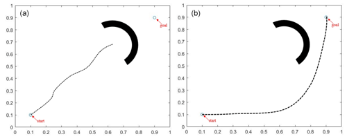
The first experiment simulates the process of vehicle obstacle avoidance when faced with a semicircular obstacle, which notably features several local optimal points (i.e., points where the resultant force field, as indicated in Eq. 52, equals 0). In the experiment, the starting point is set at (0.1,0.1), while the target point is set at (0.9,0.9). The results of the experiment are shown in Fig. 4. The original APF algorithm, when faced with this type of obstacle, easily falls into local optima due to the lack of a priori initialization path guidance and oscillation processing of the force field. In contrast, the AS-IAPF algorithm effectively avoids local optima and reaches the target point. The results of 100 repeated simulation trials are presented in Table 1.
As indicated in Table 1, the results of 100 repeated simulation trials demonstrate that the AS-IAPF algorithm exhibits an average planning time of 5.69 s and an average path length of 2.37 cm. Compared with the original APF, these values represent improvements of 20.86 % and 5.58 %, respectively. Furthermore, due to the propensity of APF to fall into local optima in this scenario, AS-IAPF achieves a 100 % success rate in optimization.
5.2 Experiment 2
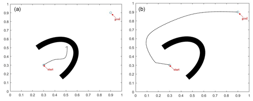
Experiment 2 involved a static U-shaped obstacle. In contrast to Experiment 1, the local optimal region of the U-shaped obstacle is larger than that of the semicircular obstacle, and the starting point is positioned within the U-shaped obstacle. The starting point is set at (0.3,0.3), while the target point is set at (0.9,0.9). The results of the experiment are depicted in Fig. 5. The standard APF algorithm occasionally shows the vehicle driving in the wrong direction, whereas the AS-IAPF algorithm, benefiting from prior path planning, consistently and successfully reaches the target point.
To further demonstrate the superiority of the proposed algorithm, the results of 100 repeated simulation trials in the same scenario are presented in Table 2.
As shown in Table 2, the results of 100 repeated simulation trials for Scenario 2 indicate that the AS-IAPF algorithm has an average planning time of 10.31 s and an average path length of 4.19 cm. Compared with the original APF, these metrics represent improvements of 19.89 % and 3.89 %, respectively. Furthermore, in terms of the optimization success rate, the AS-IAPF algorithm achieves a success rate of 100 % due to its a priori strategy, whereas the original APF algorithm is prone to falling into local optima, with an average success rate of only 79 %.
5.3 Experiment 3
Experiment 3 features a small yet complex maze-like map with multiple rectangular obstacles and numerous local optimal points. The map measures 500 units × 500 units, with the starting point set at (50,50) and the end point at (450,450). Figure 6 presents the final computation results for five different algorithms.
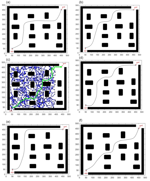
Figure 6Diagram of results for Experiment 3: (a) AS-IAPF, (b) DA-APF, (c) RRT, (d) GA, (e) PRM, and (f) APF.
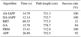
To intuitively display the performance of the algorithms in this environment, this study conducted 100 simulations of the aforementioned six algorithms (Wu et al., 2023) in this static environment and averaged the results, which are listed in Table 3.
From the experimental statistical results in Table 1, it is evident that, in terms of target reachability, both AS-IAPF and DA-IAPF, as well as the PRM algorithm, achieved a 100 % success rate. Regarding time, AS-IAPF was 5.3 % slower than DA-IAPF but improved by 4.02 % compared with PRM. In terms of path length, AS-IAPF was 1.17 % longer than PRM and 1.58 % longer than DA-IAPF. The quantitative experimental results demonstrate that the PRM algorithm provides the shortest route; however, under the evaluation criteria of this study, AS-IAPF exhibits higher solution quality. This is primarily reflected in the following aspects: (1) fewer vehicle turns result in smoother vehicle trajectories, (2) vehicles maintain a better safety distance from obstacles during travel, and (3) the algorithm demonstrates the best overall efficiency. Therefore, it can be inferred that, although there is still room for optimization in the AS-IAPF algorithm and minor differences in related performance indicators, the algorithm exhibits good overall performance and can meet the path-planning requirements of static complex obstacle avoidance environments.
5.4 Experiment 4
Experiment 4 simulated the performance of vehicles when facing stationary and moving vehicles. Two scenarios were set up. Firstly, the transformation of the Cartesian coordinates in Eqs. (3) and (4) into Frenet coordinates was required, and the vehicle's dynamics equations were then established based on Eq. (6) after the coordinate transformation (Li et al., 2022).
5.4.1 Scenario 1
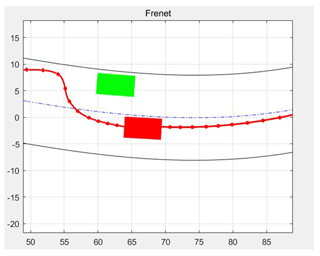
There is a parked vehicle by the roadside (represented by a green rectangular box in Fig. 7). The ego vehicle (red rectangular box) is driving behind the obstacle, with sufficient lateral space to avoid the side obstacle. The simulation results for this scenario are shown in Fig. 7. According to the results, the minimum distance between the ego vehicle and the obstacle is 3.29 m. As shown in Fig. 7, at each 1 s time step, the potential field forces the vehicle away from the obstacle and the road boundary to avoid collisions. After passing the obstacle, the ego vehicle continues to travel along the adjacent lane. From the simulated trajectory, it is observed that the yaw angle remains within a reasonable range at all times.
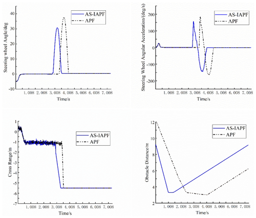
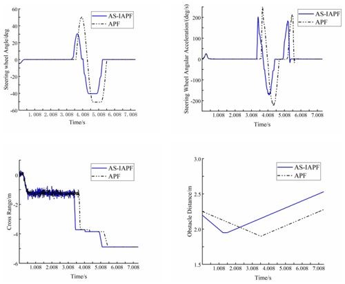
APF and AS-IAPF were run separately in Scenario 1, and the temporal data of four parameters – steering angle, steering angular acceleration, lateral displacement, and Euclidean distance to the obstacle – were compared (Zheng et al., 2014; Li et al., 2021). The temporal data of the experimental results are shown in Fig. 8. A comparison revealed that, in this scenario, AS-IAPF improved obstacle avoidance time by 12.5 % compared with APF, indicating increased efficiency. The maximum steering angle decreased by 16.8 %, steering angular acceleration decreased by 14.04 %, and the slope of lateral displacement significantly decreased, indicating smoother vehicle operation. The minimum distance between the vehicle and the obstacle was 3.29 m, while the minimum distance for APF under the same conditions was 3.02 m, demonstrating an 8.94 % increase in safety distance, signifying safer vehicle operation.
5.4.2 Scenario 2
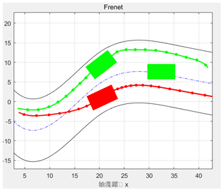
Scenario 2 aimed to demonstrate a simulation experiment of lane changing by the ego vehicle in the presence of both moving obstacle vehicles and stationary vehicles on a predetermined dual-lane curved road. Figure 9 displays the simulation results for this scenario, with each time step between two red points being 1 s. During the avoidance process, the minimum distance between the two vehicles was 1.5 m. The final results indicate that the ego vehicle was able to reach the destination safely.
The experimental results for Scenario 2 are shown in Fig. 10: in terms of obstacle avoidance time, AS-IAPF was 5.2 % shorter than APF; in terms of steering angle, AS-IAPF was 1.59 % smaller than APF; in terms of steering angular acceleration, AS-IAPF was 19.83 % smaller than APF; and in terms of safety distance, AS-IAPF was 14.49 % longer than APF. In summary, the data from both scenarios reflect that, in the same obstacle avoidance scenario, the AS-IAPF algorithm demonstrates varying degrees of improvement with respect to driving efficiency, safety, and smoothness compared with the APF algorithm.
5.5 Experiment 5
Given the satisfactory computational performance of the aforementioned four 2D simulation environments, the obstacle avoidance performance of the AS-IAPF algorithm was further validated. This work involved a 3D simulation experiment based on real traffic scenarios to verify its performance (Cao et al., 2024).
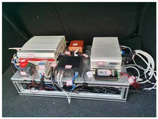
To obtain actual traffic scenarios, data were collected from a real traffic scene in a city in China using a specialized data collection vehicle equipped with a four-line laser radar, an intelligent camera, two sets of high-definition (HD) cameras, two sets of regular cameras, a data collection engineering vehicle, a data collection system, a touch screen, a comprehensive navigation system, and a controller area network (CAN), among other equipment. The hardware equipment for the data collection engineering vehicle and the data collection system is shown in Fig. 11.
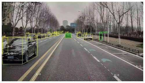
During the scene collection process, the data collection vehicle travels on the road to be surveyed. The data collection engineering vehicle and the data collection system are capable of real-time recognition and collection of various vehicles and obstacles on the road surface based on the actual traffic scenarios. This information is then stored as a 3D digital scene in the system. The real-time images collected are shown in Fig. 12 (Zou and Liang, 2024).
After collecting data from real-world traffic scenarios, this study incorporated the dynamics models and other technical parameters of a certain Chinese-manufactured autonomous vehicle (such as the state equation shown in Eq. 4) into a digital model. Following adjustments and improvements to the relevant dynamics models, the proposed path-planning algorithm was implemented in a simulator. Three simulation scenarios were generated in the scenario system: static obstacles, abruptly braking vehicles, and moving vehicles, aimed at validating the algorithm's comprehensive obstacle avoidance performance.
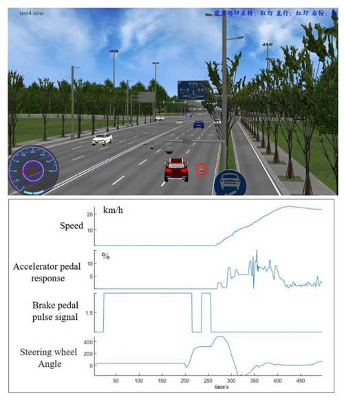
The simulation test results include experimental-scenario data and real-time vehicle operational data. The real-time data results comprise the following: vehicle speed, accelerator pedal response signal, steering wheel angle signal, and brake pedal pulse signal. The brake pedal pulse signal serves as a state variable (1 indicates vehicle braking initiation, while 0 indicates cessation of vehicle braking). Figure 13 depicts the obstacle avoidance scenario with static obstacles, where a static, conical-barrel obstacle is set in the scene. Real-time data curves show that the vehicle comes to a stop in front of the fixed obstacle for a period; the steering wheel angle gradually increases; the vehicle automatically changes lanes to the right to avoid the obstacle; and, after successful avoidance, the speed gradually increases as it returns to the normal lane. Experimental results in this scenario demonstrate the algorithm's effectiveness with respect to avoiding stationary obstacles.
As shown in Fig. 14, the simulation test presents the scenario of sudden braking by the preceding vehicle for obstacle avoidance. The blue vehicle ahead abruptly stops, triggering a brake pulse response signal in the host vehicle to reduce speed. Simultaneously, the steering wheel angle signal increases, enabling the host vehicle to smoothly yield and change lanes to the right. Following the successful lane change, the steering wheel angle signal returns to normal, and the vehicle merges back into the regular lane. Experimental results in this scenario affirm the algorithm's effectiveness in the event of sudden braking by the preceding vehicle.
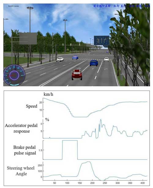
Figure 14Simulation test of obstacle avoidance in the case of sudden braking in front of the host vehicle.
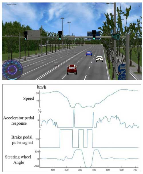
Illustrated in Fig. 15 is the simulation test for obstacle avoidance with a preceding vehicle moving at a constant speed. As the blue vehicle ahead travels forward at a constant speed, the host vehicle follows behind in the same lane and direction. Upon reaching the safe distance threshold, the following occurs: the brake pedal response signal is first triggered to reduce speed; concurrently, the steering wheel angle signal causes the vehicle to change lanes to the adjacent lane; upon passing the obstacle, the vehicle then reverts back to the initial lane, ultimately successfully achieving a lane change and yielding at normal speed.
The significant testing results of the above three scenarios clearly demonstrate that, in real digitalized 3D testing environments, the algorithm is capable of achieving safe obstacle avoidance when confronted with stationary obstacles (Fig. 13), sudden braking vehicles (Fig. 14), and moving vehicles (Fig. 15), ultimately enabling the vehicle to reach its intended destination.
To (i) enhance the obstacle avoidance capabilities of autonomous vehicles in complex traffic scenarios in actual urban traffic and (ii) improve the planning computation efficiency and trajectory tracking performance of the APF algorithm, this paper proposes an AS-IAPF algorithm based on the criterion of traffic stability. This algorithm enhances the efficiency and driving safety of the APF algorithm, enabling the vehicle to make corresponding obstacle avoidance actions effectively based on the actual obstacle avoidance scenarios ahead, ultimately achieving efficient and safe obstacle avoidance. The main conclusions of this paper are as follows:
- 1.
Firstly, this study analyzes and expounds on macroscopic traffic models and achieves effective modeling of the stability of traffic elements based on Lyapunov stability theorem and classical 1D flow models, thereby obtaining a threshold discriminant for traffic stability.
- 2.
Secondly, based on the above threshold discriminant, a new type of AS-IAPF algorithm is proposed. In comparison with the standard APF, AS-IAPF introduces a threshold criterion for traffic flow stability into the standard potential field functions, which is used to adaptively adjust the repulsive field adjustment coefficient. Additionally, it guides the vehicle to the target point by using the gradient descent potential guidance strategy. Furthermore, by pre-generating an initial global path for path planning, a Gaussian oscillation factor is introduced to help the vehicle escape local minima.
- 3.
Finally, this work conducts joint simulation experiments for 2D and 3D scenarios of five different types. The simulation results indicate good performance in various static and dynamic scenarios, with a pathfinding success rate of close to 100 %. Compared with other algorithms, AS-IAPF can obtain optimal or near-optimal paths in various complex environments, exhibiting good smoothness and a safe distance without oscillation.
However, the research in this paper is not yet perfect, with existing issues including the following:
- 1.
There is still room for further improvement in the quality and efficiency of the algorithm's solution, as the algorithm fails to achieve the optimal value during operation.
- 2.
The digital traffic scenarios covered in the experiments are not comprehensive enough, especially in the face of scenarios such as pedestrians crossing the road, cars approaching from behind, and obstacle vehicles cutting in and out of traffic, which require further exploration in future work.
- 3.
This paper lacks field tests and road experiments with actual vehicles, and further research on the algorithm is needed with respect to the operational scenarios of actual vehicles, with the adaptability of the current autonomous-driving hardware and software yet to be verified.
The data and code that support the findings of this study are available upon request from the corresponding author.
In this paper, each author made significant contributions that collectively enhance the field of autonomous vehicle navigation. MZ developed the theoretical framework for the AS-IAPF algorithm, emphasizing the integration of traffic stability criteria into the path-planning process. XL conducted extensive simulations to validate the performance of the algorithm, providing a comprehensive analysis of its effectiveness under various traffic conditions. YL focused on optimizing the computational efficiency of the algorithm, ensuring its applicability in real-time autonomous driving scenarios. HW contributed valuable insights into the practical implementation of the algorithm, collaborating on field tests to assess its reliability in real-world traffic situations. Finally, SN led the evaluation of traffic stability metrics, enhancing the robustness of the algorithm by incorporating crucial safety and efficiency parameters. Together, these contributions significantly advance the understanding and application of path planning for autonomous vehicles, prioritizing both stability and responsiveness.
The contact author has declared that none of the authors has any competing interests.
Publisher's note: Copernicus Publications remains neutral with regard to jurisdictional claims made in the text, published maps, institutional affiliations, or any other geographical representation in this paper. While Copernicus Publications makes every effort to include appropriate place names, the final responsibility lies with the authors.
The completion of this paper would not have been possible without the generous support and guidance of several individuals to whom the authors owe their deepest gratitude. First and foremost, we would like to express our sincere appreciation to Xuan Li from the School of Information Science and Technology at East China Jiaotong University for his unwavering support of this research. His invaluable insights and scientific methodology greatly contributed to the development of this study.
We are also grateful to Yuming Lu from the Nanchang University of Aeronautics for his meticulous review of the language and presentation of the manuscript, which was significantly improved with respect to quality. Furthermore, we would like to extend our thanks to Hongxi Wang from the Xi'an Technological University for providing the necessary facilities and resources for the execution of this research.
Their support and expertise have been instrumental in the successful completion of this work, and, for that, we are sincerely thankful.
In addition, this work was supported by a research program funded by the major science and technology projects of Shaanxi Province, Xi'an China (grant no. 2019zdzx01-02-02); the National Natural Science Foundation of China (grant nos. 61866025 and 61861018); and, in part, by the Jiangxi Provincial Natural Science Foundation (grant no. 20212BAB212001).
This research has been supported by the National Natural Science Foundation of China's National Science Fund for Distinguished Young Scholars (grant nos. 61866025 and 61861018) and the National Science and Technology Major Project's National Transgenic Science and Technology Program (grant no. 2019zdzx01-02-02).
This paper was edited by Daniel Condurache and reviewed by Van Sy Nguyen, Mohammad Naeim Moradi, and two anonymous referees.
Cao, L. L., Feng, X. X., and Liu, J. L.: Automatic Generation System for Autonomous Driving Simulation Scenarios Based on Pre-Scan, Appl. Sci.-Basel, 14, 1354, https://doi.org/10.3390/app14041354, 2024.
Cui, X. I., Wang, C. Q., Xiong, Y., Mei, L., and Wu, S. Q.: More Quickly-RRT*: Improved Quick Rapidly-exploring Random Tree Star algorithm based on optimized sampling point with better initial solution and convergence rate, Eng. Appl. Artif. Intel., 133, 108246, https://doi.org/10.1016/j.engappai.2024.108246, 2024.
Dong, H. R., Zhou, M., and Wang, Q. L.: State-of-the-Art Pedestrian and Evacuation Dynamics, IEEE T. Intell. Transp., 21, 1849–1866, https://doi.org/10.1109/TITS.2019.2915014, 2020.
Geraerts, R. and Overmars, M. H.: A Comparative Study of Probabilistic Roadmap Planners, Algorithmic Foundations of Robotics, 4, 43–58, 2004.
Goerzen, C., Kong, Z., and Mettler, B.: A survey of motion planning algorithms from the perspective of autonomous UAV guidance, J. Intell. Robot. Syst., 57, 65–66, 2009.
González, D., Perez, J., Milanes, V., and Nashashibi, F.: A review of motion planning techniques for automated vehicles, IEEE T. Intell. Transp., 17, 1135–1145, 2016.
Jiang, Y. Q., Zhang, P., Wong, S. C., and Liu, R. X.: A higher-order macroscopic model for pedestrian flows, Physica A, 21, 4623–4635, https://doi.org/10.1016/j.physa.2010.05.003, 2010.
Kong, F. C., Wang, Q., Gao, S., and Yu, H. L.: B-APFDQN: A UAV Path Planning Algorithm Based on Deep Q-Network and Artificial Potential Field, IEEE Access, 11, 44051–44064, 2023.
Li, C. X., Lu, S. B., and Zhang, B. H.: Human-vehicle Steering Collision Avoidance Path Planning Based on Pedestrian Location Prediction, Automot. Eng., 43, 880, https://doi.org/10.19562/j.chinasae.qcgc.2021.06.011, 2021.
Li, H. C., Liu, W. J., and Yang, C.: An Optimization-Based Path Planning Approach for Autonomous Vehicles Using the DynEFW A-Artificial Potential Field, IEEE Transactions on Intelligent Vehicles, 7, 263–272, 2022.
Li, Q. L., Ma, Q. H., and Weng, X.: Dynamic path planning for mobile robots based on artificial potential field enhanced improved multiobjective snake optimization (APF-IMOSO), J. Field Robot., 41, 1843–1863, https://doi.org/10.1002/rob.22354, 2024.
Liu, J. L., Yan, Y. H., Yang, Y. H., and Li, J. L.: An Improved Artificial Potential Field UAV Path Planning Algorithm Guided by RRT Under Environment-Aware Modeling: Theory and Simulation, IEEE Access, 12, 12080–12097, 2024.
MahmoudZadeh, S., Yazdani, A., Sammut, K., and Powers, D.: Online path planning for AUV rendezvous in dynamic cluttered undersea environment using evolutionary algorithms, Appl. Soft Comput., 70, 929–945, 2018.
Sun, L. Y., Fu, Z. M., Tao, F. Z., Si, P. J., Song, S. Z., and Sun, C.: Apf-Bug-based Intelligent Path Planning for Autonomous Vehicle with High Precision in Complex Environment, Int. J. Robotics Autom., 38, 277–283, 2023.
Szczepanski, R.: Safe Artificial Potential Field-Novel Local Path Planning Algorithm Maintaining Safe Distance From Obstacles, IEEE Robotics and Automation Letters, 8, 4823–4830, 2023.
Tunçel, A.: Comparison of earthquake location parameters determined using grid search and manta ray foraging optimization, Acta Geophys., 72, 2581–2596, https://doi.org/10.1007/s11600-024-01359-7, 2024.
Wang, B. F., Li, S., Guo, J., and Chen, Q. W.: Car-like mobile robot path planning in rough terrain using multi-objective particle swarm optimization algorithm, NeuroComputing, 282, 42–51, 2018.
Wang, T., Li, A. J., Guo, D. J., Du, G. K., and He, W. K.: Global Dynamic Path Planning of AGV Based on Fusion of Improved A* Algorithm and Dynamic Window Method, Sensors-Basel, 24, 2011, https://doi.org/10.3390/s24062011, 2024.
Wu, Z., Dai, J., and Jiang, B.: Robot path planning based on artificial potential field with deterministic annealing, ISA T., 138, 74–87, 2023.
Yang, J., Zhang, H. C., and Ning, P.: Path Planning and Trajectory Optimization Based on Improved APF and Multi-Target, IEEE ACCESS., 11, 139121-139132, 2023.
Zhang, T. T., Sun, Y. S., Wang, Y. Z., Li, B., Tian, Y. L., and Wang, F. Y.: A Survey of Vehicle Dynamics Modeling Methods for Autonomous Racing: Theoretical Models, Physical/Virtual Platforms, and Perspectives, IEEE Transactions on Intelligent Vehicles, 9, 4312–4334, 2024.
Zhang, Y., Li, L., and Lin, H. C.: Development of Path Planning Approach Using Improved A-star Algorithm in AGV System, J. Internet Technol., 20, 915–924, 2023.
Zhang, Y. F., Zhang, Z. H., and Wang, S. Y.: Adaptive Clustering Quasi-Line Search Path Planning Algorithm Based On Sampling, IEEE T. Veh. Technol., 2, 1720–1734, 2023.
Zhao, G. L., Wei, W., and Wang, D. G.: Enhancement of the Variable Universe of Discourse Control by Hammersley Sequence-Based TP Model Transformation, in: 2018 Eighth International Conference on Information Science and Technology (ICIST), Cordoba, Granada, and Seville, Spain, 30 June–6 July 2018, IEEE, 9, 401–408, https://doi.org/10.1109/ICIST.2018.8426173, 2018.
Zhao, R., Liu, Q., and Hu, Q.: Lyapunov-Based Crowd Stability Analysis for Asymmetric Pedestrian Merging Layout at T-Shaped Street Junction, IEEE T. Intell. Transp., 21, 1–10, 2020.
Zheng, D. L., Ridderhof, J., Zhang, Z. Y., Tsiotras, P., and Agha-Mohammadi, A.: CS-BRM: A Probabilistic RoadMap for Consistent Belief Space Planning With Reachability Guarantees, IEEE T. Robot., 40, 1630–1649, 2024.
Zheng, S., Janecek, A., Li, J., and Tan, Y.: Dynamic search in fireworks algorithm, in: Proc. IEEE Congress Evol. Computation, Beijing, China, 3222–3229, https://doi.org/10.1109/CEC.2014.6900485, 2014.
Zhong, R. X., Chen, C., Huang, Y. P., Sumalee, A., Lam, W. H. K., and Xu, D. B.: Robust perimeter control for two urban regions with macroscopic fundamental diagrams: A control-Lyapunov function approach, T. Res. Proc., 23, 922–941, https://doi.org/10.1016/j.trpro.2017.05.051, 2017.
Zou, L. and Liang, T. H.: Algorithm Optimization of Computer Simulation Vehicle Driving Simulation System Based on Virtual Reality Technology, Int. J. Comput. Int. Sys., 17, 34, https://doi.org/10.1007/s44196-024-00426-7, 2024.
- Abstract
- Introduction
- Model statement and establishment
- Math traffic stability modeling and thresholding
- AS-IAPF algorithm
- Experiment and simulation
- Conclusion
- Code and data availability
- Author contributions
- Competing interests
- Disclaimer
- Acknowledgements
- Financial support
- Review statement
- References


