the Creative Commons Attribution 4.0 License.
the Creative Commons Attribution 4.0 License.
 | 03 Sep 2024
Task-driven geometric synthesis method of a bistable compliant mechanism for the rigid guidance problem
Jingyu Jiang
Song Lin
Hanchao Wang
Compliant bistable mechanisms are specialized mechanisms that have specific self-locking characteristics in two positions. They are widely used in aerospace, micro-electromechanical systems, and high-precision manufacturing. The coupling of kinematic with elastomechanical behaviors of compliant mechanisms, known as kinetostatics, increases the difficulty of synthesizing compliant mechanisms. Currently, most research relies on optimization approaches to find compliant mechanisms that meet motion requirements. To address this challenge, this paper proposes a geometric synthesis method for compliant bistable mechanisms to solve the rigid guidance problem. The pole similarity transformation characteristics of planar beams and the static equilibrium characteristic of bistable mechanisms at stable positions are utilized to decouple the kinematic synthesis and static analysis. The proposed method introduces a task-driven synthesis process, where the critical structural parameters in compliant mechanisms are determined based on the desired guidance positions of motion tasks. This approach eliminates the need for a tedious and time-consuming iterative optimization process. The resulting bistable mechanisms have two stable positions that correspond to the desired guidance positions of the motion task. To illustrate the effectiveness of the geometric synthesis method, a two-position problem of a compliant bistable mechanism is provided as an example.
- Article
(7045 KB) - Full-text XML
- BibTeX
- EndNote


The synthesis of mechanisms has long been a topic of study in the field of rigid mechanisms. One classic problem in this area is the rigid guidance problem, which has been extensively researched for hundreds of years. Various efficient and accurate synthesis methods, such as the geometric method, analytical method, and atlas method, have been proposed to address this problem (McCarthy and Soh, 2010). However, when it comes to compliant mechanisms, the situation is different. The motion transmission in compliant mechanisms primarily relies on the deformation of compliant components (usually planar beams) under external forces. This unique characteristic makes it challenging to independently figure out kinematic design and static analysis, posing significant challenges in the synthesis of compliant mechanisms (Howell et al., 2013; Lobontiu, 2002).
If the length of the compliant components is similar to the length of the rigid components, the geometric nonlinearity caused by large deformation must be considered (Kimball and Tsai, 2002). At present, many method have developed to analyze the large deflection of planar beams, such as the elliptical integral method, pseudo-rigid-body model (PRBM) and beam constraint model (BCM). The elliptic integral method is a classic solution for high-precision large deformation problems of planar beams. This method originated from the elastica problem and was introduced into the analysis of compliant mechanisms to solve the large deflection problem under different tip loads (Shoup and McLarnan, 1971). Zhang and Chen (2013) have extended this method and provided a comprehensive solution of elliptic integrals for large deflection problems, which can solve the problem of multiple inflection points in compliant beam deformation. Holst et al. (2011) and others improved the accuracy of the elliptic integral method by introducing axial deflection and applying it to fixed-guidance beams. Although the final results of the elliptic integral method need to be obtained through elliptic integral tables, as an analytical solution for large deflection problems, the method provides the most accurate results for compliant beam deformation. Based on the elliptic integral method, Wang and Xu (2017) conducted an analysis of the kinetostatics of an XY micro-positioning stage with negative stiffness. Based on the results of the elliptic integral method, Midha et al. (2000) proposed a pseudo-rigid-body model (PRBM), which approximates compliant beams as a rigid link mechanism with torsion springs and decouples the kinematics and static analysis of planar beams. Howell and Midha (1994) created a synthesis approach based on PRBM, which can provide a practical means for analyzing and designing the compliant mechanisms. PRBM simplifies the geometric nonlinearity problem of compliant beams down to a very intuitive rigid mechanism model but at the cost of reducing the accuracy of motion analysis. Furthermore, several improved model, including PRBM with axial springs (Saxena and Kramer, 1998), PRBM with variable parameters (Dado, 2001), 2R PRBM (Yu et al., 2012), 3R PRBM (Su, 2009; Lin et al., 2021), and 5R PRBM (Yu and Zhu, 2017), were proposed and applied in the design of compliant mechanisms with large deflection. Various compliant mechanisms with special characteristics, including compliant beams with inflection points (Zhu and Yu, 2017), compliant beams with contact (Jin et al., 2020), three-dimensional (3D) compliant beam deformation (Chase et al., 2011), and initially curved compliant beam deformation (Kalpathy Venkiteswaran and Su, 2017), can be analyzed and designed using PRBM. Another widely used method for modeling compliant mechanism is the beam constraint model (BCM). BCM, proposed by Awtar et al. (2006), provides a closed-form model of planar beam within an intermediate deformation range. Ma and Chen (2015) proposed a chain-beam constraint model (CBCM) to solve large deformation problems based on the BCM. CBCM can obtain the displacement at each node on the planar beam, making it more suitable for general compliant mechanism design problems. Besides, the energy-minimization-based kinetostatic solutions are also used in the design of compliant mechanism. For example, Turkkan and Su (2017), Turkkan et al. (2018), and Jiang et al. (2023) have all proposed design methods for compliant mechanisms based on the principle of minimum potential energy combined with optimization methods. Chen et al. (2017) also proposed a design method for compliant mechanisms based on the Crotti–Engesser theorem.
Bistable mechanisms are a type of compliant mechanism with special energy characteristics. Within their range of motion, there are positions or deformed states with local minima of strain energy, which are referred to as the stable positions or stable equilibrium positions of the mechanism. The mechanism can remain in a stable equilibrium position without relying on external forces and can return to the stable equilibrium position after being disturbed by external forces. This self-sustaining characteristic of compliant bistable mechanisms makes them highly valuable in specific rigid guidance problems. Currently, the most common design method for bistable mechanisms is to utilize the buckling characteristic of planar beams. Sönmez and Tutum (2008) and Zhao et al. (2008) established models of bistable mechanisms with hinged and fixed connections at both ends of a buckled beam. To avoid higher-order buckling states during deformation, Qiu et al. (2004), Hussein et al. (2019), Hussein et al. (2020), and Haddab et al. (2018) proposed buckling models of curved beams and used them to create linear bistable mechanisms. In order to provide more adjustable parameters for the design of bistable mechanisms, scholars such as Parkinson et al. (2000), Chen et al. (2021), Todd et al. (2010), and Tran and Wang (2017) proposed multi-segment planar beam bistable mechanisms. Another method to obtain the desired mechanical performance of bistable mechanism is using the planar beams with special shapes based on topology optimization (Chen et al., 2019) or other optimization method (Chi et al., 2019). Building upon this, to address the issue of axial stiffness reduction after buckling of planar beams, Nathan and Howell (2003), Wilcox and Howell (2005), Han et al. (2017), and others proposed bending-torsion planar beam configurations for designing planar bistable mechanisms with linear motion. Additionally, Jiang et al. (2024) proposed a synthesis method of series-based bistable compliant mechanisms for the rigid-body guidance problem based on the geometrical similarity transformation. Sargent et al. (2020) proposed a bistable mechanism used in medical support systems based on origami. Huang et al. (2020) designed a special linear bistable mechanism which only need one actuator to switch between two stable positions.
As mentioned above, a large number of compliant mechanism design methods have proposed and successfully applied in the design of various compliant mechanisms. Most of these methods still start from the analysis of mechanisms and find the optimal mechanisms that meet the motion task requirements through numerical optimization, especially in the field of bistable mechanism design. It is still difficult to simultaneously consider the accuracy and efficiency in large-deformation compliant mechanism design, and it is even more difficult to adjust the structural parameters of the mechanism with purpose based on motion tasks. Therefore, this paper proposes a synthesis method for the compliant bistable mechanism based on the pole similarity transformation. This method utilizes the special properties in the geometric transformation process of planar beams and the static equilibrium characteristics of stable positions in bistable compliant mechanism to directly select and determine the structural parameters in compliant mechanisms according to the given motion tasks. The synthesis of compliant mechanism rigid guidance problems with two stable positions is completed through this method.
The organization of paper is as follows: Sect. 2 presents the basic theories involved in this paper, including the deformation behavior of planar beams, the solution of the poles of planar beams, and the similarity transformation characteristics of planar beams. Section 3 introduces the synthesis method for two-position bistable mechanisms, including the description of motion tasks, the solution of the mechanism's structural parameters, and the general process of bistable mechanism synthesis. Sections 4 and 5 provide a specific synthesis case, and the design results were validated through simulations and experiments. In Sect. 6, we discuss the experimental results and propose future research directions.
Planar beams are the primary elements in compliant mechanisms that transmit motion and force. This study initially determines the deformation behavior of planar beams. The motion of the beam’s tip is then described using the pole and pole angle. Lastly, the study presents the similarity transformation characteristics of the pole, which establishes the relationship between the structural parameters of planar beams and the motion of the beams' tips.
2.1 Analysis of planar beam's deformation behavior
The deformation of the planar beam in this paper is based on the Bernoulli–Euler beam theory, in which the relationship between the sectional bending moment and the beam curvature of the planar beam is as follows:
where Mb represents the bending moment of the cross section, represents the angular deformation rate (curvature) along the beam, E represents Young’s modulus of the material, and I represents the moment of inertia of the beam. The curvature, κ, can be further calculated by the deformation of a flexible beam as follows:
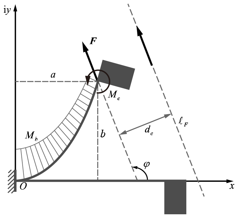
As shown in Fig. 1, for a planar beam subjected to concentrated loads and bending moments at the beam's tip, the sectional bending moment on the beam can be calculated using loads and the coordinates of the deformed beam as follows:
where Fx=Fcos (φ) represents the component of the load in the x direction and Fy=Fsin (ϕ) represents the component of the load in the y direction. ϕ is the angle between the load F and the x direction. (a,b) represents the coordinates of the end of the beam after deformation. In addition, as shown in Fig. 1, an equivalent action line of force, ℓF, can be found, which is at distance de from the end of the beam, where .
By substituting Eq. (3) into Eq. (1) and differentiating both sides of the equation, we obtain the following:
Since and , Eq. (4) can be further simplified as follows:
After applying the chain rule of differentiation, the left side of Eq. (5) can be written as follows:
By substituting into Eq. (6), we obtain
By substituting Eq. (7) into Eq. (5) and integrating both sides of the equation, we obtain the following:
At θ=θe, we can establish the boundary condition – that is, ; therefore, we can obtain the following:
By substituting Eq. (9) into Eq. (8), we obtain the following:
in which
We define the first term of Eq. (11) as the load ratio, η, of the planar beam as follows:
When , with , Eq. (10) can be rewritten as
By separating variables and integrating Eq. (13), we can obtain the relationship between α and the rotational angle, θe, as follows:
When the angle of loads, ; the rotational angle, θe; and the load ratio, η, are provided, the load of the planar beam, F, can be calculated as follows:
The coordinates of the beam's tip can be calculated as follows:
Similarly, when the angle of loads is , with , we have
2.2 Position changes of the beam's tip described by the pole
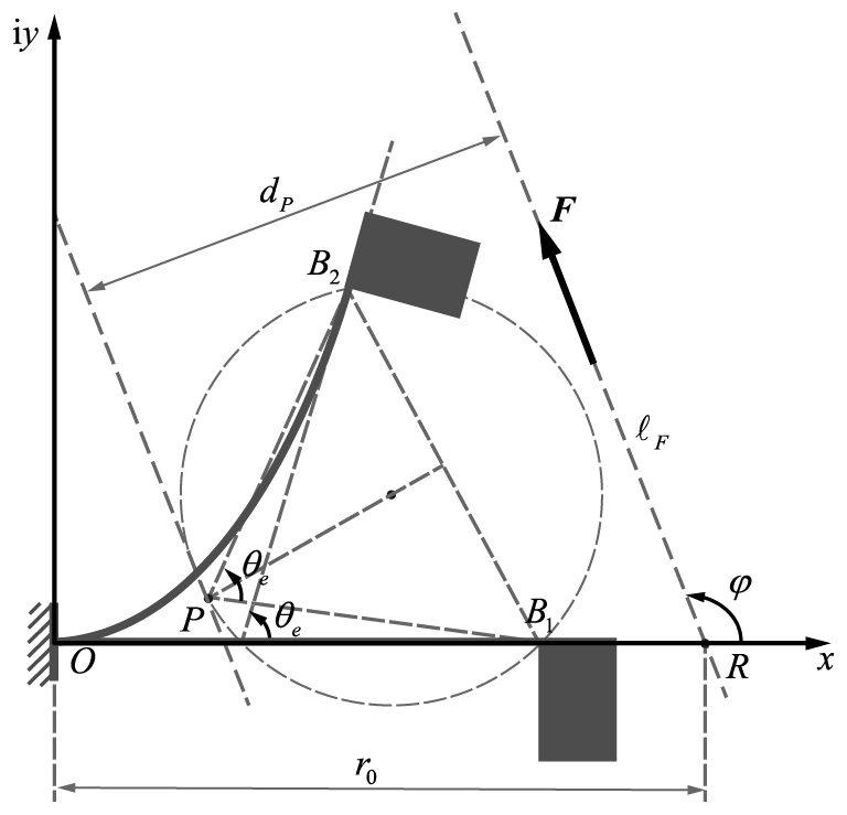
As shown in Fig. 2, the relative positional relationship between the beam's tip positions, B1 and B2, can be described by pole P and its corresponding rotation angle, ϑ. According to the definition of the pole, the position coordinates of pole P and the rotation angle, ϑ, can be calculated by the following formulas:
where represents the tip position of the planar beam in its natural state and represents the tip position of the planar beam carrying the tip loads F and Me. Expanding this formula yields the coordinates of the pole as follows:
Moment MO of the planar beam at frame O is
where . The position of the equivalent load line, ℓF, can be determined by its intersection point with the x axis, R, as follows:
The distance, dP, between pole P and the equivalent load line, ℓF can be calculated by the vector product of the vector RP and equivalent load line, ℓF, as follows:
2.3 The similarity transformation characteristics of planar beams
Pole P of the planar beam completely describes the relative position of the beam's tip. For any planar beam, the rotation direction of the beam's tip, the position of the pole, the distance between the pole and equivalent load line, and the rotation angle of the equivalent load line can be adjusted by the similarity transformation.
2.3.1 Changing the rotation direction through mirror transformation
Planar beams can change the rotation direction by mirroring the load along the x axis. As shown in Fig. 3a, to change the rotation direction of the planar beam, the equivalent force line of the planar beam, , needs to flipped along the x axis. In this scenario, the load angle is , the pole position , and the pole angle .
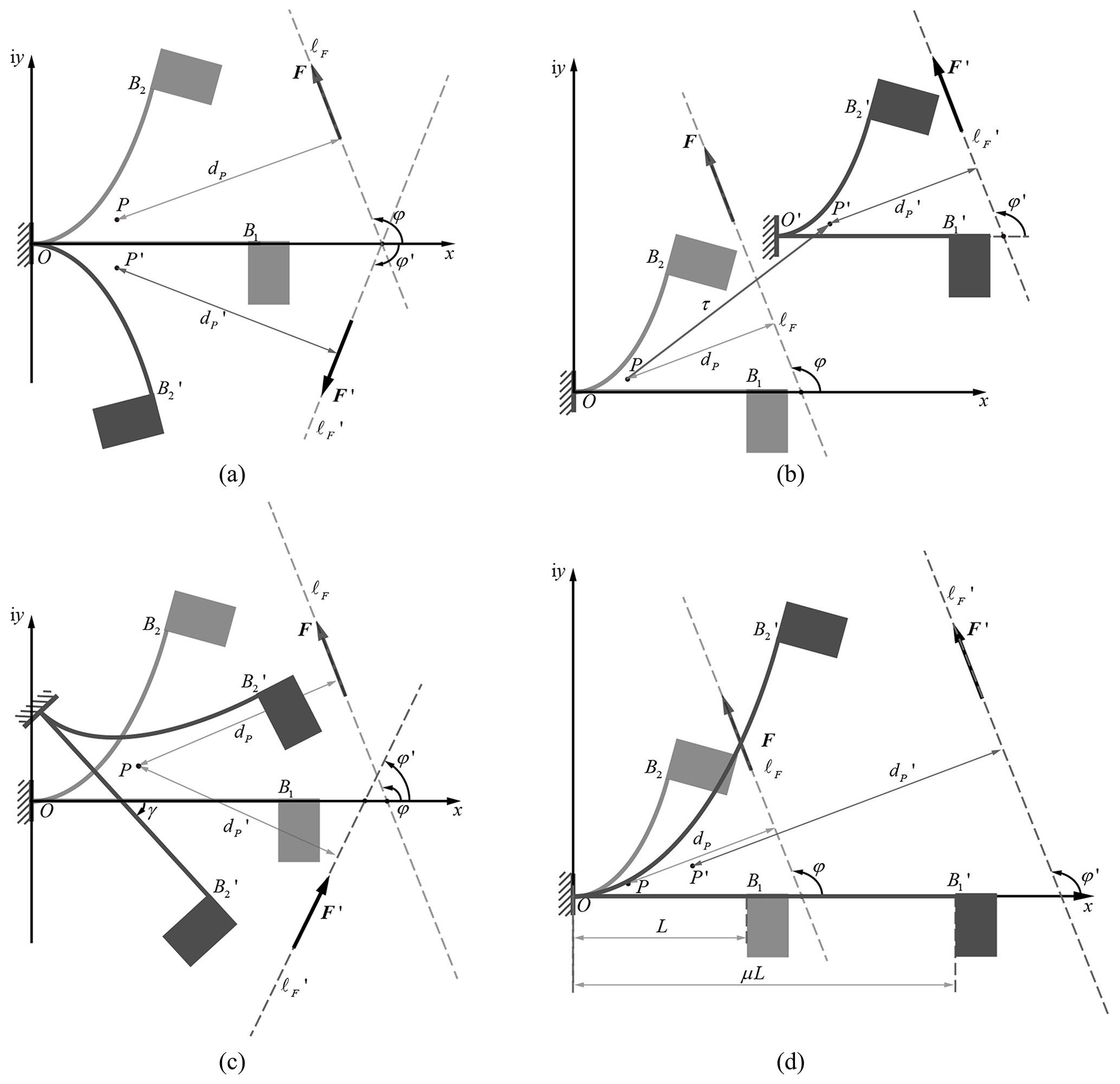
Figure 3The similarity transformation of deformed planar beam: (a) mirror transformation, (b) translation transformation, (c) rotation transformation, and (d) scale transformation.
2.3.2 Changing the pole position through translation transformation
Planar beams can adjust the pole position by translating the frame, O. As shown in Fig. 3b, when pole P of the beam is translated along vector τ, its tip position, ; equivalent force line, ; and frame, O′, also undergo the same translation motion. After translation, the magnitude of the load, F′; the angle of the equivalent force line, φ′; and the distance from pole to the equivalent force line, , all remain unchanged.
2.3.3 Changing the angle of equivalent force line through rotation transformation
Planar beams can adjust the angle of the equivalent force line by rotating the frame O. As shown in Fig. 3c, when the frame O rotates around the pole by an angle, γ, its tip position, , and the equivalent force line, , also undergo the same rotational motion. After rotation, the magnitude of load F′ and the distance from the pole to the equivalent force line remain unchanged. The angle between the equivalent force line and the positive direction of the x axis changes to .
2.3.4 Changing the distance from pole to the equivalent force line through scale transformation
The planar beam can adjust the distance from pole to the equivalent force line by proportionally changing the beam's length, L. As shown in Fig. 3d, when the beam's length is scaled by proportion μ, according to Eqs. (16), (15), and (19), the scaled beam's tip position is , the scaled pole position , and the scaled loads . On this basis, by substituting scaled parameters , , and F′ into Eqs. (20), (21), and (22), it can be concluded that the scaled distance from the pole to equivalent force line is .
Through the analysis of the deformation behavior of the planar beam, the load required for achieving a given beam's tip rotation is determined. The relative positional relationship between the two positions of the beam's tip is described using the pole. Through the pole similarity transformation, the pole position and the equivalent force line of the beam can be flexibly adjusted within the motion plane. In order to ensure that the rigid components of the compliant mechanism are in a stable state at specified positions, it is necessary to arrange the planar beams of the compliant mechanism into suitable positions. This paper utilizes the characteristics of the similarity transformation to adjust the pole position of the planar beams, ultimately establishing a synthesis method for the rigid-body guidance problem of compliant bistable mechanisms.
3.1 The motion task and structural characteristic of the designed compliant mechanism
Figure 4 shows two stable positions of the bistable mechanism that needs to be designed in this paper, which consists of three planar beams and two rigid components. In the natural state, the flexible beams are located at , , and , respectively. The three beams are connected to the rigid components and . , , and represent the deformation states of the three planar beams when and are the rigid components at the second stable position. In this paper, the two given positions of first rigid component are and , while the two given positions of the second rigid component are and , respectively. The motion task of the rigid guidance problem can be described by the poles. As shown in Fig. 5, the pole of first component, Pa, can be calculated by
while the pole of second component, Pb, can be calculated by


3.2 Determination of structural parameters of the designed compliant mechanism
3.2.1 The poles of planar beams in the designed compliant mechanism
In the compliant mechanism, two planar beams, and , are connected to the frame on one tip and to the rigid components on the other tip, so their poles should be consistent with the poles of the motion task, Pa(ϑa) and Pb(ϑb). The two tips of the third planar beam, , are connected to two rigid components, respectively; thus, there are two poles, Pc and , that correspond to two stable equilibrium positions. As shown in Fig. 6, pole can be viewed as the result of rotating Pc around Pa by ϑa or as the result of rotating Pc around Pb by ϑb. Therefore, Pc and are symmetric in relation to the line PaPb. When we know the poles of two rigid components, we connect the poles Pa and Pb, rotate PaPb around Pa by ϑa, and then rotate PaPb around Pb by ϑb. The intersection of the two lines is the first pole of the third beam, Pc. Similarly, when PaPb is rotated around Pa and Pb by −ϑa and −ϑb, respectively, the intersection is the second pole of the third beam . The pole of third beam represents the relative angle between two rigid components, which is known from the characteristic of the polar triangle, i.e., the rotation angle .

Figure 6The pole of the three planar beams of the compliant mechanism in the motion generation problem.
3.2.2 The structural parameters of the designed compliant mechanism
After determining the poles of each planar beam, it is necessary to determine the dimensional parameters and installation positions of the planar beams in the compliant mechanism. The process is as follows:
- 1.
Determination of the load balance line. The first stable position of the bistable compliant mechanism is the natural state of the mechanism, in which the planar beams are not subjected to external forces. When the compliant mechanism is in the second stable position, the equilibrium of the mechanism is achieved through the interaction forces between the beams. Therefore, in order to ensure that the compliant mechanism maintains balance in the second stable position, the equivalent instances of the force line of the three compliant beams, , need to coincide, and the coinciding position is the load balance line, ℓB.
As shown in Fig. 7, due to the opposite rotation directions of the two planar beams connected to the frame, the directions of their loads, Fa and Fb, are also opposite. In order to ensure the balance of forces on the rigid components, load Fc on the third beam has the same direction as Fa. The position and angle of the load balance line can be arbitrarily given, but it needs to ensure that the load balance line, ℓB, passes through two edges, and , of the pole triangle . After the load balance line is selected, the load directions of each beam in the xOy coordinate system are already determined – that is, the directions of Fa and Fc are , and the direction of Fb is . Based on this, the distances , , and between the poles of planar beams and the load balance line are also determined.
- 2.
The initial solution of planar beams. The rotation angle of the beam's tip, , is determined by the pole angle of each beam. To avoid negative curvature, a mirror transformation is required for the planar beam with negative pole rotation. Taking Fig. 6 as an example, beams b and c need to be reversed using a mirror transformation. The rotation angle of the planar beams can be calculated by
The elastic modulus, E, of the planar beam needs to be determined based on the selected material, and the section height, ; section width, ; beam length, ; load ratio, ; and load angle, , of each planar beam can be arbitrarily chosen. After parameter selection, as shown in Fig. 8, the position of the pole, , the load magnitude, , and the distance from the equivalent force line to the pole of the planar beam, , can be calculated according to the procedures in Sect. 2.1 and 2.2. The calculated result is the initial solution of the planar beam.
- 3.
The similarity transformation of planar beam. To meet the requirements of the motion task, pole and the equivalent force line of the planar beams, , need to be transformed to the suitable positions (Pk and ℓB) in the compliant mechanism. For each planar beam, four steps of the pole similarity transformation are required.
- a.
Translation transformation. Pole of the planar beam k is moved to the origin, and the translation vector , where .
- b.
Scale transformation. In order to ensure that , planar beam k is subjected to a scale transformation with a scaling factor, , where . After the scaling transformation, the load magnitude of the planar beam also changes to .
- c.
Rotation transformation. In order to make parallel to ℓB, planar beam k needs to undergo a rotation transformation with an angle of , where .
- d.
Translation transformation. The rotated planar beam, k, needs to be translated back to the pole of the compliant mechanism, and the translation vector is , where .
- a.
- 4.
Determination of the beams' width. After the similarity transformation, the load position and motion of the planar beam already satisfy the requirements of the compliant bistable mechanism. In order to ensure that the static equilibrium condition is satisfied at the second stable position, it is necessary to adjust the width of the planar beam bk to unify the load magnitude, Fk. According to the scaled load, , of each planar beam k, the equilibrium load at the second stable position of the compliant mechanism, Fm, is selected. According to Eq. (15), the tip load of the planar beam is proportional to the inertia moment, I. For the rectangular cross section, the inertia moment, I, is proportional to the width of the cross section. Therefore, the cross-section width of each planar beam k is adjusted in proportion to the load magnitude, , and equilibrium load Fm – that is, , where .

3.3 The synthesis process of the bistable compliant mechanism
Based on the pole similarity transformation, the synthesis process of the bistable compliant mechanism is shown in Fig. 9. First, the poles and corresponding pole angles of the rigid components and planar beams in the compliant mechanism are determined based on the given positions of the motion task. Second, the load balance line and the magnitude of the equilibrium load for the compliant mechanism are selected. Then, the initial solution of the planar beams based on the geometric and mechanical features is obtained, and so are the compliant mechanism solution that satisfies the motion task requirements and static equilibrium conditions through similarity transformation. Finally, output the relevant parameters of the planar beams and rigid components in the compliant mechanism for the specific design of the compliant mechanism. After defining the input and output of the program, this synthesis process can be automatically completed using MATLAB software.

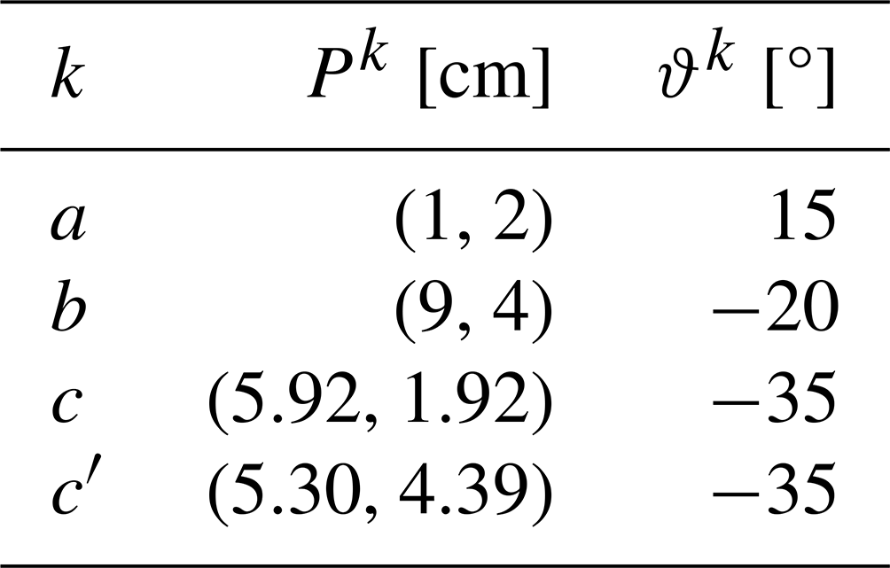
This section takes the planar two-position rigid-body guidance mechanism as an example and designs a bistable compliant mechanism based on the proposed synthesis process. The guidance positions of the rigid components are , and , . Table 1 shows the motion task parameters.

According to the proposed synthesis process, the geometric features of the motion task and the compliant mechanism are first extracted. Poles Pa and Pb are determined according to Eqs. (23) and (24). Poles Pc and are obtained by rotation and pole angle of . The specific results are shown in Table 2.
Table 2Geometric features of the motion task and the compliant mechanism.
The position of the load balance line is selected according to the position of the poles. The load balance line passes through points (0.5 cm, 2.5 cm) and (8.5 cm, 4.5 cm), and ϕ = 194.04°. The magnitude of equilibrium load is Fm = 0.5 N. The distance from poles Pa, Pb, and to the load balance line, ℓB, is determined to be = 0.606 cm, = 0.606 cm, and = 0.666 cm, respectively. The material selected for the planar beams is 65Mn spring steel, with an elastic modulus of E = 210 000 MPa.
The initial parameters of the planar beams need to be selected, including the initial length, = 1 cm; initial width, = 0.1 cm; and initial height, = 0.005 cm. The load ratio, , and angle of equivalent force line, , are shown in Table 3. Based on these parameters, the initial solutions of the planar beams are determined. As shown in Table 4, the similarity transformation parameters of the three beams are calculated according to Sect. 3.2.2. After transforming the planar beams to the corresponding pole positions, all parameters of the compliant mechanism can be determined. The specific result can be found in Table 5 and Fig. 10.
Table 3Parameters for the initial solution of compliant mechanism.

Table 4Similarity transformation parameters of compliant mechanism.
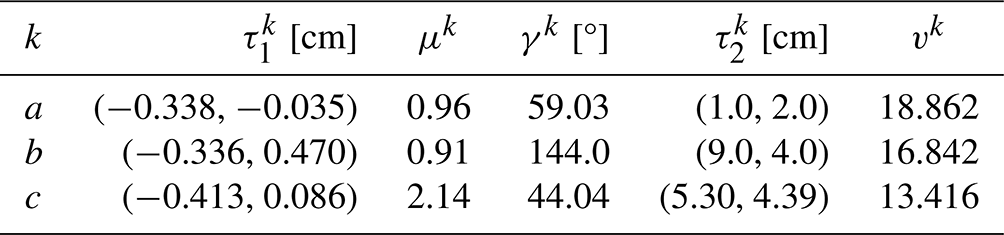
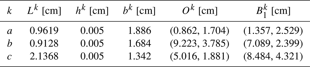
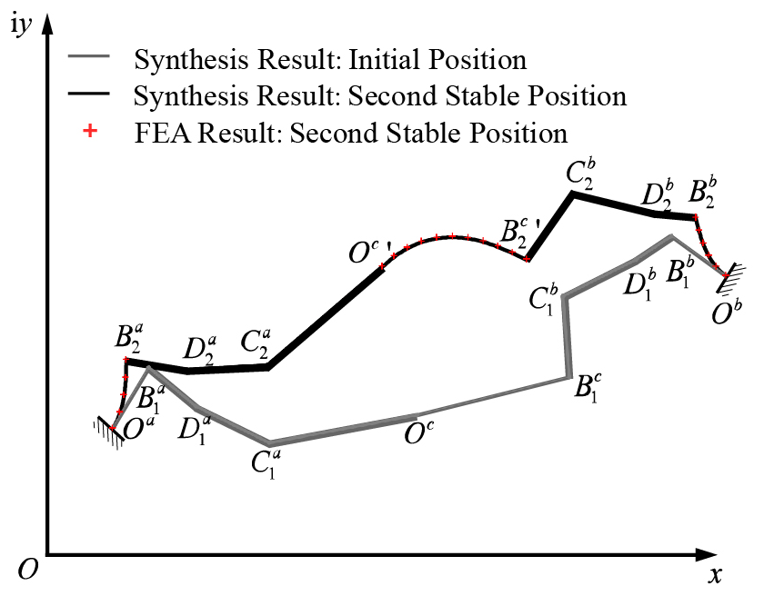
Figure 10The synthesis results of compliant bistable mechanism and their comparison with finite-element analysis (FEA).
The synthesis process of bistable compliant mechanism for the rigid-body guidance problem is completed. The designed compliant mechanism is modeled in finite-element analysis (FEA) software to verify the motion accuracy and bistable characteristics. As shown in Fig. 11a, the models of planar beams are imported into the FEA software and establish rigid constraints between the beams to simulate the connection of rigid components in the compliant mechanism. Two reference points are established at and , and they are fixed to the tips of slender beams a and b. The rotation constraint is applied at the reference points of , and the first rigid component is driven to rotate counterclockwise by Δβa = 35°, indicating that the mechanism will reach and surpass the second stable position. The deformation of the mechanism at the initial position and the second stable position is shown in Fig. 11b. The strain energy of the mechanism and the second rigid component's motion during the movement are shown in Fig. 12. It can be observed that in the simulation, the strain energy of the mechanism reaches a local minimum when the rotation angle of the first rigid component reaches 30°. At this point, the rotation angle of the second rigid component is −40°, and the coordinates of reference points and are (1.87 cm, 2.50 cm) and (8.23 cm, 4.64 cm), respectively, indicating that the designed mechanism meets the requirement of stable positions in the motion task. The beam's shape of the second stable position in the simulation is shown in Fig. 10.
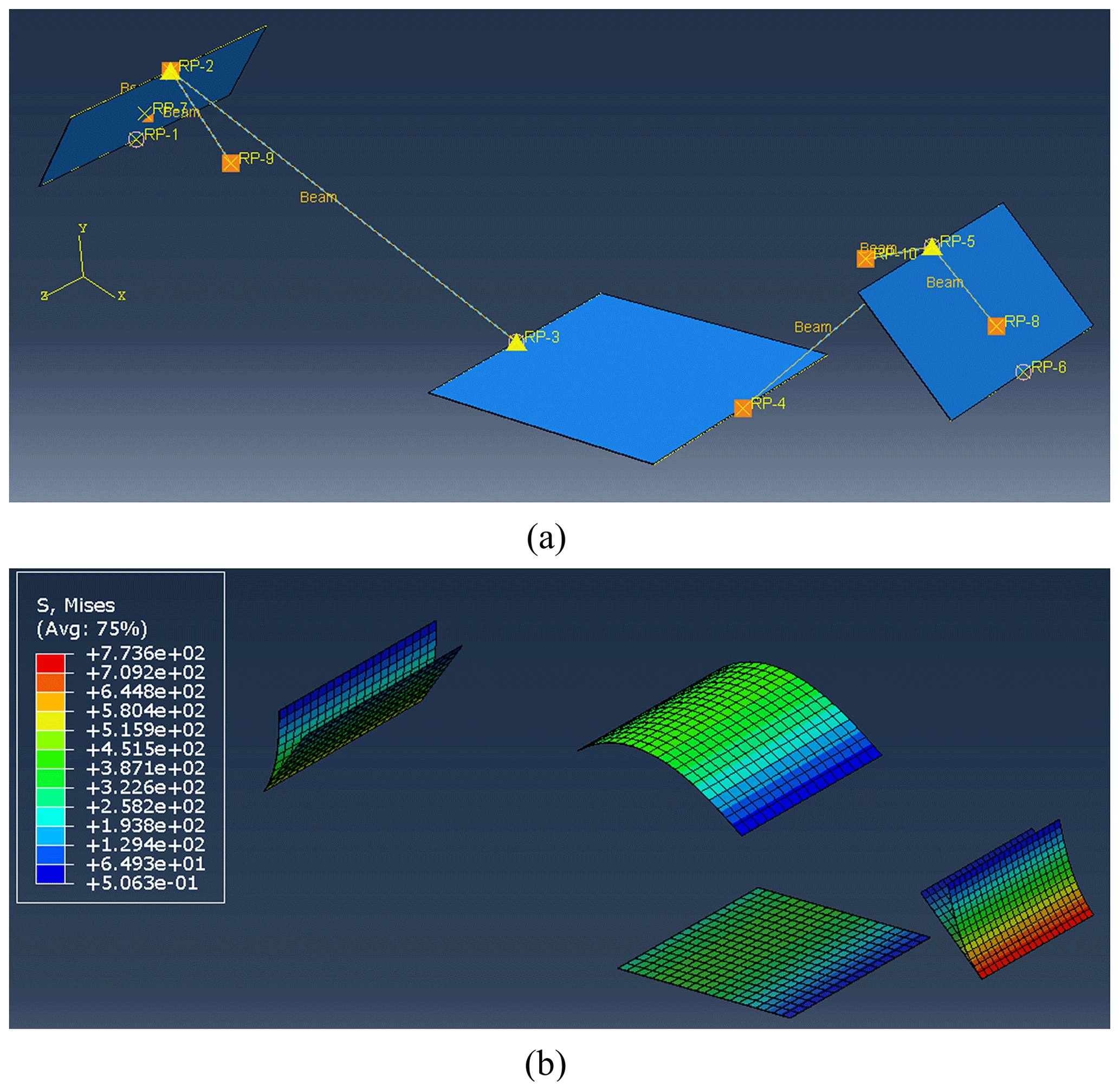

Figure 12The FEA results regarding the strain energy of the compliant mechanism and second rigid component's motion.
The prototype is manufactured according to the synthesis results. As shown in Fig. 13, the frame and rigid components in the mechanism are manufactured through 3D printing. The planar beams are made of spring steel (65Mn). The planar beams and rigid components are securely fastened together using bolted connections. Three yellow markers are added to the frame and rigid components using 3D printing. The second stable position of the prototype is shown in Fig. 13. The red markers in the figure represent the results from the finite-element analysis at the second stable position, and it can be observed that the deformation of the planar beams in the prototype is consistent with the simulation results.
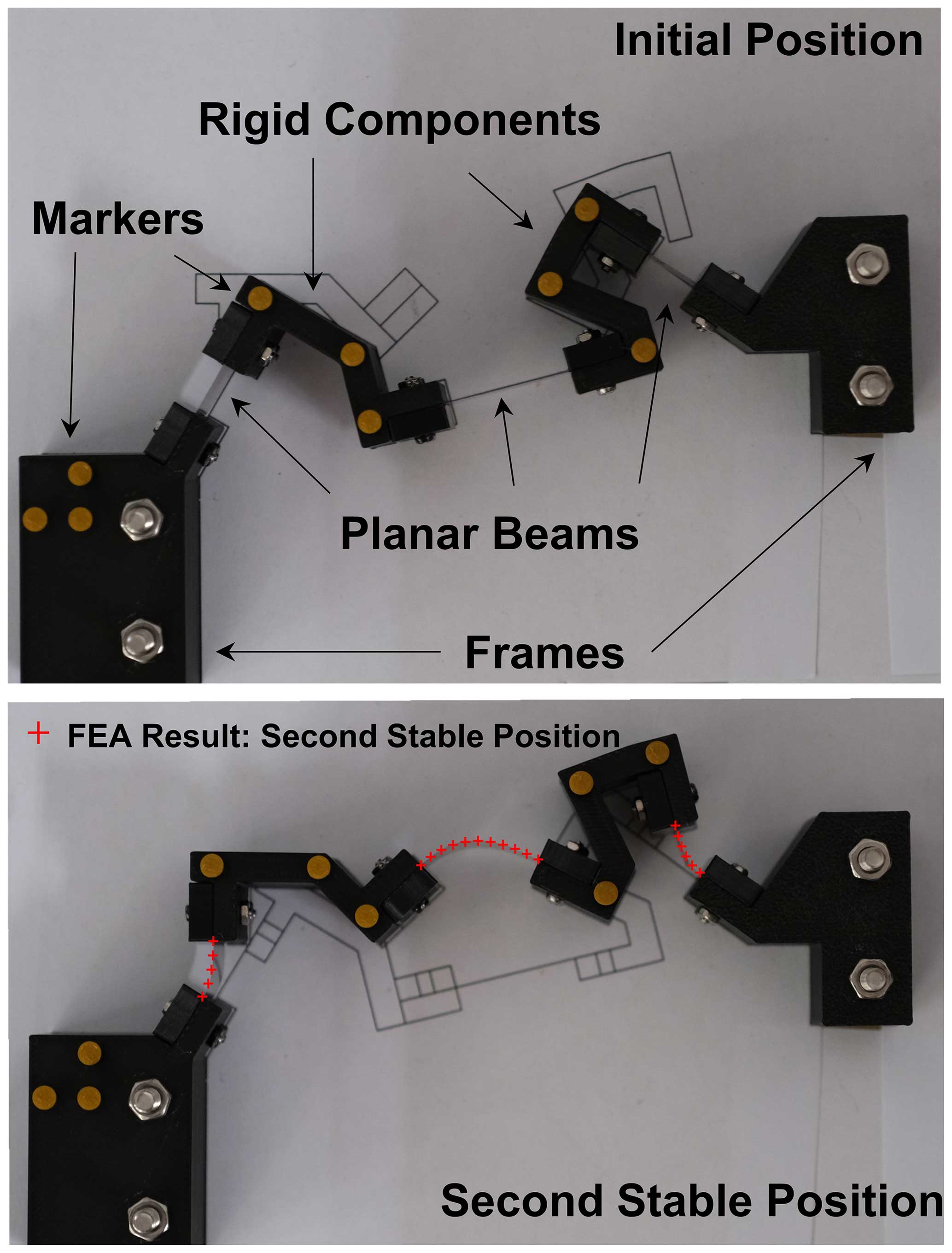
Figure 13The prototype and the comparison of the beams' shape at the second stable position with FEA results.
We utilize monocular ranging algorithm to calculate the stable position of the rigid components in the prototype. As shown in Fig. 14, image-processing techniques are employed to identify the markers on the frame and rigid components. The three markers on the frame are used to determine the origin and orientation of the coordinate system for the prototype. The positions of the markers on the rigid components can be calculated through coordinate transformation. The pole angles and the location of the poles are calculated by the markers. Any two markers on the same rigid component can form a directed line segment. By utilizing the positional relationship of directed line segments between two stable positions, a pole and its corresponding pole angle can be determined. The results are presented in Table 6. The maximum error for the location of the pole is 3.82 %, and the maximum error for the pole angle is 4.92 %.
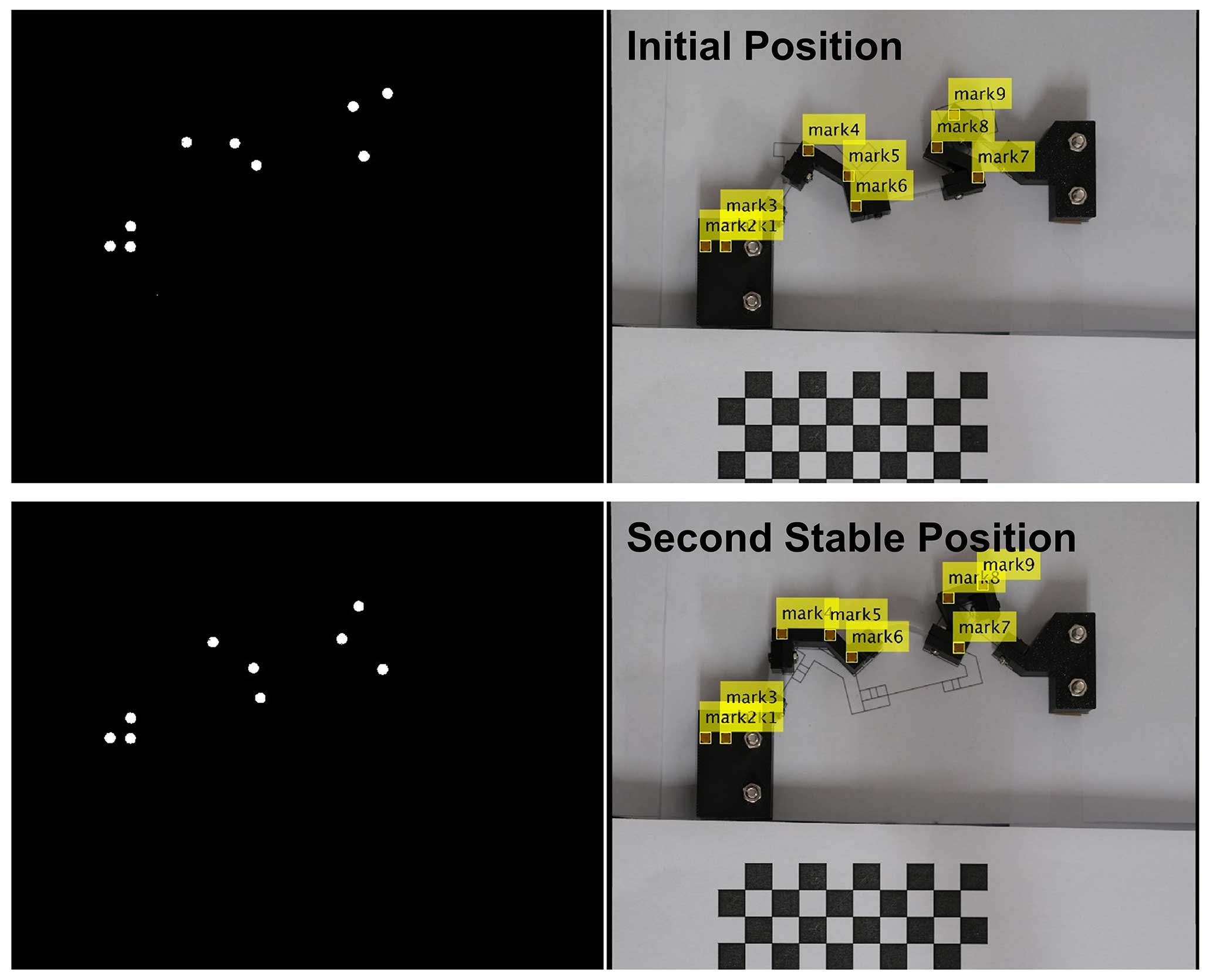
Table 6The pole angles and location of poles of the prototype.

Due to the self-holding characteristic of the bistable mechanism, the driving force or torque of the mechanism has significant features. There are three states with zero driving force between the two stable positions, which corresponds to the positions of minimum and maximum strain energy. To measure the driving torque of the prototype, an experimental platform is set up as shown in Fig. 15. The first rigid component is made to rotate using a servo motor in position mode. The driving torque is recorded using a torque sensor. The experiment is repeated three times, and the comparison between the experimental results and the simulation is shown in Fig. 16. It can be seen that the results of the three experiments show good consistency. Throughout the motion process, the driving torque has three intersections with the x axis, verifying the bistable characteristic of the mechanism. The first intersection is located at the initial position with a driving angle of Δβa = 0°, and the third intersection is located at the second stable position with a driving angle of approximately Δβa = 30°, which is consistent with the design goal. The second intersection is located at a driving angle of Δβa = 26°, which is greater than the simulated result of 25°. This is mainly caused by manufacturing and assembly errors in the prototype.


Poles are a geometric tool that can accurately describe multiple planar positions, and they can reveal the relationship between guidance mechanisms and given design tasks. Based on the similarity transformation of poles, this paper proposes a novel synthesis method for compliant bistable mechanisms. The synthesis example and results of simulation and prototype experiments have demonstrated the effectiveness of the proposed method. Regarding the proposed design method, future research can focus on the following two aspects:
- 1.
Study on the energy and mechanical characteristics of the intermediate states in bistable mechanisms. The proposed method can design the stable positions of the mechanism based on the motion task. However, the maximum strain energy and maximum driving force between the two stable positions of the mechanism also have important research value. How to incorporate the calculations of these intermediate characteristics into the overall process of mechanism synthesis will be a key issue for future research.
- 2.
Research on integrated manufacturing methods for mechanisms. One important advantage of compliant mechanisms is their ability to be manufactured in an integrated manner, eliminating the assembly process. In the proposed method, the planar beams have different widths, which requires us to manufacture and assemble the components separately. The assembly process not only limits the size of the prototype but also introduces significant assembly errors. Exploring miniaturized integrated manufacturing methods is also one of the important research topics for future studies.
This paper proposes a novel geometrical approach to bistable compliant mechanism synthesis based on the similarity transformation of poles. The study demonstrates the feasibility of decoupling the kinematic design and static analysis processes in the synthesis of bistable compliant mechanisms. At the method level, a general synthesis process for bistable compliant mechanisms is provided, simplifying the iterative process in the design of compliant mechanisms and offering an efficient synthesis tool for general compliant bistable mechanisms. In addition, this study illustrates the synthesis approach with an example, and a prototype was made.
All the code and data used in this paper can be obtained from the corresponding author upon request.
JJ and SL proposed the methodology. HW took part in the discussion of the paper.
The contact author has declared that none of the authors has any competing interests.
Publisher’s note: Copernicus Publications remains neutral with regard to jurisdictional claims made in the text, published maps, institutional affiliations, or any other geographical representation in this paper. While Copernicus Publications makes every effort to include appropriate place names, the final responsibility lies with the authors.
The authors would like to thank anonymous reviewers for their valuable comments and suggestions that enabled them to revise the paper.
This research has been supported by the Natural Science Foundation of Fujian Province (grant no. 2022J05246).
This paper was edited by Engin Tanık and reviewed by two anonymous referees.
Awtar, S., Slocum, A. H., and Sevincer, E.: Characteristics of Beam-Based Flexure Modules, J. Mech. Design, 129, 625–639, 2006. a
Chase Jr., R. P., Todd, R. H., Howell, L. L., and Magleby, S. P.: A 3-D chain algorithm with pseudo-rigid-body model elements, Mech. Based Des. Struc., 39, 142–156, 2011. a
Chen, G., Ma, F., Bai, R., Magleby, S. P., and Howell, L. L.: A Framework for Energy-Based Kinetostatic Modeling of Compliant Mechanisms, in: ASME 2017 International Design Engineering Technical Conferences and Computers and Information in Engineering Conference, Cleveland, Ohio, USA, 6–9 August 2017, 5A, p. V05AT08A021, https://doi.org/10.1115/DETC2017-68205, 2017. a
Chen, J.-q., Hao, Y.-x., and Zhang, W.: STATIC and SNAP-through Behaviors of trapezoidal BI-stable Laminates, in: 2020 15th Symposium on Piezoelectrcity, Acoustic Waves and Device Applications (SPAWDA), Zhengzhou, Henan Province, China, 16–19 April 2021, IEEE, 650–658, https://doi.org/10.1109/SPAWDA51471.2021.9445512, 2021. a
Chen, Q., Zhang, X., Zhang, H., Zhu, B., and Chen, B.: Topology optimization of bistable mechanisms with maximized differences between switching forces in forward and backward direction, Mech. Mach. Theory, 139, 131–143, 2019. a
Chi, I. T., Tien Hoang, N., Chang, P.-L., Ngoc Dang Khoa, T., and Wang, D.-A.: Design of a bistable mechanism with B-spline profiled beam for versatile switching forces, Sensor. Actuat. A-Phys., 294, 173–184, https://doi.org/10.1016/j.sna.2019.05.028, 2019. a
Dado, M. H.: Variable parametric pseudo-rigid-body model for large-deflection beams with end loads, Int. J. Nonlin. Mech., 36, 1123–1133, 2001. a
Haddab, Y., Aiche, G., Hussein, H., Salem, M. B., Lutz, P., Rubbert, L., and Renaud, P.: Mechanical Bistable Structures for Microrobotics and Mesorobotics from Microfabrication to Additive Manufacturing, in: 2018 International Conference on Manipulation, Automation and Robotics at Small Scales (MARSS), Nagoya, Japan, 4–8 July 2018, IEEE, 1–6, https://doi.org/10.1109/MARSS.2018.8481186, 2018. a
Han, Q., Jin, K., Chen, G., and Shao, X.: A novel fully compliant tensural-compresural bistable mechanism, Sensor. Actuat. A-Phys., 268, 72–82, 2017. a
Holst, G. L., Teichert, G. H., and Jensen, B. D.: Modeling and experiments of buckling modes and deflection of fixed-guided beams in compliant mechanisms, J. Mech. Design, 133, 051002, https://doi.org/10.1115/1.4003922, 2011. a
Howell, L. L. and Midha, A.: A Method for the Design of Compliant Mechanisms With Small-Length Flexural Pivots, J. Mech. Design, 116, 280–290, https://doi.org/10.1115/1.2919359, 1994. a
Howell, L. L., Magleby, S. P., and Olsen, B. M.: Handbook of Compliant Mechanisms, John Wiley & Sons, ISBN: 9781119953456, https://doi.org/10.1002/9781118516485, 2013. a
Huang, S.-W., Lin, F.-C., and Yang, Y.-J.: A novel single-actuator bistable microdevice with a moment-driven mechanism, Sensor. Actuat. A-Phys., 310, 111934, https://doi.org/10.1016/j.sna.2020.111934, 2020. a
Hussein, H., Le Moal, P., Younes, R., Bourbon, G., Haddab, Y., and Lutz, P.: On the design of a preshaped curved beam bistable mechanism, Mech. Mach. Theory, 131, 204–217, https://doi.org/10.1016/j.mechmachtheory.2018.09.024, 2019. a
Hussein, H., Khan, F., and Younis, M. I.: A symmetrical bistable mechanism from combination of pre-shaped microbeams, Sensor. Actuat. A-Phys., 306, 111961, https://doi.org/10.1016/j.sna.2020.111961, 2020. a
Jiang, J., Lin, S., Wang, H., and Modler, N.: Modeling Method for Static Large Deflection Problem of Curved Planar Beams in Compliant Mechanisms Based on a Novel Governing Equation, J. Mech. Robot., 16, 031014, https://doi.org/10.1115/1.4062916, 2023. a
Jiang, J., Lin, S., Wang, H., and Modler, N.: The synthesis method of series-based bistable compliant mechanisms for rigid-body guidance problem based on geometrical similarity transformation of pole maps, J. Mech. Design, 146, 103301, https://doi.org/10.1115/1.4065023, 2024. a
Jin, M., Zhu, B., Mo, J., Yang, Z., Zhang, X., and Howell, L. L.: A CPRBM-based method for large-deflection analysis of contact-aided compliant mechanisms considering beam-to-beam contacts, Mech. Mach. Theory, 145, 103700, https://doi.org/10.1016/j.mechmachtheory.2019.103700, 2020. a
Kalpathy Venkiteswaran, V. and Su, H.-J.: Pseudo-Rigid-Body Models of Initially-Curved and Straight Beams for Designing Compliant Mechanisms, in: Proceedings of the ASME 2017 International Design Engineering Technical Conferences and Computers and Information in Engineering Conference, Cleveland, Ohio, USA, 6–9 August 2017, ASME, 5A, v05AT08A006, https://doi.org/10.1115/DETC2017-67431, 2017. a
Kimball, C. and Tsai, L.-W.: Modeling of Flexural Beams Subjected to Arbitrary End Loads, J. Mech. Design, 124, 223–235, 2002. a
Lin, S., Zhang, Y., Wang, H., Jiang, J., and Modler, N.: Geometric synthesis method of compliant mechanism based on similarity transformation of pole maps, Mech. Sci., 12, 375–391, https://doi.org/10.5194/ms-12-375-2021, 2021. a
Lobontiu, N.: Compliant mechanisms: design of flexure hinges, CRC Press, https://doi.org/10.1201/9781420040272, ISBN: 9780429121654, 2002. a
Ma, F. and Chen, G.: Modeling Large Planar Deflections of Flexible Beams in Compliant Mechanisms Using Chained Beam-Constraint-Modell, J. Mec. Robot., 8, 021018, https://doi.org/10.1115/1.4031028, 2015. a
McCarthy, J. M. and Soh, G. S.: Geometric design of linkages, Vol. 11, Springer Science & Business Media, https://doi.org/10.1007/978-1-4419-7892-9, ISBN: 978-1-4419-7891-2, 2010. a
Midha, A., Howell, L. L., and Norton, T. W.: Limit positions of compliant mechanisms using the pseudo-rigid-body model concept, Mech. Mach. Theory, 35, 99–115, 2000. a
Nathan, D. and Howell, L.: A self-retracting fully compliant bistable micromechanism, J. Microelectromech. S., 12, 273–280, 2003. a
Parkinson, M. B., Jensen, B. D., and Roach, G. M.: Optimization-Based Design of a Fully-Compliant Bistable Micromechanism, in: Proceedings of the ASME 2000 International Design Engineering Technical Conferences and Computers and Information in Engineering Conference, 26th Biennial Mechanisms and Robotics Conference. Baltimore, Maryland, USA, 10–13 September 2000, ASME, 7A, 635–641, https://doi.org/10.1115/DETC2000/MECH-14119, 2000. a
Qiu, J., Lang, J., and Slocum, A.: A curved-beam bistable mechanism, J. Microelectromech. S., 13, 137–146, https://doi.org/10.1109/JMEMS.2004.825308, 2004. a
Sargent, B., Butler, J., Seymour, K., Bailey, D., Jensen, B., Magleby, S., and Howell, L.: An Origami-Based Medical Support System to Mitigate Flexible Shaft Buckling, J. Mech. Robot., 12, 041005, https://doi.org/10.1115/1.4045846, 2020. a
Saxena, A. and Kramer, S. N.: A Simple and Accurate Method for Determining Large Deflections in Compliant Mechanisms Subjected to End Forces and Moments, J. Mech. Design, 120, 392–400, 1998. a
Shoup, T. E. and McLarnan, C. W.: On the Use of the Undulating Elastica for the Analysis of Flexible Link Mechanisms, J. Eng. Ind., 93, 263–267, 1971. a
Sönmez, U. and Tutum, C. C.: A Compliant Bistable Mechanism Design Incorporating Elastica Buckling Beam Theory and Pseudo-Rigid-Body Model, J. Mech. Design, 130, 042304, https://doi.org/10.1115/1.2839009, 2008. a
Su, H.-J.: A Pseudo-Rigid-Body 3R Model for Determining Large Deflection of Cantilever Beams Subject to Tip Loads, J. Mech. Robot., 1, 021008, https://doi.org/10.1115/1.3046148, 2009. a
Todd, B., Jensen, B. D., Schultz, S. M., and Hawkins, A. R.: Design and testing of a thin-flexure bistable mechanism suitable for stamping from metal sheets, J. Mech. Design, 132, 071011, https://doi.org/10.1115/1.4001876, 2010. a
Tran, N. D. K. and Wang, D.-A.: Design of a crab-like bistable mechanism for nearly equal switching forces in forward and backward directions, Mech. Mach. Theory, 115, 114–129, 2017. a
Turkkan, O. A. and Su, H.-J.: A general and efficient multiple segment method for kinetostatic analysis of planar compliant mechanisms, Mech. Mach. Theory, 112, 205–217, https://doi.org/10.1016/j.mechmachtheory.2017.02.010, 2017. a
Turkkan, O. A., Venkiteswaran, V. K., and Su, H.-J.: Rapid conceptual design and analysis of spatial flexure mechanisms, Mech. Mach. Theory, 121, 650–668, https://doi.org/10.1016/j.mechmachtheory.2017.11.025, 2018. a
Wang, P. and Xu, Q.: Design of a flexure-based constant-force XY precision positioning stage, Mech. Mach. Theory, 108, 1–13, https://doi.org/10.1016/j.mechmachtheory.2016.10.007, 2017. a
Wilcox, D. L. and Howell, L. L.: Double-tensural bistable mechanisms (DTBM) with on-chip actuation and spring-like post-bistable behavior, in: ASME 2005 International Design Engineering Technical Conferences and Computers and Information in Engineering Conference, Long Beach, California, USA, 24–28 September 2005, American Society of Mechanical Engineers, https://doi.org/10.1115/DETC2005-84697, ISBN: 0-7918-4744-6, 2005. a
Yu, Y.-Q. and Zhu, S.-K.: 5R pseudo-rigid-body model for inflection beams in compliant mechanisms, Mech. Mach. Theory, 116, 501–512, 2017. a
Yu, Y.-Q., Feng, Z.-L., and Xu, Q.-P.: A pseudo-rigid-body 2R model of flexural beam in compliant mechanisms, Mech. Mach. Theory, 55, 18–33, 2012. a
Zhang, A. and Chen, G.: A Comprehensive Elliptic Integral Solution to the Large Deflection Problems of Thin Beams in Compliant Mechanisms, J. Mech. Robot., 5, 021006, https://doi.org/10.1115/1.4023558, 2013. a
Zhao, J., Jia, J., He, X., and Wang, H.: Post-buckling and Snap-Through Behavior of Inclined Slender Beams, J. Appl. Mech., 75, 041020, https://doi.org/10.1115/1.2870953, 2008. a
Zhu, S.-K. and Yu, Y.-Q.: Pseudo-Rigid-Body Model for the Flexural Beam With an Inflection Point in Compliant Mechanisms, J. Mech. Robot., 9, 031005, https://doi.org/10.1115/1.4035986, 2017. a