the Creative Commons Attribution 4.0 License.
the Creative Commons Attribution 4.0 License.
 | 13 Aug 2024
Simulated vibration characterization of the aero-turbine engine vibration isolation system under broadband random excitation
Huawen Peng
Bo Zou
Jingyun Yang
Rong Fu
Xingwu Ding
Da Zhang
Guangfu Bin
Aiming at the actual demand of wide-frequency vibration isolation and low-frequency shock resistance of the vibration isolation system for complex external excitation of the aircraft turboprop engine. The dynamic performance of a certain type of turbo-propeller engine vibration isolation system at a 1.5–2000 Hz vibration frequency is investigated by combining simulations and experimental research. Firstly, an equivalent test device for the vibration isolation system of an aircraft turboprop engine is designed, and the reliability of the device structure is verified by finite-element analysis. Then, based on the trial model, sweep frequency vibration tests in three vibration directions are carried out, and the vibration isolation performance of the vibration isolation system under random excitation is analyzed. Finally, the transfer functions of the vibration isolation system in three vibration directions are calculated, and the vibration amplification of the vibration isolation system subjected to low-frequency resonance is analyzed. It provides a test basis and idea for the optimization design of the aero-engine vibration isolation system.
- Article
(4776 KB) - Full-text XML
- BibTeX
- EndNote


The aircraft turboprop engine as an efficient and reliable power source provides strong thrust and low fuel consumption for shipboard aircraft, enabling them to carry out a wide range of complex tasks, such as early warning, transport and combat in the maritime environment (Kirmizi et al., 2024; Zheng et al., 2024; Lee et al., 2023; W. Chen et al., 2024). The vibration of aero-engine structures has been widely studied due to the complex operating environment (Ma et al., 2024; Yang et al., 2023b; T. Yang et al., 2022; Bin et al., 2023; P. Yang et al., 2022; Wang et al., 2023; Zhao et al., 2022; Lu et al., 2023). Shipboard turboprop engines and aircraft nacelles are usually installed between the vibration isolator to not only isolate and reduce the strong vibration and noise generated by the engine on the aircraft, but also reduce the landing, catapult take-off and other conditions of the large overload transferred to the engine shock load to ensure the safe and stable operation of the engine. Therefore, the design and performance of the vibration isolation system as an important part of the aircraft turboprop engine is of great significance in reducing vibration transmission, extending engine life and improving ride comfort (Afonso et al., 2023; Tahan et al., 2017; Filippone et al., 2014).
A large number of researchers have carried out research on the design of aero-engine vibration isolators. Kwon et al. (2020) designed a blade-type passive vibration isolator to provide high damping and fatigue durability of the isolator under harsh launch loads. Somanath et al. (2023) studied the vibration isolator under a dynamic load in the preloaded state and proposed an improved mathematical model of elastomeric materials to predict the random vibration response of typical vibration isolators. Kocak and Yilmaz (2023) designed a lever-type passive vibration isolator, which produces an anti-resonance frequency caused by inertial coupling by increasing the effective mass of the lever to reduce the adverse effects of low-frequency vibration. Oh et al. (2013) designed a passive launch and on-orbit vibration isolation system for spaceborne cryogenic coolers to attenuate the vibration of compressors under on-orbit conditions. Wang et al. (2022) studied a lever-type high-static and low-dynamic stiffness isolator, which uses nonlinear stiffness to construct quasi-zero stiffness characteristics. Leng et al. (2022) proposed a semi-active X-shaped vibration isolation system with magnetorheological elastomers, which can be applied to variable stiffness vibration isolation in broadband and low-frequency range. G. Yan et al. (2024) proposed a novel bionic multi-joint vibration isolator using two rigid rods to simulate the femur and tibia, which has flexible and adjustable high-static and low-dynamic stiffness characteristics. Fu et al. (2019) proposed an adaptive fuzzy controller design method for the magnetorheological elastomer vibration isolation system with time-varying sinusoidal excitation. Lin et al. (2023) proposed a new type of vibration isolator based on the anisotropic magnetorheological elastomer embedded in radial iron chain, whose stiffness and damping characteristics are positively correlated with the applied current. These studies provide the theoretical basis and research ideas for the design of aero-engine isolators.
Vibration environment tests are widely used to evaluate the performance of structures (Yang et al., 2024; Liang et al., 2024; Kan and Xing, 2022). To verify the performance of the isolator, in the experimental test of the isolator, Roncen et al. (2019) introduced the experiment and numerical simulation of a nonlinear rubber isolator under harmonic and broadband random excitation. The rubber isolator is equivalent to a single-degree-of-freedom system, and the relationship between the stiffness and damping of the rubber isolator and the relative displacement amplitude is studied. Zuo et al. (2022) carried out a static test and a dynamic test of the vibration isolator in the frequency range of 0–9 Hz and verified the performance of the proposed vibration isolator model. A new inertial–elastic-boundary monostable nonlinear vibration isolator (IEB-MVI) for low-frequency vibration attenuation was proposed by Tong et al. (2024), and the performance of the isolator at an excitation frequency of 1–11 Hz was tested by a frequency sweep test bench. Ye et al. (2023) proposed a dynamic stiffness isolator with an origami structure and analyzed the dynamic performance of the isolator at 0.5–10 Hz frequency through experiments. Ji et al. (2024) proposed a negative stiffness isolator based on displacement amplification and conducted a sweep frequency test at 0–40 Hz through a vibration test bench to verify the negative stiffness of the isolator. X. Chen et al. (2024) proposed a permanent magnet variable stiffness (PMVS) mechanism with a wide stiffness range from negative to positive and developed a quasi-zero stiffness isolator experimental prototype. The wide variable stiffness and vibration isolation performance of the isolator under heavy load were verified at the excitation frequency of 0–20 Hz. The above research provides valuable experience for the performance test of the isolator but mainly focuses on the performance verification and research of the isolator under low-frequency conditions, and the performance simulation under high-frequency band conditions is missing.
However, in the actual working environment, the aero-turboprop engine is often affected by a variety of external excitations, such as the unbalanced load of the engine, the aerodynamic load of the aircraft and the vibration of the external environment (Zhu et al., 2023; Li et al., 2022, 2021; K. Yan et al., 2024; Li et al., 2023; Yang et al., 2023a). At present, there are few studies on the influence of the randomness and complexity of this external excitation on the performance of the vibration isolation system of the aero-turboprop engine. Therefore, it is of great significance to study the performance characteristics of the aero-turboprop engine vibration isolation system under random excitation. By analyzing the influence of random excitation on the performance of the aero-turboprop engine vibration isolation system, we can better understand the working mechanism of the system and provide the scientific basis for the design and optimization of the vibration isolation system. In this paper, for the practical needs of the aircraft turboprop engine vibration isolation system with wide-frequency vibration isolation and low-frequency shock resistance, an equivalent test device for the vibration isolation system of the aero-turboprop engine is designed for the actual needs of broadband vibration isolation and low-frequency impact resistance of the vibration isolation system of the aero-turboprop engine. The complex environmental conditions of the aero-turboprop engine are simulated by means of broadband random vibration superposition and narrowband random vibration. The simulation experiment of random spectrum vibration condition is carried out to analyze the vibration isolation performance and law of a certain type of the aero-turboprop engine vibration isolation system in the whole frequency domain (1.5–2000 Hz), and the optimization direction of the future aero-turboprop engine vibration isolation system is discussed.
2.1 Model building
According to the installation form of the vibration isolation system of a certain type of symmetrical five-point turboprop engine as shown in Fig. 1a (Wang et al., 2020), the vibration isolation device is set in the front and back two installation surfaces respectively. Among them, there is a front-up vibration isolation device directly above the front mounting surface, and two front-side shock absorbers are symmetrically arranged on both sides of the front mounting surface. One end of each vibration isolation device on the front mounting surface is fixed to the front frame of the power device frame, and the other end is fixed on the reducer casing of the power device through the mounting support. Two rear shock absorbers are symmetrically arranged on both sides of the rear mounting surface. One end is fixed on the rear frame of the power plant, and the other end is fixed on the rear turbine casing of the power plant through the mounting support. The rear mounting surface is provided with two rear-side dampers symmetrically placed on either side of the rear mounting surface, one end fixed to the rear frame of the power unit frame and the other end fixed to the rear turbine magazine of the power unit by mounting brackets. Five vibration isolation devices through the elasticity of their own rubber components to achieve an elastic connection between the power unit and the mounting bracket, forming a multi-point elastic support vibration reduction system. Based on this engine structure, the support fixture of the engine vibration reduction system is designed, which can be used for a vibration test with the shaking table. Firstly, the simulation analysis of the vibration reduction system is carried out. The finite-element model of the system is established by the ANSYS Workbench software as shown in Fig. 1b. Considering that the connection between the fixture bottom plate and the shaking table needs to be fixed as shown in Fig. 1c, the material parameters are shown in Table 1. The stiffness of the front upper vibration isolator, front side vibration isolator and rear side vibration isolator are 68HA, 72HA and 55HA, respectively. Therefore, their modulus of elasticity was calculated by approximation to be 4.335, 5.246 and 2.493 MPa, respectively.
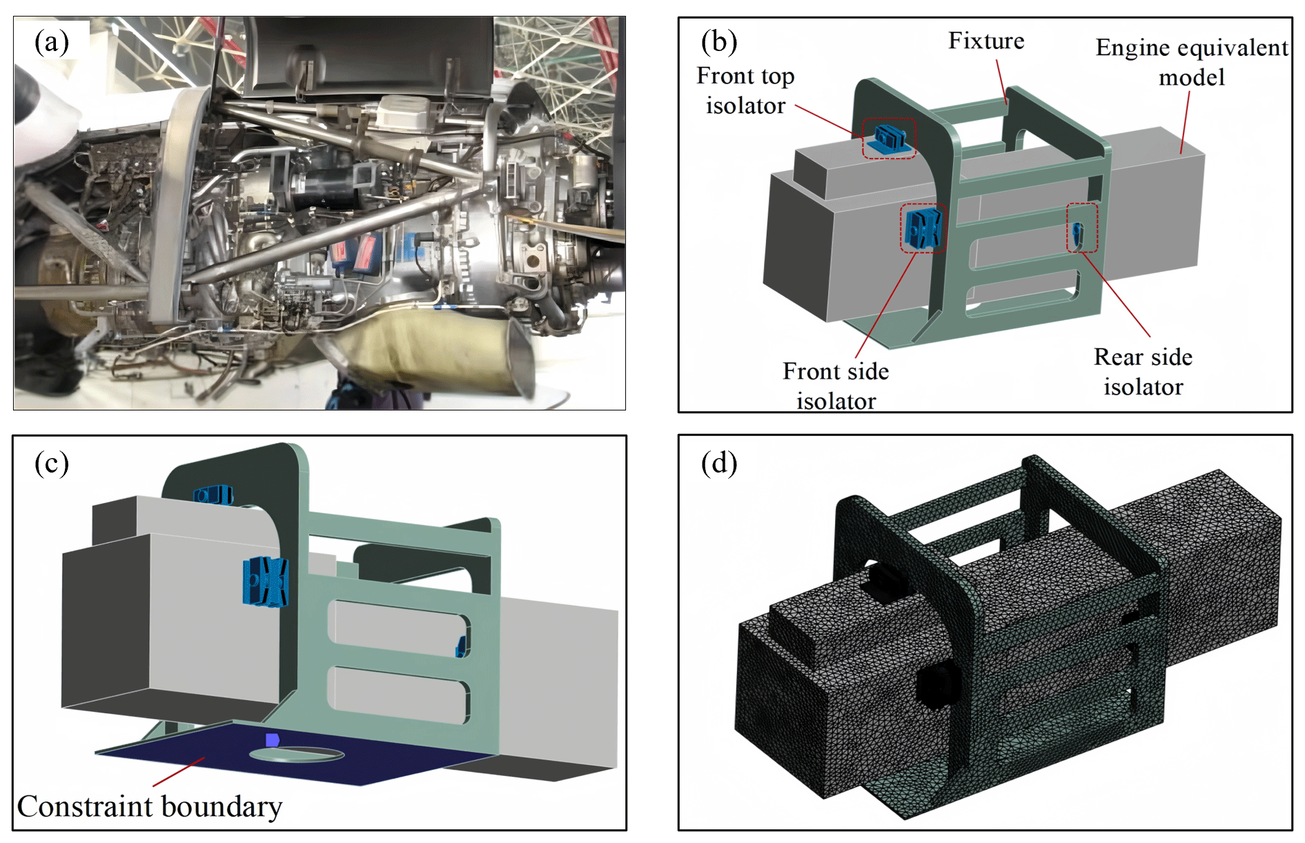
Figure 1Vibration isolation systems for turboprop engines. (a) Five-point vibration isolation system, (b) engine and fixture models, (c) constraint boundaries, and (d) meshing.
Table 1Structural material parameters.

Note that the backslash (\) stands for the fact that this isolator's modulus of elasticity differs with rubber hardness.
2.2 Fixture strength analysis
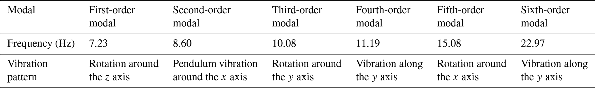
Modal analysis is used to calculate the intrinsic frequency and vibration form of the structure. Figure 1 contains the overall finite-element model of the engine prosthesis and the engine fixture. After modal analysis, the first–sixth-order vibration frequencies corresponding to the vibration patterns are obtained as shown in Fig. 2 and Table 2. The natural frequencies are 7.23, 8.60, 10.08, 11.19, 15.08 and 22.97 Hz, respectively. From the characteristics of the vibration mode, it can be seen that the larger displacement positions occur on the engine prosthesis and that the displacement of the fixture is very small, indicating that the stiffness of the fixture is larger. Avoiding influencing the vibration isolation performance of the vibration isolation system is advised.

Figure 2Modal computing cloud diagram of the (a) first-order modal, (b) second-order modal, (c) third-order modal, (d) fourth-order modal, (e) fifth-order modal and (f) sixth-order modal.
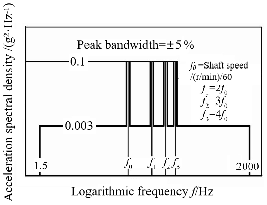
The damping efficiency test of the engine vibration isolation system generally adopts the test method of random vibration of the shaker. If the strength of the fixture is low, the large thrust force exerted by the shaker will easily damage the fixture and affect the test results. The vibration of the turboprop engine is characterized by broadband random vibration superimposed on narrowband random vibration. In this study, the turboprop engine is a six-bladed propeller and the rotational speed at rated power is 1020 rpm, so the first-order excitation narrowband frequency of the engine vibration is 102 Hz. The applied load spectrum curve is shown in Fig. 3.
The thrust force exerted by the shaker is expressed in Eq. (1):
where m is the total weight of the fixture and the engine dummy is 1940 kg, and the thrust applied by the shaking table from Eq. (1) is 75 857.88 N. The research object of this paper is a symmetrical five-point turboprop engine. As shown in Fig. 4, by applying the stress change cloud map in three directions to the five isolators on the fixture, the maximum stress in the three directions of x, y and z is 37.758 MPa. The maximum stresses in the x, y and z directions are 37.758, 10.686 and 53.082 MPa, respectively, which is far less than the allowable stress of the Q235 material of 235 MPa. Therefore, the design of the fixture structure is reasonable.

Figure 4Stress clouds in three directions: (a) x direction, (b) y direction and (c) z direction.
The analysis in Sect. 2 confirms that the designed aero-engine equivalent model and its fixture meet the strength requirements for the vibration experiment. In Sect. 3, the fabrication of the turboprop engine test structure is carried out first, followed by the design and completion of the random-spectrum vibration experiment of the turboprop engine across the full frequency domain according to the structural dimensions.
3.1 Trial modeling
Figure 5 shows the schematic diagram of the designed turboprop engine test structure. The test structure includes a mass equivalent body for the turboprop engine, fixture and five vibration isolators, of which there are three types. The turboprop engine adopts a double-mounting surface five-point method. This involves mounting one front-upper vibration isolator and two front-side vibration isolators on the front mounting surface for a total of three and mounting two rear-side isolators on the rear mounting surface. The vibration isolator of the turboprop engine serves as a mounting section, which is consistent with the actual layout of the turboprop engine.

3.2 Experimental program
To assess the vibration isolation performance of the system under the complex operating conditions of the turboprop engine, the test structure of the turboprop engine is analyzed using the vibration power spectral density map shown in Fig. 3, which depicts a combination of specific broadband and narrowband random vibrations. The necessary experimental equipment and testing instruments for conducting the vibration isolator transfer efficiency test include a 20 T water-cooled vibration table, B&K series acceleration sensor and data analysis software. Figure 6 depicts the frequency sweeping experimental bench, while Table 3 presents the essential information about the specific equipment and testing instruments used in the experiment.

Table 3Three methods for calculating natural frequency error analysis of blades.

Figure 7a, b and c illustrate the test conditions: vertical, transverse and longitudinal. The mounting knuckle is attached to the vibration table via a bolt structure. Figure 7d illustrates the layout of the measurement points for the three conditions. Points 1 and 2 are located at the front-upper end of the vibration isolator prosthesis and the frame, points 3 and 4 at the front-right end, points 5 and 6 at the front-left end, points 7 and 8 at the rear-right end, and points 9 and 10 at the rear-left end.

Figure 7Schematic diagrams of the three experimental conditions and the layout of their measurement points
Random vibration tests were performed based on the frequencies and vibration power spectral densities shown in Fig. 4a. The effective values of vibration response acceleration and vibration excitation acceleration were then measured for each damper within the 1.5–2000 Hz frequency range of random vibration.
The vibration isolation efficiency and the location of the first resonance occurrence were calculated for each of the three operating conditions using the data obtained from the experimental scheme in Sect. 3 and then analyzed and discussed.
4.1 Calculation of vibration isolation efficiency under random excitation
The vibration isolation efficiency is a critical metric for assessing the performance of vibration isolation. The time domain data collected are transformed using fast Fourier transform (FFT) to the frequency domain and then smoothed. Figure 8 shows the frequency domain graphs for the vertical, lateral and longitudinal acceleration response values at each measurement point. The calculation formula for vibration isolation efficiency is presented in Eq. (2):
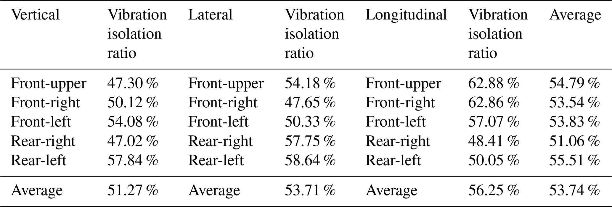
where gin is the control acceleration power spectral density, gout is the response acceleration power spectral density, and H is the frequency bandwidth. The vibration isolation efficiency of each vibration isolator under the three working conditions is calculated as shown in Table 4.

Table 4Efficiency of vibration isolation under three operating conditions.
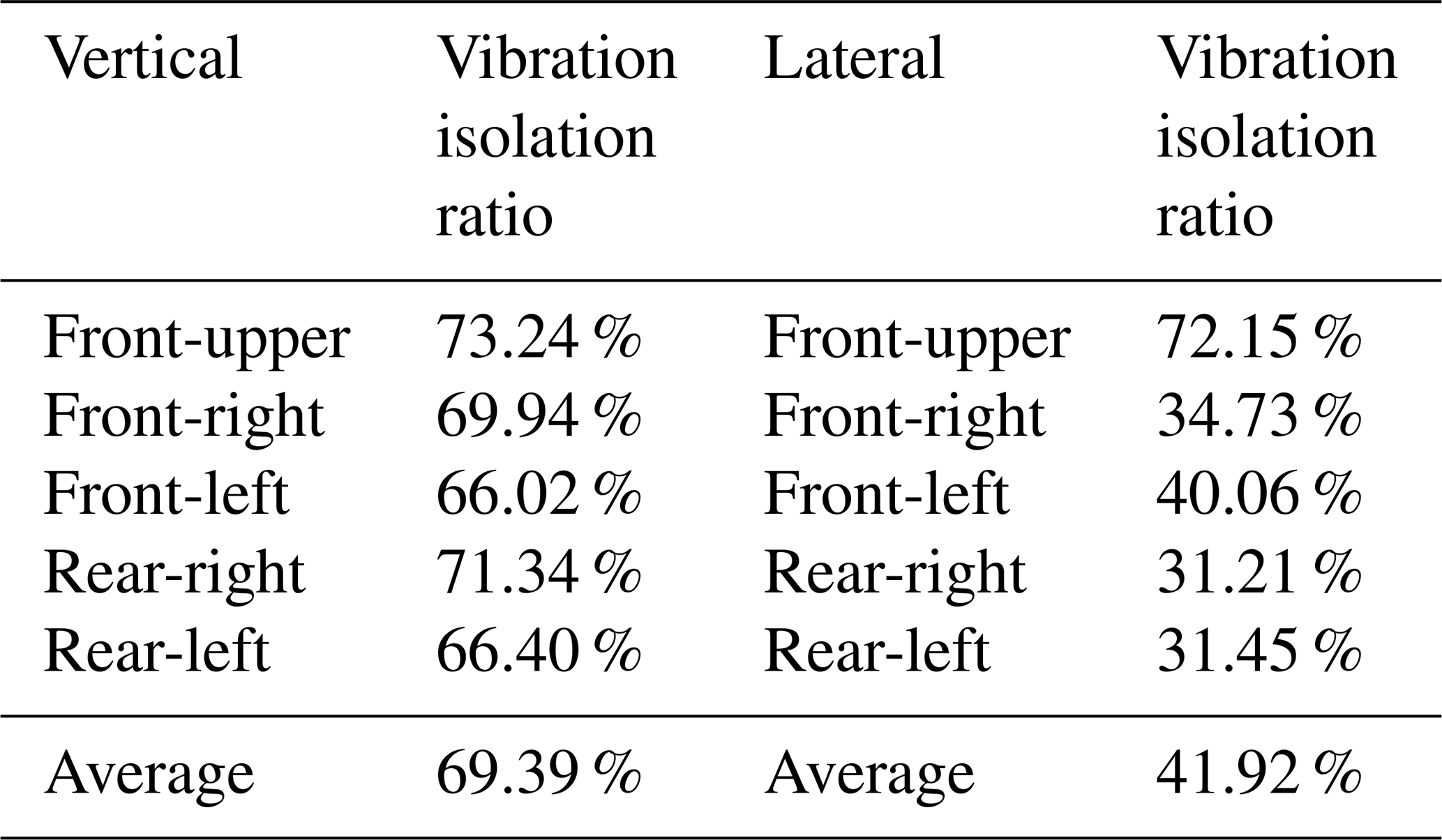
Additionally, two narrow frequency bands are designated for the rotational speed of the turboprop engine based on the engine's paddle rotation speed and the number of blades. These two bands are centered around 102 and 204 Hz. The excitation brought by the turboprop engine rotor shaft rotation is one of the key points of engine vibration isolation, and the longitudinal condition is not considered because it is perpendicular to the rotor shaft rotation direction, so the vibration isolation efficiency of the vibration isolation system in the vertical and longitudinal conditions is also calculated in this section, with the first and the second rotor shaft rotational speed frequency being the center of the bandwidth of the narrowband interval. Based on the bandwidth formula, with a peak bandwidth of ±5 %, the bandwidth range is calculated to be 96.9–107.1 and 193.8–214.2 Hz. The isolation efficiency of the vertical and longitudinal vibration isolation systems for the aero-turbine engine in the frequency band centered around 102 and 204 Hz is shown in Tables 5 and 6.
Table 5Narrowband vibration isolation efficiency with a frequency band center of 102 Hz.
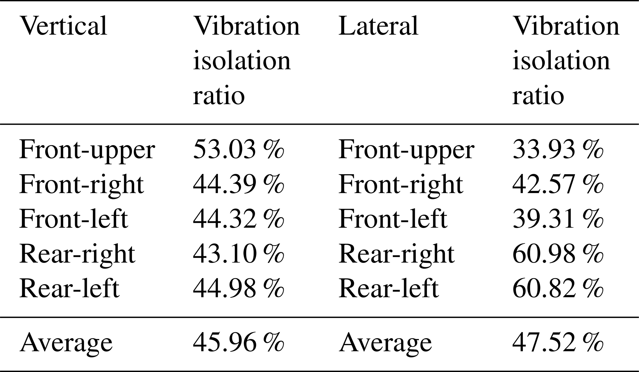
Table 6Narrowband vibration isolation efficiency with a frequency band center of 204 Hz.
Significant differences were observed in the vibration isolation performance of the system under different directional vibration conditions in terms of frequency distribution, as shown in Fig. 8. For instance, under the vertical vibration condition, the acceleration at the response end was larger than that at the excitation end within the 10–80 Hz frequency band, leading to amplified vibration transmission. Similarly, for transverse and longitudinal vibrations, the acceleration at the response end exceeded that at the excitation end within the 20–40 and 50–105 Hz frequency bands, resulting in amplified vibration transmission.
The data in Table 4 show that each vibration isolator has an isolation efficiency ranging from 45 % to 65 % within the frequency band of 1.5 to 2000 Hz. The overall average vibration isolation efficiency is 53.74 %. The highest average vibration isolation efficiency, 56.25 %, was observed in the longitudinal direction, which corresponds to the aircraft's traveling direction during flight. Based on the average vibration isolation efficiency of each type of vibration isolator in three different directions, it is observed that the efficiency is relatively consistent, ranging from 50 % to 55 %. When analyzing the data from Tables 5 and 6, it becomes evident that under vertical and lateral vibration conditions, the vibration isolation effectiveness of the narrowband interval with a center frequency of 204 Hz surpasses that of the narrowband interval with a center frequency of 102 Hz, exhibiting an average isolation efficiency of 55.66 %, which is higher than the overall average isolation efficiency across the entire frequency spectrum (1.5–2000 Hz). Conversely, the average isolation efficiency of the narrowband interval with a center frequency of 102 Hz is only 46.74 %, which is attributable to its proximity to the intrinsic frequency of the vibration isolation system.
4.2 Transfer function of the vibration isolation system for three vibration directions
Determining the transfer function of each isolator in the vibration isolation system across the entire frequency range and examining the resonance phenomenon resulting from low-frequency impacts can aid in assessing the adequacy of the vibration isolation system design. The vibration transfer efficiency curves for the vertical, transverse and longitudinal working conditions of various positional vibration isolators within the system are depicted in Fig. 9 across the full frequency range (1.5–2000 Hz). Additionally, the first resonance phenomenon location for each vibration isolator under the three working conditions is calculated and presented in Table 7.

Table 7First resonance position of each vibration isolator for three operating conditions.

The transfer function curves of various positions and types of vibration isolators in the vibration isolation system show close similarity in the same vibration direction, with the first resonance position being consistent. The average magnification at the first resonance position of the vertical, transverse and longitudinal directions in the vibration isolation system is 4.61, 2.57 and 3.14, respectively. In the three working conditions, the average magnification at the first resonance position of the front-upper, front-right, front-left, rear-right and rear-left vibration isolators is 2.17, 2.84, 3.89, 4.33 and 3.97, respectively. Compared to the front-left, the average magnification at the first resonance position of the front-right and rear-right isolators is 2.17, 2.84, 3.89, 4.33 and 3.97, respectively. The front-right and rear-right vibration isolators are of the same type as the front-left and rear-left vibration isolators. However, there is a significant difference in amplification and vibration isolation efficiency when they are equipped with the equivalent model of the turboprop engine, which is due to the fact that the turboprop engine body structure is not a symmetric structure. The analysis of the first resonance location under vertical and lateral working conditions reveals an average frequency of 45.07 and 32.66 Hz for the first resonance of each vibration isolator under vertical and lateral vibration conditions, respectively. This effectively avoids the 102 Hz first-order frequency of the rotary axis of the aircraft turbine propeller engine, suggesting a more reasonable design for the vibration isolation system.
This study focuses on the impact of various external excitations on aircraft turbine engines. The vibration isolation system must effectively address wide-frequency isolation and low-frequency impact resistance. Through a combination of simulation and experimental research methods, this paper explores the dynamic performance of a specific turbine engine vibration isolation system within the frequency range of 1.5 to 2000 Hz and presents the following conclusions:
- 1.
A test device equivalent to the vibration isolation system of an aircraft turbine engine has been designed. To mitigate the influence of equivalent test set modes on the test results, the first six modes of the equivalent test set are calibrated through numerical simulation to ensure avoidance of the frequency of the engine's paddle-rotating shaft modes. The maximum thrust of the shaker is calculated in combination with the test spectrum, and the structural reliability of the designed device is verified through hydrostatic analysis.
- 2.
To simulate the complex working conditions of aircraft turboprop engines, vibration tests were conducted in three directions using broadband random vibration superimposed on narrowband random vibration. The test results indicate that each vibration isolator has a vibration isolation efficiency ranging from 45 % to 65 %, with the highest average efficiency observed in the longitudinal direction, which corresponds to the traveling direction of the aircraft during flight. Furthermore, the average vertical and lateral resonance frequencies of the vibration isolation system are 45.07 and 32.66 Hz, respectively, which avoids the first-order frequency of 102 Hz of the rotating shaft of this type of aircraft turboprop engine, indicating that the design of the vibration isolation system is more reasonable.
One of the optimization objectives of the future vibration isolation system for this aero-turbine engine is to match the asymmetric structure of the turbine engine body and meet the vibration isolation requirements of different axial positions of the aero-engine rotor system in order to achieve a more coordinated global vibration isolation.
Ownership issues are involved, and therefore data cannot be disclosed.
HP: conceptualization; JY: data curation, formal analysis, and writing (original draft); GB: funding acquisition and methodology; BZ: investigation; HP: resources; DZ: software; RF and XD: validation; BZ and XD: visualization; and HP and GB: writing (review and editing).
The contact author has declared that none of the authors has any competing interests.
Publisher's note: Copernicus Publications remains neutral with regard to jurisdictional claims made in the text, published maps, institutional affiliations, or any other geographical representation in this paper. While Copernicus Publications makes every effort to include appropriate place names, the final responsibility lies with the authors.
The authors would like to thank anonymous reviewers for their valuable comments and suggestions that enabled us to revise the paper. This work was supported by the National Natural Science Foundation of China (grant nos. 52175091, 52075165 and 52375091), the Hunan Provincial Key Research and Development Program of China (grant no. 2022GK2023), the Hunan Provincial Natural Science Foundation (grant nos. 2023JJ30247 and 2023JJ50230), and the 14th Five-Year Plan Naval Advancement Research Foundation (grant no. 3020402030301).
This research has been supported by the National Natural Science Foundation of China (grant nos. 52175091, 52075165 and 52375091), the Hunan Provincial Key Research and Development Program of China (grant no. 2022GK2023), the Hunan Provincial Natural Science Foundation (grant nos. 2023JJ30247 and 2023JJ50230), and the 14th Five-Year Plan Naval Advancement Research Foundation (grant no. 3020402030301).
This paper was edited by Hui Ma and reviewed by two anonymous referees.
Afonso, F., Sohst, M., Diogo, C. M., Rodrigues, S.S., Ferreira, A., Ribeiro, I., Marques, R., Rego, F. F., Sohouli, A., Portugal-Pereira, J., and Policarpo, H.: Strategies towards a more sustainable aviation: A systematic review, Prog. Aerosp. Sci., 137, 100878, https://doi.org/10.1016/j.paerosci.2022.100878, 2023.
Bin, G., Li, C., Li, J., and Chen, A.: Erosion-damage-induced vibration response of aero-gas generator rotor system, Mech. Syst. Signal Pr., 195, 110298, https://doi.org/10.1016/j.ymssp.2023.110298, 2023.
Chen, W., Guo, Z., Chen, S., Cao, Y., Guo, X., Ma, H., and Wen, B.: Semi-analytic modeling and experimental verification of arbitrary aero-engine complex spatial pipeline, Appl. Math. Model., 131, 505–534, https://doi.org/10.1016/j.apm.2024.04.003, 2024.
Chen, X., Zhao, J., Jing, Y., Cao, X., Yuan, S., Luo, J., and Pu, H.: A novel permanent magnet vibration isolator with wide stiffness range and high bearing capacity, Mechatronics, 98, 103119, https://doi.org/10.1016/j.mechatronics.2023.103119, 2024.
Filippone, A.: Aircraft noise prediction, Prog. Aerosp. Sci., 68, 27–63, https://doi.org/10.1016/j.paerosci.2014.02.001, 2014.
Fu, J., Bai, J., Lai, J., Li, P., Yu, M., and Lam, H. K.: Adaptive fuzzy control of a magnetorheological elastomer vibration isolation system with time-varying sinusoidal excitations, J. Sound Vib., 456, 386–406, https://doi.org/10.1016/j.jsv.2019.05.046, 2019.
Ji, L., Luo, Y., Zhang, Y., Xie, S., and Xu, M.: A creative wide-frequency and large-amplitude vibration isolator design method based on magnetic negative stiffness and displacement amplification mechanism, J. Sound Vib., 572, 118185, https://doi.org/10.1016/j.jsv.2023.118185, 2024.
Kan, X. and Xing, T.: A novel mathematical model for the design of the resonance mechanism of an intentional mistuning bladed disk system, Mech. Sci., 13, 1031–1037, https://doi.org/10.5194/ms-13-1031-2022, 2022.
Kirmizi, M., Aygun, H., and Turan, O.: Energetic and exergetic metrics of a cargo aircraft turboprop propulsion system by using regression method for dynamic flight, Energy, 296, 131153, https://doi.org/10.1016/j.energy.2024.131153, 2024.
Kocak, K. and Yilmaz, C.: Design of a compliant lever-type passive vibration isolator with quasi-zero-stiffness mechanism, J. Sound Vib., 558, 117758, https://doi.org/10.1016/j.jsv.2023.117758, 2023.
Kwon, S. C., Jo, M. S., Ko, D. H., and Oh, H. U.: Viscoelastic multilayered blade-type passive vibration isolation system for a spaceborne cryogenic cooler, Cryogenics, 105, 102982, https://doi.org/10.1016/j.cryogenics.2019.102982, 2020.
Lee, H. M., Garg, S., Lim, K. M., and Lee, H. P.: Comparison of cabin noise of turboprop and turbofan aircrafts, Appl. Acoust., 214, 109651, https://doi.org/10.1016/j.apacoust.2023.109651, 2023.
Leng, D., Feng, W., Ning, D., and Liu, G.: Analysis and design of a semi-active X-structured vibration isolator with magnetorheological elastomers, Mech. Syst. Signal Pr., 181, 109492, https://doi.org/10.1016/j.ymssp.2022.109492, 2022.
Li, C., Bin, G., Li, J., and Liu, Z.: Study on the erosive wear of the gas-solid flow of compressor blade in an aero-turboshaft engine based on the Finnie model, Tribol. Int., 163, 107197, https://doi.org/10.1016/j.triboint.2021.107197, 2021.
Li, C., Bin, G., Li, J., Yang, P., and Wang, W.: Influence of inlet distortion on the wear of aero-compressor blades, Int. J. Mech. Sci., 230, 107551, https://doi.org/10.1016/j.ijmecsci.2022.107551, 2022.
Li, C., Bin, G., Li, J., and Yang, P.: Erosion wear characteristics of the aero-compressor blades in full speed range, Powder Technol., 418, 118227, https://doi.org/10.1016/j.powtec.2023.118227, 2023.
Liang, H., Fu, H., and Hao, G.: A miniaturized statically balanced compliant mechanism for on-chip ultralow wide-bandwidth vibrational energy harvesting, Mech. Sci., 15, 159–168, https://doi.org/10.5194/ms-15-159-2024, 2024.
Lin, D., Yang, F., Gong, D., and Li, R.: A new vibration isolator integrating tunable stiffness-damping and active driving properties based on radial-chains magnetorheological elastomer, Mech. Syst. Signal Pr., 183, 109633, https://doi.org/10.1016/j.ymssp.2022.109633, 2023.
Lu, Q., Li, C., Zhang, Y., Fang, H., and Bin, G.: Study on the vibration control method of a turboshaft engine rotor based on piezoelectric squeeze film damper oil film clearance, Mech. Sci., 14, 237–246, https://doi.org/10.5194/ms-14-237-2023, 2023.
Ma, H., Guan, H., Qu, L., Yang, T., Zeng, Y., Chen, Y., Zhu, Z., and Wang, H.: Blade-coating-casing rubbing induced vibration responses and wear characteristics, Tribol. Int., 194, 109571, https://doi.org/10.1016/j.triboint.2024.109571, 2024.
Oh, H. U., Lee, K. J., and Jo, M. S.: A passive launch and on-orbit vibration isolation system for the spaceborne cryocooler, Aerosp. Sci. Technol., 28, 324–331, https://doi.org/10.1016/j.ast.2012.11.013, 2013.
Roncen, T., Sinou, J. J., and Lambelin, J. P.: Experiments and nonlinear simulations of a rubber isolator subjected to harmonic and random vibrations, J. Sound Vib., 451, 71–83, https://doi.org/10.1016/j.jsv.2019.03.017, 2019.
Somanath, S., Marimuthu, R., and Krishnapillai, S.: Frequency domain analysis of pre-stressed elastomeric vibration isolators, Defence Technology, 25, 33–47, https://doi.org/10.1016/j.dt.2022.10.004, 2023.
Tahan, M., Tsoutsanis, E., Muhammad, M., and Karim, Z. A.: Performance-based health monitoring, diagnostics and prognostics for condition-based maintenance of gas turbines: A review, Appl. Energ., 198, 122–144, https://doi.org/10.1016/j.apenergy.2017.04.048, 2017.
Tong, W., Wei, B., Moshrefi-Torbati, M., Zhou, X., Yurchenko, D., and Yang, K.: Investigation of a monostable nonlinear vibration isolator with the inertia-elastic boundary, Commun. Nonlinear Sci., 132, 107887, https://doi.org/10.1016/j.cnsns.2024.107887, 2024.
Wang, J., Chen, Y., Pan, K., and He, X.: Test and analysis of vibration transmission characteristics of turboprop engine mounting systems, Noise and Vibration Control, 40, 250–255 + 259, 2020 (in Chinese).
Wang, P., Yang, Y., Ma, H., Xu, H., Li, X., Luo, Z., and Wen, B.: Vibration characteristics of rotor-bearing system with angular misalignment and cage fracture: Simulation and experiment, Mech. Syst. Signal Pr., 182, 109545, https://doi.org/10.1016/j.ymssp.2022.109545, 2023.
Wang, X., Yu, N., Wu, C., Zhang, W., and Yan, B.: Lever-type high-static-low-dynamic-stiffness vibration isolator with electromagnetic shunt damping, Int. J. Nonlinear Mech., 146, 104128, https://doi.org/10.1016/j.ijnonlinmec.2022.104128, 2022.
Yan, G., Qi, W. H., Lu, J. J., Liu, F. R., Yan, H., Zhao, L. C., Wu, Z. Y., and Zhang, W. M.: Bio-inspired multi-joint-collaborative vibration isolation, J. Sound Vib., 568, 118089, https://doi.org/10.1016/j.jsv.2023.118089, 2024.
Yan, K., Zhao, T. Y., and Ma, H.: Coupled vibration analysis of a rotating pre-twist blade-hub assembly with a setting angle reinforced by graphene nanoplatelets, Thin Wall. Struct., 195, 111287, https://doi.org/10.1016/j.tws.2023.111287, 2024.
Yang, P., Yue, W., Li, J., Bin, G., and Li, C.: Review of damage mechanism and protection of aero-engine blades based on impact properties, Eng. Fail. Anal., 140, 106570, https://doi.org/10.1016/j.engfailanal.2022.106570, 2022.
Yang, P., Yue, W., Chen, A., and Bin, G.: Influence of SiO2 and Al2O3 particles on erosion wear of aero-compressor blades, Wear, 530, 204992, https://doi.org/10.1016/j.wear.2023.204992, 2023a.
Yang, P., Li, C., Yue, W., Bin, G., and Chen, A.: Study on erosion wear characteristics of aero-compressor blades considering distortion degree, Tribol. Int., 189, 108895, https://doi.org/10.1016/j.triboint.2023.108895, 2023b.
Yang, T., Ma, H., Qin, Z., Guan, H., and Xiong, Q.: Coupling vibration characteristics of the shaft-disk-drum rotor system with bolted joints, Mech. Syst. Signal Pr., 169, 108747, https://doi.org/10.1016/j.ymssp.2021.108747, 2022.
Yang, Z., Zhang, R., Guo, Z., Guo, J., and Zhou, Y.: Research on the optimal speed of vehicles passing speed bumps on the highway based on an immune algorithm, Mech. Sci., 15, 315–330, https://doi.org/10.5194/ms-15-315-2024, 2024.
Ye, K., Ji, J. C., and Fitch, R.: Further investigation and experimental study of an origami structure-based quasi-zero-stiffness vibration isolator, Int. J. Nonlinear Mech., 157, 104554, https://doi.org/10.1016/j.ijnonlinmec.2023.104554, 2023.
Zhu, B., Zhang, X., and Zhao, T.: Nonlinear planar and non-planar vibrations of viscoelastic fluid-conveying pipes with external and internal resonances, J. Sound Vib., 548, 117558, https://doi.org/10.1016/j.jsv.2023.117558, 2023.
Zuo, S., Wang, D., Zhang, Y., and Luo, Q.: Design and testing of a parabolic cam-roller quasi-zero-stiffness vibration isolator. Int. J. Mech. Sci., 220, 107146, https://doi.org/10.1016/j.ijmecsci.2022.107146, 2022.
Zheng, G., Tan, H., Wu, Z., Zhang, F., Zhang, Y., and Luo, G.: Aerodynamics and bird ingestion characteristics of a bulge-adjustable turboprop engine inlet, Aerosp. Sci. Technol., 144, 108777, https://doi.org/10.1016/j.ast.2023.108777, 2024.
Zhao, T., Li, K., and Ma, H.: Study on dynamic characteristics of a rotating cylindrical shell with uncertain parameters, Anal. Math. Phys., 12, 97, https://doi.org/10.1007/s13324-022-00697-3, 2022.