the Creative Commons Attribution 4.0 License.
the Creative Commons Attribution 4.0 License.
 | 09 Jul 2024
Design and performance analysis of the 4UPS-RRR parallel ankle rehabilitation mechanism
Zongjia Wang
Changtao Yan
Zhiwei Wang
Ankle sprains are among the most common musculoskeletal injuries. Patients often require systematic rehabilitation training to expedite tissue healing and facilitate joint recovery. However, such training places high demands on medical staff, involves a lengthy process, requires considerable labor, and suffers from a shortage of skilled rehabilitation personnel. To address the need for effective ankle joint dysfunction rehabilitation training, this study analyzes the bone structure and movement mechanism of the ankle. Drawing on the parallel mechanism configuration, we propose a 4UPS-RRR parallel ankle rehabilitation mechanism. The rotation center of the rehabilitation mechanism can be highly coincident with the rotation center of the human ankle joint. The structure and degrees of freedom of the mechanism were designed and analyzed using screw theory. Additionally, a kinematic model of the mechanism was established. The mechanism's workspace was mapped by constraining the linear actuator length and spherical joint rotation angle. Furthermore, the mechanism's dexterity was assessed through the establishment of its Jacobian matrix, with the correctness of the kinematic model verified through simulation. Finally, an experimental platform was utilized to test the maximum range of robot motion, confirming the practicality of the ankle rehabilitation mechanism.
- Article
(6153 KB) - Full-text XML
- BibTeX
- EndNote


The joint system is a key part of the human movement system. The ankle joint plays a very important role in the processes of standing, walking, running, and jumping. The ankle is the most weight-bearing joint of the human body. The ankle joint is particularly prone to injury in daily life because of its heavy burden and high-frequency use in daily life. In addition, people that are over 60 years old accounted for 18.7 % of the population in all age groups according to the seventh national census, which means that the total number of elderly people in China has exceeded 260 million (Liu et al., 2022). With the increase in age, old people's physical strength and limb flexibility have different degrees of decline and are more prone to ankle joint injury (Zhou et al., 2016). In order to improve the motor function of the patients' ankle joint, a large number of repetitive rehabilitation training can be carried out on the patients'ankle (Jamwal et al., 2017). Traditional rehabilitation training therapy is mainly based on one-to-one treatment by rehabilitation trainers, which has disadvantages, such as low efficiency and high labor intensity. Moreover, the number of rehabilitation trainers in China is at only 50 000, with an average of 3.6 per 100 000 people, which is far lower than the international standard of 50 rehabilitation trainers per 100 000 people (Cheng et al., 2020).
To address the aforementioned challenges, researchers have delved into the realm of ankle joint rehabilitation robotics both domestically and internationally. Initially, ankle rehabilitation robots featured 1–2 degrees of freedom (DOFs), limiting their ability to offer comprehensive ankle joint rehabilitation (Choi et al., 2020; Blaya and Herr, 2004). The development of a 6-degree-of-freedom (DOF) ankle joint rehabilitation robot based on the Stewart platform has enabled the preservation of rehabilitation training data, facilitated remote communication, and empowered patients to conduct training sessions at home (Boian et al., 2004; Girone et al., 2001; Rosado et al., 2017). Jamwal et al. (2010) from the University of Auckland introduced a forward kinematics modeling approach for parallel ankle rehabilitation robots utilizing modified fuzzy inference. This robot integrates virtual reality, force feedback, and other technologies to enhance the engagement of patients during rehabilitation training. Nonetheless, the surplus degrees of freedom in this design can potentially lead to secondary joint damage alongside the complex structure and elevated costs.
In a bid to streamline mechanical structure and control expenses, Bian et al. (2010) devised an ankle rehabilitation robot featuring a remote rotation center. Comprising three linear actuators, a moving platform, and a static platform, this robot achieves alignment between the center of rotation and the ankle center. Dai et al. (2004) engineered ankle rehabilitation robots employing 3SPS-S, 3SPS-SP, 4SPS-S, and 4SPS-SP configurations. These mechanisms incorporate an intermediate branch chain to bolster stiffness and restrict freedom of movement, with detailed analyses conducted on stiffness and kinematics to fulfill ankle joint rehabilitation requirements. Li et al. (2020, 2016) introduced 2UPS-RRR and 3UPS-RRR ankle rehabilitation mechanisms, both featuring a branch layout of unconstrained chain with rotating pair and 3 degrees of freedom. By utilizing torque and tension pressure sensors, these mechanisms could monitor the robot's operational status while also analyzing its inverse solution and workspace.
In addition, there are some new ankle rehabilitation robots. Zeng et al. (2018, 2017) proposed an ankle rehabilitation robot powered by four pneumatic muscles, optimizing kinematic and dynamic performance and stress distribution to enhance robot stiffness. Wang et al. (2013, 2015) presented an ankle rehabilitation robot driven by ropes, effectively mitigating rigid impact on patients' ankle joints. However, precision control issues arose due to rope tension. Wang et al. (2016) developed the ankle joint rehabilitation robot MKA-III and a training model for simultaneous bilateral rehabilitation. They established an objective evaluation system and standards for quantifying patients' exercise capacity. Zhao et al. (2021) put forth a 3UPU ankle joint rehabilitation mechanism, refining the robot's size and workspace to meet rehabilitation needs. Zou et al. (2022) introduced a novel 3RRS parallel ankle rehabilitation robot, simulating circular trajectories and implementing a passive training strategy to limit experiment trajectory errors to being within 2.5 mm.
In conclusion, many institutions have conducted research on ankle rehabilitation robots with different results. Ankle rehabilitation robots have many problems, such as complex structural design, insufficient or redundant degrees of freedom, and non-existent rotational centering. Therefore, improvements should be made in structural design and human–machine adaptability. In terms of redundantly actuated parallel mechanisms, a parallel ankle rehabilitation robot is proposed in this paper. The advantage of using redundant drive is to achieve more accurate motion control by increasing the drive so as to improve the accuracy and stability of the robot's motion. This is particularly important for rehabilitation training tasks that require fine control and stable support. The redundant drive makes the robot structure more stable. When the patient loses balance or has abnormal movements, it can give them additional stable support to prevent the patient from being injured. It can also provide a variety of action combinations and control methods to adapt to the rehabilitation needs and characteristics of different patients. This flexibility allows the rehabilitation robot to be adjusted according to the patient's rehabilitation progress and individual differences so as to better meet the patient's rehabilitation needs, accelerate the rehabilitation process, and improve the rehabilitation effect.
The center of rotation can be adjusted for different patients, and the structure is simple and reliable. In order to ensure the correctness of theoretical calculation, the variation in linear actuator length was compared between theory and simulation. The workspace of the mechanism was obtained by solving the inverse solution of the mechanism. The theoretical workspace of the mechanism was compared with the physiological motion range of the ankle, and the uniformity of the motion space was analyzed. The motion state of the mechanism was simulated to ensure that the speed and acceleration of the robot were not sudden. Finally, the experimental prototype was made and the running condition of the prototype was evaluated.
2.1 The motion analysis of the ankle
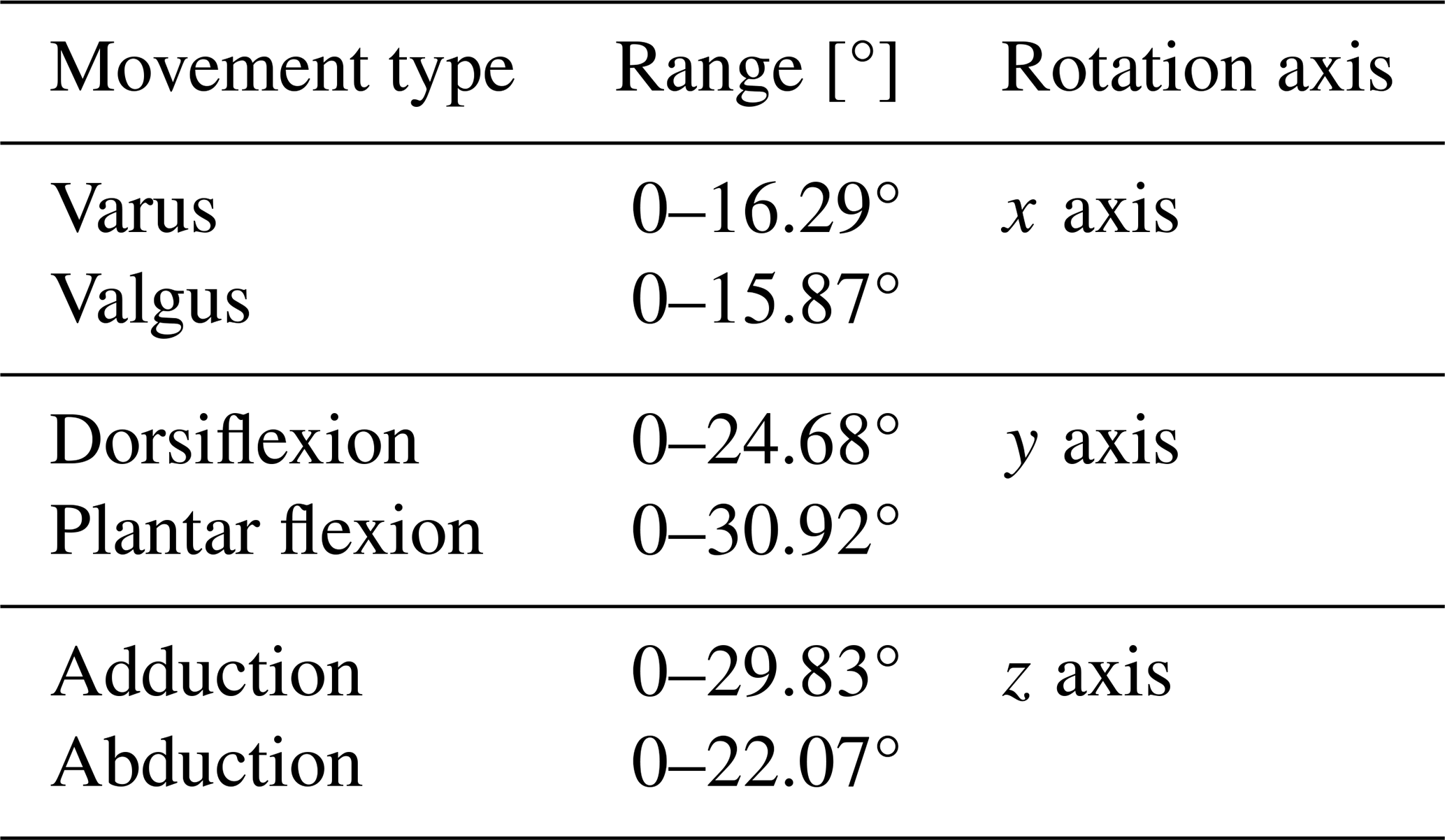
The movement of the astragalus can be regarded as the continuous rolling process of an irregular sphere in the mortise. In order to facilitate the research, the motion form of the ankle can be simplified as rotation around three perpendicular intersecting axes, as shown in Fig. 1b. Here, it is assumed that the center point of the ankle is the origin point, O; the direction of the foot is the X axis; the direction of the tibia is the Z axis of the coordinate system; and the coordinate axis perpendicular to the plane is the Y axis.

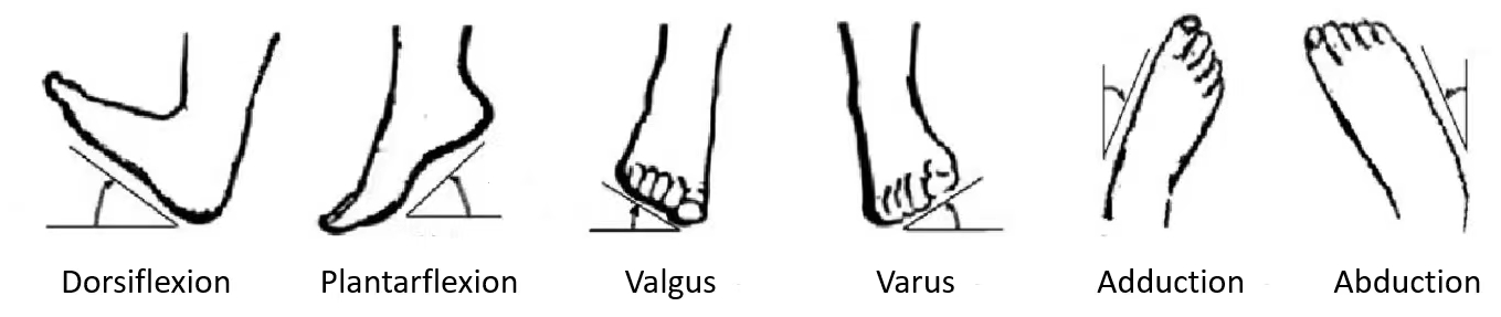
In daily activities, the daily basic movements of the ankle are composed of dorsiflexion/plantar flexion, varus/valgus, and adduction/abduction (Liao et al., 2018). Dorsiflexion/plantar flexion is the most important one among these movements.
There are differences in age, gender, physical development, and other aspects for different people, which also makes the range of motion of the ankle different. Obtained by consulting the data (Tsoi and Xie, 2009), the maximum range of motion of different ankle movements under normal conditions is shown in Table 1.
2.2 Design of ankle rehabilitation mechanism
In this paper, an ankle rehabilitation mechanism based on the parallel mechanism was designed. The specific structure is shown in Fig. 3. It is mainly composed of a fixed platform, moving platform, four UPS (hook joint–translational joint–spherical joint) branches with the same structure, and constrained branches. The translational joints in the middle of the branch are used as the driving pairs. The mechanism can rotate around three revolute joints in the motion space. During rehabilitation exercises, a foot fixation bandage is used to hold the patients' foot on a moving platform. Four linear actuators drive the moving platform in the space so as to drive the patients' foot movement.

Figure 3Ankle rehabilitation mechanism. 1: fixed platform, 2: hook joint, 3: linear actuators, 4: moving platform, 5: spherical joint, 6: constraint branched chain, and 7: foot fixation bandage.
The rehabilitation mechanism can switch between right-foot rehabilitation mode and left-foot rehabilitation mode by adjusting the four linear actuators. The mechanism uses four rods to support the moving platform, and the arrangement is symmetrical. In this way, the stiffness of the mechanism is stronger, the force of the whole moving platform is more uniform, and the mechanical properties are better.
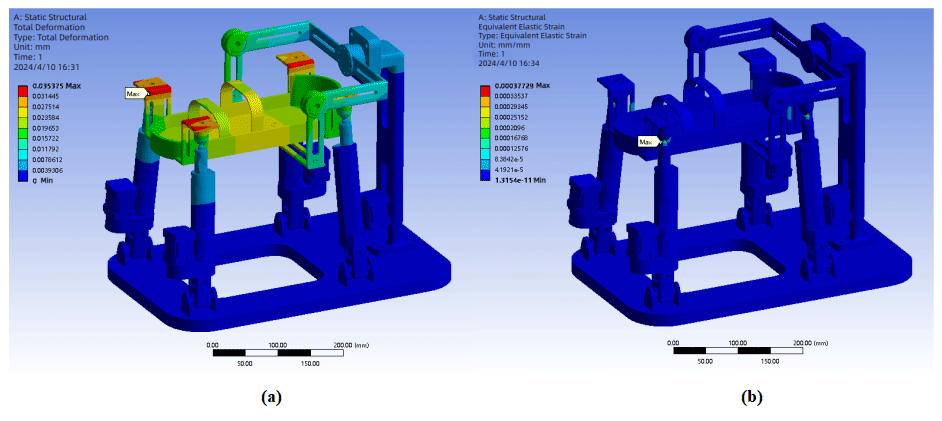
Figure 4Analysis results of the deformation and strain of the rehabilitation robot: (a) overall deformation analysis and (b) overall strain analysis.
2.3 Stiffness check of the ankle rehabilitation mechanism
The ankle rehabilitation robot needs to realize all-round rehabilitation training for patients with ankle rehabilitation training of different body sizes and under injury conditions. The robot will be affected by the load and its own gravity during the movement. The overall stiffness will change greatly. Good static and dynamic characteristics are the premise and foundation of ensuring the safety performance of the equipment. Therefore, it is important to check the stiffness of the robot reasonably.
In recent years, the survey statistics show that the average height of Chinese men is 169 cm, the average weight of men is 66.2 kg, and the average weight of women is 57.3 kg. In order to meet the rehabilitation training requirements of most people, 1.1 times the average height of men is taken as the ultimate height, that is, Hm=186 cm, and the body mass index (BMI) is taken as the highest index of obesity level, 29.9, to obtain the ultimate weight of Wm=103.4 kg. According to the survey, the proportion of the lower limbs of the human body is 34.4 %, and the pressure of the single leg on the ground is F=174.29 N. The static simulation process sets the single-leg load to an integer, 175 N.
In order to check the stiffness of the rehabilitation robot, the 3D model is imported to Workbench for static analysis. The material of the parts is set to aluminum alloy, and the mesh is adaptively divided. The boundary environment is set as follows: the bottom surface is fixedly supported, the Earth's gravity acceleration is vertically downward, the force load of the moving platform is increased by 25 N on the basis of 175 N and set to 200 N, and the direction is vertically downward. The solution results include overall deformation, equivalent strain, and equivalent stress. The solver is used to solve the problem. Finally, the overall deformation and strain analysis results of the rehabilitation robot are obtained, as shown in Figs. 4–5. The overall maximum deformation is 0.035 mm, and the maximum strain is 0.00038 mm mm−1. The value is small, and the overall deformation of the robot is small, which meets the stiffness requirements of the rehabilitation auxiliary equipment.
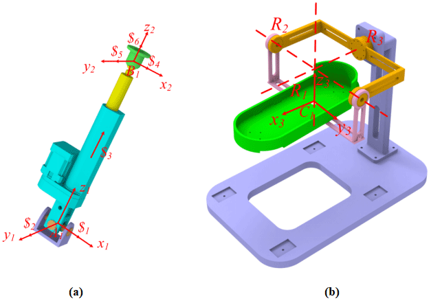
Figure 6Structure diagram of the drive branch and the constraint branch: (a) the screw system of UPS branch chain and (b) the screw system of constrained branch chain.
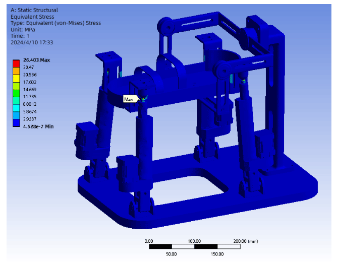
Figure 5 shows the overall stress distribution of the ankle rehabilitation robot. It can be seen that the maximum stress point of the robot is σm=26.403 MPa, which appears at the ball hinge. The overall stress of the robot is below 3 MPa, and the overall stress value of the robot is small. The yield strength of the aluminum alloy material is σb=280 MPa, and the safety factor of the robot is n=5. It can be seen that the allowable stress of the robot is 56 MPa, so the stiffness meets the design requirements.

Figure 7Diagrams of the parallel mechanism: (a) the specific structure of the parallel mechanism and (b) a simplified diagram of the parallel mechanism.
3.1 Analysis of ankle mechanism freedom
Since the robot has four identical UPS branch chains, one UPS branch chain in the mechanism is taken to form a branch screw system (Zhang et al., 2018). Assuming that the center point of the hook joint is A1 and the center point of the spherical joint is B1, the coordinate systems of A1 and B1 are established as A1 (x1, y1, z1) and B1 (x2, y2, z2), respectively, as shown in Fig. 6.
The kinematic screw system of driving the branched chain is shown as follows:
where a, b, and c are the coordinates of point B1 in the coordinate system A1 (x1, y1, z1).
According to Eq. (1), it can be calculated that the rank of the kinematic screw system of the driving branch chain is 6, so the driving branch chain is an unconstrained branch chain. The degree of freedom of the whole mechanism is determined by the constraint branch chain. Taking the center point of the moving platform as the origin of the coordinate system, the coordinate system C1 (x3, y3, z3) of the constraint branch chain is established as shown in Fig. 5b. The constraint branch chain is composed of three rotating joints with three axes orthogonal to each other, and the axis extension can converge to a point. The movement along three directions is constrained by the constraint branch chain, so the parallel mechanism is a three-rotation parallel mechanism.
According to the modified Kutzbach–Gruble equation, the DOF of the mechanism can be calculated as
According to the analysis results, this rehabilitation mechanism has 3 independent rotational degrees of freedom, which can satisfy the requirements of ankle rehabilitation training.


3.2 Inverse kinematics of the mechanism
Aiming at the special rehabilitation training form of the ankle joint, we adopt a 4UPS-RRR redundantly actuated parallel mechanism with four driving branches as the configuration of the rehabilitation mechanism. The specific structure is shown in Fig. 7 below. The rehabilitation mechanism is mainly composed of four parts: moving platform, fixed platform, driving branch chain, and constraint branch chain, as shown in Fig. 7a. The moving platform and the fixed platform are two quadrilaterals with different side lengths. They are connected by four UPS branches; that is, the upper end of the driving branch is connected to the moving platform through the ball hinge, and the lower end of the branch is connected to the fixed platform through the hook hinge. The middle part is the constraint branch chain. The lower end of the constraint branch chain is directly fixed on the fixed platform. The upper end is connected to the moving platform by two U-shaped brackets and three revolute pairs. Through the simultaneous elongation or contraction of the four driving branches, the height of the moving platform can be adjusted to adapt to different ankle heights. By driving the displacement change in the branch chain, the moving platform can be driven to rotate around the three axes (x, y, and z) shown in Fig. 7b.
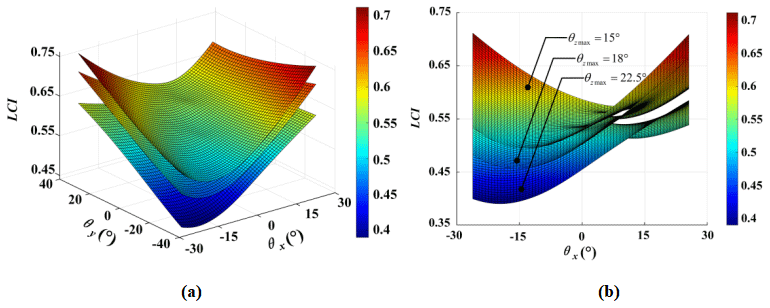
Figure 9The dexterity of the mechanism: (a) the spatial distribution of dexterity and (b) the planar distribution of dexterity.

In order to ensure the generality of the calculation, the mechanism is selected to be analyzed when the mechanism moves to a general configuration, as shown in Fig. 6. Assuming that the fixed platform is C; the moving platform is m; Ai, , is the center point of the fixed-platform U pairs; and Bi, , is the center point of the S pairs connected to the moving platform. Selecting the center point of the fixed platform as the center of the fixed coordinate system, O. The direction of the X axis is parallel to the connecting square of A1A2, the direction of the Z axis is perpendicular to the fixed platform, and the direction of the Y axis is determined by the right-hand rule. The establishment method of moving coordinate system is similar to that of fixed coordinate system. The length and width of the fixed platform are assumed to be E and e, and the length and width of the moving platform are D and d, respectively.
We assume that the attitude of the moving platform is z–y–x-type and the Euler angles are θz, θy, and θx. Then the rotation matrices around the Z axis, Y axis, and X axis, respectively, are
The rotation matrix to transform from the moving coordinate system to the fixed coordinate system is
Firstly, the fixed platform connection point Ai, ; the moving platform connection point Bi, ; and the position of the origin, O, of the moving coordinate system in the fixed coordinate system are determined to be , , and oC. The position of the connection point Bi, , of the moving platform in the moving coordinate system is assumed to be . The coordinates of the connection points of the moving platform in the fixed coordinate system can be obtained by the rotation matrix. The formulas are as follows:
It can be seen that the coordinate of the fixed platform connection points in the fixed coordinate system O (X, Y, Z) are
The coordinate of the connection points of the moving platform in the moving coordinate system o (x, y, z) are
By substituting Eqs. (6) and (7) into (5) and changing through rotation, the coordinates of can be obtained as follows:
The length of the four UPS branch chains (the distance between the center point of the hinge of the moving platform and the center point of the hinge of the fixed platform) can be expressed as follows:
By substituting Eqs. (6) and (7) into Eq. (5), it can be concluded that
As can be seen from Eq. (10), the length variation in the four linear actuators can be determined by the three Euler angles, θz, θy, and θx, when the length and width of the fixed and moving platforms of the parallel robot are determined. On the contrary, Eq. (10) can also be used to find the position and posture of the rotation center of the mobile platform by solving the nonlinear equations when the displacements of the four linear actuators are given.

4.1 Dimensional analysis of the mechanism
The workspace is a set of achievable ranges of reference points of the moving platform of the parallel mechanism. It is an important index fr measuring the performance of parallel robots. For this parallel mechanism, the attitude workspace (the range of angles within which a moving platform can rotate) needs to be studied. In order to ensure that the ankle rehabilitation mechanism designed in this paper can satisfy the needs, it is very important to analyze the workspace. According to Table 1, the motion angle range of the human ankle corresponds to the rotation angle range of the ankle parallel rehabilitation mechanism as θz being −29.83 to 22.07°, θy being −24.68 to 30.92°, and θx being −16.29 to 15.87°.
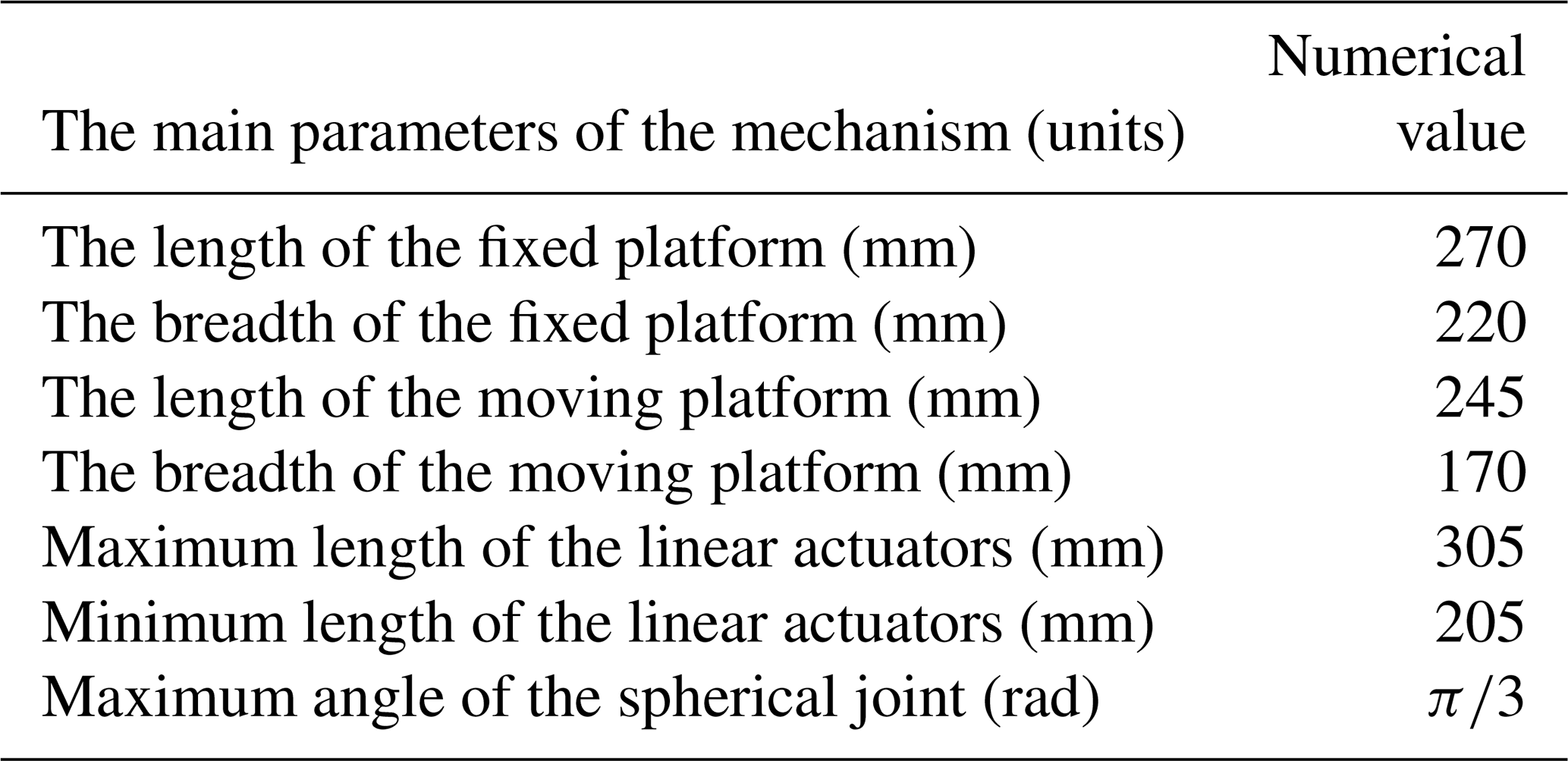
Referring to the Chinese national standard male body size (Zhao et al., 2019), some parameters are selected as shown in Table 2.
The selection of the main parameters of the mechanism should conform to not only the requirements of rotational performance, but also the size and proportion of the human body and satisfy the requirements to wear the mechanism. Among them, the length and width of the mobile platform are determined by the human body size in Table 2, the linear actuator is selected from the commonly used models on the market, and the length and width of the fixed platform are determined by the size limit of the mobile platform and linear actuators. Finally, the main parameters of the parallel mechanism are shown in Table 3.
4.2 The solution to the workspace
The workspace of the mechanism is solved by the inverse solution results and the parameters of the mechanism. The bar length of the mechanism is taken as the constraint condition, and the mechanism parameters are θz, θy, and θx, which continuously increase (Dong et al., 2022). An increment of θz, θy, and θx is 0.01 rad. The parameters are put into the inverse solution equation of the mechanism to verify whether the solution satisfies the bar length constraint condition of the mechanism. If the condition is satisfied, the bar length is a point in the workspace of the mechanism. The workspace obtained by MATLAB is shown in Fig. 8.
By comparing with Table 1, it can be seen that the rotation range of the moving platform in all directions can meet the requirements of ankle rehabilitation. Moreover, there is no singularity in the interior of the workspace, indicating that the mechanism has a good workspace.

4.3 The analysis of dexterity
Dexterity is an important index to measure the kinematic flexibility of a mechanism. The 4UPS-RRR parallel ankle rehabilitation mechanism is a pure rotation mechanism. In order to solve the dexterity of a rehabilitation mechanism, the Jacobian matrix of the mechanism is solved.
According to the inverse kinematic solution, once we obtain the output angles θz, θy, and θx, vector li, , is obtained using Eq. (10). So, we can change Eq. (10) to
The derivative of both sides of Eq. (11) with time leads to the following:
Namely, the following applies:
where is the Jacobian matrix of the parallel mechanism, with
We adopt the reciprocal of the condition number of the Jacobian matrix to measure the dexterity of the mechanism between the input and output. The dexterity of the mechanism kJ in one position is
where cond(J) denotes the condition for the matrix J, and cond. The value of kJ varies in the range [0, 1].
The mechanism dexterity graph obtained using MATLAB is shown in Fig. 9.
We chose different values of θzmax to analyze the kinematic dexterity of the rehabilitation mechanism. As shown in Fig. 9, the dexterity of the mechanism increases with the continuous decrease in θzmax. The dexterity values of the rehabilitation mechanism are mostly greater than 0.5 when θzmax=15°. The value range of kJ is [0, 1], and it changes with the change in the mechanism's pose. The dexterity index being closer to 1 corresponds to better dexterity. As shown in Fig. 9, the dexterity of the mechanism changes steadily and continuously, with uniform distribution and no mutation phenomenon. The results indicate that the mechanism has good dexterity and performance and can be applied in the rehabilitation of the ankle.

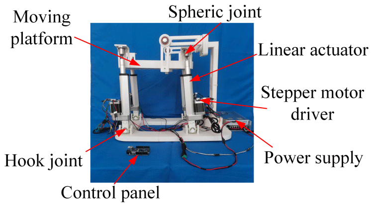
Figure 16Experimental prototype. The period of motion was set to 5 s for the rehabilitation exercise experiment.
5.1 Simulation of linear actuators' length
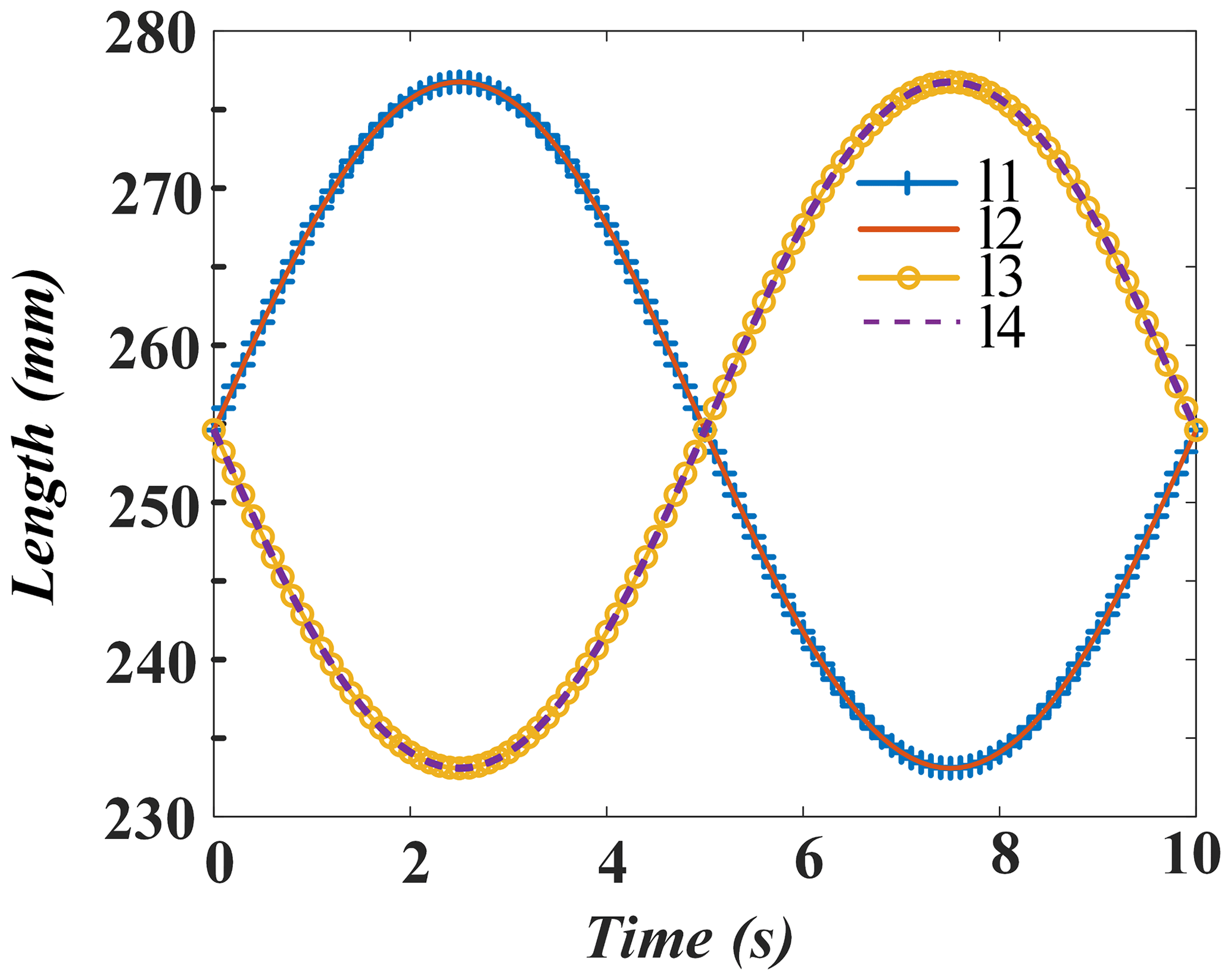
The kinematics of the mechanism is simulated with MATLAB. Firstly, according to the data in Table 2, the initial ankle height of 70 mm was selected to determine the initial position of the motion plane of the mechanism. The posture is set when the moving platform is parallel to the fixed platform. We take the simulation period to be 10 s. It is assumed that the angle θz of adduction/abduction of the mechanism is shown in Eq. (15).
The curve of the mechanism rod length changes with time, obtained by bringing the angle into the inverse equation, is shown in Fig. 10.
The angle θy of dorsiflexion/plantar flexion of the mechanism is shown in Eq. (16).
The curve of the rod length changes with time is shown in Fig. 11.
The angle θx of varus/valgus of the mechanism is shown in Eq. (17).
The curve of the rod length changes with time is shown in Fig. 12.
It can be seen from Figs. 10–12 that two pairs of four linear actuators always have the same motion rules. The same rules of motion are determined by the symmetrical structure. In this cycle, the displacement of the linear actuator changes uniformly and no mutation occurs. The change in the length of the linear actuator does not exceed the limit range, which shows that the movement rules of the linear actuators satisfy the basic requirements of the design.
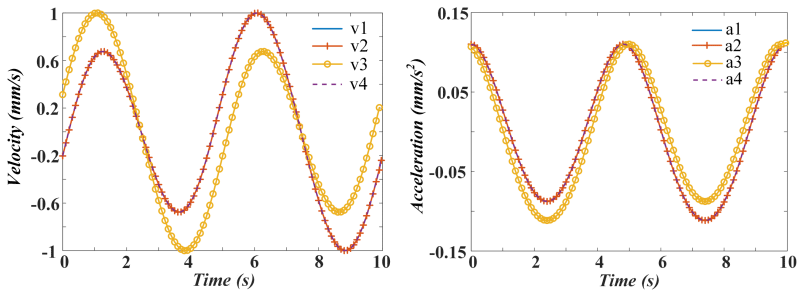
5.2 Simulation of the linear actuators' velocity and acceleration
It is assumed that the simulation period and angle planning are the same as those in the previous section. The velocity and acceleration of the linear actuators are simulated, and the results are shown in Figs. 13–15.
The curves of velocity and acceleration change periodically and are very smooth. Moreover, there are no mutation points in the whole process. The abovementioned conclusions indicate that the operation of the mechanism is relatively stable.
6.1 Prototype assembly and limiting angle experiment of rehabilitation mechanism
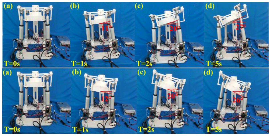
An experimental system consisting of a control panel, stepper motor driver, power supply, spherical joint, hook joint, linear actuators, and 3D-printed base frame has been built as shown in Fig. 16. Taking the right foot as an example, experiments were conducted on the adduction/abduction, dorsiflexion/plantar flexion, and varus/valgus of the human ankle. We observe the smooth operation of the prototype and whether it can meet the maximum range of motion of the human ankle.
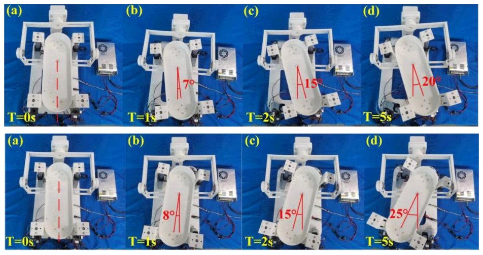
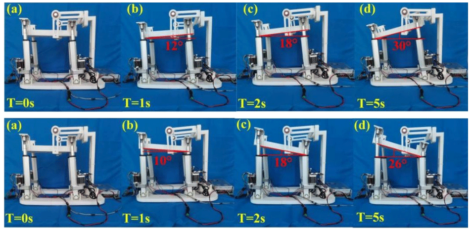
It has been proven that this rehabilitation mechanism can satisfy various rehabilitation movements of the ankle after being driven by four linear actuators and that the movement is relatively smooth. As shown in Figs. 17–19, the maximum rotation range of the mechanism can also fully cover the maximum motion range of the ankle is shown in Table 1. It can be proven that the parallel rehabilitation mechanism can satisfy the requirements of ankle rehabilitation.
6.2 Human–machine experiment of ankle rehabilitation mechanism
In order to verify the effectiveness, accuracy and human–machine fit of the overall function of the rehabilitation mechanism, the patient's foot is fixed on the moving platform using the strap in the right-foot rehabilitation mode, and the patient's calf should be kept upright as much as possible during the rehabilitation process. Firstly, the ankle dorsiflexion/plantar flexion rehabilitation exercise experiment was carried out. It is mainly to make the mechanism rotate around the axis of the ankle joint, that is, rotate around the y axis shown in Fig. 1b. This exercise is the most important ankle joint activity in work and life, and it is also the main way for people to bear weight when walking. The effect of rehabilitation is shown in Fig. 20.
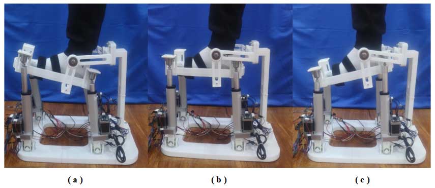
Figure 20The rehabilitation experiment of dorsiflexion/plantar flexion: (a) dorsiflexion, 20.03°; (b) initial position; and (c) plantar flexion, 18.24°.
Ankle varus/valgus injury is the main form of ankle injury. Therefore, the varus/valgus rehabilitation exercise of the rehabilitation mechanism is a very important rehabilitation mode in the rehabilitation training process, which mainly rotates around the x axis shown in Fig. 1b. This rehabilitation mode plays an important role in the recovery of ligaments and the training of peripheral muscle strength. The rehabilitation effect of the prototype is shown in Fig. 21.
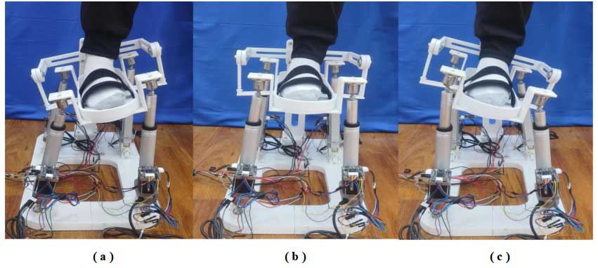
Figure 21The rehabilitation experiment of varus/valgus: (a) varus, 14.04°; (b) initial position; and (c) valgus, 16.53°.
Compared with the above two movements, the ankle joint has a lower frequency of internal/external rotation movements in life, and its rotation angle range is also the smallest, so the injury rate is also the lowest. It is mainly about the rotation of the z axis shown in Fig. 1b. This rehabilitation training mode can effectively improve the patient's joint flexibility, and the specific rehabilitation effect is shown in Fig. 22.
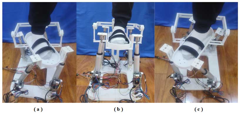
Figure 22The rehabilitation experiment of adduction/abduction: (a) internal rotation, 13.46°; (b) initial position; and (c) external rotation, 14.83°.
Figure 23 shows the comparison between the actual rotation angle value and the ideal trajectory result of the rehabilitation mechanism in the process of dorsiflexion/plantar flexion, varus/valgus, and internal rotation/external rotation rehabilitation training. The actual rotation angle of the mechanism is measured by DXL360S inclinometer, and the ideal trajectory is obtained by simulation calculation. It can be seen from Fig. 23 that although the acceleration of the local position is abrupt due to the gap between the parts in the prototype assembly and the weight of the parts themselves, the ideal trajectory and the actual trajectory curve cannot completely coincide, but the overall trend is the same. The amplitudes of the ideal trajectory and the actual trajectory are basically the same. There is also no collision between the components. Through the above analysis, it can be found that the rehabilitation mechanism designed in this paper can meet the needs of daily rehabilitation training of the ankle joint.

In order to lessen the impact on the workforce of rehabilitation practitioners and provide a higher-quality rehabilitation process for patients, an ankle joint rehabilitation robot based on a parallel mechanism is proposed. The motion mechanism of the ankle joint was analyzed, and the motion range of the ankle joint is given in detail for better kinematic characteristics in the rehabilitation process. Then, the structure of the ankle joint rehabilitation robot was designed, the degrees of freedom of the robot were calculated by screw theory, and the kinematics of the robot was analyzed by an inverse kinematics solution. The correctness of the theory is verified by numerical simulation. The simulation results show that the velocity and acceleration of the movement change periodically, and the curve is smooth without abrupt change. The experiments on the maximum running angle of the experimental platform show that the maximum rotation range of the rehabilitation robot includes the entire motion range of the ankle joint and that the running process is relatively smooth, which satisfies the requirements of the experiment. The feasibility of the ankle joint rehabilitation robot proposed in this paper was proven through the above analysis, which laid the foundation for the human–machine experiment in the future. It can act as a reference for future research of the ankle rehabilitation mechanism.
The next steps in the research should primarily focus on further investigating the materials and structure of ankle rehabilitation devices. Efforts should be made to minimize the size and weight of the devices without compromising their functionality. Extensive clinical trials should be conducted to record training data generated by different users during rehabilitation training with these devices, establishing a database for ankle injury patients' rehabilitation training. By analyzing the symptoms of patients stored in the database along with their rehabilitation training data, a basis for the subsequent work of healthcare professionals can be provided. Emphasis should be placed on developing human–computer interaction and rehabilitation assessment systems. The human–computer interaction system is a crucial component of rehabilitation devices, serving as a bridge for communication between patients, doctors, and rehabilitation devices to enhance the rehabilitation experience for patients. Currently, rehabilitation assessments rely mainly on subjective evaluations by physicians and patients. Establishing an objective rehabilitation assessment system can effectively monitor the rehabilitation status of patients in real time, aiding physicians in formulating targeted rehabilitation plans.
The data are available upon request from the corresponding author.
KS and ZW were the lead authors and provided the ankle rehabilitation robot in this paper. ZW organized the structure of the paper. CY directed the structural analysis of the ankle rehabilitation robot. ZW made contributions to presentation approaches for the ankle rehabilitation robot. ZW made contributions to the transmission system for the ankle rehabilitation robot.
The contact author has declared that none of the authors has any competing interests.
Publisher's note: Copernicus Publications remains neutral with regard to jurisdictional claims made in the text, published maps, institutional affiliations, or any other geographical representation in this paper. While Copernicus Publications makes every effort to include appropriate place names, the final responsibility lies with the authors.
This paper was edited by Med Amine Laribi and reviewed by three anonymous referees.
Bian, H., Liu, Y. H., Liang, Z. C., and Zhao, T. S.: A Novel 2-RRR/UPRR Robot Mechanism for Ankle Rehabilitation and Its Kinematics, Robot, 32, 6–12, https://doi.org/10.3724/SP.J.1218.2010.00006, 2010.
Blaya, J. A. and Herr, H.: Adaptive control of a variable-impedance ankle-foot orthosis to assist drop-foot gait, IEEE Trans. Neural Syst. Rehabil. Eng., 12, 24–31, https://doi.org/10.1109/TNSRE.2003.823266, 2004.
Boian, R. F., Bouzit, M., Burdea, G. C., and Deutschet, J. E.: Dual Stewart platform mobility simulator, The 26th Annual International Conference of the IEEE Engineering in Medicine and Biology Society, San Francisco, CA, USA, 1–5 September 2004, 4848–4851, https://doi.org/10.1109/IEMBS.2004.1404341, 2004.
Cheng, Z. M., Yin, T., Pan, H., Zhao, C., Yan, S. Q., Li, Y. W., and Huang, Z.: A 3-DOF parallel ankle rehabilitation mechanism, J. Mech. Eng., 56, 70–78, https://doi.org/10.3901/JME.2020.21.070, 2020.
Choi, H. S., Lee, C. H., and Baek, Y. S.: Design and Validation of a Two-Degree-of-Freedom Powered Ankle-Foot Orthosis with Two Pneumatic Artificial Muscles, Mechatronics, 72, 102469, https://doi.org/10.1016/j.mechatronics.2020.102469, 2020.
Dai, J. S., Zhao, T. C., and Nester, C.: Sprained Ankle Physiotherapy Based Mechanism Synthesis and Stiffness Analysis of a Robotic Rehabilitation Device, Auton. Robots., 16, 207–218, https://doi.org/10.1023/B:AURO.0000016866.80026.d7, 2004.
Dong, K. J., Li, D. L., Xue, X. Y., Xu, C., Wang, H. W., and Gao, X. M.: Workspace and Accuracy Analysis on a Novel 6-UCU Bone-attached Parallel Manipulator, Chin. J. Mech. Eng., 35, 1–13, https://doi.org/10.1186/s10033-022-00689-1, 2022.
Girone, M., Burdea, G., Bouzit, M., Popescu, V., and Deutsch, J. E.: A Stewart Platform-Based System for Ankle Telerehabilitation, Auton. Robots., 10, 203–212, https://doi.org/10.1023/A:1008938121020, 2001.
Jamwal, P. K., Xie, S. Q., Tsoi, Y. H., and Aw, K. C.: Forward kinematics modelling of a parallel ankle rehabilitation robot using modified fuzzy inference, Mech. Mach. Theory., 45, 1537–1554, https://doi.org/10.1016/j.mechmachtheory.2010.06.017, 2010.
Jamwal, P. K., Hussain, S., Ghayesh, M. H., and Rogozina, S. V.: Adaptive Impedance Control of Parallel Ankle Rehabilitation Robot, J. Dyn. Sys. Meas. Control., 139, 111006, https://doi.org/10.1115/1.4036560, 2017.
Li, J. F., Xu, C. H., Tao, C. J., Ji, R., Li, S. C., and Zhang, Z. J.: Design and Performance Analysis of a Parallel Ankle Rehabilitation Mechanism Based on 3-UPS/RRR, Acta Autom. Sin., 42, 1794–1807, https://doi.org/10.16383/j.aas.2016.c160144, 2016.
Li, J. F., Zuo, S. P., Zhang, L. Y., Dong, M. J., Zhang, Z. K., Tao, C. J., and Ji, R.: Mechanical Design and Performance Analysis of a Novel Parallel Robot for Ankle Rehabilitation, J. Mech. Robot., 12, 051007, https://doi.org/10.1115/1.4046511, 2020.
Liao, Z. W., Yao, L. G., Lu, Z. X., and Zhang, J.: Screw theory based mathematical modeling and kinematic analysis of a novel ankle rehabilitation robot with a constrained 3-PSP mechanism topology, Int. J. Intell. Robot. Appl., 2, 351–360, https://doi.org/10.1007/s41315-018-0063-9, 2018.
Liu, Q., Zuo, J., Zhu, C. X., Meng, W., Ai, Q. S., and Xie, S. Q.: Design and Hierarchical Force-Position Control of Redundant Pneumatic Muscles-Cable-Driven Ankle Rehabilitation Robot, IEEE Robot. Autom. Lett., 7, 502–509, https://doi.org/10.1109/lra.2021.3123747, 2022.
Rosado, W. M. A., Valdés, L. G. V., Ortega, A. B., Ascencio, J. R., and Beltránet, C. D. G.: Passive rehabilitation exercises with an ankle rehabilitation prototype based in a robot parallel structure, IEEE Lat. Am. Trans., 15, 48–56, https://doi.org/10.1109/TLA.2017.7827887, 2017.
Tsoi, Y. H. and Xie, S. Q.: Design and control of a parallel robot for ankle rehabilitation, Int. J. Intell. Syst. Technol. Appl., 8, 100–113, https://doi.org/10.1504/IJISTA.2010.030193, 2009.
Wang, C. B., Lu, Z. J., Duan, L. H., Liu, Q. Q., Sun, T. Y., Lu, Z. X., Li, W. G., Li, M., Shen, W. J., Shi, Q., Wang, Y. L., Long, J. J., Wei, J. J., Qin, J., and Wu, Z. Z.: Mechanism design of an ankle robot MKA-III for rehabilitation training, 2016 IEEE International Conference on Cyber Technology in Automation, Control, and Intelligent Systems (CYBER), Chengdu, China, 19–22 June 2016, IEEE, 284–289, https://doi.org/10.1109/CYBER.2016.7574837, 2016.
Wang, C. Z., Fang, Y. F., Guo, S., and Chen, Y. Q.: Design and kinematical performance analysis of a 3-RUS/RRR redundantly actuated parallel mechanism for ankle rehabilitation, J. Mechanisms Robotics., 5, 041003, https://doi.org/10.1115/1.4024736, 2013.
Wang, C. Z., Fang, Y. F., Guo, S., and Zhou, C. C.: Design and kinematic analysis of redundantly actuated parallel mechanisms for ankle rehabilitation, Robotica, 33, 366–384, https://doi.org/10.1017/S0263574714000241, 2015.
Zeng, X. F., Zhu, G. L., Yue, L., Zhang, M. M., and Xie, S.: A Feasibility Study of SSVEP-Based Passive Training on an Ankle Rehabilitation Robot, J. Healthc. Eng., 2017, 6819056, https://doi.org/10.1155/2017/6819056, 2017.
Zeng, X. F., Zhu, G. L., Zhang, M. M., and Xie, S. Q.: Reviewing Clinical Effectiveness of Active Training Strategies of Platform-Based Ankle Rehabilitation Robots, J. Healthc. Eng., 2018, 2858294, https://doi.org/10.1155/2018/2858294, 2018.
Zhang, H. Q., Fang, H. R., Fang, Y. F., and Jiang, B. S.: Workspace Analysis of a Hybrid Kinematic Machine Tool with High Rotational Applications, Math. Probl. Eng., 2018, 2607497, https://doi.org/10.1155/2018/2607497, 2018.
Zhao, C., Song, J. K., Chen, X. C., Chen, Z. M., and Ding, H. F.: Optimum Seeking of Redundant Actuators for M-RCM 3-UPU Parallel Mechanism, Chin. J. Mech. Eng., 34, 121, https://doi.org/10.1186/s10033-021-00651-7, 2021.
Zhao, C. Y., Ran, L. H., Liu, T. J., and Li, A. X.: Anthropometric Survey of Chinese Adult Population, Proceedings of the 20th Congress of the International Ergonomics Association, 9,434–441, https://doi.org/10.1007/978-3-319-96065-4_48, 2019.
Zhou, L., Meng, W., Lu, C. Z., Liu, Q., Ai, Q. S., and Xie, S. Q.: Bio-Inspired Design and Iterative Feedback Tuning Control of a Wearable Ankle Rehabilitation Robot, J. Comput. Inf. Sci. Eng., 16, 041003, https://doi.org/10.1115/1.4033900, 2016.
Zou, Y. P., Zhang, A. D., Zhang, Q., Zhang, B. L., Wu, X. S., and Qin, T.: Design and Experimental Research of 3-RRS Parallel Ankle Rehabilitation Robot, Micromachines, 13, 950, https://doi.org/10.3390/mi13060950, 2022.
- Abstract
- Introduction
- The motion analysis of the ankle and mechanism design
- Kinematic analysis of the ankle rehabilitation robot
- Workspace and dexterity of the mechanism
- Kinematic simulation of mechanism
- Rehabilitation mechanism prototype and experiment
- Conclusions
- Data availability
- Author contributions
- Competing interests
- Disclaimer
- Review statement
- References