the Creative Commons Attribution 4.0 License.
the Creative Commons Attribution 4.0 License.
 | 08 Jul 2024
Position control of a soft pneumatic actuator based on the pressure parameter feedback model (PPFM)
Yuwang Liu
Dongyang Zhang
Yi Yu
Peng Chen
Wenping Shi
Dongqi Wang
Soft pneumatic actuators have been one of the cores of soft robotics research and play a key role in driving the development of soft robots. Due to its high degree of internal nonlinearity and unpredictable deformation caused by environmental influences, the control model established for soft robots is still a difficult problem in terms of improving accuracy. This paper proposes a new positional control method for soft pneumatic actuators that are suitable for independent 3D deformation at any position and are the core units of continuous robots. The pressure parameter feedback model (PPFM) of the airbag is obtained by adjusting the pressure input through a proportional valve, collecting the air pressure inside the airbag and obtaining the airbag expansion height. The pressure input signal is changed according to the PPFM of the airbag to control the position of the soft pneumatic actuator. A modular experimental platform is built to validate the PPFM-based control strategy, which is able to adjust the position of the end center point of the soft pneumatic actuator in space with the discussed characteristics. It is demonstrated that the theoretical model can significantly improve the stability and accuracy of the soft pneumatic actuator motion.
- Article
(5930 KB) - Full-text XML
- BibTeX
- EndNote


The drive method as well as the form of the soft robot can have an impact on the design of the control strategy. Pneumatic methods are often used due to their ease of design and the simplicity of actuator fabrication (Xavier et al., 2021; Qi et al., 2020; Ren et al., 2020; Huang et al., 2018; Chen et al., 2022), and they can also provide relatively large drive forces. Researchers make soft actuator drives mostly in the form of pouch motors (Kim et al., 2021; Guo et al., 2020) or bellows (Childs and Rucker, 2020; Xue et al., 2018). Using specially designed anisotropic structures, soft actuators can display four different types of motions: extension, contraction, bending and twisting (Gorissen et al., 2017; Polygerinos et al., 2017). However, due to the material and structure of pneumatic actuators, drivers such as airbags or bellows can show large deformability and infinite degrees of freedom, which bring great uncertainty when moving soft robots (Cho et al., 2019), which seriously affects the controllability of soft robot motion as well as the control accuracy. Although there are many ways to control the motion of soft actuators, improving the control accuracy of pneumatic soft actuators is still a great challenge (Thuruthel et al., 2018). In order to be able to control the motion of soft robots, researchers have tried to establish a general model approach for soft actuators to design controllers (Sun et al., 2022; Wang et al., 2021; Adagolodjo et al., 2021; Zhang et al., 2022; Rouzbeh et al., 2018; Alici et al., 2018; Zhu et al., 2019).
Researchers have found that many soft robots can be approximated by a series of mutually tangent constant-curvature cross-sections; this is known as piecewise constant curvature (PCC) (Santina et al., 2020). This approximation is acceptable because the internal potential energy is uniformly distributed along each section, especially for gas-driven soft robots (Grube et al., 2022), and the assumption of PCC is also verified using the Hamiltonian principle in Yang et al. (2017). Traditional PCC models do not consider robot–environment interactions, and any additional deformation to the robot geometry is likely to invalidate the kinematics. To address this issue, Liu (2022) proposed an improved constrained kinematic PCC model that plays a role in the correction of PCC. The segmented constant curvature approach is feasible when inertia effects can be neglected (Xu et al., 2022). Therefore, PCC designs are influenced by the weight of the actuator and external loading (Gonthina et al., 2019).
For soft actuators with complex geometries or nonlinear materials (Xavier et al., 2020a; Wang et al., 2019), finite element analysis (FEM) has been used extensively to simulate soft robot dynamics (Martin-Barrio et al., 2020; Bieze et al., 2018; Tawk and Alici, 2020; Moseley et al., 2016), which provides a new way of thinking for modeling soft actuators. For example, a finite element model is proposed in Gharavi et al. (2022) for the dynamic finite element analysis of a semicircular fiber-reinforced actuator. In Pozzi et al. (2018), a soft pneumatic finger of a fiber-reinforced design is modeled using Vega FEM. The advantage of FEM over the traditional PCC modeling approach is that it can handle contact nonlinearities associated with environmental interactions. However, the computational burden of increasingly accurate models grows exponentially when using FEM (Jin et al., 2019).
Other areas of modeling have been explored by some researchers, including the use of artificial neural network (ANN) models to design controllers. Analytical models for soft pneumatic actuators are usually applicable only to assumptions based on certain simplified designs and structured environments; machine learning and deep learning approaches have a much larger scope of application for soft pneumatic actuators (Naughton et al., 2021). A neural network model is used to approximate the Jacobi function of soft pneumatic arms (SPAs) to derive the proportional–integral–derivative (PID) gain of the controller to attenuate external disturbances (Thuruthel et al., 2018). Nonlinearities caused by solenoid valves can also be modeled using data-driven machine learning techniques (Mohamed et al., 2020). However, neural networks require a large amount of training data, and the accuracy and precision of the model depends on the quality of the training set.
In conclusion, although there are many ways to build control models for soft robots, the control effect, especially the accuracy, can be greatly influenced by its structure, environment and other factors, and if the control model is too refined, it will generate an excessive computational burden.
In this study, a pressure parameter feedback model (PPFM)-based soft pneumatic actuator posture control strategy is proposed. In response to the problem of low control accuracy of the soft robot, this new positional control method is validated in a soft pneumatic actuator, aiming to simplify the model establishment while improving the stability and accuracy of the soft pneumatic actuator motion, which is shown in Fig. 1a. This soft pneumatic actuator is also applicable to other continuous robots with independent 3D deformation at any position and is the core unit of continuous robots, so this control strategy is theoretically applicable to other forms of soft pneumatic actuators as well. In this study, firstly, the corresponding kinematic model is established for the end center point pose of the soft pneumatic actuator. Second, the trapezoidal rising pressure input signal is generated by adjusting the proportional valve, and the internal air pressure and airbag expansion height are collected to obtain the parametric airbag parameter model, and the duty cycle of the pulse-width modulation (PWM) is applied to adjust the pressure input signal according to the PPFM of the airbag. Then, the theoretical position of the end of the airbag is estimated by the trajectory target point, and the theoretical time of solenoid valve conduction is obtained. The NOKOV motion capture system is used to reliably measure the position of the end of the soft pneumatic actuator, and closed-loop position control and trajectory tracking are achieved after error compensation under a proportional–integral (PI) controller. Finally, we built a soft robot posture control experimental platform and demonstrated that the tracking accuracy of the end point of the soft actuator on the target trajectory can be controlled between 0.3 mm.
This paper is organized as follows. Sect. 2 develops the corresponding kinematic model based on the end center point of the adopted actuator. In Sect. 3, a new positional control method is proposed, and the controller is designed. Section 4 performs valuation calculations for some parameters of the model. Section 5 is devoted to building an experimental platform and performing validation. Finally, Sect. 6 gives the conclusion.
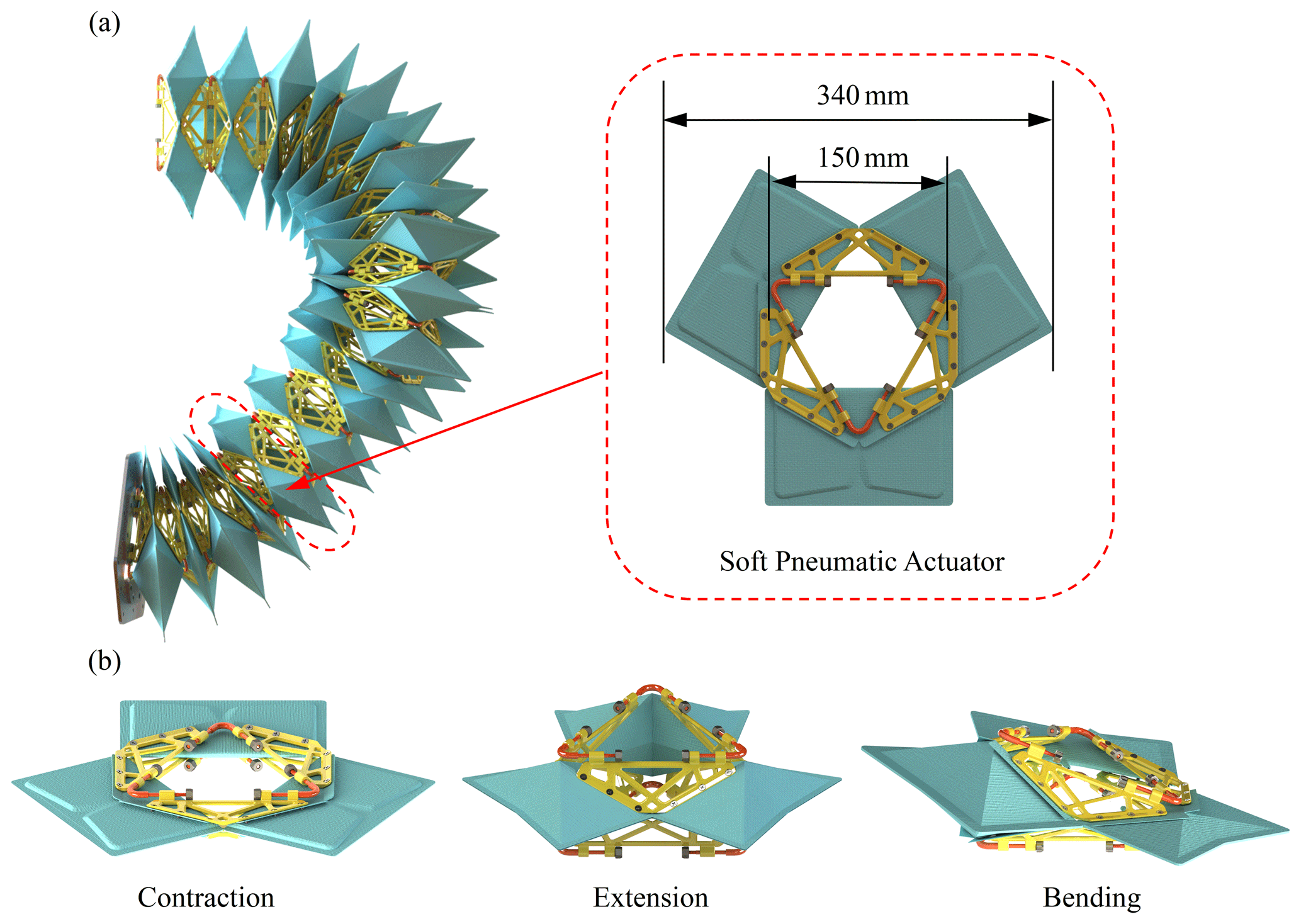
Figure 1The configuration, dimensions and control posture of soft pneumatic Actuator: (a) The drive unit in the pneumatic robotic arm. (b) Soft pneumatic actuator motion posture.
The present study requires not only the use of the positive kinematics of the soft pneumatic actuator to calculate the position of the airbag based on the onset time of the solenoid valve, but also the inverse kinematic model to calculate the onset time of the solenoid valve based on the target position point. The kinematics of the parallel mechanism has been analyzed in previous studies (Zhang et al., 2016; Huang et al., 2022; Salerno et al., 2016). In this study, the kinematic model of the soft pneumatic actuator is modified to a hexagonal base shape. For positive kinematics, in Zhang et al. (2016) and Salerno et al. (2016), since the module is driven by linear shape-memory alloy (SMA) and tendon actuators, the researchers calculated the position and orientation of the end-effector as a function of the input length variable and the input length variable as the distance between the top and bottom three vertices of the platform. However, a similar three-degree-of-freedom parallel mechanism is driven in this paper for a rotating platform, as shown in Fig. 1a. The kinematic model of the pneumatic actuator is obtained based on its attitude characteristics, giving the position and orientation of the end points of the pneumatic actuator as a function. Figure 1b also shows some positional states of the end points of this pneumatic actuator during its motion.
2.1 Forward kinematics
In order to drive the pneumatic module to a specific configuration, first a positive kinematic model of the mechanism needs to be studied. The model provides the position of the module base center o corresponding to the end-effector center o′ and the input tensions in the directions AA′, CC′, and EE′ as shown in Fig. 2. It consists of a hexagonal base plane, a hexagonal upper plane and three longitudinal airbags. In this model, it is assumed that each longitudinal airbag is connected to the upper plane and the base plane by a rigid joint. Although there is no central strut in the soft body, it is introduced into the model to mathematically provide kinematic constraints to prevent shear motion between the upper and base planes. It is equivalent to a passive retractable joint fixed at the center of the base plane and connected to the center of the upper plane with a universal joint. Thus, the upper plane has two rotational degrees of freedom and one translational degree of freedom.
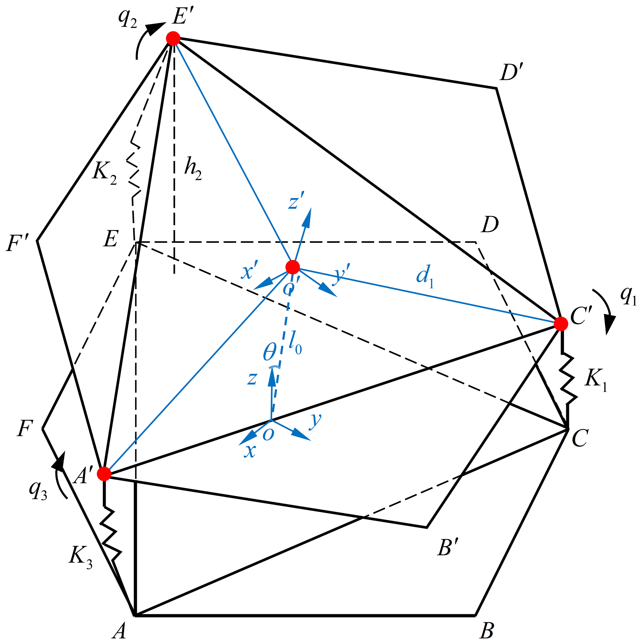
Two Cartesian coordinate systems o(xyz) and are set in this model. The joint A is located on the base plane represented by the soft actuator model x–y, while the joint A′ is located on the upper plane represented by the actuator x′–y′ . The origin o is the center of the base plane, while the origin o′ is the center of the upper plane, and each air chamber of the soft actuator is identified by a position vector Km (where ).
The robot posture can be calculated by analyzing the expansion height of each airbag, the overall bending angle of the soft pneumatic actuator and the curvature of the soft pneumatic actuator during the motion of the actuator. Accordingly, the relationship between the three airbags and the robot posture is modeled. Firstly, the intrinsic equation and strain conservation equation of this model are given as follows (Xavier et al., 2020b):
where , q is the curvature, Φ is the force arm along the pressure direction and τ is the PWM pressure signal input.
The distance from the center of the base to the center of the upper hexagon is l0, and the expansion heights of the three airbags of the pneumatic actuator are h1, h2, and h3, respectively. Therefore, we calculate the arc length of movement of the end-effector position o′ with respect to the initial state o, as follows:
where ψ is the curvature of the end-effector's position o′ with respect to the initial state o with the following value:
where d is the position of the end-effector o′ to the center point of the airbag, then Eq. (4) will be brought in and substituted into Eq. (3) to obtain the value of :
Equation (5) actually gives the relationship between the expansion height of the airbag h and the end point pose of the soft pneumatic actuator, which can be transformed into a forward kinematic problem if the expansion height h is known.
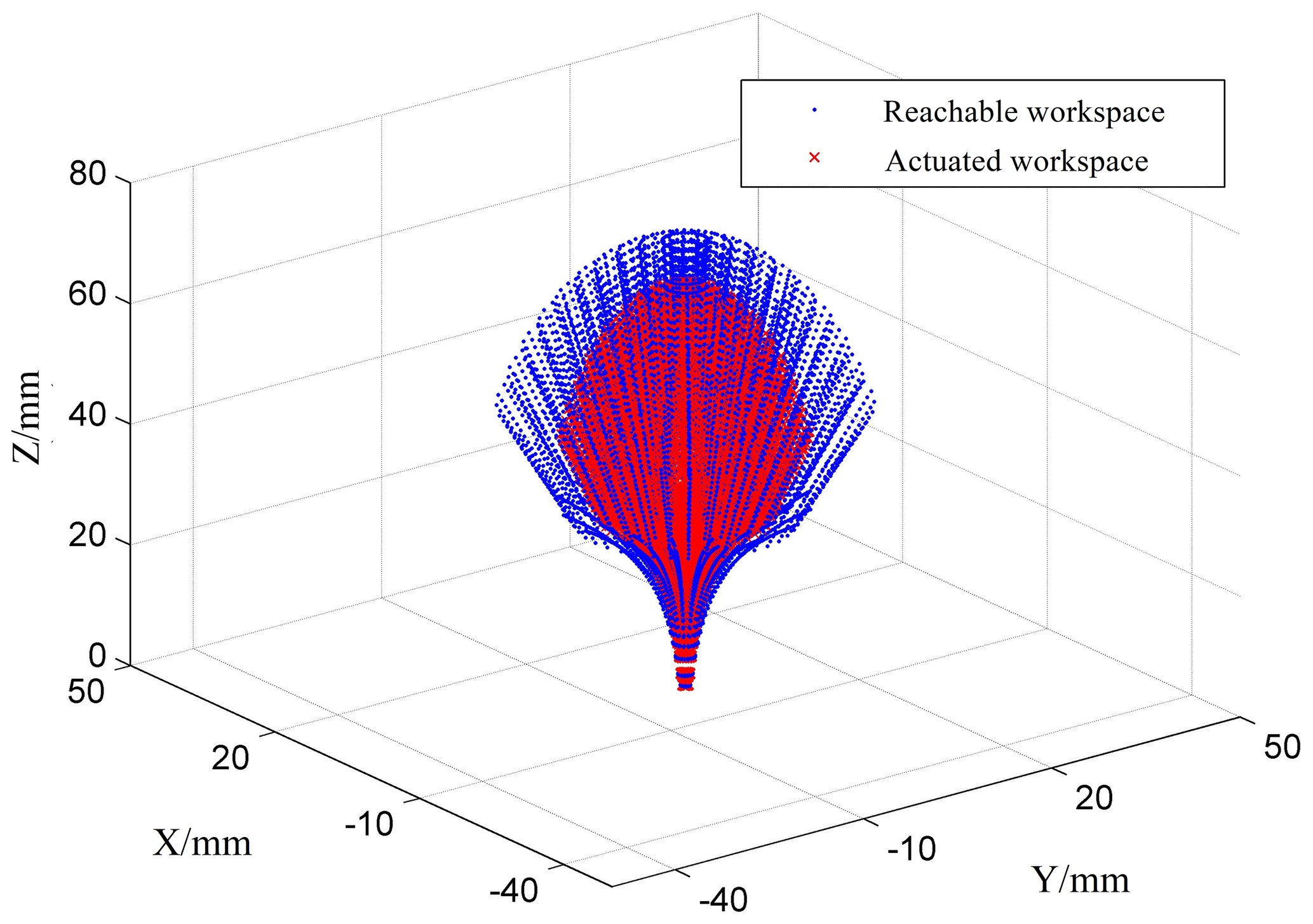
Using the positive kinematic equations, the reachable and pneumatic drive workspace at the end center point of the pneumatic actuator is derived, as shown in Fig. 3. In the simulation, we used the prototype dimensions of the module given in Fig. 1a. The achievable workspace illustrates the maximum movement space allowed by the actuator structure, while the achievable workspace shows the space in which the pneumatic actuator can work continuously and without interruption. There is a difference between the two workspaces because some air cavities of the driver expand to their maximum height when the end points reach the edge of the workspace and because the rigid links in the middle limit the motion state of the soft driver so that it cannot rotate along the edge of the workspace (the x and y directions recover a distance). Therefore, we make a distinction between the reachable workspace and the pneumatic drive workspace so that the drive always works in the drive workspace, and the accuracy and continuity of the drive's attitude control can be guaranteed.
2.2 Inverse kinematics
In order to calculate the expansion height of each air chamber of the soft pneumatic actuator from the position and offset angle of the end-effector, the inverse kinematics analysis of the model was carried out. The inverse kinematics of the soft pneumatic actuator is analyzed by geometric method to find the air chamber expansion height when the overall bending angle of the soft pneumatic actuator is known θ, the arc length of movement of the end-effector position o′ with respect to the initial state o and the curvature of the three air chambers q1, q2, q3.
The expansion heights of the three airbags are
This section introduces a controller design based on the PPFM. Firstly, the model needs to collect the relationship between the airbag input pressure and the expansion height; secondly, the pressure input signal of the airbag needs to be adjusted with PWM duty cycle according to the model; and finally, the PI controller with anti-saturation is designed to eliminate the error generated by the unmodeled part and the external disturbance.
3.1 PPFM
Based on the combination of a reliable kinematic model of the soft actuator, the position and direction of the end center point of the soft actuator can be obtained by the expansion height of the airbag. Therefore, it is possible to control the actuator motion by precisely adjusting the expansion height of the air chamber for this type of pouch motor fluid-driven pneumatic actuator.
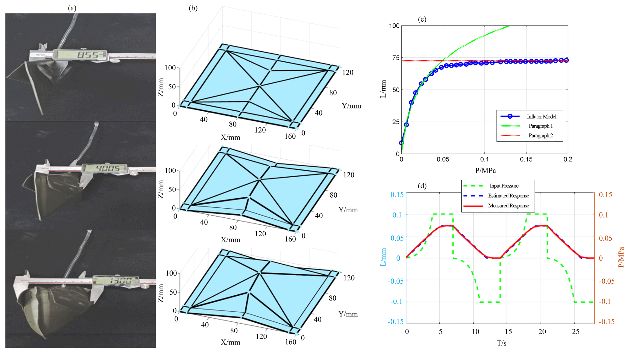
Figure 4PPFM design process: (a) airbag expansion data acquisition; (b) airbag expansion attitude model; (c) pressure-expansion height variation curve of airbag; (d) expansion curve regulated by PWM.
The pressure parameter model proposed in this study is designed with the pressure P input range between 0 and 0.2 MPa, and P is used as the input signal in sequence with a rising gradient of 0.006 MPa. The other parameters (airbag edge width, airbag edge length, wall thickness and gas flow rate) in the pressure parameter model are fixed, and only the expansion height H of the airbag depends on the value of the pressure P. As shown in Fig. 4a, the Vernier caliper reading increases as the input pressure increases. Next, the airbag expansion attitude is modeled in MATLAB based on the collected data, as shown in Fig. 4b.
The research performed a complete expansion experiment over the entire operating pressure range of the single gas chamber of the pneumatic actuator, and the measured values are shown in Fig. 4c. The results show that the relationship between the pressure P and the expansion height H is nonlinear. There are two regions approximated in the pressure–height relationship, where the slope of the expansion height H gradually decreases before the expansion height H starts to saturate. When the expansion height H starts to saturate, in this region, the expansion height H is not correlated with the pressure P, and it is seen that the airbag expansion has reached its maximum value.
Because the air pressure at any point in the airbag is independent of coordinates and only varies with time, it is possible to concentrate the air pressure value at one point. It can be seen that a second-order dynamics model of the expansion process of the airbag can be developed using the lumped element method, with the first segment being a linear approximation of the actual model of the soft pneumatic actuator. To account for the nonlinearities in the unmodeled part, they can be defined as perturbations to the linear model in the first segment. Similarly, unknown external perturbations can lead to instabilities in the soft robot.
After observing and calculating the characteristics of this model, the controller generates and controls the pulse width modulation of the voltage to the proportional valve send (PWM) input as needed. The digital inputs for the intake and exhaust valves allow the entry of outside air and the exhaust of air inside the airbag, respectively. A dynamic system is considered in the commissioning input signal, which can operate in one of η different modes at any given time. During the cycle of the PWM, the system can switch between mode 1 and η due to changes in the input provided to the system. The number of modes affects the control accuracy of the airbag – the more modes, the better the effect (but the calculation cost is also greater). The switching between mode 1 and η is based on the mode duty cycle (duration).
As shown in Fig. 4d, changes in the state of the single air chamber of the pneumatic actuator, including the internal pressure and the expansion height, can be observed. The results show that, according to PPFM, adjusting the duty cycle of the pressure input signal can extend the expansion time of the airbag moderately. First, the linear relationship between the expansion height H in the contraction and expansion zones of the single air chamber of the pneumatic actuator can be approximately satisfied in the relationship between time T, which is related to the PWM-tuned pressure P input signal applied inside the air chamber. Secondly, in the expansion saturation zone of the airbag and the vacuum contraction zone, the position of the single air chamber of the pneumatic actuator is independent of the pressure P. In this region, the end position of the airbag is characterized to reach the maximum edge of the workspace.
From the above, the single airbag dynamics model of the soft pneumatic actuator using the lumped element method can be described as a second-order dynamic system as follows:
where H(T) is the airbag expansion height; μ1, μ2, and μ3 are the constant model parameters; P(T) is the input pressure to the chamber; and Hmax is the maximum airbag expansion height.
The combined effect of the perturbation and the unknown perturbation external perturbation is added to the system model as follows:
where ΔT denotes the combination of perturbations, model uncertainty and unknown external perturbations.
The final set pressure input signal pattern τm is
where , and ax is the input signal duty cycle of the x mode.
3.2 Controller design
In actual motion, not only can the parametric model contain an unknown term which accounts for unmodeled perturbations and external disturbances, but also the dynamics model of the soft pneumatic actuator can have many uncertainties. In order to compensate the external perturbations of the model and the motion errors of the airbag, a PI controller is added to the original pressure parameter feedback model. Because, in the actual control system, for the differential it is easy to amplify the noise of the flow input signal, so the PI controller is added on the basis of the original pressure parameter feedback model so that the external disturbance of the model and the motion error of the air bag can be compensated.
Initially, the derivative and integral gains are set to zero. Inspired by the Ziegler–Nichols oscillation method, the proportional gain is increased until the control system reaches oscillatory behavior. Next, the tracking error is reduced by increasing the integral gain. The proportional and integral gains are then adjusted to improve the tracking performance. In the pressure control of a pneumatic actuator, high-frequency control errors are generated due to switching, measurement noise and set point variations. Therefore, the derivative mode produces high control signals that are not included in the controller design. When the output of the PI controller exceeds a reasonable range of the constraint, the integration calculation is actively stopped to prevent the integration from becoming too large.

The closed-loop control of the system is a saturation-resistant PI control. Figure 5 shows the control diagram of the system. PT indicates the position of the target tracking point, h is the desired expansion height of the airbag, h′ is the current expansion value of the airbag (captured by the NOKOV motion capture system), Δh indicates the error of the system and indicates the actual position of the end center point of the soft pneumatic actuator. The method firstly adopts the data-based method, then identifies the experimental model and finally compensates the feedback system for the position control error of the airbag.
In summarize, to design the controller for the airbag, the error coordinates are defined as follows:
where H(T) is the current inflation height of the airbag and Hd(T) is the desired inflation height.
Based on the defined error coordinates, the research define a PI-type function as follows:
where is the difference between the reference pressure P′(T) and the real-time pressure P(T); PC is the pressure compensation amount, and kp and ki are the proportional gain and integral gain of the controller, respectively.
In this section, the parameters of the designed model parameters are first estimated, and then in order to ensure that the gas flow rate in the pressure parameter model remains constant, only the expansion height H of the airbag depends on the value of the pressure P. The configuration of the air pump and the valve needs to be adjusted.
4.1 Parameter estimation
To estimate the system parameters μ1, μ2 and μ3, the research used Simulink for MATLAB for the identification of the model parameters. The model applies a rising gradient in the order of 0.006 MPa as input signal to check the linearity of the system and uses the measured output values to estimate the system parameters.

These parameters are valued according to the model shown in Fig. 6 for Sect. 3: , , and Hmax=73 mm.
4.2 Valve configuration
The solenoid valve is open/closed (0/1 control). When the valve of the compressor is open, the valve of the vacuum pump is closed and the pressure is increased according to the tuned PWM until the desired pressure is reached. When the valve of the compressor is closed, the valve of the vacuum pump is open until the pressure drops to the desired pressure. To prevent the solenoid valve from frequent switching operations, a dead zone is introduced near the set point where switching cannot be controlled. For a bidirectional solenoid valve system, we consider two states.
Solenoid valve conduction is represented as
When the solenoid valve is closed, it is represented as
where λ is the introduced buffer pressure.
In addition to a flow rate that decreases with pressure, air pumps are usually equipped with a pressure regulator or safety valve to avoid pressure buildup in the piping.
According to the conservation of mass, the net flow into the pneumatic actuator QA is (Xavier et al., 2020b)
where σ is the polytropic index; here, σ=1.4 (isentropic process), and VA is the actuator volume due to , where V′ is the volume of air consumed in one drive cycle from atmospheric pressure Pa to the desired pressure P′ .
For every minute N of the drive cycle, the flow rate required from the air pump to keep the receiver constant Qr is
According to ISO standard 6358 (Joshi and Paik, 2021), the flow rate through the valve is
where u is the duty cycle, Ph and Pl are the absolute upstream and downstream pressures, C is the sonic conductance, and b is the critical pressure ratio. When charging, Ph=PR, Pl=PA, where PR is the receiver pressure and PA is the actuator pressure. When discharging, Ph=PA and Pl=Pa .
In this section, the PPFM compensated by PI controller is applied to the filling and discharging module to track linear and circular trajectories. In the experiments, a soft pneumatic actuator is used whose design is shown in Fig. 1a. There are two pairs of three proportional valves and solenoid valves acting on three different soft actuator air chambers, respectively.
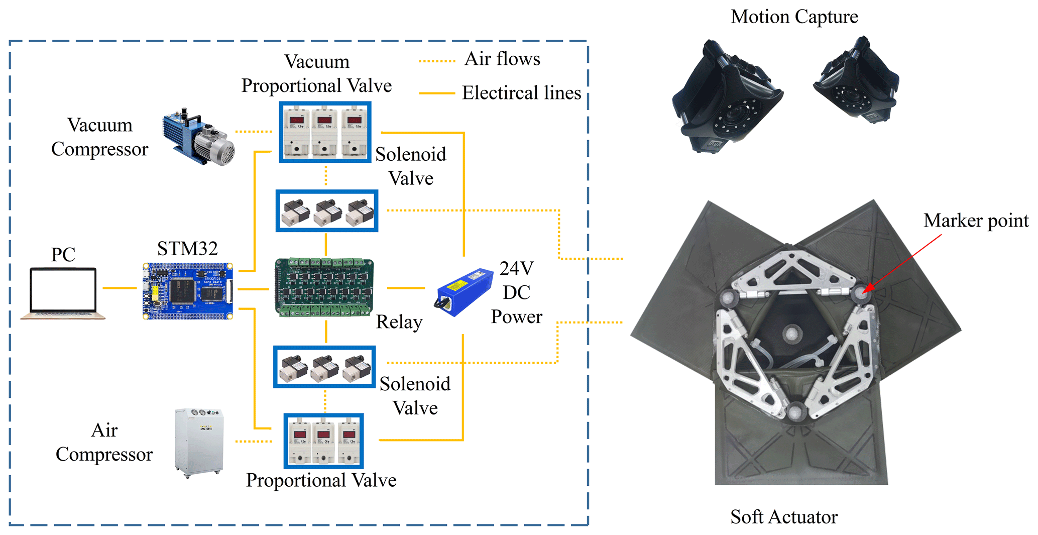
Although much depends on the materials used and the seal, the air chamber used can handle up to 0.5 MPa input pressure before bursting, and in Fig. 4 it can be seen that 0.1 MPa of air pressure is sufficient to reach saturation. Therefore, for safety reasons, the research used a pressure gauge (SMC Corporation) to supply no more than 0.2 MPa air pressure to the control valve. The output pressure is regulated by driving a proportional valve with the 5 V PWM signal by converting the 3.3 V STM32 PWM signal to a 5 V PWM signal using a transistor array. In addition, a solenoid valve is being connected before the proportional valve to distinguish the inflation process of the flexible actuator from the deflation process. The PWM signal based on PI controller compensation is generated by running on the STM32 board and then continuously cyclically transmitted to the proportional valve, and the controller controls the on/off and blocking of the solenoid valve through the MOS-tube integrated relay board. Finally, the PC is used to select the operation mode of the soft drive, and the whole experimental setup is shown in Fig. 7.
In order to track a given trajectory, the inverse kinematic model proposed for this soft pneumatic actuator needs to be used to calculate the expansion height of each air chamber and thus determine the turn-on time of the solenoid valve. Furthermore, as mentioned in Sect. 3 of the methodology, first marker points are placed at the end of each air chamber on the soft pneumatic actuator and at the center point of the actuator end, and the actual position of the expansion point is captured using the NOKOV motion capture system, with the error between the height set point of the PI controller tuned by the Ziegler–Nichols oscillation method and the actual airbag expansion height. The PWM input signal is then generated by the controller calculation and drives the proportional valve. Finally, the researchers record the position of the actual end center point of the measured soft pneumatic actuator and compare it with the target trajectory.
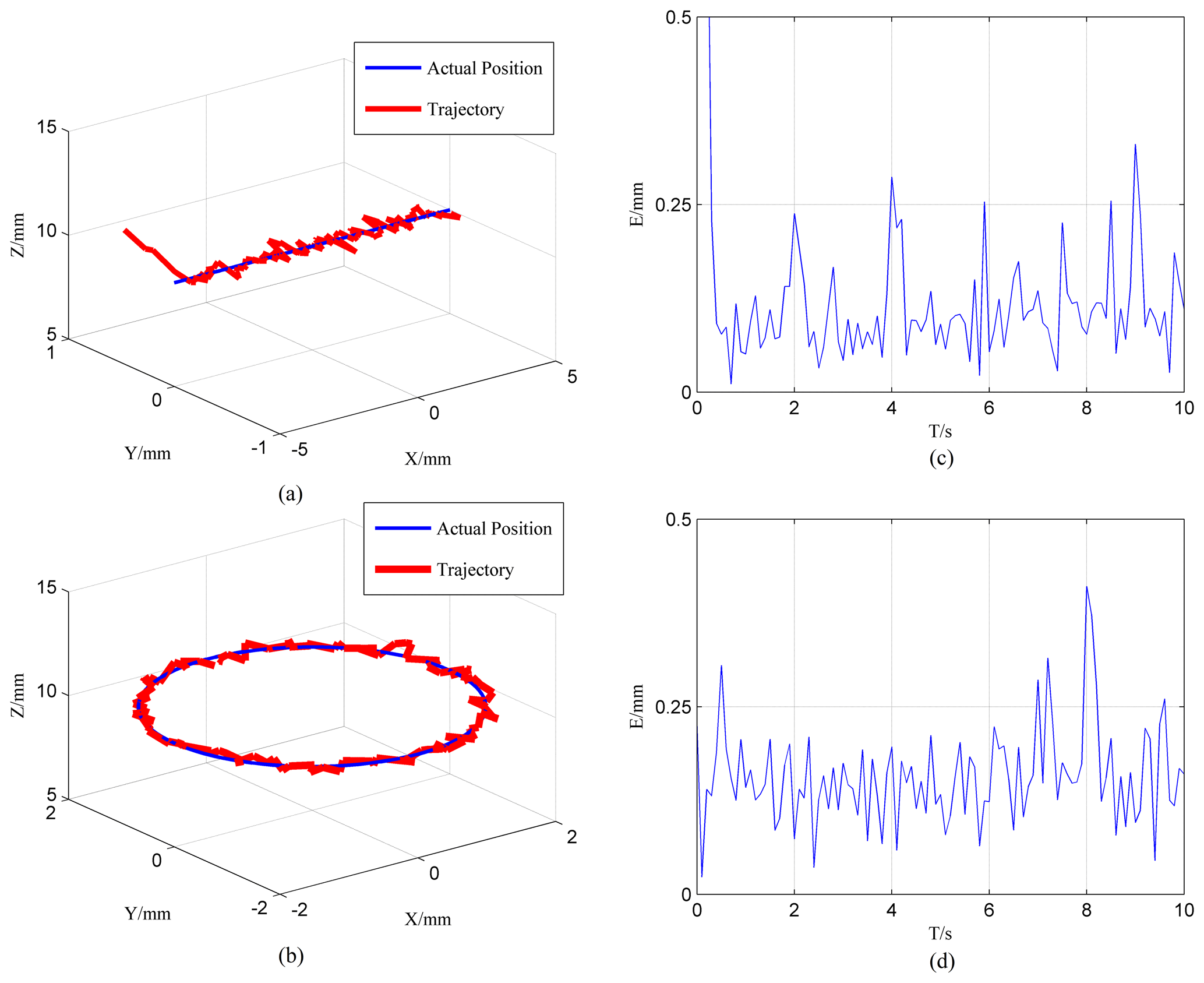
Figure 8Trajectory tracking experiment results: (a) 3D horizontal linear path tracing; (b) 3D horizontal circle path tracking; (c) horizontal straight line horizontal straight line path tracking error; (d) horizontal circle path tracking error.
To validate the proposed PPFM-based soft pneumatic actuator positional control method, the experimental design tracks two different trajectories: a horizontal straight line with a length of 10 mm and a circular path with a diameter of 4 mm. As shown in Fig. 8, the module successfully tracks the trajectories by reaching 0.8 mm s−1 end-effector speed. In addition, the research gives the tracking error for the end center point motion of the soft pneumatic actuator.
From Fig. 8a and b, it can be seen that the soft pneumatic actuator has some oscillation in all directions. The amplitude of the three directions is larger at the beginning of the linear trajectory, which is caused by the position error of the initial position of the soft pneumatic actuator at this time. The end point of the soft pneumatic actuator always oscillates with time during the whole motion process, and the vibration is caused by the air pressure shock when the solenoid valve is on. The actual motion curve during the movement and the set curve real-time error are shown in Fig. 8c and d. As can be seen from the figure, the error amplitude of the end center point of the actuator is less than 0.3 mm in the process of linear following movement, and 30 shows a certain oscillation shape on the average value of around 0.1 mm. The percentage error is within 3.4 %. In the case of circular following motion, it shows a certain oscillation shape above and below the average value of 0.2 mm. The percentage error is within 3.8 %.
In this study, a soft pneumatic actuator positional control strategy is proposed to obtain high controllability of its volume and nonlinearity in the face of an unknown parameter model of the soft pneumatic actuator. After identifying the feedback model of the pressure parameters of the airbag, the PWM pressure input signal is adjusted by the model, and the high-precision control of the soft pneumatic actuator is achieved with the compensation of the PI controller. The forward and reverse kinematics of the actuator model are modeled, and the trajectory can be tracked accurately under the condition of ensuring stability; the error can be reduced to within 0.3 mm for its workspace. Based on the closed-loop trajectory tracking results, it is demonstrated that the controller based on the pressure parameter model can perform high-precision positional control of the soft pneumatic actuator. This posture control strategy can also be applied to other soft robots with soft pneumatic actuators and has a significant effect on improving their stability and accuracy.
All the data used in this paper can be obtained by request from the corresponding author.
YL provides financial support for the research. DZ proposes the control strategy and completed the paper. YY and WS completed the experiments and simulations. PC and DW reviewed and polished the paper.
The contact author has declared that none of the authors has any competing interests.
Publisher's note: Copernicus Publications remains neutral with regard to jurisdictional claims made in the text, published maps, institutional affiliations, or any other geographical representation in this paper. While Copernicus Publications makes every effort to include appropriate place names, the final responsibility lies with the authors.
The author thanks the editors and reviewers for their efforts.
This research has been supported by the Innovative Research Group Project of the National Natural Science Foundation of China (grant nos. 51975566, 61821005 and U1908214).
This work was supported by the National Natural Science Foundation of China (grant nos. 51975566, 61821005 and U1908214), and the Key Research Program of Frontier Sciences, CAS, China (grant no. ZDBS-LY-JSC011).
This paper was edited by Haiyang Li and reviewed by two anonymous referees.
Adagolodjo, Y., Renda, F., and Duriez, C.: Coupling Numerical Deformable Models in Global and Reduced Coordinates for the Simulation of the Direct and the Inverse Kinematics of Soft Robots, IEEE Robot. Autom. Lett., 6, 3910–3917, https://doi.org/10.1109/LRA.2021.3061977, 2021.
Alici, G., Canty, T., Mutlu, R., Hu, W., and Sencadas, V.: Modeling and Experimental Evaluation of Bending Behavior of Soft Pneumatic Actuators Made of Discrete Actuation Chambers, Soft Robot., 5, 24–35, https://doi.org/10.1089/soro.2016.0052, 2018.
Bieze, T. M., Largilliere, F., Kruszewski, A., Zhang, Z., Merzouki, R., and Duriez, C.: Finite Element Method-Based Kinematics and Closed-Loop Control of Soft, Continuum Manipulators, Soft Robot., 5, 348–364, https://doi.org/10.1089/soro.2017.0079, 2018.
Chen, X., Zhang, X., Huang, Y., Cao, L., and Liu, J.: A Review of Soft Manipulator Research, Applications, and Opportunities, J. Field. Robot., 39, 281–311, https://doi.org/10.1002/rob.22051, 2022.
Cho, K.: Motion of Soft Robots with Physically Embodied Intelligence, in: 2019 14th ACM/IEEE International Conference on Human-Robot Interaction (HRI), Korea (South), 11–14 March 2019, Vol. 1, https://doi.org/10.1109/HRI.2019.8673158, 2019.
Gharavi, L., Zareinejad, M., and Ohadi, A.: Dynamic Finite-Element Analysis of a Soft Bending Actuator, Mechatronics, 81, 102690, https://doi.org/10.1016/j.mechatronics.2021.102690, 2022.
Gonthina, P. S., Kapadia, A. D., Godage, I. S., and Walker, I. D.: Modeling Variable Curvature Parallel Continuum Robots Using Euler Curves, in: 2019 International Conference on Robotics and Automation (ICRA), Canada, 20–24 May 2019, 1679–1685, https://doi.org/10.1109/ICRA.2019.8794238, 2019.
Gorissen, B., Reynaerts, D., Konishi, S., Yoshida, K., Kim, J. W., and Volder, M. D.: Elastic Inflatable Actuators for Soft Robotic Applications, Adv. Mater., 29, 1604977, https://doi.org/10.1002/adma.201604977, 2017.
Grube, M., Wieck, J. C., and Seifried, R.: Comparison of Modern Control Methods for Soft Robots, Sensors, 22, 9464, https://doi.org/10.3390/s22239464, 2022.
Guo, N., Sun, Z., Wang, X., Yeung, E., and Hu, Y.: Simulation Analysis For Optimal Design of Pneumatic Bellow Actuators for Soft-Robotic Glove, Biocybern. Biomed. Eng., 40, 1359–1358, https://doi.org/10.1016/j.bbe.2020.08.002, 2020.
Huang, X., Kumar, K., Jawed, M. K., Nasab, A. M., and Majidi, C.: Chasing Biomimetic Locomotion Speeds: Creating Untethered Soft Robots with Shape Memory Alloy Actuators, Sci. Robot., 3, 1–3, https://doi.org/10.1126/scirobotics.aau7557, 2018.
Huang, X., Zhu, X., and Gu, G.: Kinematic Modeling and Characterization of Soft Parallel Robots, IEEE Trans. Robot., 38, 3792–3806, https://doi.org/10.1109/TRO.2022.3174474, 2022.
Childs, J. A. and Rucker, C.: Concentric Precurved Bellows: New Bending Actuators for Soft Robots, IEEE Robot. Autom. Lett., 5, 1215–1222, https://doi.org/10.1109/LRA.2020.2967323, 2020.
Jin, G., Jin, H. L., Liang, X., Lee, S., and Chen, H. Y.: A Hybrid Soft Robotic Surgical Gripper System for Delicate Nerve Manipulation in Digital Nerve Repair Surgery, IEEE ASME Trans. Mechatron., 24, 1440–1451, https://doi.org/10.1109/TMECH.2019.2924518, 2019.
Joshi, S. and Paik, J.: Pneumatic Supply System Parameter Optimization for Soft Actuators, Soft Robot., 8, 152–163, https://doi.org/10.1089/soro.2019.0134, 2021.
Kim, W., Park, H., and Kim, J.: Compact Flat Fabric Pneumatic Artificial Muscle (ffPAM) for Soft Wearable Robotic Devices, IEEE Robot. Autom. Lett., 6, 2603–2610, https://doi.org/10.1109/LRA.2021.3062012, 2021.
Liu, J., Shang, S., Zhang, G., Xue, S., Cheng, H., Qi, P., and Du, F.: Curvature Correction of a Notched Continuum Robot Based on a Static Model Considering Large Deformation and Friction Effect, Machines, 10, 778, https://doi.org/10.3390/machines 10090778, 2022.
Martin-Barrio, A., Terrile, S., Diaz-Carrasco, M., Cerro, J. D., and Barrientos, A.: Modelling the Soft Robot Kyma Based on Real-Time Finite Element Method, Comput. Graph. Forum., 39, 289–302, https://doi.org/10.1111/cgf.14026, 2020.
Moseley, P., Florez, J. M., Sonar, H. A., Agarwal, G., Curtin, W., and Paik, J.: Modeling, design, and Development of Soft Pneumatic Actuators with Finite Element Method, Adv. Eng. Mater., 18, 978–988, https://doi.org/10.1002/adem.201500503, 2016.
Mohamed, M. H., Wagdy, S. H., Atalla, M. A., Aliaa, R. Y., and Maged, S. A.: A Proposed Soft Pneumatic Actuator Control Based on Angle Estimation from Data-Driven Model, Proc. Inst. Mech. Eng. H., 234, 612–625, https://doi.org/10.1177/0954411920911277, 2020.
Naughton, N., Sun, J., Tekinalp, A., Parthasarathy, T., and Gazzola, M.: Elastica: A Compliant Mechanics Environment for Soft Robotic Control, IEEE Robot. Autom. Lett., 6, 3389–3396, https://doi.org/10.1109/LRA.2021.3063698, 2021.
Polygerinos, P., Correll, N., Morin, S. A., Mosadegh, B., Onal, C. D., Petersen, K., Cianchetti, M., Tolley, M. T., and Shepherd, R. F.: Soft Robotics: Review of Fluid-Driven Intrinsically Soft Devices; Manufacturing, Sensing, Control, and Applications in Human-Robot Interaction, Adv. Eng. Mater., 19, 1700016, https://doi.org/10.1002/adem.201700016, 2017.
Pozzi, M., Miguel, E., Deimel, R., Malvezzi, M., and Prattichizzo, D.: Efficient FEM-Based Simulation of Soft Robots Modeled as Kinematic Chains, in: 2018 IEEE International Conference on Robotics and Automation (ICRA), Australia, 21–25 May 2018, 4206–4213, https://doi.org/10.1109/ICRA.2018.8461106, 2018.
Qi, X., Shi, H., Pinto, T., and Tan, X.: A Novel Pneumatic Soft Snake Robot Using Traveling-Wave Locomotion in Constrained Environments, IEEE Robot. Autom. Lett., 5, 1610–1617, https://doi.org/10.1109/LRA.2020.2969923, 2020.
Ren, T., Li, Y., Xu, M., Li, Y., Xiong, C., and Chen, Y.: A Novel Tendon-Driven Soft Actuator with Self-Pumping Property, Soft Robot., 7, 130–139, https://doi.org/10.1089/soro.2019.0008, 2020.
Rouzbeh, B., Bone, G. M., and Ashby, G.: High-Accuracy Position Control of a Rotary Pneumatic Actuator, IEEE ASME Trans. Mechatron., 23, 2774–2781, https://doi.org/10.1109/TMECH.2018.2870177, 2018.
Salerno, M., Zhang, K., Menciassi, A., and Dai, J. S.: A Novel 4-DOF Origami Grasper with an SMA-Actuation System for Minimally Invasive Surgery, IEEE Trans. Robot., 32, 484–498, https://doi.org/10.1109/TRO.2016.2539373, 2016.
Santina, C. D., Bicchi, A., and Rus, D.: On an Improved State Parametrization for Soft Robots With Piecewise Constant Curvature and Its Use in Model Based Control, IEEE Robot. Autom. Lett., 5, 1001–1008, https://doi.org/10.1109/LRA.2020.2967269, 2020.
Sun, B., Li, W., Wang, Z., Zhu, Y., He, Q., Guan, X., Dai, G., Yuan, D., Li, A., Cui, W., and Fan, D.: Recent Progress in Modeling and Control of Bio-Inspired Fish Robots, J. Mar. Sci. Eng., 10, 773, https://doi.org/10.3390/jmse10060773, 2022.
Thuruthel, T. G., Ansari, Y., Falotico, E., and Laschi, C.: Control Strategies for Soft Robotic Manipulators: A Survey, Soft Robot., 5, 149–163, https://doi.org/10.1089/soro.2017.0007, 2018.
Tawk, C. and Alici, G.: Finite Element Modeling in The Design Process of 3D Printed Pneumatic Soft Actuators and Sensors, Robot., 9, 52, https://doi.org/10.3390/robotics9030052, 2020.
Wang, H., Ni, H., Wang, J., and Chen, W.: Hybrid Vision/Force Control of Soft Robot Based on a Deformation Model, IEEE Trans. Control Syst. Technol., 29, 661–671, https://doi.org/10.1109/TCST.2019.2958015, 2021.
Wang, S., Huang, B., Mccoul, D., Li, M., Mu, L., and Zhao, J.: A Soft Breaststroke-Inspired Swimming Robot Actuated by Dielectric Elastomers, Smart Mater. Struct., 28, 045006, https://doi.org/10.1088/1361-665X/ab0a7a, 2019.
Xavier, M. S., Fleming, A. J., and Yong, Y. K.: Finite Element Modeling of Soft Fluidic Actuators: Overview and Recent Developments, Adv. Intell. Sys., 3, 2000187, https://doi.org/10.1002/aisy.202000187, 2020a.
Xavier, M. S., Fleming, A. J., and Yong, Y. K.: Modelling and Simulation of Pneumatic Sources for Soft Robotic Applications, in: 2020 IEEE/ASME International Conference on Advanced Intelligent Mechatronics (AIM), USA, 2020, 916–921, https://doi.org/10.1109/AIM43001.2020.9158802, 2020b.
Xavier, M. S., Fleming, A. J., and Yong, Y. K.: Design and Control of Pneumatic Systems for Soft Robotics: A Simulation Approach, IEEE Robot. Autom. Lett., 6, 5800–5807, https://doi.org/10.1109/LRA.2021.3086425, 2021.
Xu, Y., Guo, X., Li, J., Huo, X., Sun, H., Zhang, G., Xing, Q., Liu, M., Ma, T., and Ding, Q.: Impedance Iterative Learning Backstepping Control for Output-Constrained Multisection Continuum Arms Based on PMA, Micromachines, 13, 1532, https://doi.org/10.3390/mi13091532, 2022.
Xue, Z., Wu, Q., and Gao, F.: Design and Modeling of Omni-Directional Bending Pneumatic Flexible Arm, in: 2018 3rd International Conference on Advanced Robotics and Mechatronics (ICARM), Singapore, 18–20 July 2018, 835–839, https://doi.org/10.1109/ICARM.2018.8610841, 2018.
Yang, Q., Lv, Q. C., and Liu, Y. R.: Hamilton's Principle as Inequality for Inelastic Bodies, Contin. Mech. Thermodyn., 29, 747–756, https://doi.org/10.1007/s00161-017-0557-y, 2017.
Zhang, J., Chen, X., Stegagno, P., and Yuan, C.: Nonlinear Dynamics Modeling and Fault Detection for a Soft Trunk Robot: An Adaptive NN-Based Approach, IEEE Robot. Autom. Lett., 7, 7534–7541, https://doi.org/10.1109/LRA.2022.3184034, 2022.
Zhang, K., Qiu, C., and Dai, J. S.: An Extensible Continuum Robot with Integrated Origami Parallel Modules, J. Mech. Robot., 8, 031010, https://doi.org/10.1115/1.4031808, 2016.
Zhu, M., Mori, Y., Wakayama, T., Wada A., and Kawamura, S.: A Fully Multi-Material Three- Dimensional Printed Soft Gripper with Variable Stiffness for Robust Grasping, Soft Robot., 6, 507–519, https://doi.org/10.1089/soro.2018.0112, 2019.