the Creative Commons Attribution 4.0 License.
the Creative Commons Attribution 4.0 License.
 | 25 Jun 2024
Meshing stiffness characteristics of modified variable hyperbolic circular-arc-tooth-trace cylindrical gears
Dengqiu Ma
Bing Jiang
Zhenhuan Ye
Yongping Liu
Stiffness excitation is one of the important excitations for the variable hyperbolic circular-arc-tooth-trace (VH-CATT) cylindrical gear system. Accurate calculation of the gear meshing stiffness is of great significance to investigating dynamic characteristics of the VH-CATT cylindrical gear system. Firstly, based on the forming theory of the modified tooth surface, the modified tooth surface equation of the VH-CATT cylindrical gear was deduced, and the 3D reconstruction was realised. Next, the load tooth contact analysis (LTCA) model of the VH-CATT cylindrical gear was developed to calculate the meshing stiffness of the VH-CATT cylindrical gear, and it was verified by the finite-element calculation. Finally, the influence of the load and modification parameters on the VH-CATT cylindrical gear stiffness was investigated. Research shows that the stiffness calculation method of the VH-CATT cylindrical gear based on LTCA is accurate. The meshing stiffness of the VH-CATT cylindrical gear in the double-tooth meshing area is large, and the meshing stiffness of the VH-CATT cylindrical gear in the single-tooth meshing area is small. The stiffness of the VH-CATT cylindrical gear increases with an increase in the load and cutter inclination angle, the stiffness of the VH-CATT cylindrical gear only in the double-tooth meshing area decreases with an increase in the parabolic coefficient, and the stiffness of the VH-CATT cylindrical gear increases with a decrease in the blade parabolic vertex position value. The research results provide a basis for improving the bearing capacity of the VH-CATT cylindrical gear and optimising design.
- Article
(6938 KB) - Full-text XML
- BibTeX
- EndNote


Gear transmission contact is a complex elastic mechanical contact system. Accurate analysis of dynamic excitation of the gear system contact is a foundation for obtaining the correct vibration response (Ni et al., 2024; Xie and Yu, 2022; Yu et al., 2022) in the meshing process due to the periodic variation in the number of meshing teeth involved and, on the other hand, due to the curvature change in the tooth surface from the tooth root to the tooth top. Therefore, the comprehensive meshing stiffness of the gear-pair changes periodically. References (Wang et al., 2012; Marafona et al., 2021; Wang et al., 2021) show that the meshing stiffness excitation is one of the main internal excitations that causes the vibration of the gear transmission system, which plays a decisive role in the basic characteristics of the system dynamics to a certain extent. Therefore, the basic function of the gear system vibration analysis is to accurately calculate the meshing stiffness of the gear pair (Zhou et al., 2022b).
The core problem of the meshing stiffness calculation is calculating the gear comprehensive deformation in the direction of the common normal displacement. At present, the main methods of the meshing stiffness calculation are the finite-element method, material mechanics method, elastic mechanics method, and load tooth contact analysis (LTCA) method. For example, Cai et al. (2024) calculated the time-varying mesh stiffness of the spiral bevel gears with the various surface roughness by the finite-element analysis. Meng et al. (2023) derived the time-varying meshing stiffness calculation equations under the irregular pitting model while considering the effect of axial stiffness. Mo et al. (2023) calculated the time-varying meshing stiffness of each gear set of a wind turbine gearbox based on the principle of the potential energy method. Xia et al. (2023) derived the time-varying meshing stiffness calculation equation with fractal characteristics based on fractal theory. Pedrero et al. (2023) proposed a simple and efficient analytical model for the simulation of the mesh stiffness, transmission error, and load sharing for helical gears with the profile modification. Zhou et al. (2022a) proposed a time-varying mesh stiffness model of the modified gear-rack drive with tooth friction and wear; the time-varying mesh stiffness of the modified gear-rack drive was calculated using the generating method, and the potential energy principle and verified using the finite-element method. The above research provides a method for the stiffness calculation of the variable hyperbolic circular-arc-tooth-trace (VH-CATT) cylindrical gear.
The VH-CATT cylindrical gear is a kind of cylindrical gear; the main structural characteristics of the tooth profile are as follows: the tooth direction line of the VH-CATT cylindrical gear is an arc line, the tooth profile of the middle cross section is involute, the other sections are hyperbolic, and the contact form of the VH-CATT cylindrical gear is node contact (Ma et al., 2019, 2021a). At present, researchers have achieved great research results in the meshing principle, three-dimensional modelling design, manufacturing, and especially the meshing performances and so on. For example, Wei et al. (2020) proposed a computing formula of the maximum contact stress of the VH-CATT cylindrical gear according to the Hertz formula, proposed an integrated wear prediction model (Wei et al., 2022b), and analysed the effect of the installation errors and design parameters on the contact trace and geometric transmission error (Wei et al., 2022a). Guo et al. (2021) and Ma et al. (2023) derived the curvature calculation formula of the VH-CATT cylindrical gear to investigate the influence of design parameters on the contact ellipse of the VH-CATT cylindrical gear. Fuentes et al. (2014), Chen et al. (2015) Zhang et al. (2016), and Fuentes-Aznar et al. (2017) used a finite-element calculation to calculate the contact stress and bending stress of the VH-CATT cylindrical gear based on the three-dimensional model. Luo et al. (2022) and Wu et al. (2023) established a tooth contact analysis model and a loaded tooth contact analysis model to analyse the meshing performances of the VH-CATT cylindrical gear. Ma et al. (2018, 2021b) proposed the meshing contact impact hypothesis of the VH-CATT cylindrical gear to obtain the VH-CATT cylindrical gear's meshing contact impact properties. Finally, Ma et al. (2023b) developed a loaded tooth contact analysis model of the VH-CATT cylindrical gear to obtain the load distribution and load transmission error in the modified tooth surface.
The research of the VH-CATT cylindrical gear is of very high quality. However, there are still some restricting factors in the industrial application of the VH-CATT cylindrical gear. For example, to reduce the vibration and noise and improve the bearing capacity of the VH-CATT cylindrical gear transmission system, the tooth surface modification method with the inclined milling cutterhead and parabolic cutter blade was proposed (Ma et al., 2023a). However, the influence of the modification parameters on the meshing stiffness characteristics of the VH-CATT cylindrical gear system is not very clear, so the design of the VH-CATT cylindrical gear vibration and noise reduction tooth surface cannot be carried out effectively.
Therefore, a study on meshing stiffness characteristics of the modified variable hyperbolic circular-arc-tooth-trace cylindrical gears was proposed. In the present paper, the modified tooth surface equation of the VH-CATT cylindrical gear was deduced, and the 3D model was developed. The load tooth contact analysis model of the VH-CATT cylindrical gear was developed. The meshing stiffness calculation method for the VH-CATT cylindrical gear was proposed and verified by the finite-element calculation. The influence of the load and modification parameters on the VH-CATT cylindrical gear stiffness was investigated. The research content provides a technical basis for improving the bearing capacity of the VH-CATT cylindrical gear and optimising design.
The authors have proposed a tooth surface modification design method of the VH-CATT cylindrical gear in previous studies (Ma et al., 2023b; Liu and Ma, 2022); the blade of the cutterhead is a parabola, and there is an inclination angle in the position when the cutterhead is installed. Figure 1 is the modified tooth-surface-forming coordinate system. In Fig. 1, O1x1y1z1 is the coordinate system of the gear blank, Ofxfyfzf is the static coordinate system of the gear blank, Odxdydzd is the static coordinate system of the inclined cutter, and is the dynamic coordinate system of the inclined cutter. RT is the tooth line radius, R1 is the pitch circle radius, B is the gear width, ω is the angular velocity of the cutter, ω1 is the angular velocity of the gear blank, φ1 is the involute angle, θ is the spreading angle of the cutter, and γ is the cutterhead inclination angle.
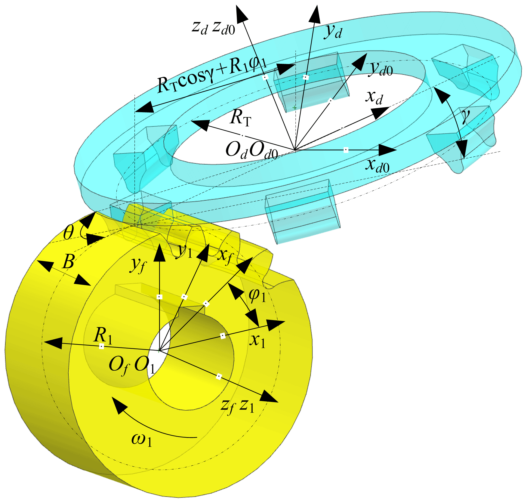
According to the meshing theory and forming principle of modified tooth surface (Litvin, 2008), the modified tooth surface mathematical model of the VH-CATT cylindrical gear can be written as follows:
where u0 is the distance between the parabolic vertex position and the pitch line of the unmodified straight blade; a is the parabolic coefficient, where the outer blade is positive and the inner blade is negative; α is the pressure angle; n is the order of the parabolic function, which is an integer (such as 1, 2, and 3) and corresponds to the second-, fourth- and sixth-order parabolic modified tooth surface equations, respectively; and m is the gear modulus.
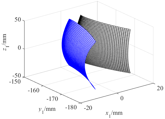
According to the modified tooth surface equation, the modified tooth surface mathematical model is established by MATLAB and the three-dimensional model of the VH-CATT cylindrical gear is established by UG. Figure 2 is the modified tooth surface mathematical model. Figure 3 is the modified gear 3D model of the VH-CATT cylindrical gear. The important parameters are as follows: tooth number is z= 41, tooth width B= 80 mm, pressure angle α= 20°, modulus m= 8 mm, tooth line radius RT= 200 mm, parabolic coefficient a= 0, cutterhead inclination angle γ= 5°, and the order of the parabolic function n= 1.

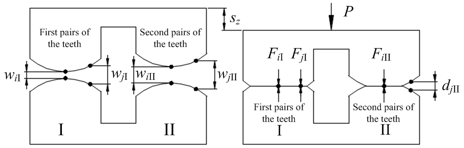
To get the common normal displacement of the load-bearing contact gear pair, a loaded tooth contact analysis model of the VH-CATT cylindrical gear is established, as shown in Fig. 4. The schematic diagram of the loaded tooth contact analysis model of the VH-CATT cylindrical gear is the cross-sectional expansion diagram of the tooth surface along the long axis of the contact ellipse.
In Fig. 4, i is the number of the instantaneous contact ellipse centre, j is a discrete point number along the long axis of the ellipse, w is the initial gap of a discrete point on the tooth surface before contact that can be calculated by the tooth contact analysis model, d is the actual remaining gap of a discrete point on the tooth surface after loading deformation, sz is the common normal displacement of the load-bearing contact gear pair, P is the load, I is the first pairs of the teeth, and II is the second pairs of the teeth.
According to Fang (1998), the deformation compatibility equation at discrete point j can be expressed as
where if dj=0, Fj>0, or if dj>0, Fj=0, and fjk is the flexibility coefficient of the VH-CATT cylindrical gear pair.
Considering multi-tooth contact and n discrete points, the total deformation compatibility equation is written in matrix form as follows:
where S is the contact point flexibility matrix, F is the contact point load matrix, w is the tooth surface gap matrix before deformation, e is the unit matrix, d is the remaining gap matrix after deformation, and Q is the number of contact teeth.
Based on the conditions of the deformation coordination, force balance, and non-embedding, the following mathematical model is established to describe the equilibrium state of the tooth contact under load:
where P is the tooth surface load; j is the discrete point number, ; ; nI and nII are the unit normal vectors of the first and second pairs of the teeth; and diI and diII are the matrixes composed of the rotation radius of the discrete points on the contact line.
In Eq. (4), S, w, T, and n are the known parameters. P, sz and d are the parameters to be solved. The ratio of the single-gear-pair tooth surface load to gear-pair system load is the load distribution coefficient, as shown in Eq. (5).
The meshing stiffness of the gear system is the ratio of the normal load and the normal displacement of the VH-CATT cylindrical gear pair, shown as Eq. (6). The normal load of the tooth surface and the normal displacement of the gear pair can be calculated by LTCA. Therefore, Eq. (6) is called the VH-CATT cylindrical gear meshing stiffness model.
Due to the deformation compatibility conditions, LTCA results show that the normal deformation of several pairs of teeth meshing at the same time is consistent. In addition, because the flexibility coefficients of the different contact points are different, the tooth surface loads of the different meshing gears are different at the same time. The single-tooth meshing stiffness can be obtained by multiplying the comprehensive meshing stiffness by the load distribution coefficient of the corresponding point, as shown in Eq. (7).
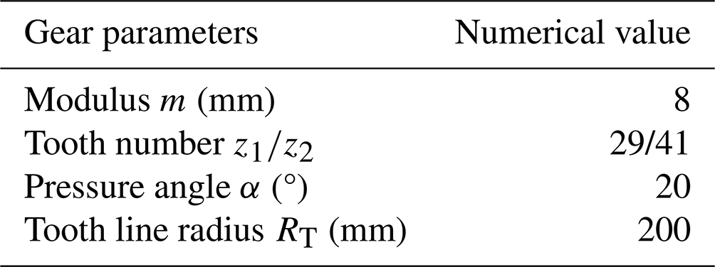
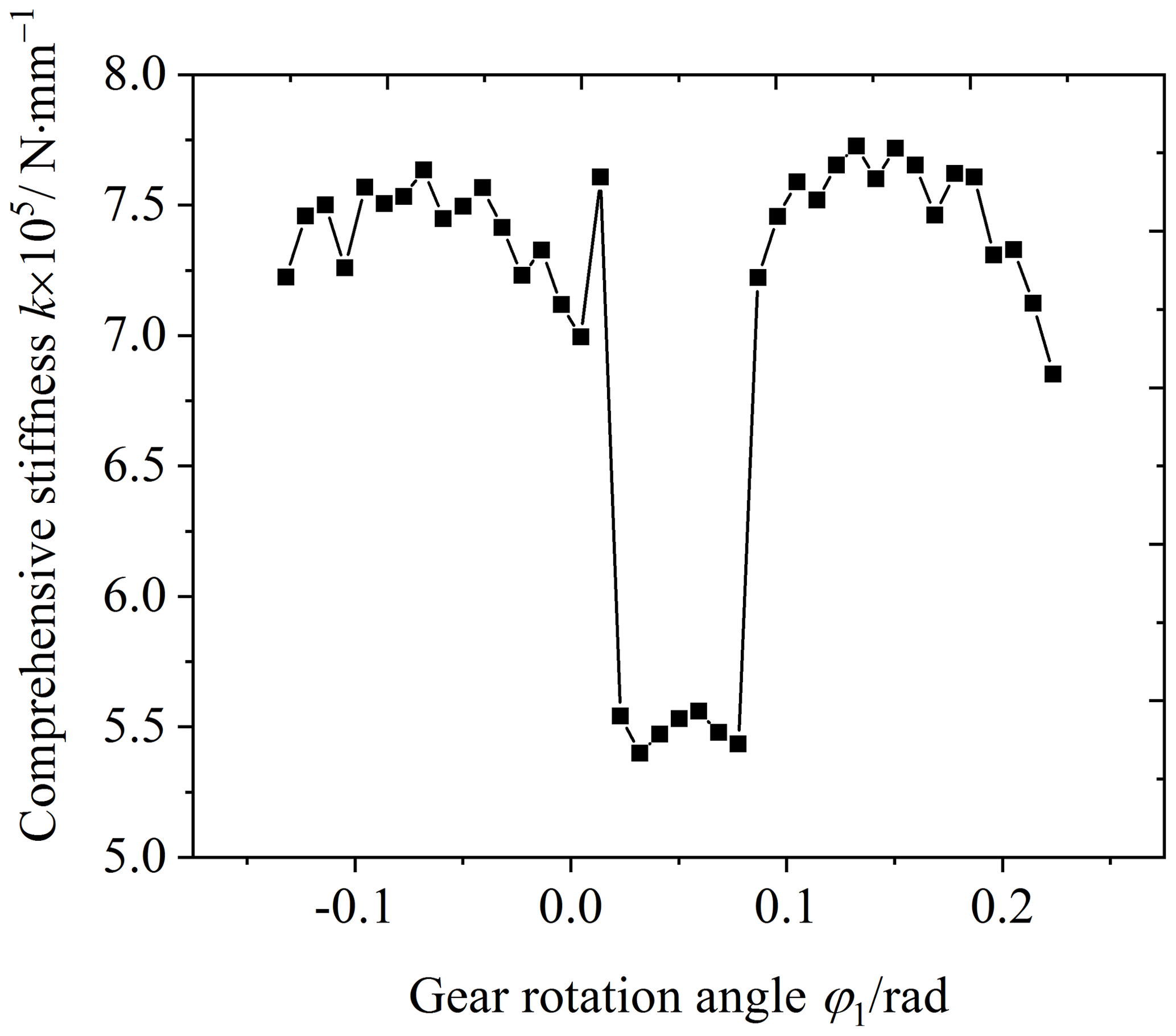
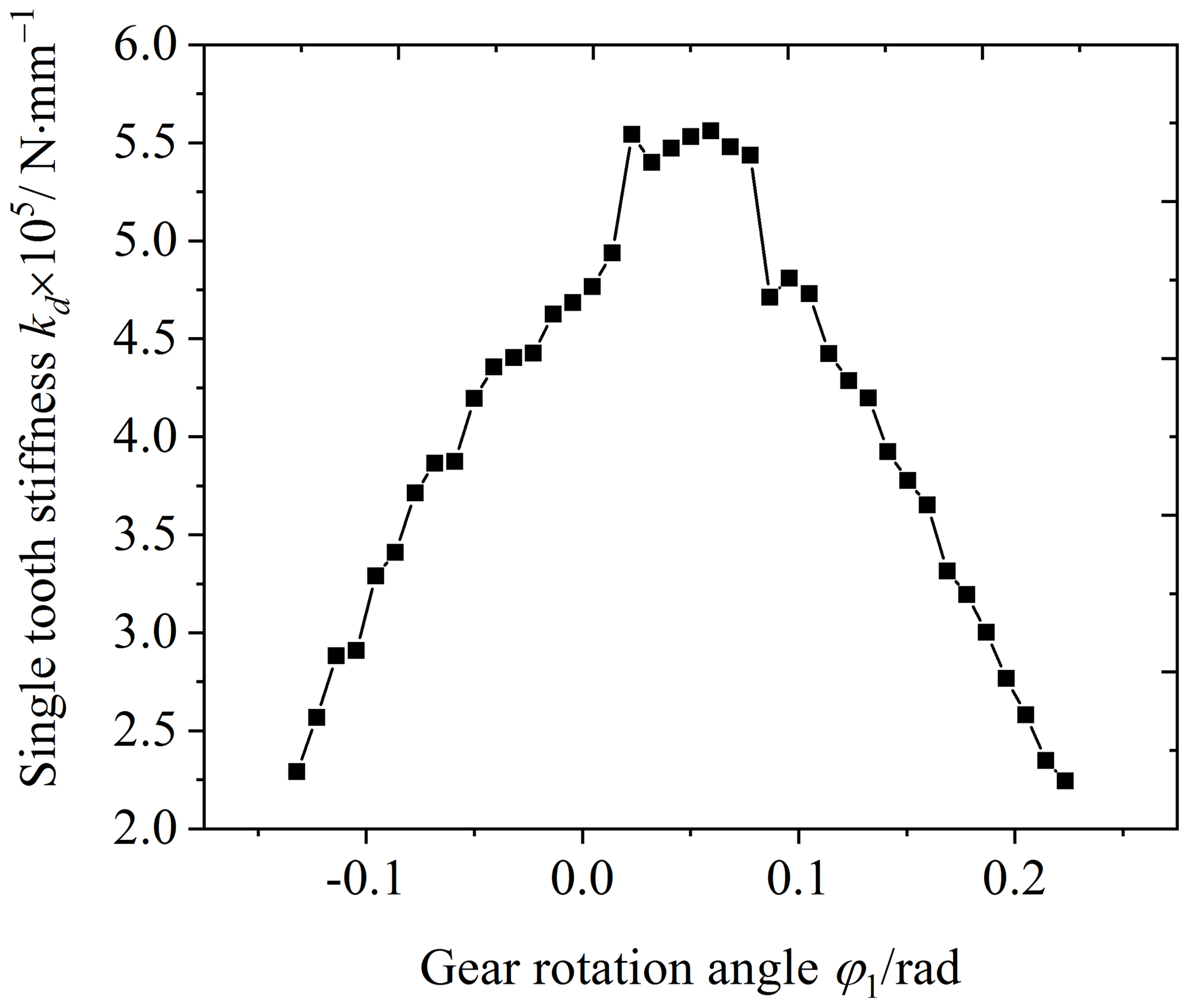
According to the main parameters of the gear structure for the meshing stiffness analysis, shown in Table 1, the gear comprehensive stiffness and single-tooth stiffness were calculated by the LTCA method, as shown in Figs. 5 and 6. The comprehensive stiffness of the VH-CATT cylindrical gear-pair changes periodically, and there is a sudden change in the comprehensive stiffness. A pair of teeth is engaged in some meshing areas, and two pairs of teeth are engaged in some areas. The change trend of the single-tooth stiffness is small at both ends and large in the middle, which is consistent with the theoretical analysis of gear tooth meshing stiffness.
Table 1Main parameters of gear structure for meshing stiffness analysis.
Because the finite-element calculation has the characteristics of the accuracy and high efficiency, it is gradually becoming widely used in the dynamic calculation of the gear system, and it can also be used to calculate the meshing stiffness of the VH-CATT cylindrical gear system. Therefore, this method can be used to verify the LTCA stiffness calculation method. The calculation steps of the meshing stiffness based on the finite-element method are as follows: import the 3D model into ABAQUS, calculate the deformation of the gear contact area, extract the normal load of the meshing contact area, and calculate the meshing stiffness based on the definition formula of the meshing stiffness, as shown in Eq. (8).
where kn is the meshing stiffness of the single-tooth obtained by the finite-element method, Fn is the normal load of the tooth surface obtained by the finite-element method, and un is the comprehensive elastic deformation of the gear teeth obtained by the finite-element method.
The comprehensive deformation of the single tooth includes the tooth surface contact elastic deformation, uh; the deformation displacement, ub, caused by the tooth bending; and the gear support system deformation, uf. Because the deformation problem of the gear support system is extremely complex, only the tooth surface contact deformation, uh, and the bending deformation, ub, are considered when the comprehensive deformation is calculated. Therefore, the comprehensive deformation of the gear system is
when the gear system is a multi-tooth contact and the gear teeth are in parallel. Therefore, the comprehensive meshing stiffness of the gear system is as follows:
where p is the number of teeth meshing at the same time.
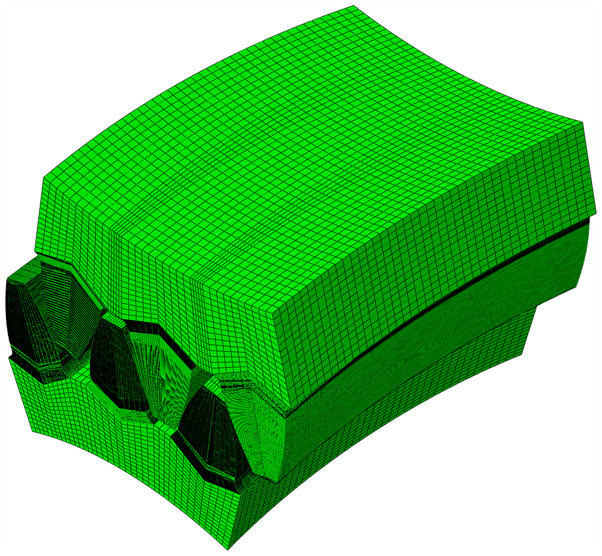
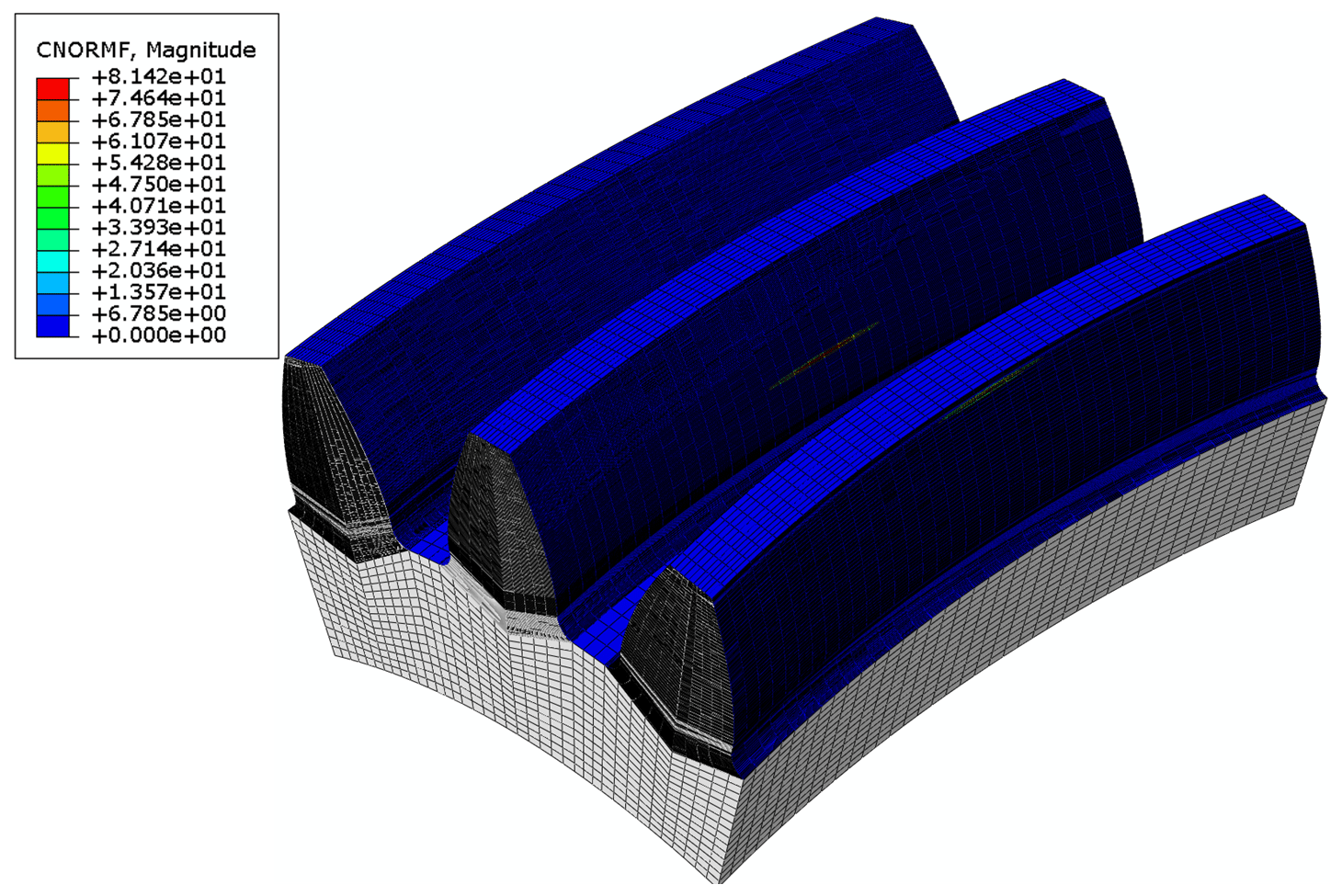
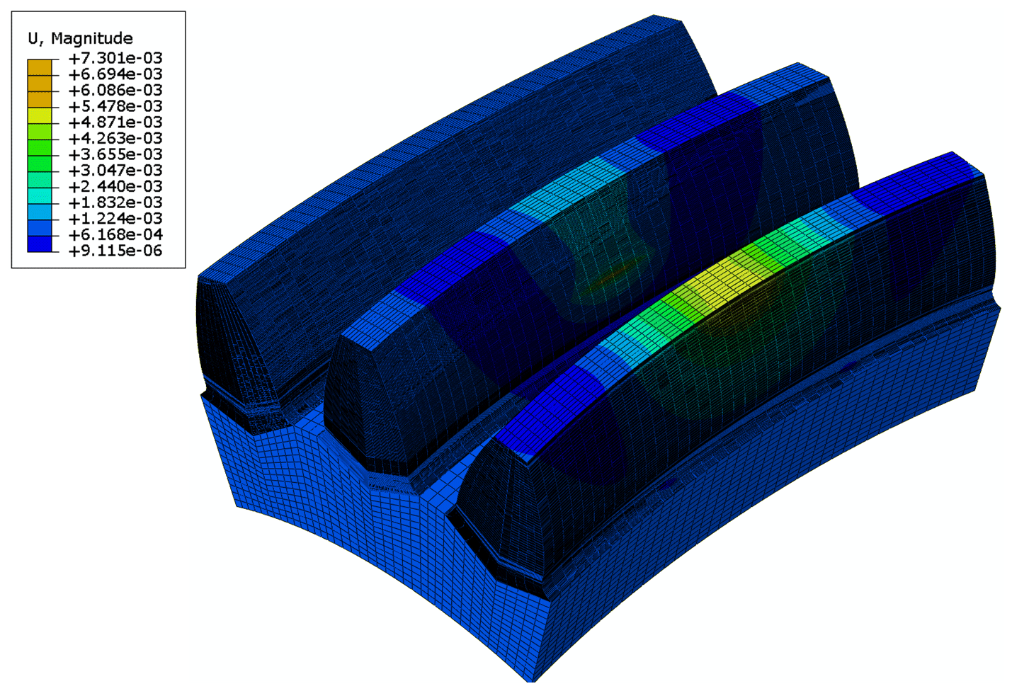
Figure 7 is the meshing stiffness finite-element model. The torque of the driven wheel is equal to 1000 N m. The gear density is equal to T mm−3, the comprehensive elastic modulus is equal to 210 GPa, and Poisson's ratio is equal to 0.3. Figure 8 is the contact force cloud map of the driving gear tooth surface in a certain position. It can be seen from the figure that the contact area of the gear pair is a slender ellipse and that the contact force at the centre of the contact ellipse is the largest. Figure 9 is the contact tooth surface deformation cloud map. The contact form of the VH-CATT cylindrical gear pair is pointing contact. According to the Hertz contact theory, the maximum deformation of the VH-CATT cylindrical gear pair occurs at the theoretical contact point of the VH-CATT cylindrical gear pair, and the deformation at the contact point is the comprehensive elastic deformation of the VH-CATT cylindrical gear.
To calculate the normal load and deformation of the tooth surface from meshing in to meshing out, the driving gear is rotated by 1° each time, and the driven gear is rotated by a certain angle according to the transmission ratio. The deformation and normal load are calculated and extracted at each position. The finite-element calculation results show that the overall trend of the comprehensive deformation of the driving gear from meshing in to meshing out gradually decreases, which is consistent with the theoretical trend. However, the deformation of the gear teeth suddenly increases due to the reduction in the number of load-bearing teeth in the single-tooth meshing area. The change trend of the driven gear comprehensive deformation is the same as that of the driving gear. The comprehensive deformation of the gear pair is small at both ends and large in the middle, which is also consistent with the theoretical change trend.
Figure 10 shows the comparison between the results of the LTCA calculation and the finite-element calculation. It can be seen from the figure that there is a certain error in the calculation results of the two methods. The average meshing stiffness error in the VH-CATT cylindrical gear pair in the meshing-in double-tooth meshing area is 9.18 %, the average meshing stiffness error in the VH-CATT cylindrical gear pair in the single-tooth meshing area is 15.95 %, and the average meshing stiffness error in the VH-CATT cylindrical gear pair in the meshing-out double-tooth meshing area is 9.61 %. The main reasons for the meshing stiffness error are meshing quality, small rotation displacement of the driving gear, constraint conditions, deformation, and contact post-processing. However, overall, the meshing stiffness variation law of the VH-CATT cylindrical gear pair calculated by the two methods is consistent. The meshing stiffness of the VH-CATT cylindrical gear pair in the double-tooth meshing area is large, and the meshing stiffness of the gear pair in the single-tooth meshing area is small. The meshing stiffness of the VH-CATT cylindrical gear pair in the single–double-tooth meshing alternating area has obvious mutation properties.
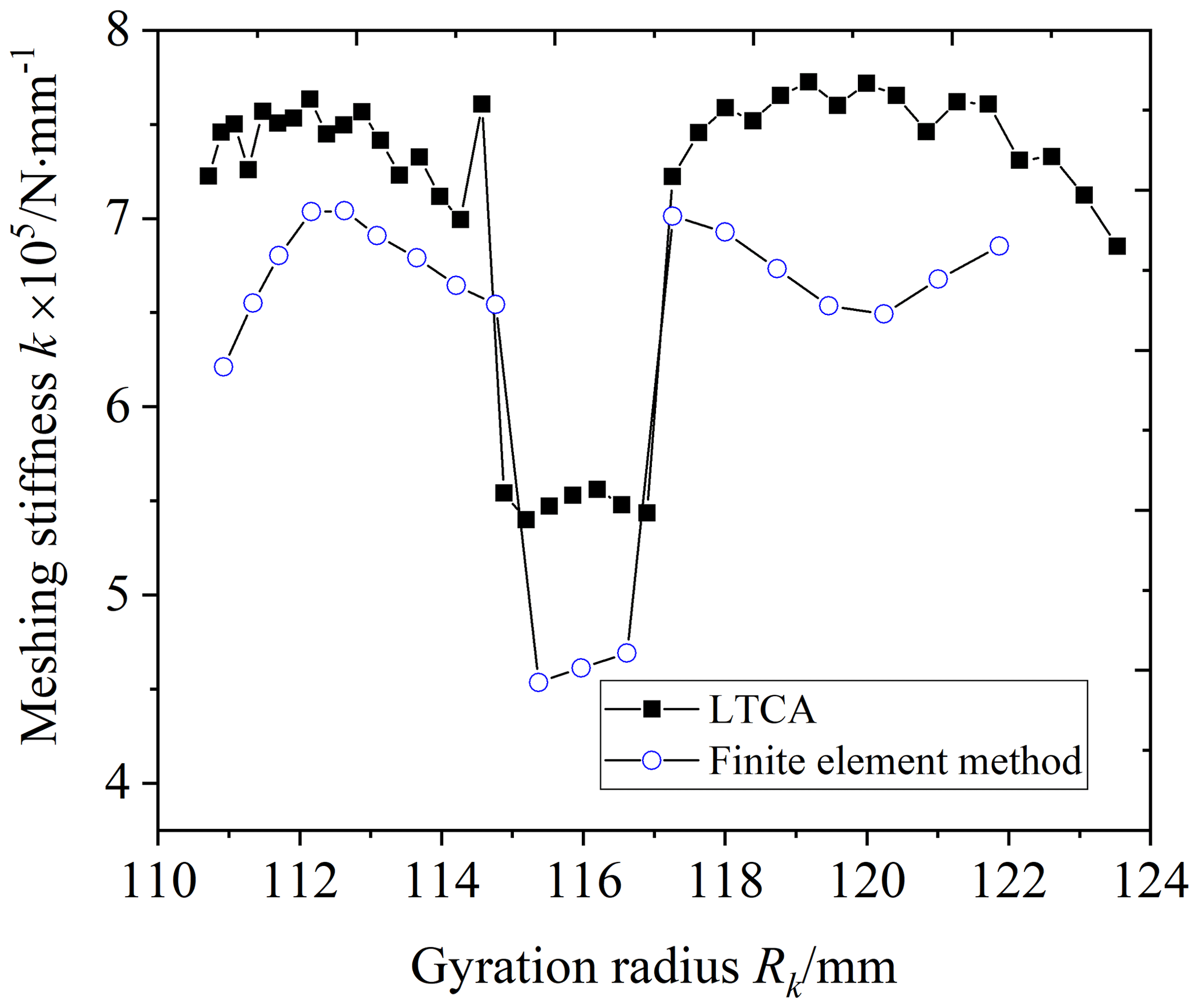
Figure 10Comparison between meshing stiffness calculation results between LTCA and finite-element method.
5.1 Influence of load on the VH-CATT cylindrical gear stiffness
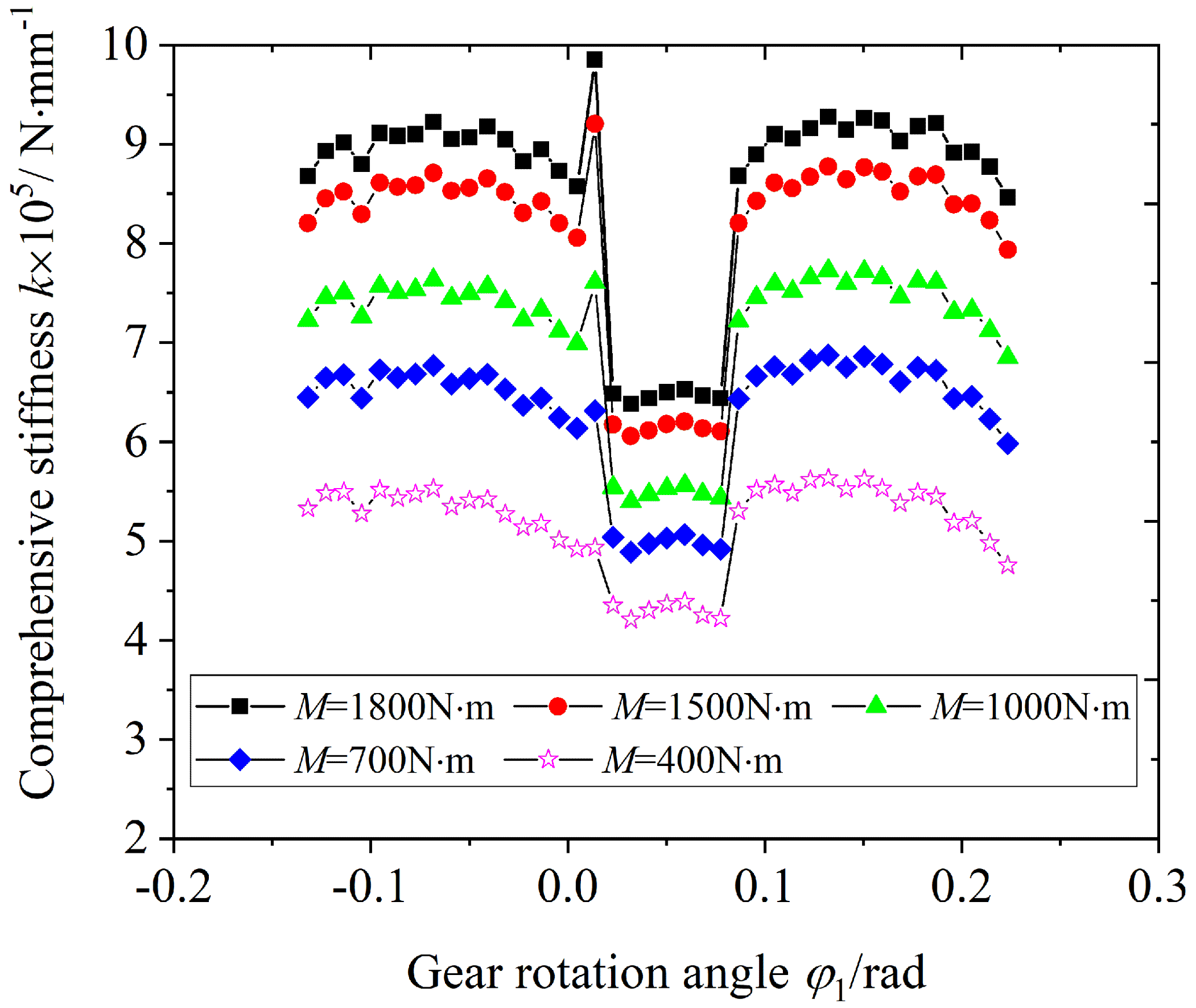
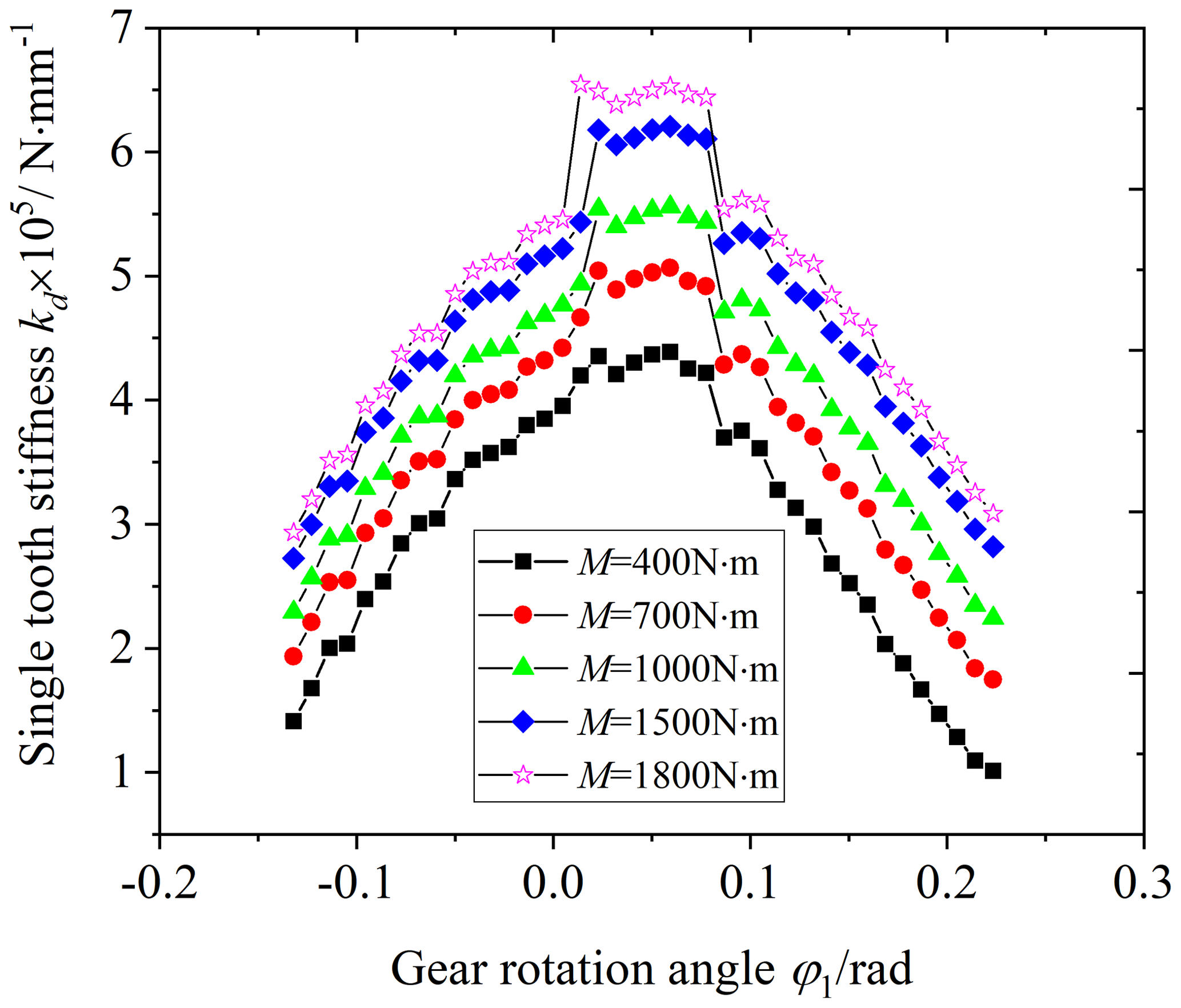
Figure 11 is the influence of the load on the comprehensive stiffness of the VH-CATT cylindrical gear pair, and Fig. 12 is the influence of the load on the single-tooth stiffness. The load is equal to 400, 700, 1000, 1500, and 1800 N m.
Observing Figs. 11 and 12, the comprehensive stiffness and single-tooth stiffness increase with an increase in the load. The reason is that the external load of the gear pair increases, the contact ellipse area of the tooth surface increases, and the deformation of the VH-CATT cylindrical gear system decreases. At the same time, it can also be seen from the figures that the mutation of the comprehensive stiffness in the single–double-tooth alternating area also increases. The reasons are that the load increases and the deformation difference in the VH-CATT cylindrical gear system before and after the single–double-tooth alternating increases.
5.2 Influence of cutter inclination angle on the VH-CATT cylindrical gear stiffness
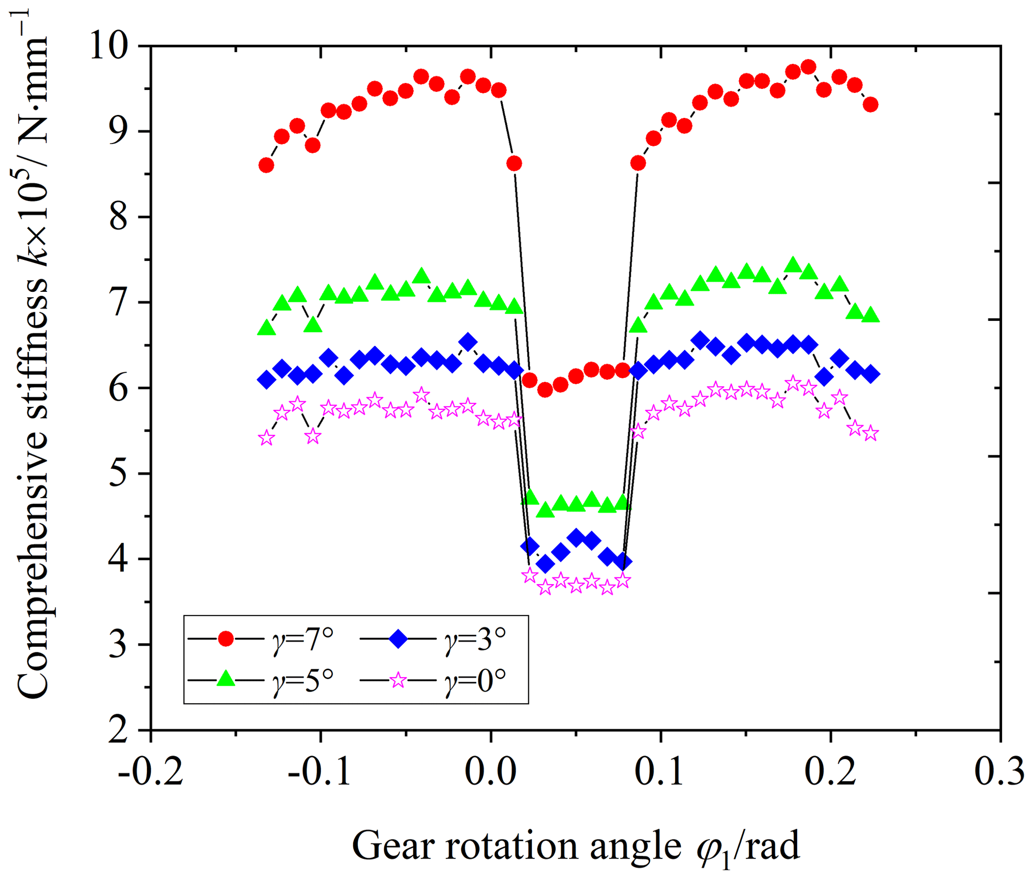
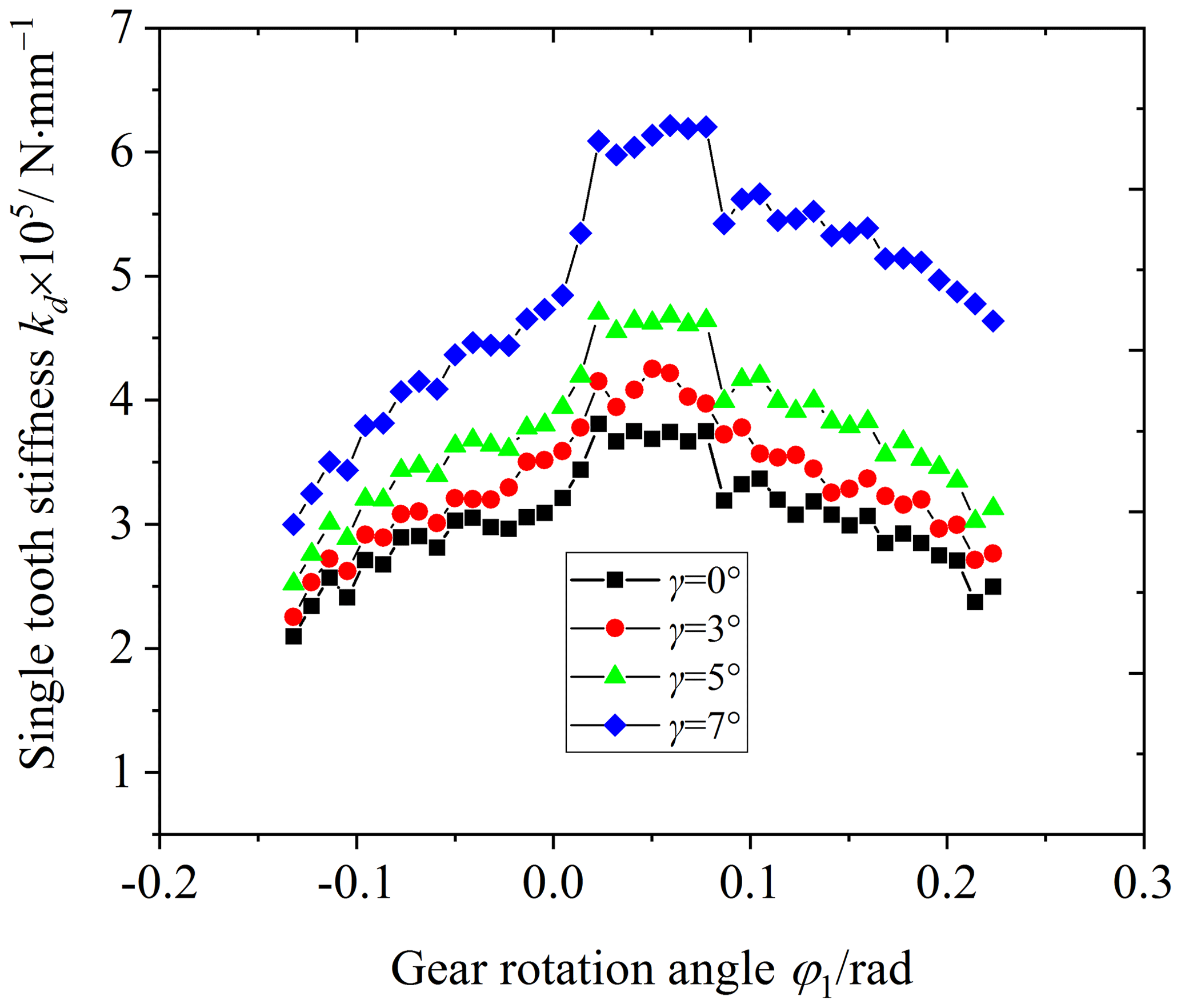
Figure 13 is the influence of the cutter inclination angle on the comprehensive stiffness of the VH-CATT cylindrical gear pair, and Fig. 14 is the influence of the cutter inclination angle on the single-tooth stiffness of the VH-CATT cylindrical gear pair. The cutter inclination angle is equal to 0, 3, 5, and 7°.
Observing Figs. 13 and 14, the comprehensive stiffness and single-tooth stiffness of the VH-CATT cylindrical gear pair increase with an increase in the cutter inclination angle. The larger the cutter inclination angle, the larger the stiffness increase amplitude of the VH-CATT cylindrical gear. For example, the average increase amplitude of the comprehensive stiffness in the meshing-in double-tooth meshing area is equal to 8.70 %, 20.57 %, and 45.97 %. The average increase amplitude of the comprehensive stiffness in the single-tooth meshing area is equal to 9.89 %, 24.45 %, and 64.35 %. The average increase amplitude of the comprehensive stiffness in the meshing-out double-tooth meshing area is equal to 10.79 %, 25.27 %, and 76.86 %. The reasons are that the cutter inclination angle increases and that the elliptical contact area of the tooth surface increases; the larger the cutter inclination angle, the greater the increase in the elliptical area and the smaller the system comprehensive deformation under load. Namely, the stiffness of the VH-CATT cylindrical gear pair becomes greater.
5.3 Influence of parabolic coefficient on the VH-CATT cylindrical gear stiffness
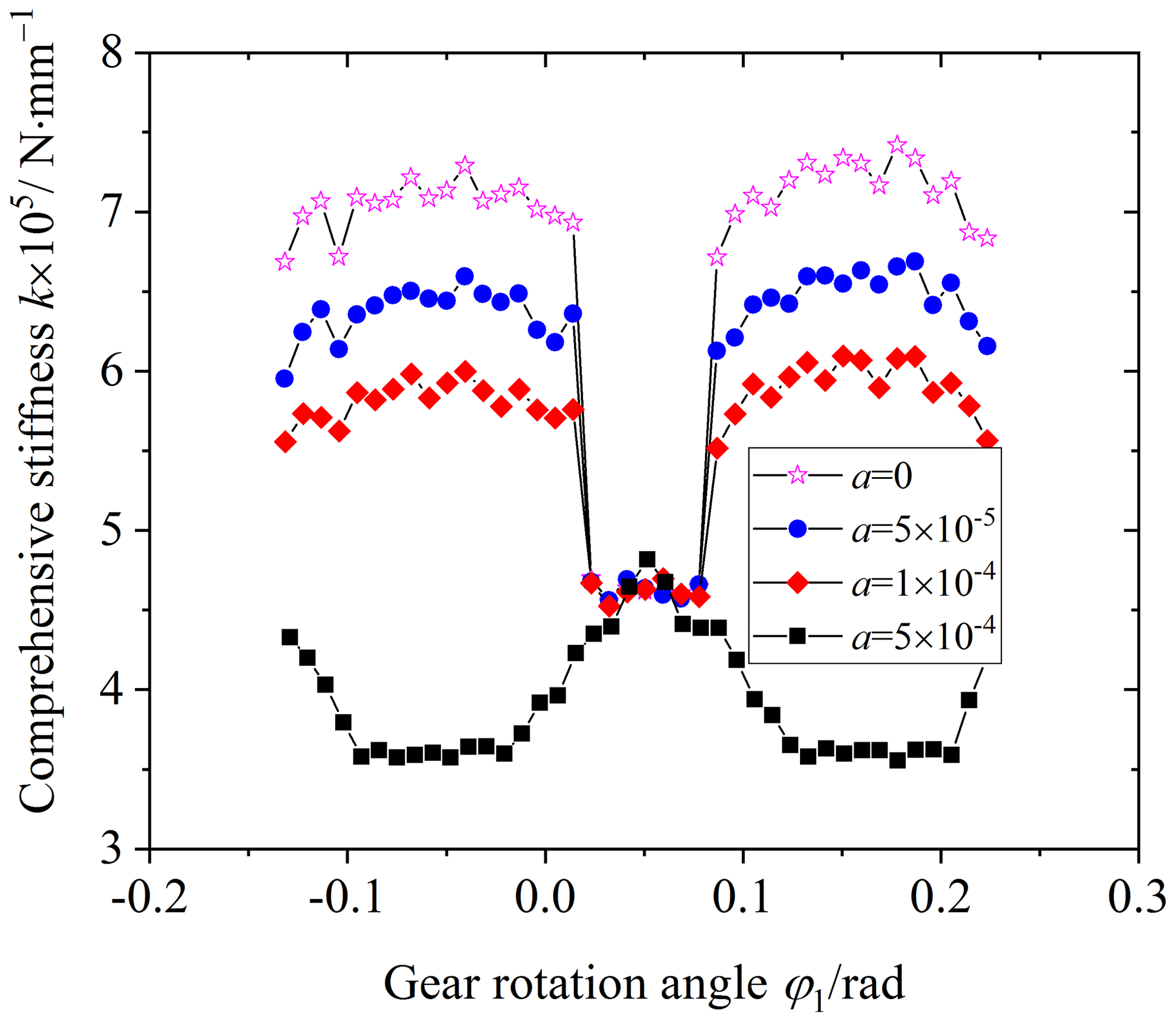
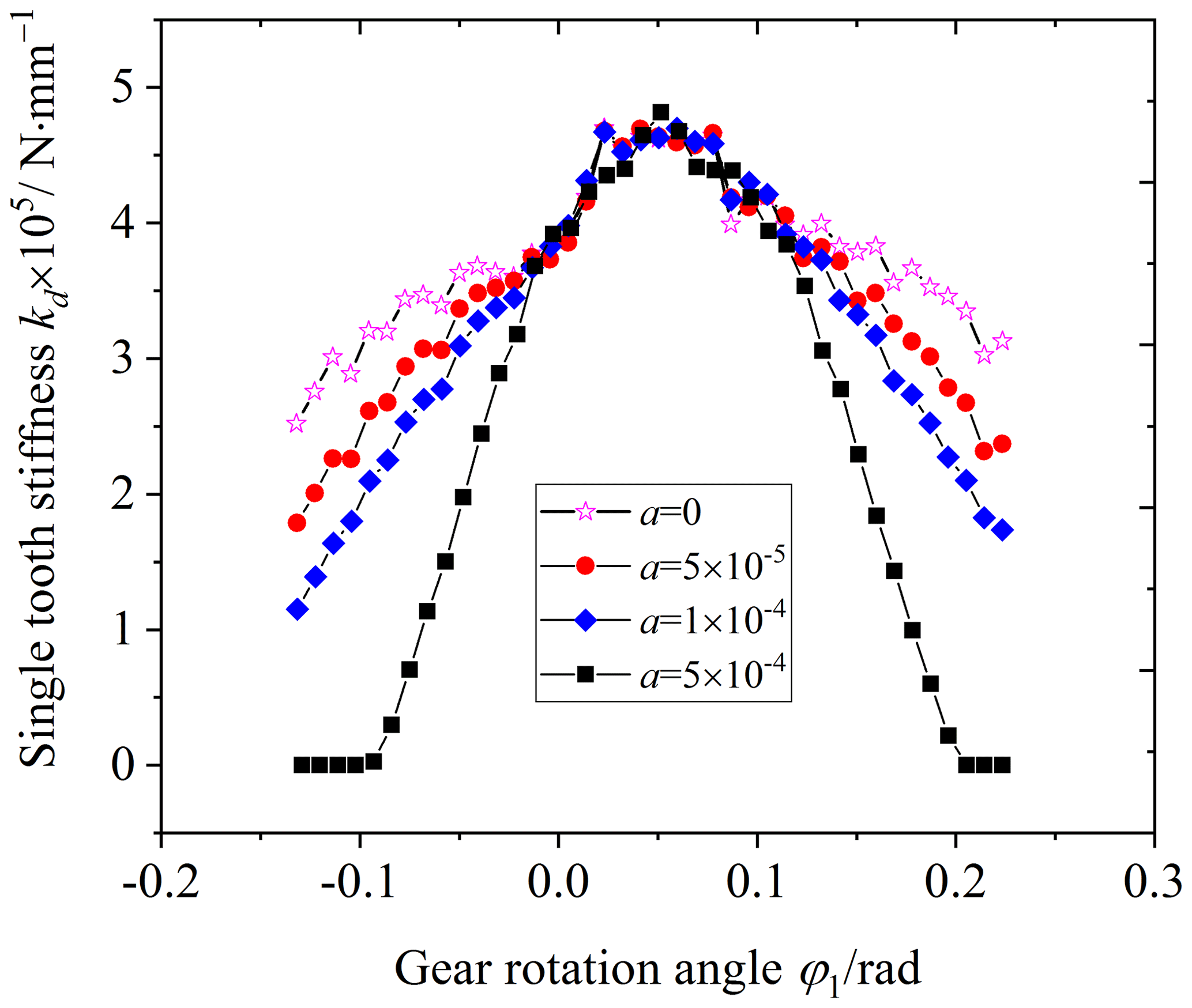
Figure 15 is the influence of the parabolic coefficient on the comprehensive stiffness of the VH-CATT cylindrical gear pair, and Fig. 16 is the influence of the parabolic coefficient on the single-tooth stiffness of the VH-CATT cylindrical gear pair. The parabolic coefficient is equal to 0, , , and .
Observing Figs. 15 and 16, the comprehensive stiffness and single-tooth stiffness of the VH-CATT cylindrical gear pair in the double-tooth meshing area decrease with an increase in the parabolic coefficient. When the parabolic coefficient is greater than , the change rule of the comprehensive stiffness of the VH-CATT cylindrical gear pair changes, but the influence is small in the single-tooth meshing area. The reason is that the parabolic forming blade removes a certain material of the VH-CATT cylindrical gear surface. After modification, the tooth thickness decreases, and the tooth surface gap increases. The farther away from the vertex position of the parabolic blade, the smaller the tooth thickness and the larger the surface gap. When the tooth surface clearance increases, the VH-CATT cylindrical gear system needs a greater deformation under load, and the latter pair of tooth surfaces will come in contact. And the larger the gap, the greater the deformation required. Therefore, the meshing stiffness of the VH-CATT cylindrical gear pair in the double-tooth meshing area decreases. When the parabolic coefficient is equal to in particular, due to the large gap, the phenomenon of premature exit and delayed entry of the VH-CATT cylindrical gear pair occurs. Therefore, the single-tooth meshing stiffness is equal to 0 at the meshing entry or exit time, and the change law of the comprehensive stiffness of the VH-CATT cylindrical gear pair also changes. And the tooth surface gap at the parabolic vertex of the blade is the same as that of the unmodified tooth surface gap. Therefore, the comprehensive stiffness and single-tooth meshing stiffness of the VH-CATT cylindrical gear pair in the single-tooth meshing area are basically unchanged.
5.4 Influence of parabolic vertex position on the VH-CATT cylindrical gear stiffness
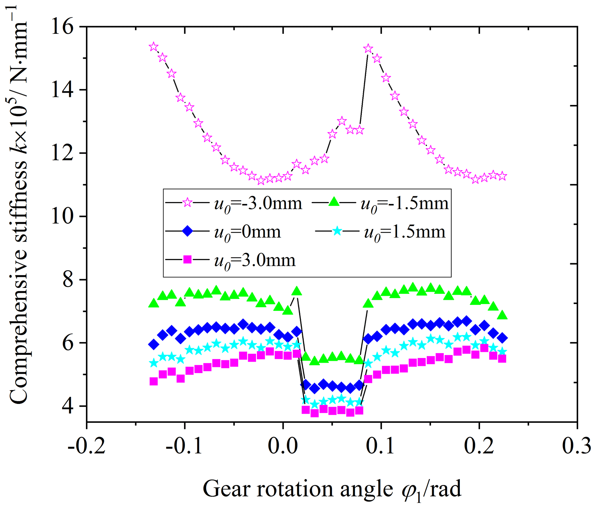
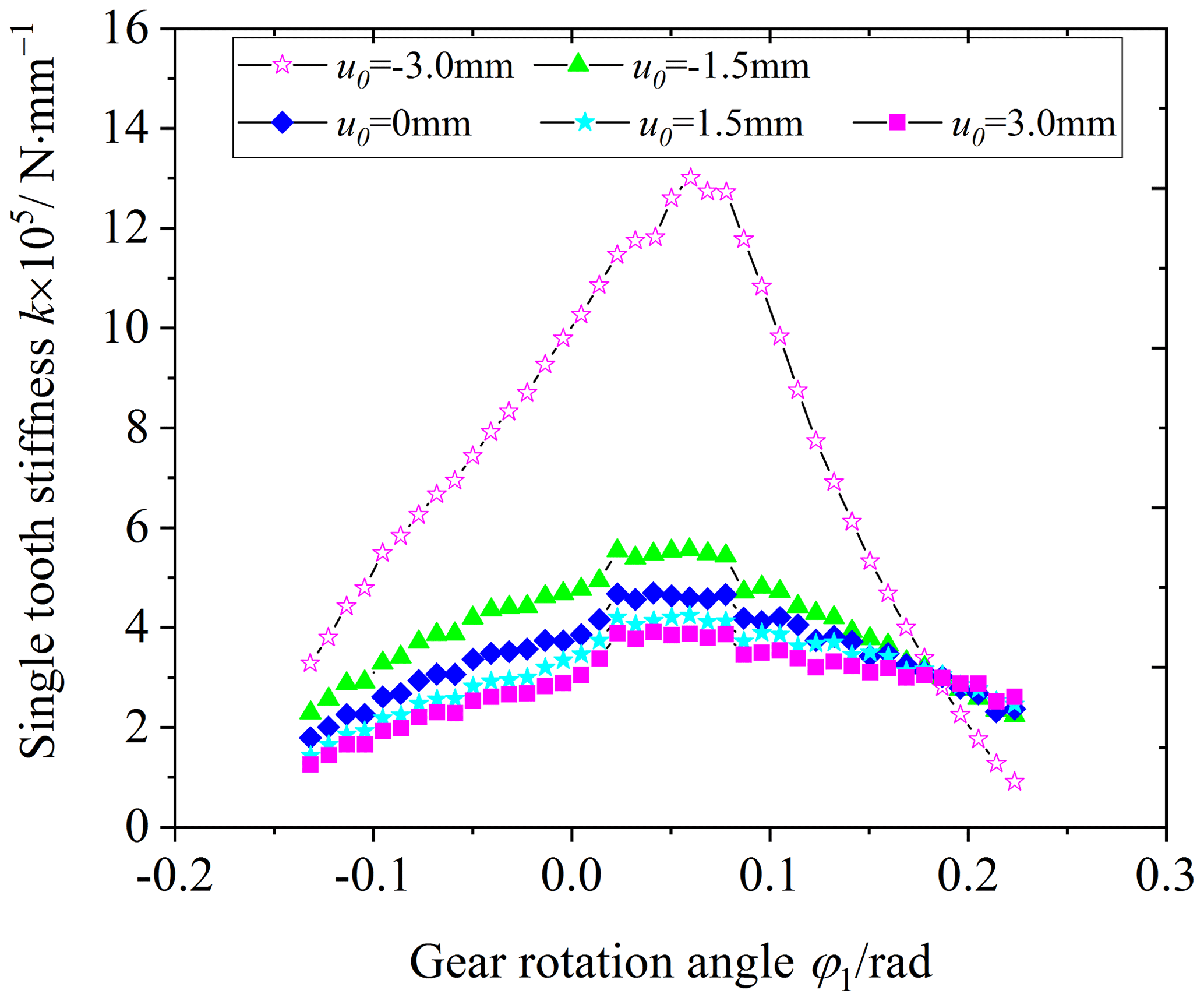
Figure 17 is the influence of the parabolic vertex position of the blade on the comprehensive stiffness of the VH-CATT cylindrical gear pair, and Fig. 18 is the influence of the parabolic vertex position of the blade on the single-tooth stiffness of the VH-CATT cylindrical gear pair. The parabolic vertex position u0 is equal to −3, −1.5, 0, 1.5, and 3 mm.
Observing Figs. 17 and 18, the comprehensive stiffness and single-tooth stiffness of the VH-CATT cylindrical gear pair increase with a decrease in the blade parabolic vertex position value. When the parabolic vertex position u0 is equal to −3 mm in particular, most of the contact tooth surfaces are almost in full-tooth-width contact based on the tooth surface load distribution, as shown in Fig. 19. Therefore, the deformation and meshing stiffness of the VH-CATT cylindrical gear system are very complicated. In addition, the reason why the comprehensive stiffness and single-tooth meshing stiffness of the VH-CATT cylindrical gear pair increase with the decrease in the parabolic vertex position is that the smaller the parabolic vertex position, the larger the tooth surface contact area, the smaller the load in the unit area, and the smaller the comprehensive deformation of the VH-CATT cylindrical gear pair.

This paper discusses the meshing stiffness characteristics of the modified variable hyperbolic circular-arc-tooth-trace cylindrical gears. Firstly, the tooth surface equation of the modified VH-CATT cylindrical gear was deduced based on the meshing theory, and the modified tooth surface mathematical model and 3D model were developed. Next, the load tooth contact analysis mathematical model of the VH-CATT cylindrical gear was developed. The calculation formulas of the meshing stiffness for the VH-CATT cylindrical gear based on the LTCA were then given, and the finite-element calculation was used to verify the LTCA stiffness calculation method. Finally, the influence of the load and modification parameters on the VH-CATT cylindrical gear stiffness was investigated. The main conclusions can be expressed as follows:
- 1.
The stiffness calculation method of the VH-CATT cylindrical gear based on LTCA is proposed and verified by the finite-element calculation. The research shows that the stiffness calculation method of the VH-CATT cylindrical gear based on LTCA is correct.
- 2.
The meshing stiffness of the VH-CATT cylindrical gear in the double-tooth meshing area is large, and the meshing stiffness of the VH-CATT cylindrical gear in the single-tooth meshing area is small. The meshing stiffness of the VH-CATT cylindrical gear in the single–double-tooth meshing alternating area has obvious mutation properties.
- 3.
The comprehensive stiffness and single-tooth stiffness of the VH-CATT cylindrical gear increase with an increase in the load and cutter inclination angle. The comprehensive stiffness and single-tooth stiffness of the VH-CATT cylindrical gear in the double-tooth meshing area generally decrease with an increase in the parabolic coefficient, but the influence is small in the single-tooth meshing area. The comprehensive stiffness and single-tooth stiffness of the VH-CATT cylindrical gear increase with a decrease in the blade parabolic vertex position value.
- 4.
In the present paper, the meshing stiffness characteristics of the modified variable hyperbolic circular-arc-tooth-trace cylindrical gears is discussed, but the influence of the load and modification parameters on the nonlinear dynamics is not carried out. Therefore, the main work will focus on the vibration and noise reduction in the VH-CATT cylindrical gear in the future.
All the code and data used in this paper can be obtained upon request to the corresponding author.
DM and ZY conceived the presented idea. DM and YL established an overall paper research framework and the model. DM and BJ conducted data calculation for the entire paper. All the authors discussed the results and contributed to the final paper.
The contact author has declared that none of the authors has any competing interests.
Publisher's note: Copernicus Publications remains neutral with regard to jurisdictional claims made in the text, published maps, institutional affiliations, or any other geographical representation in this paper. While Copernicus Publications makes every effort to include appropriate place names, the final responsibility lies with the authors.
The authors would like to thank anonymous reviewers for their valuable comments and suggestions that enabled us to revise the paper.
This research has been supported by the Guizhou Provincial Basic Research Program (Natural Science) (grant no. Qiankehejichu-ZK[2021]yiban273).
This paper was edited by Daniel Condurache and reviewed by two anonymous referees.
Cai, J., Zheng, Q., Lan, Q., Wang, L., Yang, S., and Sheng, R.: Time-varying meshing stiffness and dynamic parameter model of spiral bevel gears with different surface roughness, Appl. Sci.-Basel, 14, 1533, https://doi.org/10.3390/app14041533, 2024.
Chen, Y. C. and Lo, C. C.: Contact stress and transmission errors under load of a modified curvilinear gear set based on finite element analysis, P. I. Mech. Eng. C-J. Mec., 229, 191–204, https://doi.org/10.1177/0954406214532907, 2015.
Fang, Z.: Model and approach for loaded tooth contact analysis (LTCA) of gear drives, J. Mech. Trans., 2, 2–4+17+53, 1998 (in Chinese).
Fuentes, A., Ruiz-Orzaez, R., and Gonzalez-Perez, I.: Computerized design, simulation of meshing, and finite element analysis of two types of geometry of curvilinear cylindrical gears, Comput. Method. Appl. M., 272, 321–339, https://doi.org/10.1016/j.cma.2013.12.017, 2014.
Fuentes-Aznar, A., Ruiz-Orzaez, R., and Gonzalez Perez, I.: Comparison of spur, helical and curvilinear gear drives by means of stress and tooth contact analyses, Meccanica, 52, 1721–1738, https://doi.org/10.1007/s11012-016-0515-y, 2017
Guo, R., Wei, Y., Liu, Y., Li, D., Yang, D., and Zhao, G.: Analytical solution to contact characteristics for a variable hyperbolic circular-arc-tooth-trace cylindrical gear, Mech. Sci., 12, 923–932, https://doi.org/10.5194/ms-12-923-2021, 2021.
Litvin, F.: Gear geometry and applied theory, Shanghai Science and Technology Press, China Shanghai, ISBN: 9787532394203, 2008.
Liu, Y. and Ma, D.: Surface modification and tooth contact analysis of variable hyperbolic circular-arc-tooth-trace cylindrical gears, Mech. Sci., 13, 909–920, https://doi.org/10.5194/ms-13-909-2022, 2022.
Luo, P., Wu, Y., Liang, S., and Hou, L.: TEHL analysis of VH-CATT cylindrical gear transmission in elliptical contact considering time-varying parameters, Adv. Mech. Eng., 14, 905–919, https://doi.org/10.1177/16878132221081615, 2022.
Ma, D., Wei, Y., and Ye, Z.: Mesh contact impact of circular arc tooth traces cylindrical gears, J. Vib. Shock, 37, 123–131, 2018 (in Chinese).
Ma, D., Ye, Z., and Yang, H.: Tooth surface reconstruction and tooth profile geometric analysis of circular arc tooth trace cylindrical gears, T. Famena, 43, 29–44, https://doi.org/10.21278/TOF.43103, 2019.
Ma, D., Liu, Y., and Ye, Z.: Analysis of the tooth surface contact area of a circular arc tooth trace cylindrical gear under load, T. Famena, 45, 79–94, https://doi.org/10.21278/TOF.451018220, 2021a.
Ma, D., Liu, Y., and Ye, Z.: Meshing contact impact properties of circular arc tooth trace cylindrical gear based on rotating knife dish milling process, Math. Probl. Eng., 2021, 8819818, https://doi.org/10.1155/2021/8819818, 2021b.
Ma, D., Liu, Y., Ye, Z., Li, D., and Wu, Y.: Influence of cutter errors on forming accurate variable hyperbolic circular arc tooth trace cylindrical gears, T. Famena, 47, 13–31, https://doi.org/10.21278/TOF.474044222, 2023a.
Ma, D., Liu, Y., and Ye, Z.: Modification design and load tooth contact analysis of a cylindrical gear with variable hyperbolic circular arc tooth trace, J. Vib. Shock, 42, 170–179, 2023b (in Chinese).
Marafona, J., Marques, P, Martins, R., and Seabra, J.: Mesh stiffness models for cylindrical gears: A detailed review, Mech. Mach. Theory, 166, 104472, https://doi.org/10.1016/j.mechmachtheory.2021.104472, 2021.
Meng, Z., Pang, X., Hao, G., Jin, Y., Li, J., and Fan, F.: A novel analytical model for evaluating the time-varying meshing stiffness of helical gears under irregular pitting failure, Arch. Appl. Mech., 93, 3775–3795, https://doi.org/10.1007/s00419-023-02460-x, 2023.
Mo, S., Hu, Q., Liu, M., Wang, L., Bao, H., Cen, G., and Huang, Y.: Research on time-varying meshing stiffness of wind turbine gearbox considering tooth surface wear, P. I. Mech. Eng. J-J. Eng., 237, 1583–1602, https://doi.org/10.1177/13506501231172258, 2023.
Ni, G., Liu, Z., Song, C., Liu, S., Dong, Y., and Cao, Y.: Geometric parameter design and contact characteristics of beveloid gear and involute cylindrical gear transmission with crossed axes, J. Mech. Sci. Technol., 38, 815–825, https://doi.org/10.1007/s12206-024-0128-7, 2024.
Pedrero, J., Pleguezuelos, M., and Sánchez, M.: Analytical model for meshing stiffness, load sharing, and transmission error for helical gears with profile modification, Mech. Mach. Theory, 185, 105340, https://doi.org/10.1016/j.mechmachtheory.2023.105340, 2023.
Wang, F., Fang, Z., and Li, S.: Nonlinear Dynamic analysis of helical gear considering meshing impact, Appl. Mech. Mater., 201–202, 135–138, https://doi.org/10.4028/www.scientific.net/amm.201-202.135, 2012.
Wang, G., Luo, Q., and Zou, S.: Time-varying meshing stiffness calculation of an internal gear pair with small tooth number difference by considering the multi-tooth contact problem, J. Mech. Sci. Technol., 35, 4073–4083, https://doi.org/10.1007/s12206-021-0819-2, 2021.
Wei, Y., Guo, R., and Liu, Y.: Analytical calculation of the tooth surface contact stress of cylindrical gear with variable hyperbolic circular arc tooth trace, Symmetry, 12, 1318, https://doi.org/10.3390/SYM12081318, 2020.
Wei, Y., Li, Z., Liu, Y., Guo, R., Yang, D., Luo, L., and Chen, Z.: Geometric contact characteristics and sensitivity analysis of variable hyperbolic circular-arc-tooth-trace cylindrical gear with error theory considered, Journal of Northwestern Polytechnical University, 40, 679–689, https://doi.org/10.1051/jnwpu/20224030679, 2022a (in Chinese).
Wei, Y., Yang, D., Guo, R., Ren, Z., Li, Z., and Luo, L.: Integrated wear prediction model for cylindrical gear with variable hyperbolic circular arc tooth trace under mixed elastohydrodynamic lubrication. J. Mech. Sci. Technol., 36, 4053–4065, https://doi.org/10.1007/s12206-022-0726-1, 2022b.
Wu, Y., Luo, P., Bai, Q., Liang, S., Fan, Q., and Hou, L.: Modelling and analyzing of loaded meshing characteristics of cylindrical gear transmission with curvilinear-shaped teeth, Meccanica, 58, 1555–1580, https://doi.org/10.1007/s11012-023-01690-1, 2023.
Xia, H., Meng, F., Zhang, X., Wang, J., and Jin, Y.: Nonlinear dynamics analysis of gear system considering time-varying meshing stiffness and backlash with fractal characteristics, Nonlinear Dynam., 111, 14851–14877, https://doi.org/10.1007/s11071-023-08649-7, 2023.
Xie, C. and Yu, W.: Gear dynamic modelling based on the concept of dynamic mesh stiffness: theoretical study and experimental verification, J. Mech. Sci. Technol., 36, 4953–4965, https://doi.org/10.1007/s12206-022-0909-9, 2022.
Yu, X., Sun, Y., Li, H., and Wu, S.: Nonlinear characteristics of gear pair considering fractal surface dynamic contact as internal excitation, Int. J. Nonlin. Mech., 2022, 143, 104027, https://doi.org/10.1016/j.ijnonlinmec.2022.104027, 2022.
Zhang, X., Xie, Y., and Tan, X.: Design, meshing characteristics and stress analysis of cylindrical gears with Curvilinear tooth profile, T. Famena, 40, 27–44, 2016.
Zhou, C., Dong, X., Wang, H., and Liu, Z.: Time-varying mesh stiffness model of a modified gear–rack drive with tooth friction and wear, J. Braz. Soc. Mech. Sci., 44, 213, https://doi.org/10.1007/s40430-022-03517-8, 2022a.
Zhou, C., Xing, M., and Hu, B.: A mesh stiffness model with the asperity contact for spur gear in mixed elastohydrodynamic lubrication, J. Braz. Soc. Mech. Sci., 44, 466, https://doi.org/10.1007/s40430-022-03748-9, 2022b.
- Abstract
- Introduction
- Modified tooth surface mathematical model
- Load tooth contact analysis mathematical model
- VH-CATT cylindrical gear meshing stiffness calculation and FEM verification
- Influences of load and modification parameters on the VH-CATT cylindrical gear stiffness
- Conclusion
- Code and data availability
- Author contributions
- Competing interests
- Disclaimer
- Acknowledgements
- Financial support
- Review statement
- References