the Creative Commons Attribution 4.0 License.
the Creative Commons Attribution 4.0 License.
 | 08 May 2024
Study on the contact performance of the variable hyperbolic circular arc tooth trace cylindrical gear with installation errors
Dengqiu Ma
Bing Jiang
Lingli Bao
Zhenhuan Ye
Yongping Liu
Installation errors are important factor for the contact performance of the variable hyperbolic circular arc tooth trace (VH-CATT) cylindrical gear; the study of the relationship between installation errors and contact performances is beneficial for gear vibration and noise reduction. Firstly, based on the meshing theory, the tooth surface equation and contact ellipse of the VH-CATT cylindrical gear were deduced, and the tooth surface imprinting experiment was realized. Next, the tooth contact analysis model of the VH-CATT cylindrical gear was developed to investigate the influence of the installation errors on the elliptical contact area. Then, the calculation formulas of the tooth surface gap and contact point flexibility matrix were carried out to develop the load tooth contact analysis model of the VH-CATT cylindrical gear. Finally, the influence of the installation errors on the load distribution was investigated. Research shows that the elliptical contact area of the VH-CATT cylindrical gear is a line contact within a certain range and is located in the middle section of the tooth width. The elliptical contact area of the VH-CATT cylindrical gear increases or decreases rapidly when meshing in and out, and all the installation errors have a certain influence on the elliptical contact area, except for the center distance error. The single-tooth meshing area with the installation errors is greater than that of the ideal gear pair. The load distribution area with the installation errors deviates from the middle section, except for the center distance error. The installation rotation errors around the x and y axis have a certain influence on the maximum load of the single-tooth meshing area. The research results provide a basis for improving the bearing capacity of the VH-CATT cylindrical gear and optimizing the design.
- Article
(9023 KB) - Full-text XML
- BibTeX
- EndNote


Error is an important factor in the research of mechanical equipment development, mechanism performance analysis and robot engineering, and many studies have been carried out in this regard (Wu et al., 2013, 2022; Ye et al., 2023). Gear transmission meshing performances are one of the most important research topics in gear transmission, and the installation error is one of the important factors of the meshing performance of the gear transmission system (Liu et al., 2023). The installation errors will directly lead to the deviation of the gear meshing position, which is one of the excitation sources of the gear meshing impact, vibration and noise (Li et al., 2022).
The variable hyperbolic circular arc tooth trace (VH-CATT) cylindrical gear is a kind of cylindrical gear, but it is different from the spur gear and helical gear. The tooth direction line of the VH-CATT cylindrical gear is an arc line, the tooth profile of middle cross section is involute, the tooth profile of the other sections is hyperbolic and the projection of the tooth surface contact area on the common section of the contact point is an ellipse (Ma et al., 2019, 2021a). Because the application of the VH-CATT cylindrical gear has great potential and advantages, the VH-CATT cylindrical gear has rich achievements in terms of the meshing principle, contact performances, manufacturing and so on, especially the meshing performance.
The influence of the different installation errors and different design parameters on the geometric contact characteristics and sensitivity of the gear pair is analyzed (Wei et al., 2022a). Guo et al. (2021) established an analytical solution to investigate the influence of different parameters on the induced normal curvature and contact ellipse of the VH-CATT cylindrical gear. Liu and Ma (2022) proposed a tooth surface modification design method based on the parabolic forming blade and cutter inclination to improve the bearing capacity of the VH-CATT cylindrical gear. Wei et al. (2020) proposed a computing formula of the maximum contact stress of the VH-CATT cylindrical gear according to Hertz formula, which provided a reference for the contact stress calculation of the VH-CATT cylindrical gear. Wei et al. (2022b) also proposed an integrated wear prediction model through taking into account flash contact temperature and surface roughness of the VH-CATT cylindrical gears in mixed elastohydrodynamic lubrication. Based on the three-dimensional model, the contact stress and bending stress of the VH-CATT cylindrical gear are studied by finite element calculation and compared with the contact characteristics of the straight gear and helical gear by Fuentes-Aznar et al. (2017), Fuentes et al. (2014), Chen et al. (2015) and Zhang et al. (2016). Luo et al. (2022) established a mathematical model for tooth contact analysis (TCA) and loaded tooth contact analysis (LTCA) to calculate the most time-varying parameters in a meshing period and developed a thermo-elastohydrodynamic lubrication (TEHL) model of an elliptical contact of this gear transmission further. Chen et al. (2017) established a 12-DOF bending-torsion-shaft multi-factor coupling dynamical model of the VH-CATT cylindrical gear based on the theory of concentrated parameter to obtain the gear vibration rule. Ma et al. (2018, 2021b) proposed the meshing contact impact hypothesis of the VH-CATT cylindrical gear based on the contact dynamics theory and gear transmission physical model; the gear mesh contact impact model was set up further to obtain the VH-CATT cylindrical gear's meshing contact impact properties. And Ma et al. (2023) established a load-bearing contact nonlinear mathematical programming model to obtain the load-bearing meshing characteristics; the influences of the modifying parameters on load distribution and load transmission error of the modified tooth surface were analyzed.
The research potential of the VH-CATT cylindrical gear is very rich. However, there are still some restricting factors in the industrial application of the VH-CATT cylindrical gear. For example, the influence of installation errors on the transmission quality of gear system is not very clear, and so the design of the VH-CATT cylindrical gear vibration and noise reduction tooth surface cannot be carried out effectively.
Therefore, a study on the contact performance of the variable hyperbolic circular arc tooth trace cylindrical gear with installation errors was proposed. The tooth surface equation and contact ellipse of the VH-CATT cylindrical gear were deduced based on the gear machining development principle and the tooth surface imprinting experiment was realized. And the tooth contact analysis (TCA) model of the VH-CATT cylindrical gear was developed, and the influence of installation errors on elliptical contact area was analyzed. Then, the calculation formulas of the tooth surface gap and contact point flexibility matrix were carried out to develop load tooth contact analysis model of the VH-CATT cylindrical gear. The influence of the installation errors on the load distribution was investigated further. The research content provides a technical basis for improving the bearing capacity of the VH-CATT cylindrical gear and optimizing the design.
2.1 Mathematical model of tooth surface
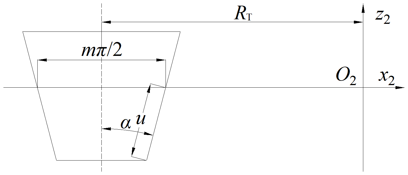
To develop the tooth surface mathematical model of the VH-CATT cylindrical gear, the tooth-surface-forming coordinate system of double-edged milling with a large cutter head is developed, as shown in Fig. 1. Figure 2 is the schematic diagram of the cutter edge geometry and parameters. O1x1y1z1 is the dynamic coordinate system of the gear blank, and it follows the movement of the gear blank. O2x2y2z2 is the dynamic coordinate system of the cutter, and it follows the movement of the cutter. O3x3y3z3 is the static coordinate system of the cutter. Ofxfyfzf is the static coordinate system of the gear blank. O0x0y0z0 is the intermediate auxiliary coordinate system. In Figs. 1 and 2, the parameters are specifically explained as follows: m is the gear module, RT is the tooth line radius, R1 is the pitch circle radius, B is the gear width, α is the pressure angle, ω is the angular velocity of the cutter, ω1 is the angular velocity of the gear blank, φ1 is the involute angle, θ is the spreading angle of the cutter and u is the distance from any point on the blade profile along the blade to the x axis. The value of u is positive in the positive half axis of the z axis and negative in the negative half axis of the z axis.
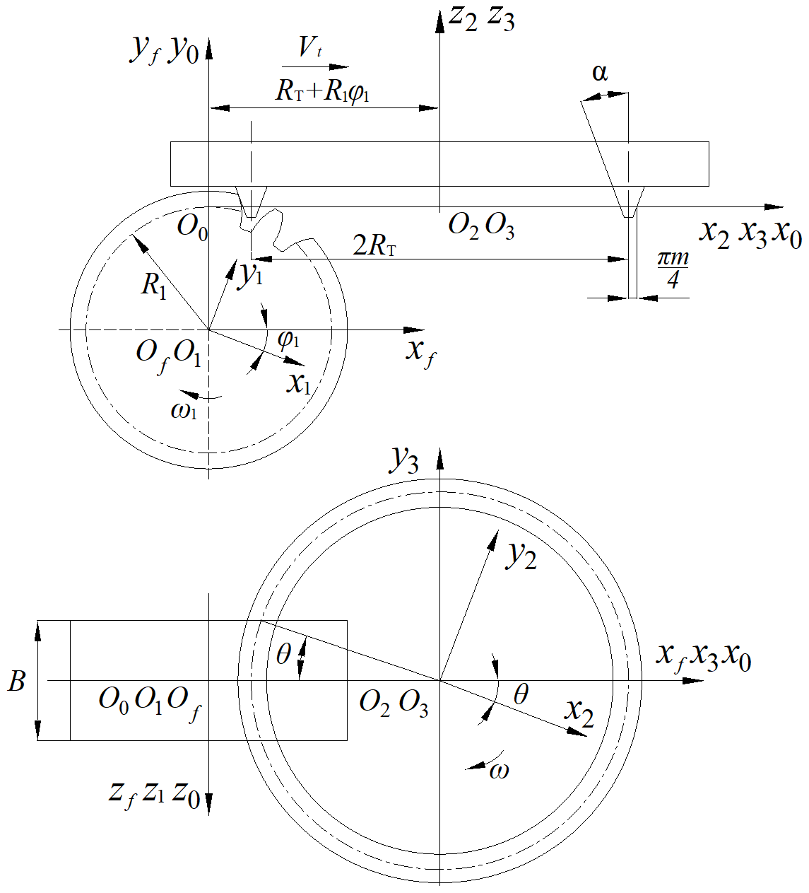
Figure 1Tooth-surface-forming coordinate system of double-edged milling with a large cutter head.
According to Figs. 1 and 2, the cutter expression in the coordinate system O3x3y3z3 can be written as
According to the gear meshing principle (Litvin, 2008), the cutter and the tooth surface have the same position vector at the meshing point. The relative velocity between the cutter and the tooth surface at the meshing point is perpendicular to the normal line of the meshing point . Therefore,
According to Eq. (1), the normal vector can be written as
According to Zhao et al. (2016), the relative speed at the meshing point of the tooth surface is Eq. (4).
where
In addition, according to Zhao et al. (2016) and Fig. 1, the transformation matrix M13 from O3x3y3z3 to O1x1y1z1 is Eq. (9):
According to the gear geometry (Zhao et al., 2020), the expression of the contact point between the cutter and the tooth surface in the coordinate system O1x1y1z1 is the tooth surface equation of the VH-CATT cylindrical gear. The expression can be written as Eq. (10).
2.2 Tooth surface contact ellipse
Ma et al. (2021a) show that the contact form of the VH-CATT cylindrical gear processed by the double-edged milling with a large cutter head is the point contact. Due to the elastic deformation of the tooth surface under load, the tooth surface contact will expand from a point to an elliptical contact area. If the contact section is projected onto the tangent plane of the instantaneous contact point, the contact area generally appears as an ellipse, as shown in Fig. 3. And the center of the instantaneous contact ellipse overlaps with the theoretical contact point. At the same time, Litvin (2008) pointed out that the elastic deformation of the tooth surface depends on the gear load, and the elastic deformation of the tooth surface δ is 0.00632 mm under a light load. In fact, the contact trace is a series of contact ellipses in the entire process of the gear meshing.
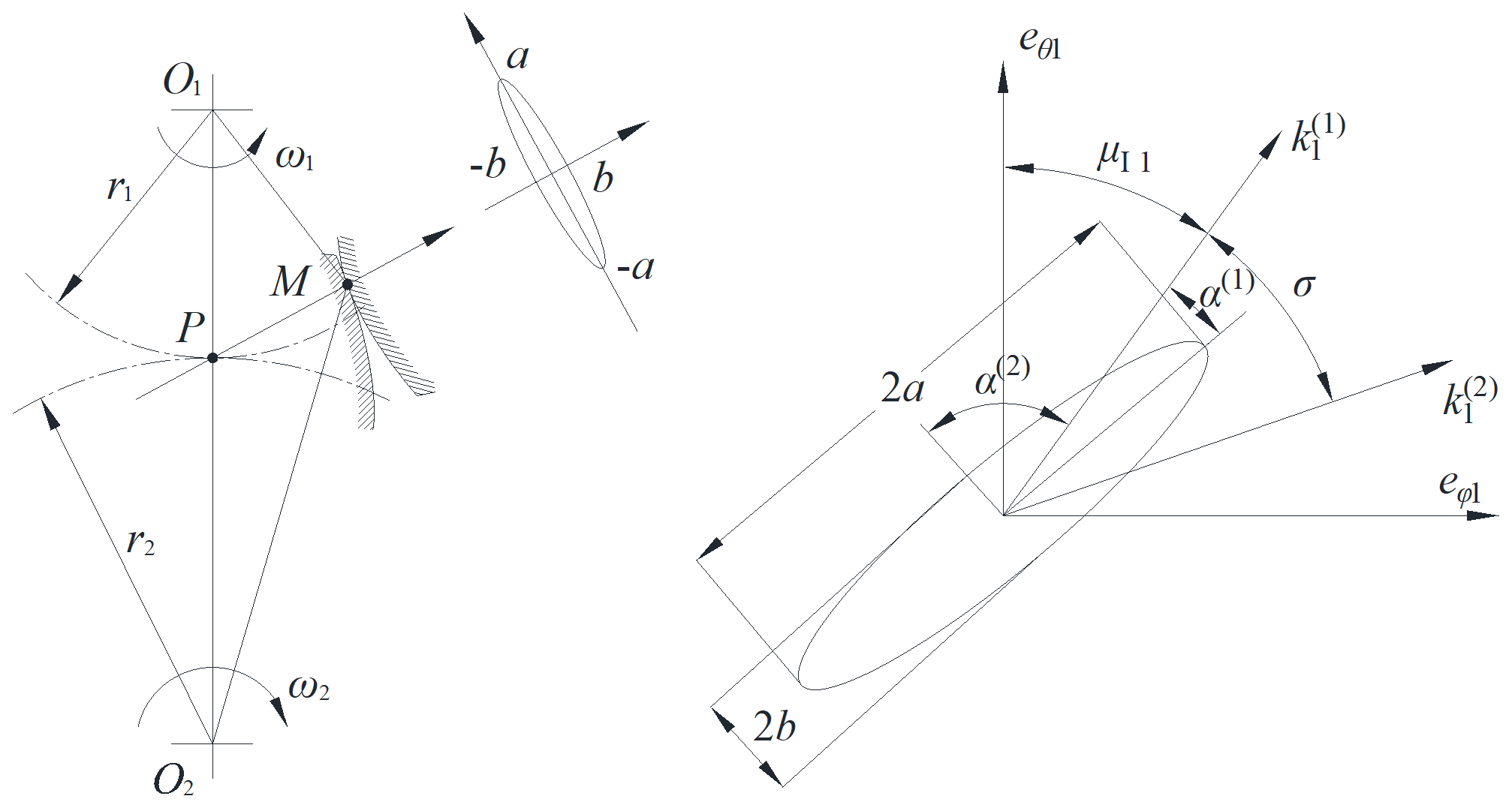
The contact ellipse equation of the VH-CATT cylindrical gear can be written as Eq. (11) (Ma et al., 2021a).
The contact ellipse's long axis a and short axis b can be calculated based on Eqs. (11) to (17).
The contact ellipse area can be represented as
Figure 4 is the experimental result of the tooth surface mark, where Fig. 4a is the gear pair before the experiment, and the tooth surface is coated with vermilion, and Fig. 4b is the real tooth surface contact area of the gear pair. The important parameters are as follows: tooth number z1= 21 and z2= 29, tooth width B= 80 mm, pressure angle α= 20°, modulus m= 8 mm, tooth line radius RT= 200 mm. According to the experimental result of the tooth surface mark, the contact area of the gear pair will be extended to a line contact within a certain tooth width range, and the gear contact area is in the middle area of the tooth width. The length of the contact line is twice that of the contact ellipse long axis.
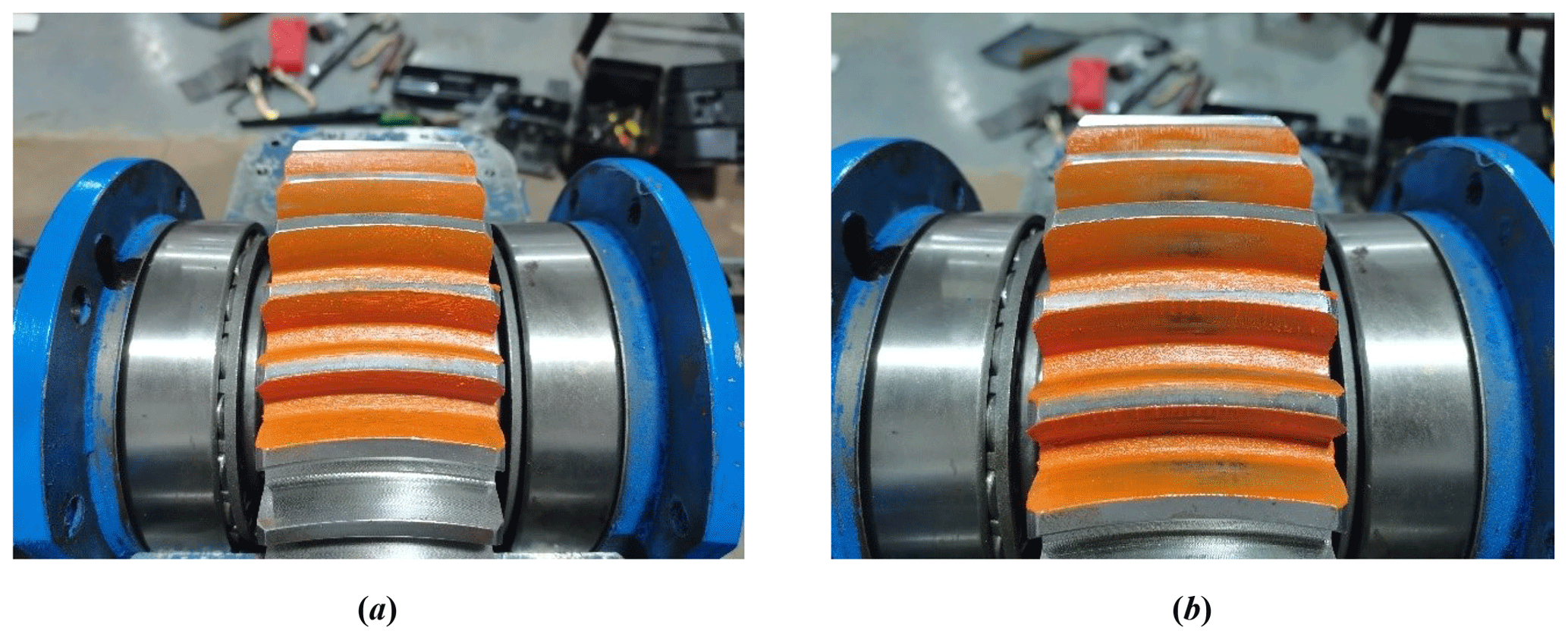
Figure 4Experimental result of the tooth surface mark. (a) Gear pair coated with vermilion. (b) Real tooth surface contact area of gear pair.
Figure 5 shows the gear pair meshing transmission coordinate system with installation errors. ΣI is the driving gear tooth surface, ΣII is the driven gear tooth surface, M is the instantaneous contact point, nc is the common normal line of the instantaneous contact point, ψ1 is the driving gear meshing angle, ψ2 is the driven gear meshing angle, ΔE is the center distance error, ΔA is the axial installation error, γx is the error of the driven gear installation rotation around the x axis and γy is the error of the driven gear installation rotation around the y axis. O1X1Y1Z1 is the follower coordinate system of the driving gear, OgXgYgZg is the fixed coordinate system of the driving gear, OdaXdaYdaZda is the center distance error coordinate system, OpfXpfYpfZpf is the axial installation error coordinate system, OγxXγxYγxZγx is the error coordinate system of the driven gear installation rotation around the x axis and OγyXγyYγyZγy is the error coordinate system of the driven gear installation rotation around the y axis, it is also a fixed coordinate system of the driving gear, O2X2Y2Z2 is the follower coordinate system of the driven gear.

The driving gear tooth surface r1 and unit normal vector of the driving gear tooth surface n1 can be represented in the coordinate system OgXgYgZg by the following equations:
where
The driven gear tooth surface r2 and unit normal vector of the driven gear tooth surface n2 can be represented in the coordinate system OgXgYgZg by the following equations:
where
The driving gear tooth surface and the driven gear tooth surface are regarded as being in continuous tangency and are represented in the coordinate system OgXgYgZg.
Equations (27) and (28) express the tooth contact analysis model. The solutions of the tooth contact analysis model are θ1(ψ1), φ1(ψ1), θ2(ψ1), φ2(ψ1) and ψ2(ψ1). And the driving gear meshing angle is considered the input parameter, so the resulting nonlinear equations are solved.
The contact area of the tooth surface is an important parameter which is used to reflect the bearing capacity of the VH-CATT cylindrical gear. The contact area analysis of the VH-CATT cylindrical gear with installation errors plays an important role in the contact performance analysis. According to Eqs. (18), (27) and (28), the influence of the installation errors on the elliptical contact area was investigated. And the important parameters are shown in Table 1.
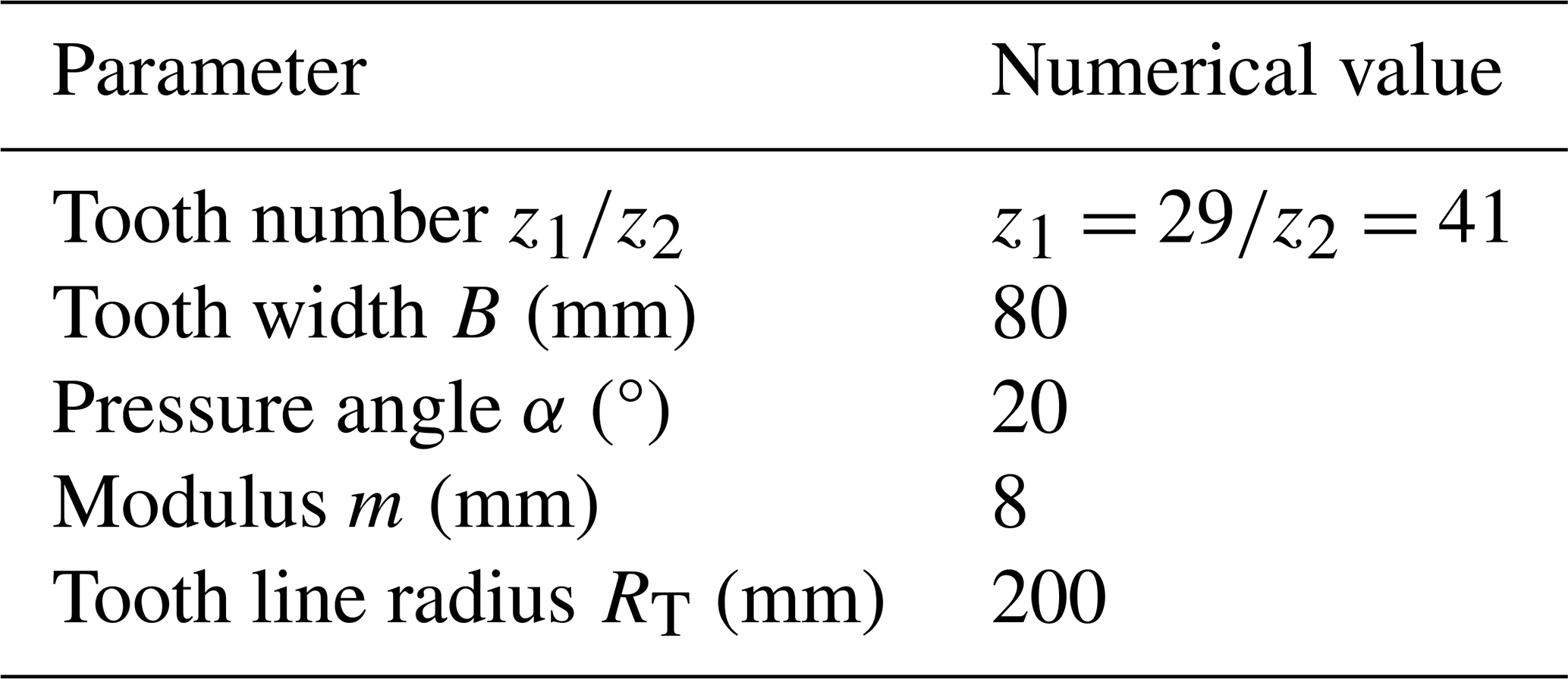
Figure 6 shows the influence of the center distance error on the elliptical contact area. The center distance error ΔE is equal to 1, 2 and 3 mm, respectively. In Fig. 6, it is obvious that the elliptical contact area increases rapidly from zero to a certain value when meshing in and decreases rapidly to zero when meshing out. The reason is that the elliptical contact area of the VH-CATT cylindrical gear is limited between the gear top circle and gear root circle. In addition, the center distance error has no influence on the elliptical contact area in the meshing transmission process, but it has an influence on the rotation angle of the gear pair entering and exiting the meshing. Namely, the center distance error has an influence on the actual meshing line length. The actual meshing line length decreases with an increase in the center distance error.

Figure 7 shows the influence of the axial installation error on the elliptical contact area. The axial installation error ΔA is equal to 0.5, 1, 1.5 and 2 mm, respectively. Figure 8 shows the influence of the driven gear installation rotation error around the x axis on the elliptical contact area. The driven gear installation rotation error around the x axis γx is equal to 0.2, 0.4 and 0.6°, respectively. Figure 9 shows the influence of the driven gear installation rotation error around the y axis on the elliptical contact area. The driven gear installation rotation error around the y axis γy is also equal to 0.2, 0.4 and 0.6°, respectively. According to Figs. 7, 8 and 9, the elliptical contact area also increases or decreases rapidly when meshing in and out. The elliptical contact area increases with an increase in the axial installation error when meshing in. The elliptical contact area decreases with an increase in the axial installation error when meshing out. The actual meshing line length also decreases with an increase in the axial installation error, the installation rotation error around the x axis or the installation rotation error around the y axis. Compared with ΔA, γx and γy, γx has the least influence on the elliptical contact area and the actual meshing line length. The reason is that when there is an installation rotation error around the x axis, the distance between the contact point of the tooth surface and the middle section is the smallest, the curvature change of the contact point is the smallest and the change of the contact area is the smallest.
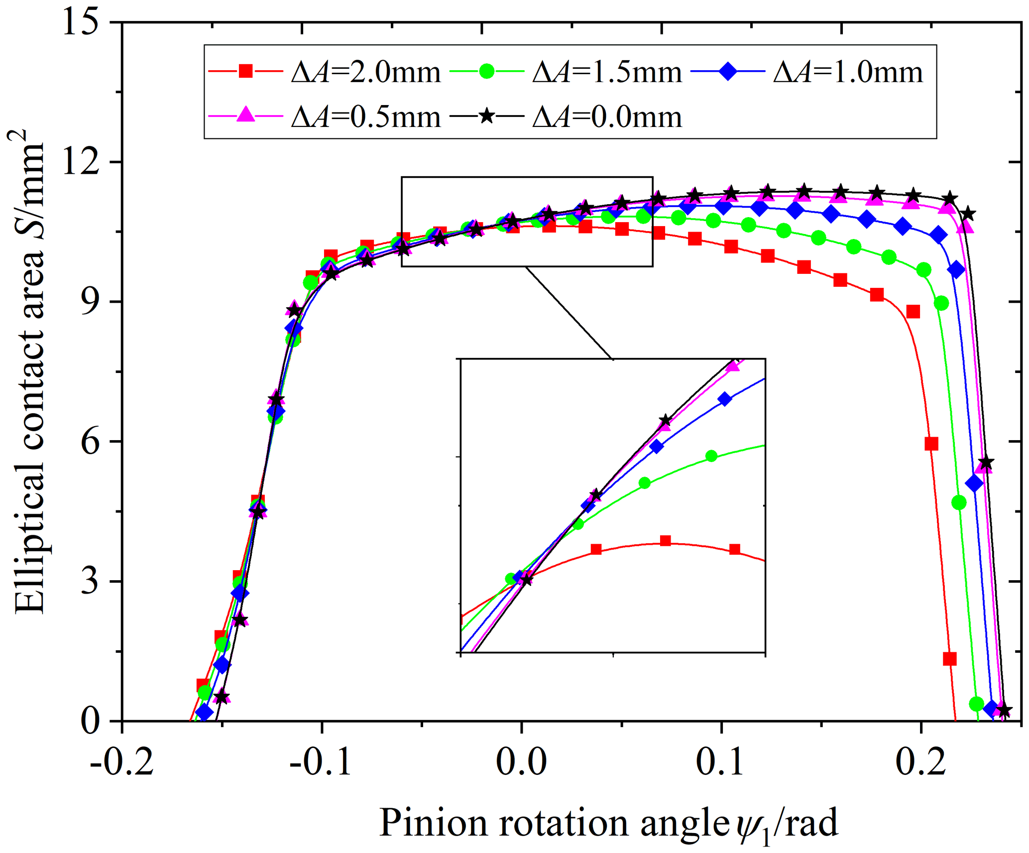
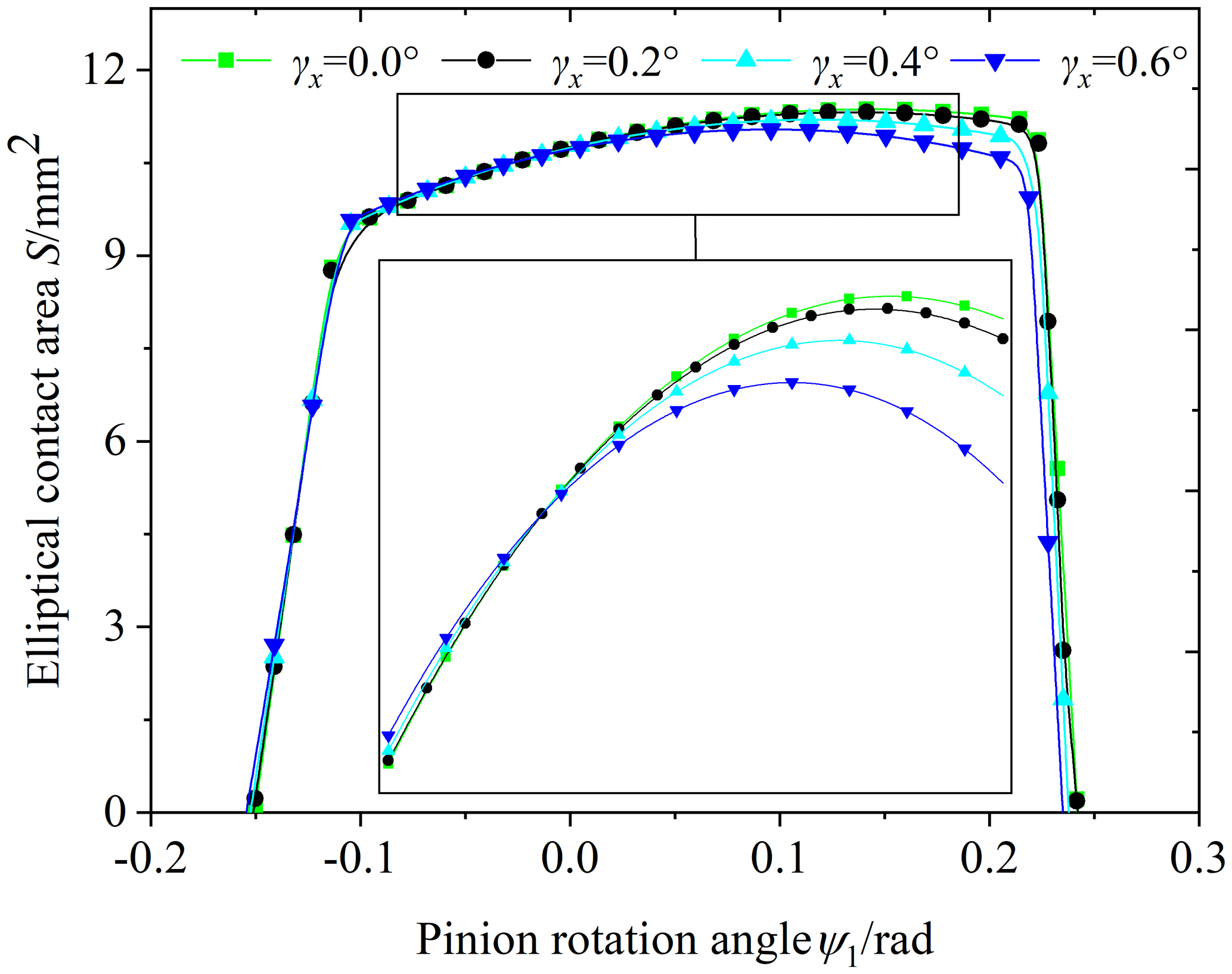
Figure 8Influence of the driven gear installation rotation error around the x axis on the elliptical contact area.

Figure 9Influence of the driven gear installation rotation error around the y axis on the elliptical contact area.
Load tooth contact analysis (called LTCA) is the contact performance analysis of the tooth surface under real load, and LTCA is a bridge between gear geometry design and the dynamic analysis. Therefore, to analyze the influence of installation errors in real contact, a LTCA model was developed and solved by mathematical programming to analyze the influence of installation errors on the load distribution of the tooth surface. The main steps of LTCA are as follows:
- Step 1.
-
Enter basic parameters, generate a point cloud of the tooth surface and develop a 3D model.
- Step 2.
-
Develop a TCA model of the gear pair to calculate tooth surface gap, actual contact points and discrete points on the major axis of the contact ellipse.
- Step 3.
-
Calculate the flexibility matrix of the actual contact points through interpolation.
- Step 4.
-
Develop a LTCA model based on elastic mechanics and calculate the surface load by nonlinear mathematical programming.
5.1 Tooth surface gap of the VH-CATT cylindrical gear
As shown in Fig. 10, in the practical calculation, the paired intersection curves of the gear tooth surfaces are discretized into node pairs to determine the gear surface gap in a plane determined by the long axis vector of the contact ellipse and the normal vector of the meshing point on the tooth surfaces. In Fig. 10, OgXgYgZg is the fixed coordinate system of the driving gear, is the position vector of the tooth contact point, EMGM(ξe) is the vector of the contact ellipse long axis, is the common normal vector of the tooth surface, CMDM is the intersection curves on the tooth surface of the driven gear, AMBM is the intersection curves on the tooth surface of the driving gear, Mj is a discrete point on the long axis of the contact ellipse, Δl is the length of the discrete line, L is a line parallel to and through the Mj point, is the intersection point of L and the tooth surface of the driving gear, is the intersection point of L and the tooth surface of the driven gear and j is the number of the discrete points; all discrete points on the long axis of the contact ellipse are shown in Fig. 10. Based on Fig. 10, the location vector of Mj can be written as
And the expression of the straight-line equation L is
where is the linear equation parameter.

Figure 10Gear surface gap calculation of the VH-CATT cylindrical gear. (a) Teeth surface contact model. (b) All discrete points on the contact ellipse long axis.
It is assumed that the expressions of the intersection points and are as follows: and . The coordinate expressions are the function of the θ1 and φ1 and of the θ2 and φ2, respectively. Since the intersection points are satisfied with the tooth surface and the straight-line equation at the same time, the following geometric conditions are obtained:
The tooth surface gap is mainly composed of two parts, namely the tooth surface normal gap and the tooth surface initial gap. The tooth surface normal gap is the distance from to , and the expression of the tooth surface normal gap can be represented as
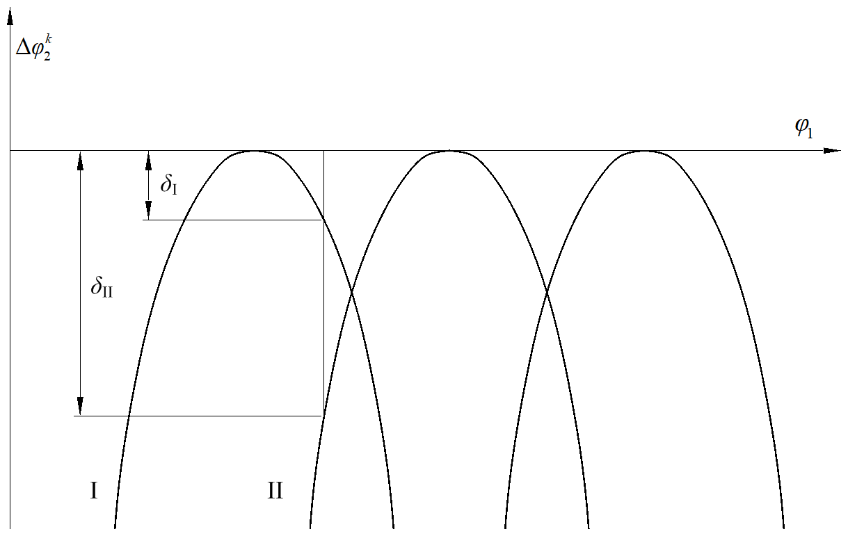
According to Fang (1998), the tooth surface initial gap δ depends on the geometric transmission error. Figure 11 is a schematic diagram of the geometric transmission error. And the tooth surface initial gap is the normal direction displacement of the tooth surface. It is obtained by transforming the geometric transmission error into the normal direction of the tooth surface according to the geometric relationship of the gear pair. Equation (34) is the expression of the geometric transmission error.
where φ10 is the initial angular displacement of the driving gear, φ2(φ10) is the initial angular displacement of the driven gear, φ1 is the angular displacement of the driving gear at a certain time, φ2(φ1) is the angular displacement of the driven gear at a certain time, z1 is the tooth number of the driving gear and z2 is the tooth number of the driven gear.
Therefore, the gear tooth surface gap before deformation is Eq. (35).
5.2 Tooth surface contact point flexibility matrix
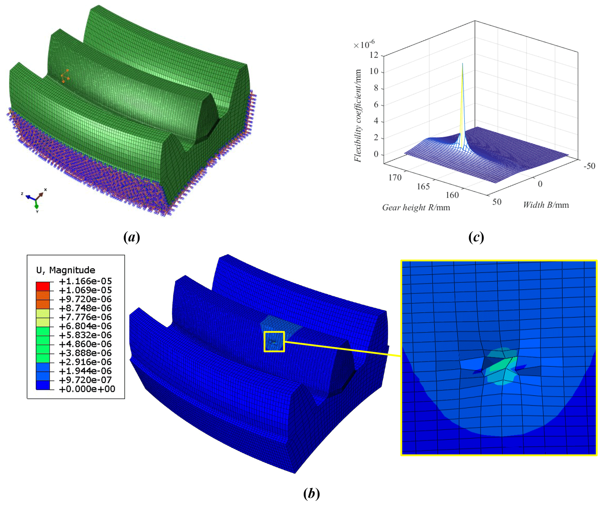
The flexibility matrix is an important parameter in the LTCA model, and it reflects the ability of the tooth surface to resist the deformation of the external load. In the present paper, based on ABAQUS, the finite element model is developed using the Python language, and it was used to calculate the flexibility coefficient of tooth surface under load. Then, the flexibility matrix of the tooth surface nodes is obtained further. Figure 12a is the node load diagram. Figure 12b is the deformation of the tooth surface. Figure 12c is the flexibility coefficient. When the unit normal load is applied to the tooth surface node i ( in turn, and the normal deformation of all nodes on the tooth surface is extracted in turn, then the flexibility matrix of the tooth surface nodes is obtained.
The flexibility matrix of the tooth surface nodes reflects the relationship between the normal load of the nodes on the tooth surface and the normal deformation of the nodes. However, in the analysis of the gear-bearing contact, what is needed is the relationship between the normal load and the normal deformation of the discrete contact points on the long axis direction of the instantaneous contact ellipse, and the flexibility matrix is called the contact point flexibility matrix. However, it is difficult to achieve complete coincidence between the discrete contact points and the tooth surface nodes, so it is necessary to use the existing the flexibility matrix of the tooth surface nodes to obtain the contact point flexibility matrix by the interpolation calculation.
To simplify the interpolation calculation of the flexibility matrix, the tooth surface nodes and contact points are transferred to the cross section of the gear rotating shaft. Namely, x, y, and z coordinates are transformed into r and z coordinates, and . Figure 13 is a schematic diagram of the contact point flexibility matrix calculation principle. In Fig. 13, ∘ is the tooth surface node, ⊚ is the instantaneous contact point, • is the tooth surface node of the interpolation area and the quadrilateral interpolation area is composed of four nodes. The interpolation steps are as follows:
- Step 1.
-
The contact point load is equivalently converted to four nodes in the interpolation area, and the load of the interpolation node Fi is expressed as
where FMc is the contact point load, is the value of the four-node shape function in the interpolation area and .
- Step 2.
-
Firstly, the normal deformation of the whole tooth surface node is calculated by the equivalent load at pi point. And the normal deformation of each contact point is calculated by interpolation. Then, the load calculation and interpolation calculation of four nodes are completed in turn. Finally, the deformation of each discrete contact point is linearly superimposed to obtain the flexibility coefficient of the contact point Mc.

Figure 13Contact point flexibility matrix calculation principle. (a) Tooth surface node. (b) Interpolation calculation.
5.3 Contact mathematical calculation
Figure 14 is the gear-bearing-contact deformation model. ∑1 is the tooth surface of the driving gear, ∑2 is the tooth surface of the driven gear, the solid line is the tooth surface before deformation, the dotted line is the tooth surface after deformation and M is the contact point of the tooth surface. After loading, the contact line is discretized into a series of contact points. j and j′ represent any discrete point on the instantaneous contact line. wj is the tooth surface gap of the j point, and Fj and are the normal load. uj and are the contact deformation under P. Assuming that the driving gear is fixed, sz is the normal displacement of the driven gear under external load. According to Fang (1998), the deformation compatibility equation at discrete point j can be expressed as
where dj is the remaining gap of the tooth surface, if dj=0 and Fj>0 or if dj>0 and Fj=0; fjk and are the flexibility coefficient of the driving gear and driven gear, respectively.

Figure 14Gear-bearing-contact deformation model. (a) Contact deformation of single-tooth pair. (b) Contact deformation of double-tooth pair.
Considering multi-tooth contact and n discrete contact points, the total deformation compatibility equation is written in matrix form:
where [S] is the contact point flexibility matrix, [F] is the contact point load matrix, [w] is the tooth surface gap matrix before deformation, [d] is the remaining gap matrix after deformation, m is the number of contact teeth.
Based on the conditions of deformation coordination, force balance, and non-embedding, the following mathematical model is established to describe the equilibrium state of tooth contact under load:
where P is the tooth surface load, and ; ; I, II represent the first and second pairs of teeth; ; nI and nII are the unit normal vectors of the first and second pairs of teeth; diI and diII are the matrixes composed of the rotation radius of discrete points on the contact line; [e] is the unit diagonal matrix.
In the Eq. (39), S, w, T, and n are the known parameters. P, sz and d are the parameters to be solved.
The load distribution of the tooth surface is an important characteristic which is to reflect the transmission quality of the VH-CATT cylindrical gear. The loaded tooth contact analysis of the VH-CATT cylindrical gear with installation errors plays an important role in the contact performance analysis. According to Sect. 5, the influence of the installation errors on the load distribution was investigated. And the important parameters are shown in Table 1.
Figure 15 shows the load tooth contact analysis of the ideal gear pair. Figure 15a shows the tooth surface gap. In Fig. 15a, the tooth surface gap closed to the middle section of tooth width is zero because the meshing points are located in the middle section of the tooth width. The closer to the tooth width end face, the larger the tooth surface gap is. The tooth surface gap is symmetrical about the middle section of the tooth width. Figure 15b shows the tooth surface load, and Fig. 15c shows the tooth surface maximum load. According to the load distribution, it is obvious that the load of the single tooth is bigger than that of the double tooth, and the load is distributed in the middle section of the tooth width. There is a sudden change in the load in the alternating region of the single-tooth meshing and double-tooth meshing.
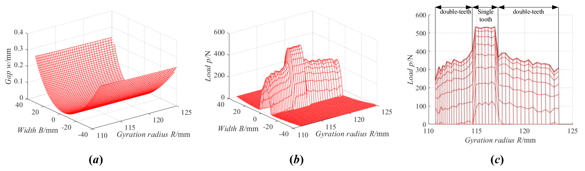
Figure 15Load tooth contact analysis of the ideal gear pair. (a) Tooth surface gap. (b) Tooth surface load. (c) Tooth surface maximum load.
Figure 16 is the load tooth contact analysis of the ideal gear pair with the center distance error, and the center distance error is equal to 2 mm. From Fig. 16, the change law of the tooth surface gap and tooth surface load with the center distance error is the same as that of the ideal gear pair, and the load is still distributed in the middle area of the tooth width. But the actual working area of the tooth surface with the center distance error is obviously smaller than that of the ideal gear pair, and the single-tooth meshing area with the center distance error is obviously greater than the single-tooth meshing area of the ideal gear pair. That is to say, the contact ratio of the VH-CATT cylindrical gear pair with the center distance error decreases, which is consistent with the analysis conclusion in Fig. 6.
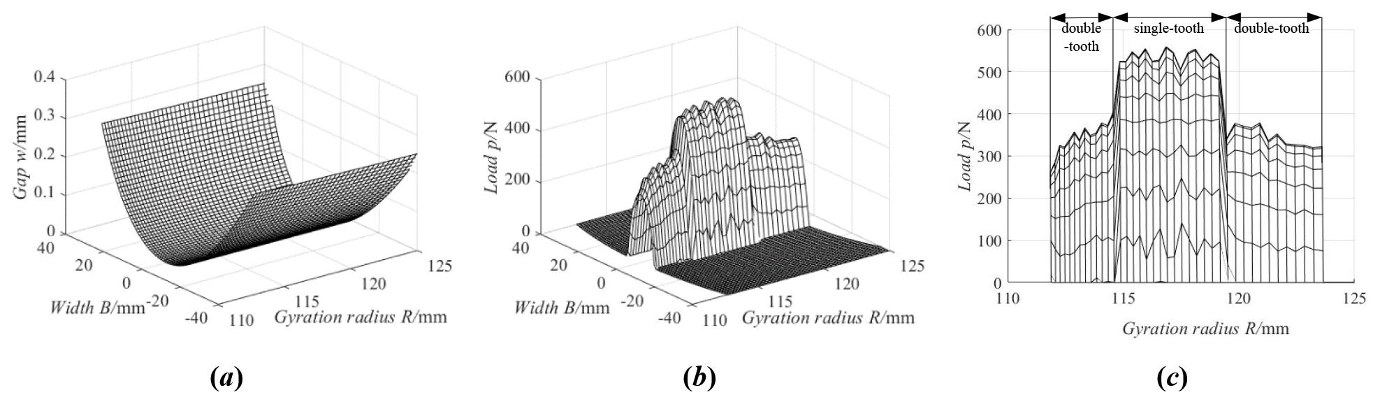
Figure 16Load tooth contact analysis of the ideal gear pair with the center distance error. (a) Tooth surface gap. (b) Tooth surface load. (c) Tooth surface maximum load.
Figure 17 is the load tooth contact analysis of the ideal gear pair with the axial installation error, and the axial installation error is equal to 1 mm. From Fig. 17, the change law of the tooth surface load with the axial installation error is the same as that of the ideal gear pair, but the load distribution area deviates from the middle section of the tooth width. Because the meshing points deviate from the middle section, the position of the tooth surface gap close to zero deviates from the middle section, shown in Fig. 17a. In addition, the single-tooth meshing area with the axial installation error is greater than the single-tooth meshing area of the ideal gear pair.
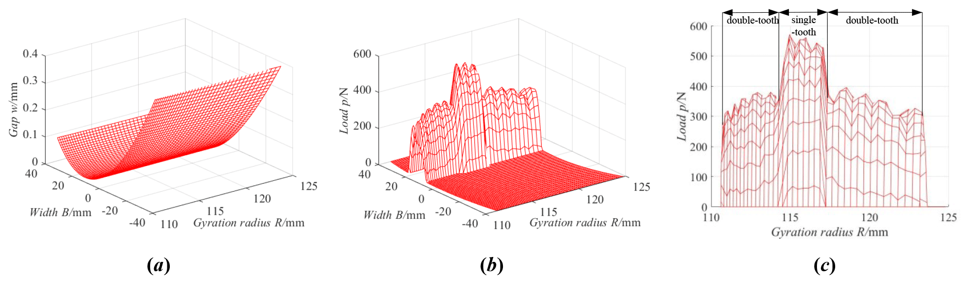
Figure 17Load tooth contact analysis of the ideal gear pair with the axial installation error. (a) Tooth surface gap. (b) Tooth surface load. (c) Tooth surface maximum load.
Figure 18 is the load tooth contact analysis of the ideal gear pair with the installation rotation error around the y axis, and the installation rotation error around the y axis is equal to 0.2°. From Fig. 18, the change law of the tooth surface gap and tooth surface load with the installation rotation error around the y axis is the same as that of the VH-CATT cylindrical gear pair with the axial installation error; the load distribution area also deviates from the middle section. In addition, the single-tooth meshing area with the installation rotation error around the y axis is a little greater than the single-tooth meshing area of the ideal gear pair, the maximum load of the single-tooth meshing zone near the driving gear root increases and the maximum load of the single-tooth meshing zone near the driving gear top decreases.

Figure 18Load tooth contact analysis of the ideal gear pair with the installation rotation error around the y axis. (a) Tooth surface gap. (b) Tooth surface load. (c) Tooth surface maximum load.
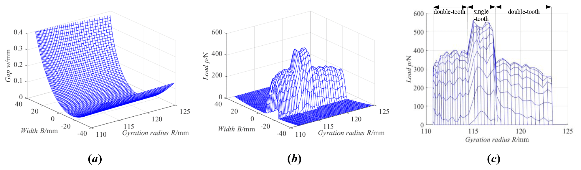
Figure 19Load tooth contact analysis of the ideal gear pair with the installation rotation error around the x axis. (a) Tooth surface gap. (b) Tooth surface load. (c) Tooth surface maximum load.
Figure 19 is the load tooth contact analysis of the ideal gear pair with the installation rotation error around the x axis, and the installation rotation error around the x axis is equal to 0.4°. From Fig. 19 the change law of the tooth surface gap, tooth surface load and tooth surface maximum load with the installation rotation error around the x axis is the same as that of the VH-CATT cylindrical gear pair with the installation rotation error around the y axis, but the load distribution position deviates in the opposite direction.
This paper discusses the contact performance of the variable hyperbolic circular arc tooth trace cylindrical gear considering installation errors. Firstly, the tooth surface equation and the tooth surface contact ellipse of the VH-CATT cylindrical gear were deduced based on the meshing theory, and the tooth surface imprinting experiment was carried out. Next, the tooth contact analysis model of the VH-CATT cylindrical gear was developed, and the influence of the installation error on the elliptical contact area was investigated further. Then, the calculation formulas of the tooth surface gap and contact point flexibility matrix for the VH-CATT cylindrical gear were given. Finally, the load tooth contact analysis mathematical model of the VH-CATT cylindrical gear was developed, and the influence of the installation error on the load distribution was investigated. The main conclusions can be expressed as follows:
- 1.
The contact area of the VH-CATT cylindrical gear will be extended to a line contact within a certain tooth width range, and the gear contact area is in the middle section of the tooth width.
- 2.
The elliptical contact area of the VH-CATT cylindrical gear increases or decreases rapidly when meshing in and out. The center distance error has no influence on the elliptical contact area in the meshing transmission process, but it has an influence on the actual meshing line length. The elliptical contact area closed to the gear top decreases with the increase in the axial installation error, installation rotation error around the x axis and installation rotation error around the y axis. The elliptical contact area closed to the gear root is opposite to that closed to the gear top.
- 3.
The load of the ideal VH-CATT cylindrical gear is distributed in the middle area of the tooth width. The single-tooth meshing area with the installation errors is greater than the single-tooth meshing area of the ideal gear pair. The influence of the center distance error is the most significant. The load distribution area with the axial installation error, installation rotation error around the x axis and installation rotation error around the y axis deviates from the middle section of the tooth width. The maximum load of the single-tooth meshing zone near the driving gear root increases, and the maximum load of the single-tooth meshing zone near the driving gear top decreases, when there are errors γx and γy.
- 4.
In the present paper, the load is only distributed along the long axis of the contact ellipse, and the load distribution along the short axis is ignored; this simplification has a certain influence on the results of load distribution research. At the same time, the influence of installation errors on load transmission error and nonlinear dynamics has not been carried out. Therefore, the main work will focus on the load transmission error, modification design method, vibration and noise reduction of the VH-CATT cylindrical gear in the future.
All the code and data used in this paper can be obtained upon request to the corresponding author (lut_jiang52@163.com).
DM and ZY conceived the presented idea. DM and YL established an overall paper research framework and the model. DM, LB and BJ conducted data calculation for the overall paper. All the authors discussed the results and contributed to the final paper.
The contact author has declared that none of the authors has any competing interests.
Publisher's note: Copernicus Publications remains neutral with regard to jurisdictional claims made in the text, published maps, institutional affiliations, or any other geographical representation in this paper. While Copernicus Publications makes every effort to include appropriate place names, the final responsibility lies with the authors.
The authors would like to thank anonymous reviewers for their valuable comments and suggestions that enabled us to revise the paper.
This work has been supported by the Guizhou Provincial Basic Research Program (Natural Science) (grant no. Qiankehejichu-ZK[2021]yiban273) and the Zunyi Normal University Laboratory Construction and Management Special Project (grant no. Zunshikeshizhuanxiang[2022]1Hao).
This paper was edited by Daniel Condurache and reviewed by four anonymous referees.
Chen, Y.-C. and Lo, C. C.: Contact stress and transmission errors under load of a modified curvilinear gear set based on finite element analysis, P. I. Mech. Eng. C-J. Mec., 229, 191–204, https://doi.org/10.1177/0954406214532907, 2015.
Chen, Z., Hou, L., Duan, Y., Zhao, F., Peng, W., and Luo, L.: Analysis of nonlinear vibration on a cylindrical gear with variational hyperbola and circular-arc-tooth-trace, Adv. Eng. Sci., 49, 209–216, 2017 (in Chinese with English abstract).
Fang, Z.: Model and approach for loaded tooth contact analysis (LTCA) of gear drives, Mechanical Transmission, 2, 2–4, 17, 1998 (in Chinese).
Fuentes, A., Ruiz-Orzaez, R., and Gonzalez-Perez, I.: Computerized design, simulation of meshing, and finite element analysis of two types of geometry of curvilinear cylindrical gears, Comput. Method. Appl. M., 272, 321–339, https://doi.org/10.1016/j.cma.2013.12.017, 2014.
Fuentes-Aznar, A., Ruiz-Orzaez, R., and Gonzalez Perez, I.: Comparison of spur, helical and curvilinear gear drives by means of stress and tooth contact analyses, Meccanica, 52, 1721–1738, https://doi.org/10.1007/s11012-016-0515-y, 2017.
Guo, R., Wei, Y., Liu, Y., Li, D., Yang, D., and Zhao, G.: Analytical solution to contact characteristics for a variable hyperbolic circular-arc-tooth-trace cylindrical gear, Mech. Sci., 12, 923–932, https://doi.org/10.5194/ms-12-923-2021, 2021.
Li, D., Liu, Y., Gong, J., Wei, Y., and Zhao, G.: A novel method for longitudinal modification and tooth contact analysis of non-circular cylindrical gears, J. Mech. Sci. Technol., 36, 6157–6170, https://doi.org/10.1007/S12206-022-1130-6, 2022.
Litvin, F. L.: Gear geometry and applied theory, Shanghai Science and Technology Press, China Shanghai, ISBN: 9787532394203, 2008.
Liu, D., Li, H., Lv, Z., and Cao, Y.: Mutually different tooth surface contact characteristics of a noncircular face gear with intersecting axes, J. Mech. Sci. Technol., 37, 1903–1912, https://doi.org/10.1007/S12206-023-0327-7, 2023.
Liu, Y. and Ma, D.: Surface modification and tooth contact analysis of variable hyperbolic circular-arc-tooth-trace cylindrical gears, Mech. Sci., 13, 909–920, https://doi.org/10.5194/ms-13-909-2022, 2022.
Luo, P., Wu, Y., Liang, S., and Hou, L.: TEHL analysis of VH-CATT cylindrical gear transmission in elliptical contact considering time-varying parameters, Adv. Mech. Eng., 14, 905–919, https://doi.org/10.1177/16878132221081615, 2022.
Ma, D., Wei, Y., and Ye, Z.: Mesh contact impact of circular arc tooth traces cylindrical gears, Journal of Vibration and Shock, 37, 123–131, 2018 (in Chinese with English abstract).
Ma, D., Ye, Z., and Yang, H.: Tooth surface reconstruction and tooth profile geometric analysis of circular arc tooth trace cylindrical gears, T. Famena, 43, 29–44, https://doi.org/10.21278/TOF.43103, 2019.
Ma, D., Liu, Y., and Ye, Z.: Analysis of the tooth surface contact area of a circular arc tooth trace cylindrical gear under load, T. Famena, 45, 79–94, https://doi.org/10.21278/TOF.451018220, 2021a.
Ma, D., Liu, Y., and Ye, Z.: Meshing contact impact properties of circular arc tooth trace cylindrical gear based on rotating knife dish milling process, Math. Probl. Eng., 2021, 8819818, https://doi.org/10.1155/2021/8819818, 2021b.
Ma, D., Liu, Y., and Ye, Z.: Modification design and load tooth contact analysis of a cylindrical gear with variable hyperbolic circular arc tooth trace, Journal of Vibration and Shock, 42, 170–179, 2023 (in Chinese with English abstract).
Wei, Y., Guo, R., and Liu, Y.: Analytical calculation of the tooth surface contact stress of cylindrical gear with variable hyperbolic circular arc tooth trace, Symmetry, 12, 1318, https://doi.org/10.3390/SYM12081318, 2020.
Wei, Y., Li, Z., Liu, Y., Guo, R., Yang, D., Luo, L., and Chen, Z.: Geometric contact characteristics and sensitivity analysis of variable hyperbolic circular-arc-tooth-trace cylindrical gear with error theory considered, Journal of Northwestern Polytechnical University, 40, 679–689, https://doi.org/10.1051/jnwpu/20224030679, 2022a (in Chinese with English abstract).
Wei, Y., Yang, D., Guo, R., Ren, Z., Li, Z., and Luo, L.: Integrated wear prediction model for cylindrical gear with variable hyperbolic circular arc tooth trace under mixed elastohydrodynamic lubrication, J. Mech. Sci. Technol., 36, 4053–4065, https://doi.org/10.1007/s12206-022-0726-1, 2022b.
Wu, J., Wang, L., and Guan, L.: A study on the effect of structure parameters on the dynamic characteristics of a PRRRP parallel manipulator, Nonlinear Dynam., 74, 227–235, https://doi.org/10.1007/s11071-013-0960-2, 2013.
Wu, J., Liu, Z., Yu, G., and Song, Y.: A study on tracking error based on mechatronics model of a 5-DOF hybrid spray-painting robot, J. Mech. Sci. Technol., 36, 4761–4773, https://doi.org/10.1007/s12206-022-0835-x, 2022.
Ye, H., Wu, J., and Huang, T.: Kinematic calibration of over-constrained robot with geometric error and internal deformation, Mech. Mach. Theory, 185, 105345, https://doi.org/10.1016/j.mechmachtheory.2023.105345, 2023.
Zhang, X. and Xie, Y.: Design, meshing characteristics and stress analysis of cylindrical gears with Curvilinear tooth profile, T. Famena, 40, 27–44, 2016.
Zhao, F., Hou, L., Duan, Y., Chen, Z., Chen, Y., and Sun, Z.: Research on the forming theory analysis and digital model of circular arc gear shaped by rotary cutter, Journal of Sichuan University, 48, 119–125, 2016 (in Chinese).
Zhao, F., Hou, L., Chen, Y., and Luo, L.: Mathematical model and generating condition analysis of cylindrical gear with circular-arc-tooth-trace, Journal of Jilin University, 50, 875–885, 2020 (in Chinese).
- Abstract
- Introduction
- Mathematical model of tooth surface and contact ellipse
- Tooth contact analysis model of the VH-CATT cylindrical gear
- Influence of installation errors on the elliptical contact area
- Load tooth contact analysis mathematical model of the VH-CATT cylindrical gear
- Examples of the load tooth contact analysis
- Conclusion
- Code and data availability
- Author contributions
- Competing interests
- Disclaimer
- Acknowledgements
- Financial support
- Review statement
- References