the Creative Commons Attribution 4.0 License.
the Creative Commons Attribution 4.0 License.
 | 23 Apr 2024
Comparison of finite element analysis results with strain gauge measurements of a front axle housing
Gökhan Cen
The strength of the front axle of tractors used on rough terrain is crucial in countries in which agriculture is widespread. Rough agricultural fields, rugged village roads, and ground irregularities cause unexpected reaction forces on the axles. Thus, it is important to analyze the front axle of a tractor with respect to stress, which eventually leads to cracks and premature failure. In this study, ANSYS 13.0 finite element analysis (FEA) software (ANSYS, 2010) was used to predict the strength of a design under loading conditions. ANSYS 13.0 allows products to be tested in a virtual environment and helps to prevent problems that may arise later and accordingly improve them. This study aims to investigate the stresses that occur on the housing of the front axle of a tractor. The reaction forces acting on the front axle housing can cause cracks near the middle of the housing. The study applies a static load of 30 000 N to both hubs at the end of the front axle housing and uses the FEA method to predict and evaluate the maximum stress areas on the housing. Strain gauges are bonded to these locations to measure the real-life stresses on the axle housing in these areas. The results of the FEA and strain gauge measurements were compared, and a correlation was found with 98 % accuracy.
- Article
(10311 KB) - Full-text XML
- BibTeX
- EndNote


Modeling, simulation, and analysis software programs are becoming increasingly reliable with respect to solving complex engineering problems, parallel to developments in the computer hardware world. Products can be designed and analyzed in a virtual environment, and working conditions can be easily and quickly simulated on a computer screen without manufacturing the actual product. Nowadays, it has become very common to model objects in 3-D and analyze them using the finite element analysis (FEA) method in various engineering fields. The engineering analysis programs and methods employed to predict the front axle housing strength involve FEA and empirical testing. ANSYS is a widely used FEA software with capabilities for structural analysis, including static, dynamic, and fatigue analyses. It allows engineers to model and analyze complex structures, such as front axle housings. Advanced FEA software, such as ANSYS, can be used to create detailed 3-D models of the front axle housing and simulate various loading scenarios. The front axle housing geometry is divided into finite elements, and meshing techniques are employed to discretize the structure for numerical analysis. ANSYS provides a range of material models to simulate the behavior of different materials under various loading conditions. Accurate material properties, such as Young's modulus and yield strength, are crucial inputs for FEA simulations. Realistic boundary conditions, including applied loads and constraints, are defined to simulate actual operating conditions. Building physical prototypes of the front axle housing and subjecting them to experimental testing provides real-world data to validate and refine numerical predictions. Strain gages and other sensors are used to measure the deformations, stresses, and loads on the front axle during testing. When using these programs, engineers typically create detailed 3-D models of the front axle housing, define material properties, apply loads and constraints, and then analyze the structure using appropriate numerical methods.
The front and rear axles of tractors are subjected to harsh working conditions; these cause unexpected torsional, bending, and tensile stresses and strains. These eventually lead to deformations, fatigue cracks, and premature failure of the axles. The working conditions of tractors are very difficult, and the safety factors of the components should be higher than those of other vehicles. Tractors face numerous challenges when navigating various terrain, and the importance of the front axles in addressing these challenges is evident. The challenges faced by tractors and the significance of front axles are outlined in the following. Tractors often operate on terrain with uneven surfaces, such as agricultural fields, construction sites, or off-road environments. The front axle plays a crucial role in providing the tractor with stability and balance, helping it navigate uneven terrain smoothly. It ensures that all wheels maintain contact with the ground, thereby enhancing traction and preventing slippage. Tractors frequently carry heavy loads, either in the form of equipment or transported goods. The front axle helps distribute the load evenly between the front and rear wheels, preventing excessive stress on any one axle. Proper weight distribution improves overall stability and prevents overloading, contributing to better performance and longevity. Tractors often need to navigate through tight spaces, make sharp turns, or follow precise paths. The front axle is integral to the steering system, allowing the tractor to maneuver effectively. Front axles with features such as power steering contribute to the ease of operation, reducing driver fatigue and enhancing overall control. Tractors encounter varying soil conditions, ranging from soft mud to hard, compacted earth. The front axle is critical with respect to providing traction and grip. It ensures that the tractor maintains control and forward motion, even in challenging soil conditions. Features such as differential locks on the front axles enhance traction in situations in which one wheel may lose grip. Tractors are often required to use a variety of implements and attachments for different tasks. The front axles need to be adaptable to accommodate different implements. Adjustable front axle widths and configurations contribute to versatility, allowing tractors to efficiently handle various tasks on different terrain. Operating on rough terrain can lead to a bumpy ride for the tractor operator. Front axles equipped with effective suspension systems contribute to shock absorption, providing a smoother and more comfortable ride for the operator. This not only improves comfort but also enhances operator productivity. In summary, the challenges faced by tractors on diverse terrain underscore the crucial role of front axles in ensuring stability, weight distribution, steering control, traction, adaptability, and operator comfort. The design and capabilities of front axles significantly impact the overall performance and efficiency of tractors in various working environments. In contemporary agriculture, tractors play a pivotal role as one of the most essential machines. Their undeniable impact on the agricultural sector is indisputable (Cavallo et al., 2014). Recent years have witnessed rapid technological advancements that have led to the modernization of agriculture. Agricultural machinery and tractors serve as prominent examples of this modernization (Zhang, 2020; Padder, 2021). The quality of mechanical inputs, land utilization, and labor productivity can exhibit significant variation (Lu et al., 2019; Wen et al., 2020). Tractors are multifunctional workhorses that haul loads with attached trailers, performing tasks such as plowing and planting, all while enduring challenging and demanding conditions. These tractors face a multitude of loads, including land operations and the intricate dynamic stresses resulting from the ever-changing terrain that they navigate on farms. The braking and steering systems of tractors closely resemble those found in conventional vehicles. Within a tractor, the front axle shaft plays a pivotal role, facilitating both rotation and bearing the load. Undoubtedly, a tractor's front axle is one of the most critical components, necessitating precise design to ensure that the entire tractor functions optimally, even under the harshest conditions. Axle shafts undergo the strain of axial loads at varying angles contingent upon the specific site conditions. The roughness of the road, influenced by the terrain, exacerbates these challenges and can lead to damage to the axle.
Analysis and prevention of damage are topics of significant importance across various engineering disciplines. Damage analysis, in the realm of engineering, involves a systematic approach aimed at identifying the causes and mechanisms behind the degradation or failure of a component or device. This process seeks to unravel how and why a particular part or device becomes inoperable. While damage analysis, considerations are given to aspects like safety, performance, and economic viability (Hu and Liu, 2011). This comprehensive evaluation is essential not only for preventing future damage but also for gaining a deeper understanding of the system's progression and the quality of the product.
Ultimately, the primary objective is to develop designs and products that adhere to the highest standards and that most effectively meet the expectations of users and consumers. This proactive approach to damage analysis and prevention plays a pivotal role in ensuring the reliability and longevity of engineering solutions. Fracture damage is undoubtedly one of the most undesirable and detrimental forms of damage. As a result, numerous investigations have been carried out on fractured components to conduct a comprehensive damage analysis. In studies related to transmissions, the focus has been on examining axle shafts and joints, revealing instances of damage primarily caused by excessive heat. Several researchers (Yavuz, 2021; Nanaware and Pable, 2003; Hou et al., 2022) have concluded that design flaws within the components were responsible for the damage.
While numerous studies have delved into the analysis of rear axle shafts, it is worth noting that the same level of attention and research has not been dedicated to front axle shafts. Thus, front axle shafts have remained relatively understudied in comparison to their rear counterparts in the existing body of research. The relative lack of attention and research on front axle shafts compared with rear axle shafts may stem from the fact that front axle shafts are often more complex in design, due to the integration of steering components and the need to accommodate turning movements. This complexity may make them more challenging to study and analyze (compared to rear axle shafts). Front axle shafts may also experience lower failure rates or fewer issues compared with rear axle shafts. As a result, researchers and engineers may prioritize studying components that are more prone to failure or issues, leading to a focus on rear axle shafts. Additionally, rear axle shafts are often subjected to more stress and torque, especially in high-performance or heavy-duty vehicles. This higher stress level may lead to more frequent failures and, consequently, more research attention.
It is essential to recognize that the failure or fracture of a front axle shaft can have severe consequences, potentially resulting in fatalities, injuries during transportation, and substantial financial losses. Typically, such failures can be attributed to improper design or other metallurgical factors, which often lead to fractures in rear axle shafts (Hou et al., 2022; Su et al., 2021; Aliakbari et al., 2022; Cheng et al., 2022). Several other researchers have undertaken simulation studies to estimate the extent of damage. Through these simulations, they were able to draw conclusions indicating that areas of damage and high stress levels exhibited remarkable similarity in their findings (Zhao et al., 2021; Hou et al., 2022; Vučetić et al., 2022; Suresh Kumar and Kumaraswamidhas, 2021).
The dynamic stress spectrum records the load history over time, offering insights into the overall structural state of the machine (Shao et al., 2021; Bayrakçeken et al., 2007). Tractors boast braking and steering systems akin to those found in other vehicles. Among the integral components, a tractor's front axle shaft plays a vital role, facilitating rotation and bearing substantial loads. The front axle of the tractor ranks among the most critical components, demanding a flawless design to ensure optimal performance under extreme conditions. Axle shafts must contend with axial loads at varying angles contingent upon the site conditions. The ruggedness of the terrain and road quality further compound these challenges, potentially leading to damage to the axles. The front axle housing is one of the essential parts of the tractor, and it continuously works under difficult conditions and experiences heavy static and dynamic forces (Reimpell et al., 2001). The axle housing is an enclosed structure to protect the shafts, roller bearings, and different driving units from dirty environmental conditions. Tarighi et al. (2011) studied a light agricultural tractor that had increased static load on its front axle housing. Using FEA, they found that the safety factor for the axle was 1.05, and they mentioned that this value is very low for an axle that works under dynamic loading conditions. Oyyaravelu et al. (2012) carried out a FEA for the front axle assembly of a tractor using the ANSYS fatigue design module. They found that the stress levels exceeded safe stress values and that failure was unavoidable. Shao et al. (2011) investigated early fracture of the axle housing on mining trucks by measuring the dynamic strain using strain gauges and then employing FEA. Shamsuddin et al. (2014) studied the stress distribution and premature failure of the axle housing of a heavy vehicle with a high loading capacity using the ANSYS FEA software. Bai et al. (2011) built a model for a light-truck driving axle housing, and they analyzed the model with ANSYS software to establish the maximum equivalent stress and the maximal displacement value of the drive axle housing. They found that the maximum equivalent stress of the drive axle housing under various conditions was less than the allowable stress value. They also showed that the drive axle housing had enough strength and rigidity, meeting the requirement of the structural design.
In this study, the stresses arising under the influence of front axle reaction forces in the front axle housing were calculated using the ANSYS 13.0 finite element software package (ANSYS, 2010). The results obtained from this analysis were then compared with the stress–strain calculations based on the resistance change in the strain gauge in the established test rig setup.
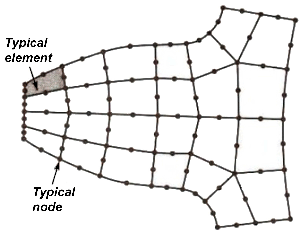
Figure 1A 2-D view of nodes (Cook, 1995).
In the mechanical engineering field, engineers often use various software tools for stress and strain analysis. Some of the most used programs include ANSYS, ABAQUS, COMSOL Multiphysics, SolidWorks, Nastran, and AutoCAD Mechanical. The choice of software largely depends on factors such as the specific requirements of the analysis, the type of structures or systems being studied, and the availability of the software at the research institution.
In this research endeavor, the primary focus is on the resolution of stresses within the front axle housing, precipitated by the impact of reaction forces exerted on the front axle hubs. The analytical approach adopted involves the utilization of the ANSYS 13.0 finite element software package, a sophisticated computational tool employed for structural analysis and simulation. The primary objective is to computationally unravel the intricate stress distribution resulting from the forces. Subsequently, the acquired numerical results were subjected to a meticulous comparative analysis. This involves juxtaposing the computational findings with empirical data obtained through strain gauge measurements in a systematically designed experimental setup. The strain gauge serves as a transducer that facilitates the conversion of mechanical deformation into measurable electrical signals. The ensuing stress–strain calculations, grounded in the strain gauge's resistance variations, establish a meaningful correlation between the computational predictions and real-world experimental observations. This methodology contributes to a comprehensive understanding of the mechanical behavior of the front axle under operational conditions by blending theoretical insights derived from computational simulations with empirical evidence obtained through carefully orchestrated experimental procedures.
FEA of the front axle housing, subjected to a loading of 30 000 N from the front axle hubs, was conducted following the procedure outlined below. Initially, static structural simulation was defined as the type of analysis, and GGG50 gray spheroidal cast iron material was selected from the material library. Subsequently, the geometry of the front axle housing and the connections between components were specified in the ANSYS design modeler section. After geometry creation, meshing was performed using structural 10-node tetrahedral elements. Following the meshing process, the reaction forces, exerted by 30 000 N on the front axle hubs, and the boundary conditions were defined. The maximum principle stress hypothesis was employed as the strength theory because the front axle housing, which is made of spheroidal graphite cast iron, exhibits brittle behavior according to fracture theory. We solved the problem using the Newton–Raphson iteration method, which is a linear solution approach. This method was selected because of its effectiveness in iterative convergence to the solution in the context of specified loading conditions and material properties.
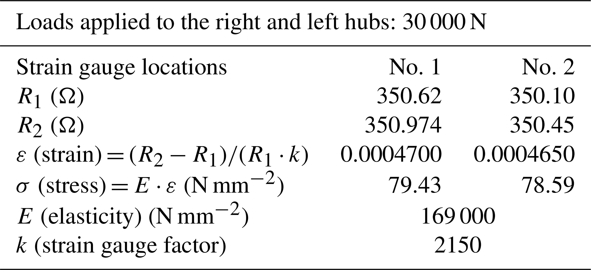
Table 3Resistance, stress, and strain values in strain gauge areas no. 1 and no. 2.
2.1 Computer-aided FEA of the front axle housing
The fundamental approach of the finite element method is to transform any continuous quantity, such as temperature, pressure, stress, or displacement, into a model formed by the assembly of small and continuous elements. In the finite element method, the structure is divided into many elements with predefined behavior. These elements are then reassembled at points called “nodes” to obtain sets of equations. An example of the mesh and nodal points used in the study is given in Fig. 1.
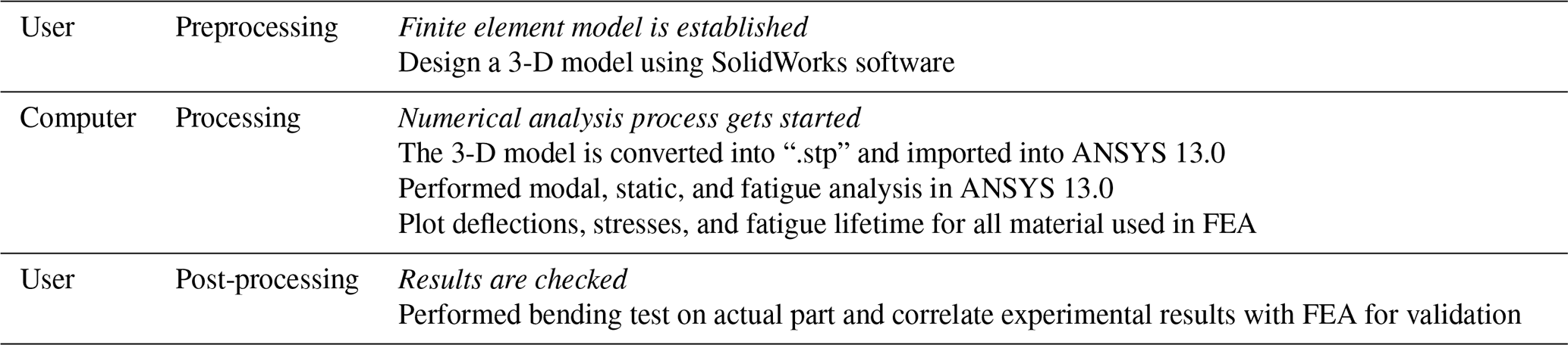
In this study, the FEA was performed using the ANSYS 13.0 software, and computer-aided design (CAD) modeling was carried out with SolidWorks. The methodology used to realize the analysis is given below (see Table 1).
A set of 3-D element equations were established for a solid body by taking an extremely small cubic volume at any point. Each surface of the cube has surface stress, normal stress, and two shear stress components. As the moments created by the forces about the central axis are in equilibrium, they can be written as follows:
Strain is defined as the displacement per unit length and can be obtained by the derivative of the displacements. It is written as follows:
L is the differential operator matrix:
Constitutive equations, also known as Hooke's law, give the relationship between stress and strain in the material properties of a solid body:
Here, c is a matrix of material-property-dependent constants obtained by experimental methods as follows:
There are 21 independent material constants (cij) in anisotropic materials. In isotropic materials, the following matrix is obtained:
Here, E, ν, and G are the elastic modulus, Poisson ratio, and shear modulus of the material, respectively.
On the other hand, based on the local coordinate system defined on an element, the displacement inside the element is estimated by simple polynomial interpolation using the displacements at the element's nodes. In addition to this, if the interpolation equation of the node points and the strain–displacement equation are substituted into the strain energy equation for an element whose shape functions are defined. The stiffness matrix ke is symmetrical. When the vector sum of the total external forces acting on the node points of the element are written using the Lagrange function and Hamilton’s principle, the following equation is obtained:
This shows the finite element equation of an element with stiffness matrix ke, mass matrix me, and the vector sum fe of the total external forces acting on the node points of the element. If the equation is substituted into the global-coordinate-system-based element equation,
and, alternatively,
The results related to these equations are provided in the following sections.
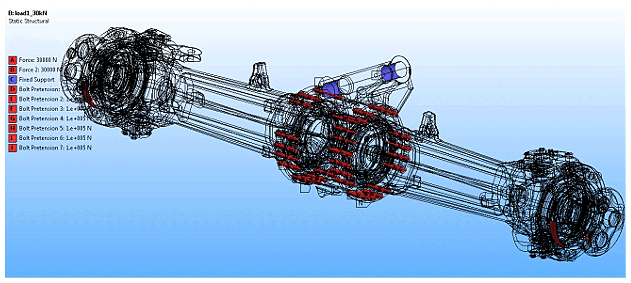
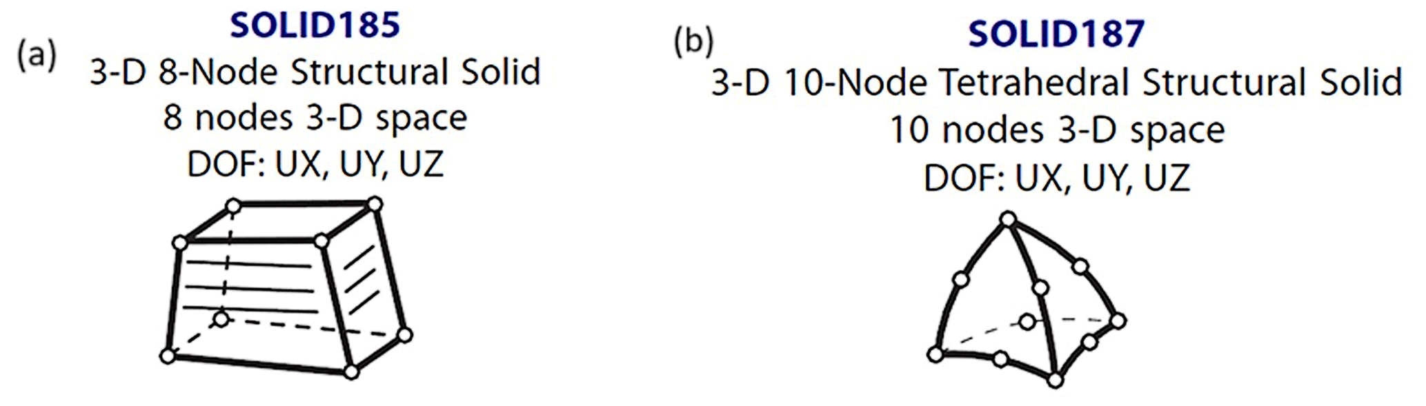
Figure 4(a, b) Finite elements for bolts and kingpins as well as the front axle housing parts (ANSYS, 2010).
2.2 Preprocessing of the CAD model of a HEMA front axle
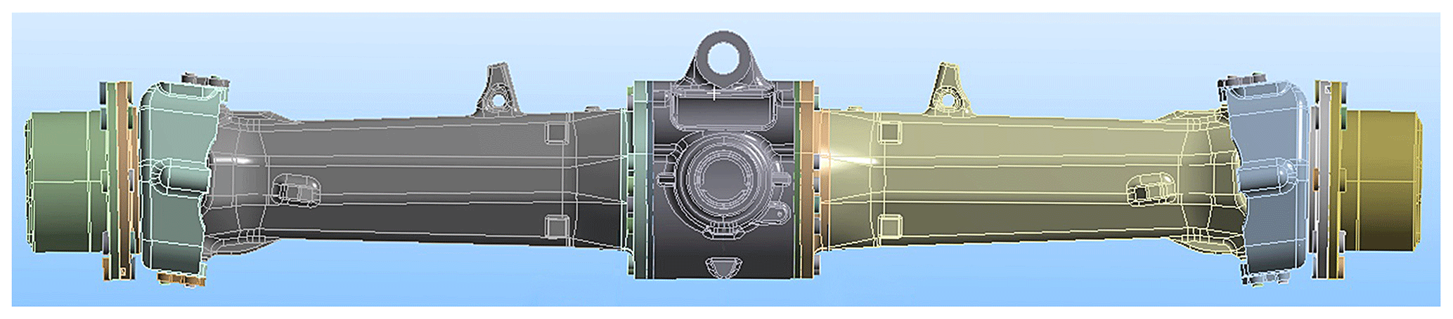
A CAD model of a HEMA backhoe loader front axle is used as the geometrical input for the static FEA. The model is processed with ANSYS 13.0 software. The front axle is modeled in SolidWorks and imported into ANSYS 13.0 (Fig. 2). Figure 2 shows the HEMA front axle CAD model.
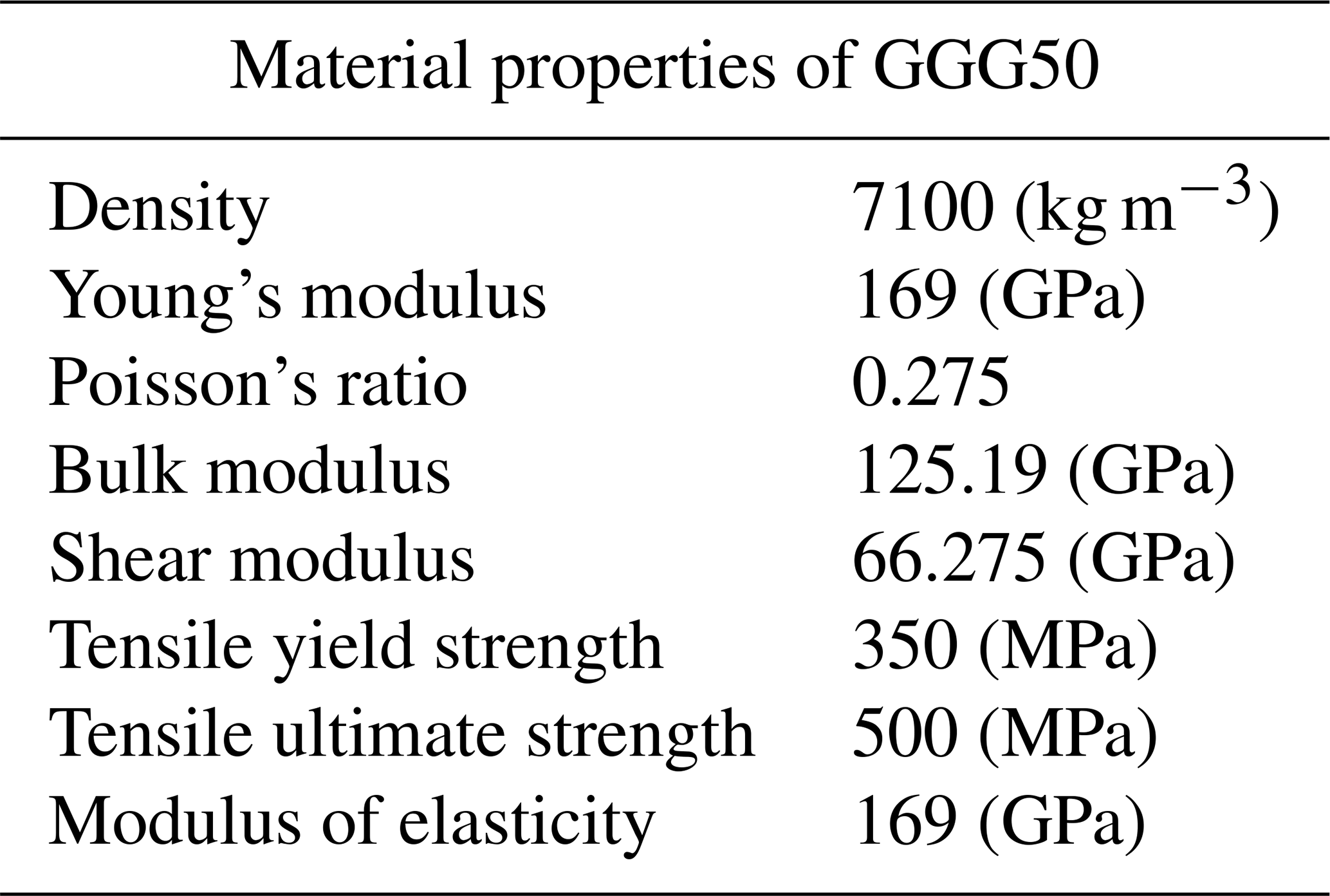
Finite element software can work with shapes created within a CAD model. For the design of the front shaft, CAD modeling was carried out using SolidWorks, and then further modifications were made using ANSYS design modeler software. Before the analysis, a static structural option is selected from the workbench analysis system menu. Because the front axle housing is made of cast iron, GGG50 spheroidal gray cast iron is selected from the material library menu. The material properties of the GGG50 are given in Table 2.
To define the pre-tensions for the bolts on the front axle, first local coordinates are allocated. From the connection menu, contacts between bolts, flanges, bearings, and the front axle housing are defined. Generally, contacts between the touching surfaces are defined as frictionless contacts, bolted areas as bonded contacts, and bearings and their housing as bonded contacts. During the FEA, 100 000 N pre-tension was applied to the M16 bolts connecting the front axle housing to the mid-body section (see Fig. 3).
The process of selecting pre-tension and hub loads in FEA is vital to ensure the accuracy and reliability of the simulation. A pre-tension force of 100 000 N is applied to the M16 bolts based on engineering considerations and design requirements. This force is chosen to ensure that the bolts remain under tension, even under the expected operational loads and conditions. The specific value of 100 000 N is based on anticipated loads, safety margins, and material properties.
Additionally, the hub loads, which are the forces that act on the bearings and their housing, are determined based on the expected loads during operation. These loads include the weight of the vehicle, dynamic loads, and other forces acting on the axle. By applying realistic loads, the FEA can simulate the actual working conditions of the system. It allows for the evaluation of whether the components can withstand these loads without failure and whether any modifications to the design are necessary.
2.3 Finite element mesh structures
To construct the mesh structure in FEA, SOLID185 structural solid hexahedral elements are used for bolts and kingpins (see Fig. 4a), while SOLID187 structural solid tetrahedral elements are used for other parts (see Fig. 4b). Both elements have plasticity, hyper-elasticity, tensile stiffness, creep, high deformation, and a high strain capacity. SOLID185 and SOLID187 are the types of elements used in the modeling of 3-D solid structures. SOLID185 is an 8-node element type with 3 degrees of freedom, whereas SOLID187 is a 10-node element type with 3 degrees of freedom.
The dimensions of the elements in the mesh structure generally vary between 4 and 12 mm. In the finite element model of the front axle housing, there are 792 419 node points and 466 821 elements (see Fig. 5).
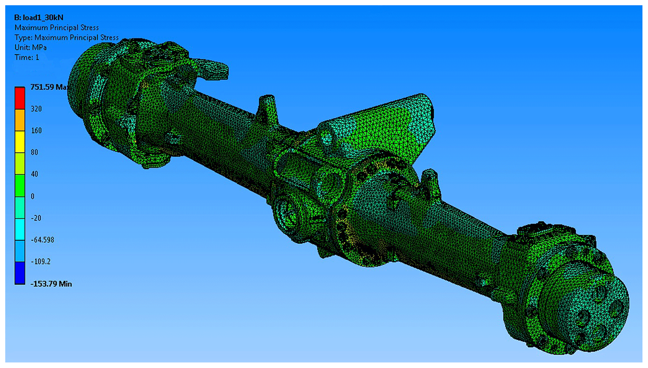
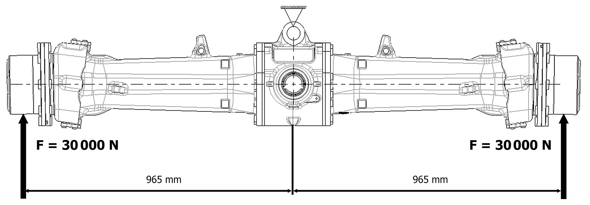
The problem was solved using the Newton-Raphson iteration method, which is the linear solution method. As the material of the front axle housing to be analyzed is spheroidal graphite cast iron (ductile iron) with a brittle behavior, the maximum principal stress hypothesis was used as the strength theory. The front housing is fixed from the mid-axis, and 30 000 N force is applied to both hubs. The distance between the hubs to the mid-axis is 965 mm (see Fig. 6).
The area with the highest stress value obtained from the FEA has been subjected to stress convergence control, where strain gauges will be attached. The convergence change in stress has been found to be 0.67 %, indicating that this value represents convergence.
Firstly, the front axle housing was analyzed using the FEA method, and the areas where high stresses occurred were determined. Then, to ensure parallel results with FEA, general-purpose linear pattern strain gauges, which are sensitive to linear elongation, were bonded to these areas (see Fig. 7).
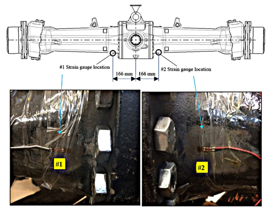
General-purpose linear pattern strain gauges are used to measure stresses on the locations depicted in Fig.7. The properties of the strain gauges are given in Fig. 8 in detail.
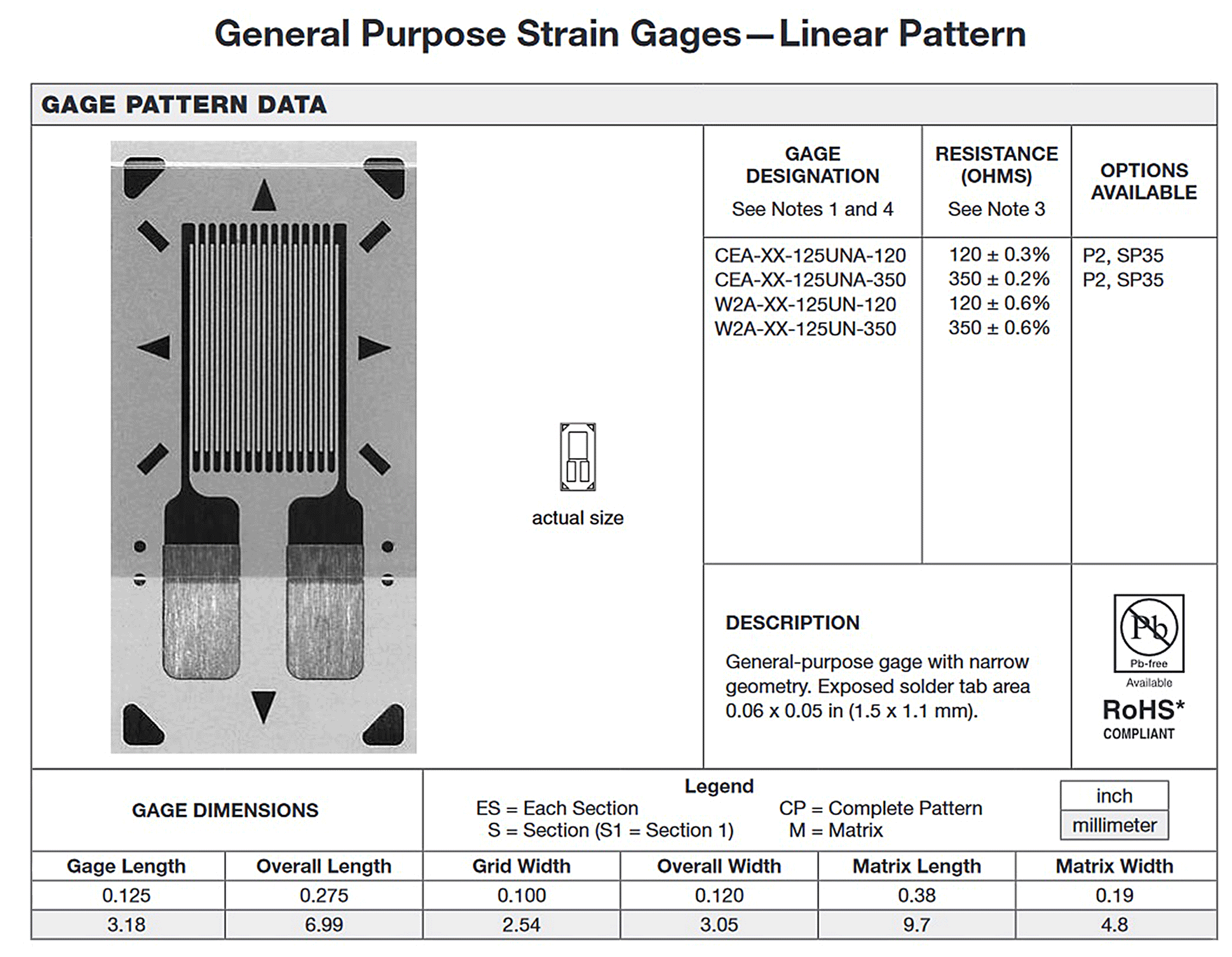
Figure 8Strain gauge properties used in the test (Micro Measurement, 2007).
The surface areas to which strain gauges were to be bonded were first sanded with various graded sandpaper and cleaned with special surface cleaners. Copper wires were welded to the strain gauges using a special welding method, and they were then wrapped up with tape to prevent them from being damaged. A Wheatstone quarter-bridge strain gauge circuit was used to measure the signal values over the strain gauge placed on the front axle housing. Signal values on the strain gauges were measured by a Fluke 179 multimeter.
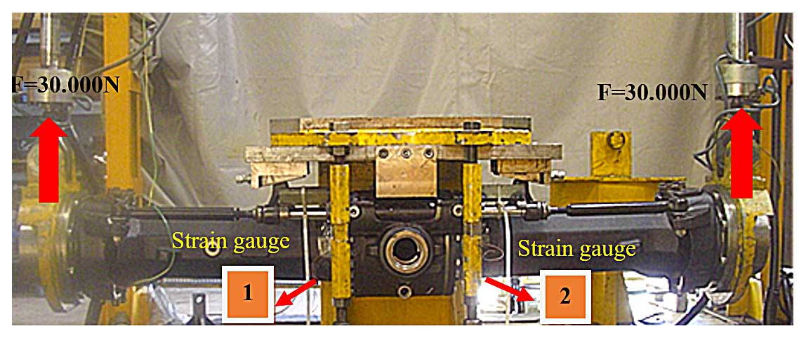
To calculate the stress values where strain gauges were bonded, a special test rig was developed (see Fig. 9). In this test rig, the front axle housing is fixed from the middle, and 30 000 N loads are applied to both hubs by a hydraulic system.
While loads are on, electric current signal values on the strain gauges are recorded in millivolts, and stress values in the strain gauge regions are calculated from these values. After that, these stress values are compared with the FEA results to establish whether they are compatible with each other or not.
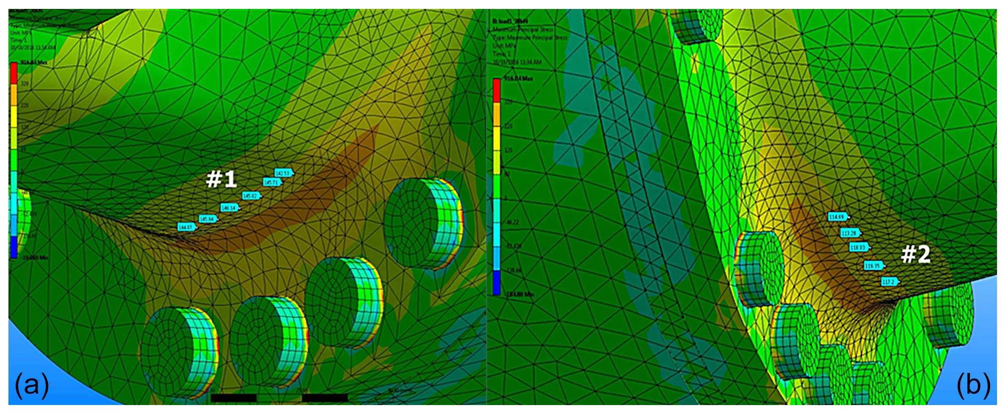
When FEA results under a 30 000 N load were evaluated, it was found that the stress value in the no. 1 strain gauge bond location was 81.05 MPa (see Fig. 10a), while the value in the no. 2 strain gauge bond location was 80.95 MPa (see Fig. 10b).
When a 5 V direct current is applied through the Wheatstone quarter-bridge strain gauge circuit, the resistance values on the circuit are equal to each other in the absence of loading on the system; therefore, V0=0. As the 30 000 N load is applied to the front axle housing, resistive changes occur on the bonded strain gauges and, eventually, the V0 value also changes. If VEX is taken at 5 V while the 30 000 N load is applied to the hubs, the voltage difference on the strain gauge is 0.001249 V. From the Flux 179 multimeter, the R1 and R2 values obtained are 350.62 and 350.974 Ω, respectively (see Table 3).
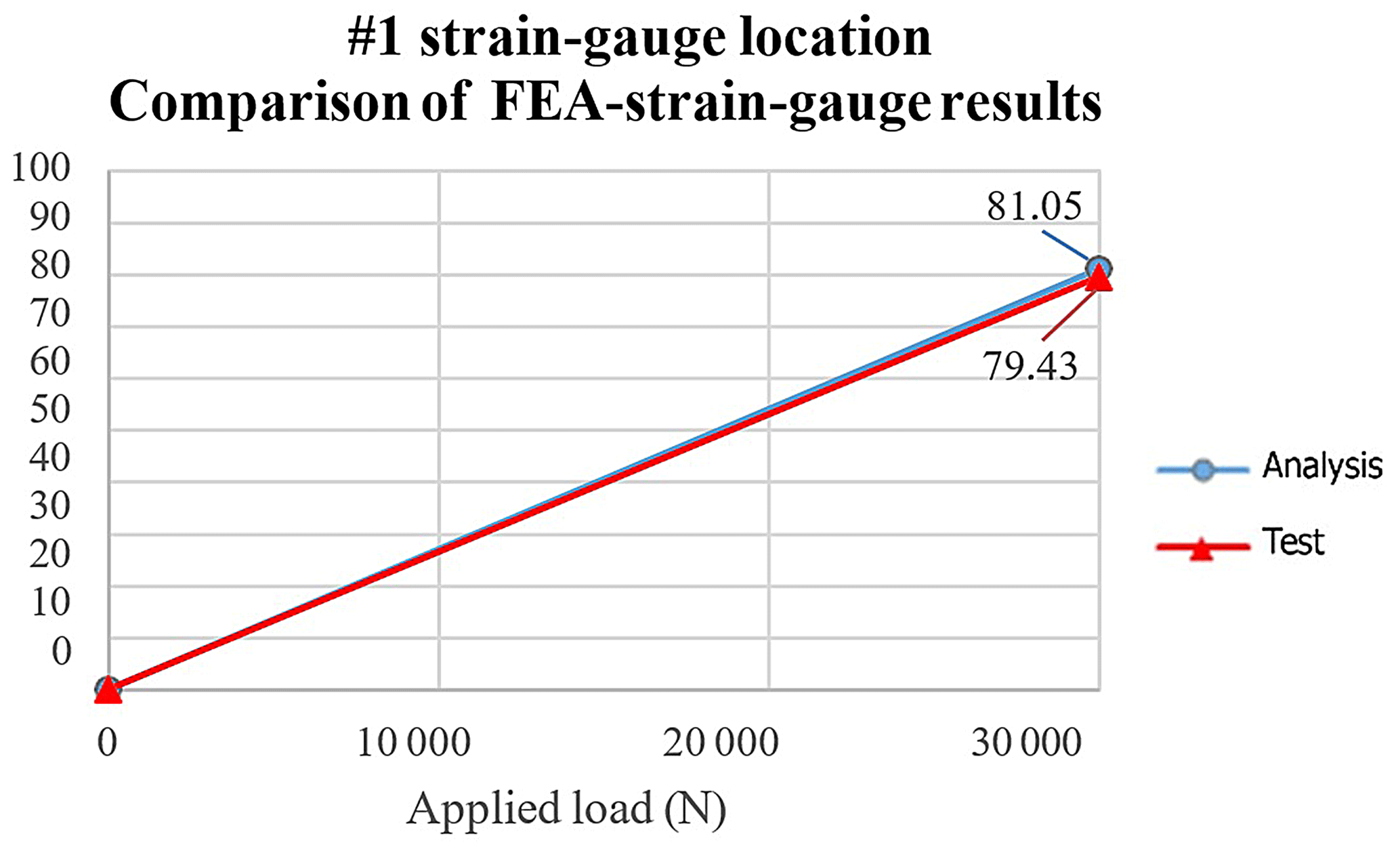
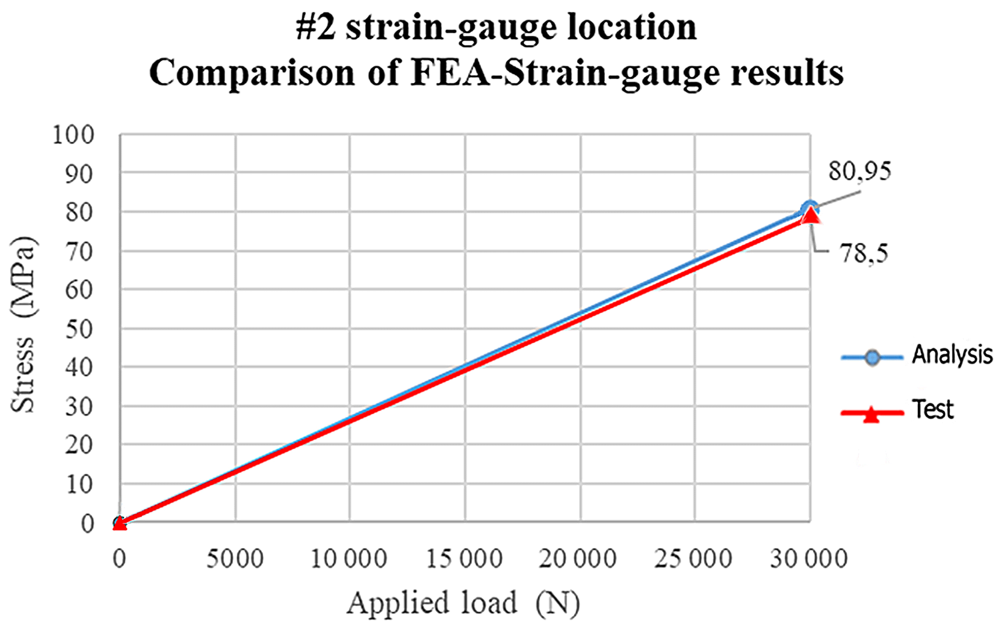
From the measurements made under specified loading conditions in strain gauge regions no. 1 and no. 2 (located at the bottom of the front axle housing), it is seen that the stress values calculated as a result of strain gauge measurements in these regions and the values obtained from the FEA in the same regions are accordance with each other. This consistency can be seen clearly in Figs. 11 and 12.
Although the FEA using the ANSYS FEA software can predict the structural behavior of the machine parts under various loading conditions, the accuracy of the analysis applied with engineering approaches is still being discussed today. Therefore, measurements using strain gauges are extremely important to verify the reliability of the FEA software packages used. In this study, a comparison between FEA and strain gauge measurements shows that a correlation between the engineering analysis and strain gauge measurement values can be established with 98 % accuracy.
Table 4Comparison of stress results with similar publications.
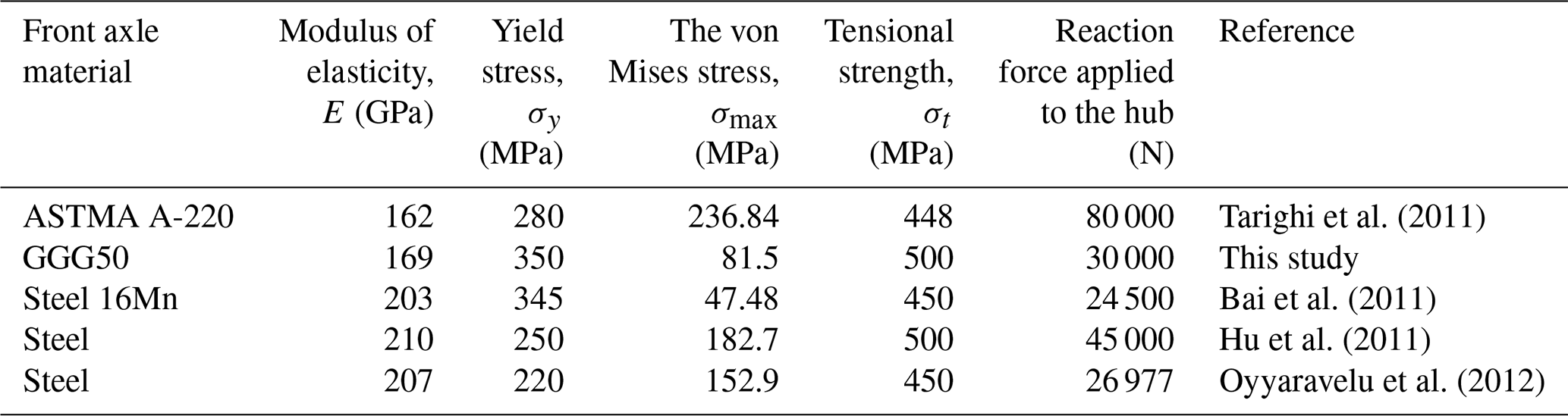
The stress values obtained in this study were compared with those from similar publications in the literature, as shown in Table 4. However, due to the use of different types of materials and the analysis of simplified modeled versions of front axle housing designs, it is quite challenging to directly compare and evaluate the results. When considering the reaction forces applied to the front axle hubs, the stress values obtained in this study are consistent with the literature and, thus, reliable.
In this study, a HEMA backhoe loader front axle housing under 30 000 N static loads, which were applied to the hubs at both ends, was investigated using the FEA method. A finite element model of the front axle housing was developed to predict the location of strain gauges at which the stress values were higher and, thus, areas that were prone to crack and fail.
An excellent correlation between the FEA and strain gauge results was obtained. This shows that the simulated finite element model is well established and that this model can be used for other load cases, such as dynamic loads, torsional forces, and crack initiation and growth under cyclic loading conditions. This finite element model analysis can be extended to evaluate premature fatigue failure of the axle and to find the natural frequency of the front axle housing. The safety factor of the axle housing can be calculated, and its lifespan can be estimated from the FEA stress results.
The key findings of the study are summarized below:
-
The strength behavior of the front axle housing model under various load conditions can be predicted with FEA performed using the ANSYS FEA software.
-
Using strain gauges is crucial to evaluate the consistency of the FEA results with experimental results and prove the reliability of the 3-D model and analysis.
-
In this study, the correlation between FEA and experimental measurements was observed to have an accuracy of up to 98 %.
-
Using the ANSYS FEA software offers a quick solution to design or revise the safety factor to be at least 1.67 as well as for material changes. In this way, the correlation of fatigue tests with a value of 1.67, which is the safety coefficient accepted as the elastic strain limit, can be established more quickly.
-
Based on the point above, the production of more accurate products in a short time and at a low cost can be achieved through analysis–measurement correlation.
-
Cycle life can be calculated using Goodman's dynamic fatigue theory via a static analysis performed in the FEA program.
The data generated during this study are available from Gökhan Cen upon reasonable request.
GC conceived the idea, designed the study, conducted the FEA analysis, and collected the strain gauge measurement data. YG contributed to the data analysis and interpretation and wrote, revised, edited, and proofread the manuscript. YG also supervised the overall study. All authors accepted responsibility for the content of the manuscript and approved its submission.
The contact author has declared that neither of the authors has any competing interests.
Publisher’s note: Copernicus Publications remains neutral with regard to jurisdictional claims made in the text, published maps, institutional affiliations, or any other geographical representation in this paper. While Copernicus Publications makes every effort to include appropriate place names, the final responsibility lies with the authors.
The authors would like to thank the Hema Endustri AR-GE technological development center for providing equipment and support. The authors are also grateful to Aziz Asrak, Selim Güngör, and Raif Karaahmetoğlu for their precious comments, suggestions, and useful help.
This paper was edited by Ali Konuralp and reviewed by two anonymous referees.
Aliakbari, K., Nejad, R. M., Toroq, S. K. P., Macek, W., and Branco, R.: Assessment of unusual failure in crankshaft of heavy-duty truck engine, Eng. Fail. Anal., 134, 106085, https://doi.org/10.1016/j.engfailanal.2022.106085, 2022.
ANSYS: Ansys mechanical nonlinear 13.0, ANSYS [code], https://www.mm.bme.hu/~gyebro/files/vem/ansys_14_element_reference.pdf (last access: 24 February 2024), 2010.
Bai, N. S., Jiao, A. Y., and Liu, S. M.: Finite element analysis of drive axle housing with Ansys workbench, Appl. Mech. Mater., 215–216, 717–720, https://doi.org/10.4028/www.scientific.net/AMM.215-216.717, 2011.
Bayrakçeken, H., Taşgetiren, S., and Yavuz, İ.: Two cases of failure in the power transmission system on vehicles: A universal joint yoke and a drive shaft, Eng. Fail. Anal., 14, 716–724, https://doi.org/10.1016/j.engfailanal.2006.03.003, 2007.
Cavallo, E., Ferrari, E., Bollani, L., and Coccia, M.: Attitudes and behaviour of adopters of technological innovations in agricultural tractors: A case study in Italian agricultural system, Agr. Syst., 130, 44–54, https://doi.org/10.1016/j.agsy.2014.05.012, 2014.
Cheng, G., Guo, F., Zang, X., Zhang, Z., Jia, X., and Yan, X.: Failure analysis and improvement measures of airplane actuator seals, Eng. Fail. Anal., 133, 105949, https://doi.org/10.1016/j.engfailanal.2021.105949, 2022.
Cook, R. D.: Finite element modeling for stress analysis, John Wiley & Sons, ISBN 0-471-10774-3, 1995.
Hou, N., Ding, N., Qu, S., Guo, W., Liu, L., Xu, N., Tian, L., Xu, H., Chen, X., Zairi, F., and Wu, C. M. L.: Failure modes, mechanisms and causes of shafts in mechanical equipment, Eng. Fail. Anal., 136, 106216, https://doi.org/10.1016/j.engfailanal.2022.106216, 2022.
Hu, D. F. and Liu, W. H.: Finite element analysis of the tractor front axle housing based on Ansys, Appl. Mech. Mater., 105–107, 168–171, https://doi.org/10.4028/www.scientific.net/AMM.105-107.168, 2011.
Lu, H., Xie, H., and Yao, G.: Impact of land fragmentation on marginal productivity of agricultural labor and non-agricultural labor supply: A case study of Jiangsu, China, Habitat Int., 83, 65–72, https://doi.org/10.1016/j.habitatint.2018.11.004, 2019.
Micro measurement: General purpose strain gages – Linear pattern, https://docs.micro-measurements.com/?id=2541 (last access: 24 February 2024), 2007.
Nanaware, G. K. and Pable, M. J.: Failures of rear axle shafts of 575, DI tractors, Eng. Fail. Anal., 10, 719–724 https://doi.org/10.1016/S1350-6307(03)00057-8, 2003.
Oyyaravelu, R., Annamalai, K., Kumar, M. S., Naiju, C. D., and Michael, J.: Design and analysis of front axle for two wheel drive tractor, Adv. Mat. Res., 488–489, 1808–1812, https://doi.org/10.4028/www.scientific.net/amr.488-489.1808, 2012.
Padder, A. H.: An analysis of dissemination of technology and growth in agriculture of Jammu & Kashmir, International Journal of Research and Analytical Reviews, 8, 827–837, https://www.ijrar.org/papers/IJRAR21D1592.pdf (last access: 20 April 2024), 2021.
Reimpell, J., Stoll, H., and Betzler, J. W.: The automotive chassis: Engineering principles, 2nd Edn., Butterworth Heinemann, Oxford, p. 39, ISBN 0 7680 06570, 2001.
Shamsuddin, K. A., Tajuddin, M. S., Amzari, M. M., Aris, M. M., and Zahelem, M. N.: Stress distribution analysis of rear axle housing by using finite elements analysis, Int. J. Eng. Sci., 3, 53–61, 2014.
Shao, X., Song, Z., Yin, Y., Xie, B., and Liao, P.: Statistical distribution modelling and parameter identification of the dynamic stress spectrum of a tractor front driven axle, Biosyst. Eng., 205, 152–163, https://doi.org/10.1016/j.biosystemseng.2021.03.003, 2021.
Shao, Y., Liu, J., and Mechefske, C.: Drive axle housing failure analysis of a mining dump truck based on the load spectrum, Eng. Fail. Anal., 18, 1049–1057, https://doi.org/10.1016/j.engfailanal.2010.12.023, 2011.
Su, C., Pan, A. X., Gong, Y., and Yang, Z. G.: Failure analysis on rubber universal spherical joints for rail vehicles, Eng. Fail. Anal., 126, 105453, https://doi.org/10.1016/j.engfailanal.2021.105453, 2021.
Suresh Kumar, G. and Kumaraswamidhas, L. A.: Design optimization focused on failures during developmental testing of the fabricated rear-axle housing, Eng. Fail. Anal., 120, 104999, https://doi.org/10.1016/j.engfailanal.2020.104999, 2021.
Tarighi, J., Mohtasebi, S. S., and Alimardani, R.: Static and dynamic analysis of front axle housing of tractor using finite element method, Aust. J. Agr. Eng., 2, 45–49, 2011.
Vučetić, N., Jovičić, G., Antunović, R., Sovilj-Nikić, S., Košarac, A., and Jeremić, D.: Integrity assessment of an aircraft cylinder assembly with a crack, Mater. Technol., 56, 389–396, https://doi.org/10.17222/mit.2022.430, 2022.
Wen, C., Xie, B., Li, Z., Yin, Y., Zhao, X., and Song, Z.: Power density based fatigue load spectrum editing for accelerated durability testing for tractor front axles, Biosyst. Eng., 200, 73–88, https://doi.org/10.1016/j.biosystemseng.2020.09.008, 2020.
Yavuz, İ.: Failure analysis of distributor gear, Int. J. Auto. Sci. Tech., 5, 63–66, https://doi.org/10.30939/ijastech..823415, 2021.
Zhang, H.: Research on the application of agricultural engineering technology in agricultural modernization, J. Phys. Conf. Ser., 1699, 12008, https://doi.org/10.1088/1742-6596/1699/1/012008, 2020.
Zhao, X., Wu, S., Bao, J., Ao, N., Peng, W., and Sun, W.: Experimental characterization and numerical modelling on the external impacting of high-speed railway axle EA4T steel, Eng. Fail. Anal., 125, 105449, https://doi.org/10.1016/j.engfailanal.2021.105449, 2021.
- Abstract
- Introduction
- Methodology
- Testing: installation of the strain gauges on the front axle housing
- Experimental part: front axle housing test rig
- Results and discussion
- Conclusions
- Code and data availability
- Author contributions
- Competing interests
- Disclaimer
- Acknowledgements
- Review statement
- References