the Creative Commons Attribution 4.0 License.
the Creative Commons Attribution 4.0 License.
 | 02 Mar 2023
Design and kinematics of a lightweight cruciform continuum robot
Pan Zhou
Jiantao Yao
Hongyu Zhang
Xuanhao Zhang
Shuaiqi kong
Kunming Zhu
The design of new lightweight and dexterous configurations is a major research focus for continuum robotics. This work proposes a cruciform continuum robot. Its unique feature is that it is formed by multiple cruciform-arranged elastic sheets with a single dimension of motion connected in series, and thus it has low-coupling motion characteristics. In addition, the cruciform continuum robot has the advantages of lighter weight (65 g), better dexterity, and higher motion accuracy. In this paper, the forward and inverse kinematics models of the cruciform continuum robot are established by geometric methods based on the assumption of constant curvature, and its workspace is analysed. It is experimentally verified that the tip position errors are less than 1 mm, and the cable length errors are less than 0.4 mm. Further, the cruciform continuum robot is successfully used for the nucleic acid detection simulation experiment, which confirms its good dexterity and man–machine safety. The main contribution of this paper is to provide a new configuration for the lightweight and dexterous continuum robots, and to further provide a reference method for improving their modelling accuracy from the perspective of structure.
- Article
(7385 KB) - Full-text XML
- BibTeX
- EndNote


Different sorts of soft manipulators have been developed to deal with diverse operational tasks and work environments (Rus and Tolley, 2015; Krovi and Nie, 2008; Zhao et al., 2020; Dong et al., 2016; Yarbasi and Samur, 2018; Yu et al., 2018). Continuum robots are known for their flexibility and dexterity, which have significant performance advantages in dealing with unstructured environments and non-cooperative target operations, making them always active at the forefront of robotics research. They can be applied in various fields such as disaster relief (Tsukagoshi et al., 2001; Polygerinos et al., 2017), minimally invasive surgery (Kato et al., 2015; Burgner-Kahrs et al., 2015; Zhu et al., 2021; Wang et al., 2019; Yuan et al., 2017; Bajo and Simaan, 2016), space inspection (Tonapi et al., 2014; Guo et al., 2022), nuclear fusion vessel maintenance (Buckingham and Graham, 2012), and manipulation (Yang et al., 2018; Laschi et al., 2016; Godage et al., 2019; McMahan et al., 2005). The existing continuum robots have two classic structure forms, which are the single-backbone configuration (Kato et al., 2015; Burgner-Kahrs et al., 2015; Yuan et al., 2017; McMahan et al., 2005; Roesthuis and Misra, 2016) and the multi-backbone configuration (Wang et al., 2019; Bajo and Simaan, 2016; Godage et al., 2019). The former is usually driven by cables and the latter often uses rods and variable-length soft actuators as both the backbone and actuation of continuum robots. Among them, the cable-driven single-backbone continuum robots are very popular in medical examinations and minimally invasive surgery due to their compact structure, high motion and positioning accuracy, and relatively large load capacity (Kato et al., 2015; Burgner-Kahrs et al., 2015).
Continuum robots can be regarded as long cantilever beam structures. Thus, their deformation shape is easily affected by their gravity and the load on their tip. This phenomenon becomes more and more significant as length and load increases, which greatly reduces their motion accuracy. One way to tackle this negative deformation is to incorporate variable stiffness techniques into the development of continuum robots, such as the jamming method (Jiang et al., 2014; Bamotra et al., 2019; Miller-Jackson et al., 2019), actuation coupling (Al-Fahaam et al., 2018), solid–liquid conversion (Yoshida et al., 2018), and variable stiffness material (Zhang et al., 2019). However, variable stiffness structures have difficulty quickly responding to the motion of continuum robots and will increase their weight, size, and complexity of control. The lightweight and stable design of continuum structures can effectively alleviate this negative deformation from the root, which has always been the focus of research in the field of robotics.
In order to develop ultra-lightweight continuum robots, researchers have tried to fabricate continuum structures through origami technology (Childs and Rucker, 2021; Santoso and Onal, 2021) and airtight films (Hofer et al., 2021; Hawkes et al., 2017), prominent among which is an ultra-long growth robot based on an airtight film structure (Hawkes et al., 2017). However, the origami continuum structures are generally slightly insufficient in terms of compactness, and the thin film continuum structures are usually not easy to be accurately driven. The development of continuum robots adopting non-contact actuation (such as magnetic – Boyvat et al., 2017; Kim et al., 2019; and light responsive actuation – Qian et al., 2018) is another potential approach to lightweight design because they no longer require actuating components. For example, a long thin continuum robot based on magnetic actuation can move in human organs (Kim et al., 2019), and the hybrid drive of magnetic fields and tendons enables the development of a millimetre-scale soft continuum robot capable of high-precision manipulation (Zhang et al., 2021). However, the workspace of such continuum robots is strictly limited by the medium fields (such as magnetic and light fields), which makes it difficult to develop a robot system that has a large-scale operation range. Tendon-driven continuum robots can have a larger workspace and a lightweight and compact robotic arm. The classic single-backbone continuum robots driven by tendons usually take a flexible member with a circular section as the bending section (Kato et al., 2015; Burgner-Kahrs et al., 2015). Unlike these designs, this paper proposes a novel lightweight continuum robot (named the cruciform continuum robot) using a flexible member with a rectangular section as the bending section. Multiple flexible members are combined to make the cruciform arrangement, which enables the multi-degree-of-freedom motion and the bending coupling reduction in different directions of the continuum robot. These design features give the continuum robot the basic characteristics of large load-bearing beams in the direction without deformation and better bending characteristics in the deformation direction.
Compared with traditional rigid robots, the modelling of continuum robots is relatively complex and difficult, and there is no mature theoretical system yet. Although scholars have put forward the constant curvature hypothesis (Webster and Jones, 2010), Cosserat rod theory (Till and Rucker, 2017; Alqumsan et al., 2019), finite element (Bieze et al., 2018), intelligent algorithm (Braganza et al., 2007), and other methods to build the theoretical model of continuum robots, their high-precision modelling remains a difficulty, which is closely related to their structural configuration. Most existing multi-backbone continuum robots are composed of multiple flexible parallel mechanisms in series, which can be referred to as series-parallel mechanisms (Wang et al., 2019; Bajo and Simaan, 2016; Godage et al., 2019), and existing single-backbone continuum robots are mostly pure-series mechanisms (Kato et al., 2015; Burgner-Kahrs et al., 2015; Yuan et al., 2017; McMahan et al., 2005; Roesthuis et al., 2016). Compared with series-parallel mechanisms, pure-series mechanisms are simpler to model in terms of kinematics and mechanics. The cruciform continuum robot adopts a pure-series cruciform configuration. This configuration can greatly reduce the motion coupling between different bending sections connected in series, and it enables the continuum robot to establish a simpler and more accurate theoretical model. Therefore, the cruciform continuum robot provides a solution to improve the modelling accuracy of continuum robots from the perspective of structure and further lays a foundation for their precise control.
First, the lightweight cruciform continuum robot is discussed, and its special structural advantages are analysed. Then, the kinematic model is derived using geometric methods, and its accuracy is verified experimentally. Finally, the nucleic acid detection experiment fully demonstrates the dexterity, compliance, and good adaptability of the robot.
As shown in Fig. 1, the manipulating system of the continuum robot is mainly composed of two series units in a cruciform arrangement, and each series unit consists of two bending sections in a cruciform arrangement. The bending section is composed of an elastic piece connected with two connectors through an interference fit. The elastic piece as the middle backbone is made of 65 MN spring steel which has good bending properties, and its bending is more regular and controllable. The connector was fabricated by 3D printing technology to reduce the weight of the continuum robot. Each bending section has 1 degree of freedom, which is driven by two evenly distributed cables. As shown in Fig. 1a, the driving cables of the tip bending section thread through the holes in the lowermost disc, each connector in the middle, and its upper disc in turn, with the cables being tied at the upper disc. We route the driving cables of the other bending sections in the same way, with each cable being driven independently by a stepper motor. The robot can perform dexterous manipulation when cables are driven by motors, as shown in Fig. 1b.
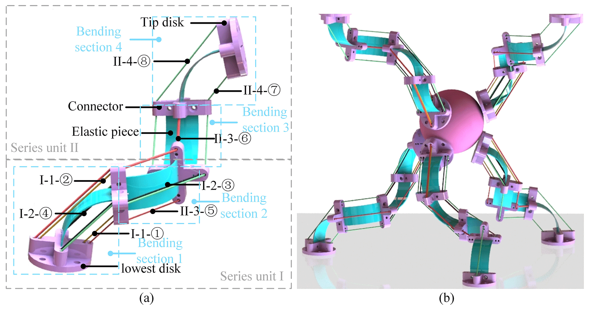
Figure 1(a) Three-dimensional model of the continuum robot and its driving cable layout (I and II are the labels of each series unit; 1, 2, 3, and 4 are the labels of each bending section; and ① to ⑧ are the labels of each cable). (b) The dexterous manipulation of the continuum robot.
Unlike most existing single-backbone continuum robots that use rod-like structures as the backbone, the cruciform continuum robot uses sheet-like structures in a cruciform arrangement as the backbone for the following reasons. The cruciform arrangement of the sheet-like structures enables each bending section to have a larger bearing capacity in the non-deformation direction and better bending characteristics in the deformation direction. In addition, the width direction of the first elastic piece is arranged to be consistent with its gravity direction. Due to the much larger moment of inertia along the axis perpendicular to the sheet, this arrangement can reduce the initial deformation caused by its gravity and external load. Thirdly, the pure-series connection and cruciform arrangement of the continuum robot can greatly reduce the coupling between bending motions in different directions. For example, the series unit can bend up and down or left and right independently, which avoids the movement coupling of two bending directions.
As shown in Fig. 2, we chose a thickness of 0.2 mm for the tip elastic piece and a thickness of 0.3 mm for the other three elastic pieces in the prototype. The thickness of the tip elastic piece is slightly smaller than that of the other three elastic pieces, to reduce the influence of its driving cables on the other elastic pieces when bending the tip elastic piece. The robot is 255 mm long and has a radius of 21 mm. In terms of length, its average mass per millimetre is 0.255 g, and from its cylindrical envelope volume, its average mass per cubic millimetre is 0.0002 g. Its weight is light, which is 65 g. The continuum robot can move automatically or by manual remote control. The working range and motion capability of the continuum robot are effectively improved when it is installed on an omnidirectional mobile platform. The proposed continuum robot has 4 degrees of freedom, but by adding the series units, it can get longer and have more degrees of freedom, enabling it to complete more complex operations.

3.1 Forward kinematics
In order to obtain the forward kinematics solution of the series unit, we first have to get the forward kinematics solution of the bending section. Due to the good bending properties of the elastic piece, its forward kinematics solution can be found using geometric methods based on the assumption of constant curvature. As shown in Fig. 3, the tip coordinate of the first bending section in the task space can be expressed by the lengths of its driving cables. Since the arc length S of the bending curve of the bending section is constant, the position of the bending section can be expressed by the curvature k1 of the bending curve. The bending direction of the first bending section about the y0 axis shown in Fig. 3 is defined as a positive bending direction. The maximum bending angle α of the elastic piece is limited to less than 85∘, and it can exhibit good bending characteristics.
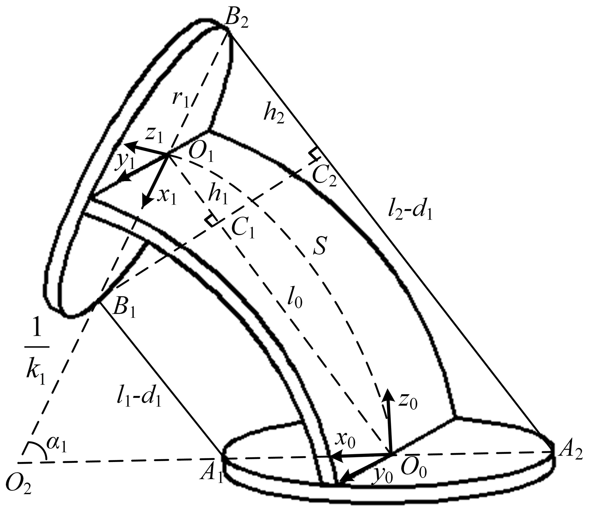
We first can obtain
where l0 is the chord length of the bending curve of the first bending section, l1 and l2 are the driving cable lengths of the first bending section, and d1 is the thickness of the tip connector of the first bending section.
As shown in Fig. 4, we get
where r1 is the radius of the tip connector of the first bending section, and R1 is the radius of the first bending section.
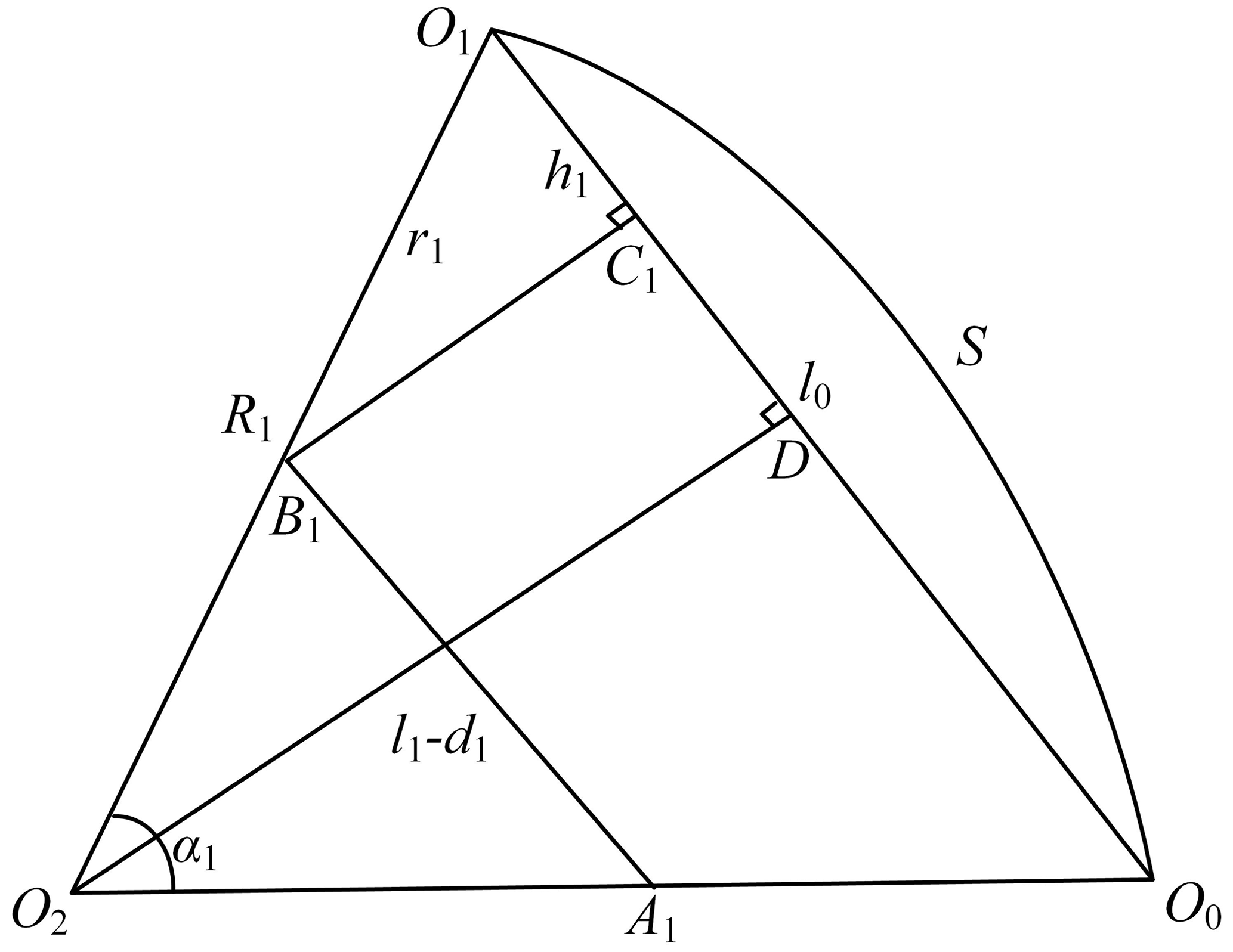
Substituting Eqs. (1) and (2) into Eq. (4) yields R1 in terms of cable lengths as
As shown in Fig. 5, using the same method, we obtain
where R2 is the radius of the second bending section, l32 and l42 are a section of the driving cables of the second bending section which is between the top plane of the lower connector and the top plane of the upper connector of the second bending section, and d2 and r2 are the thickness and radius of the tip connector of the second bending section, respectively.
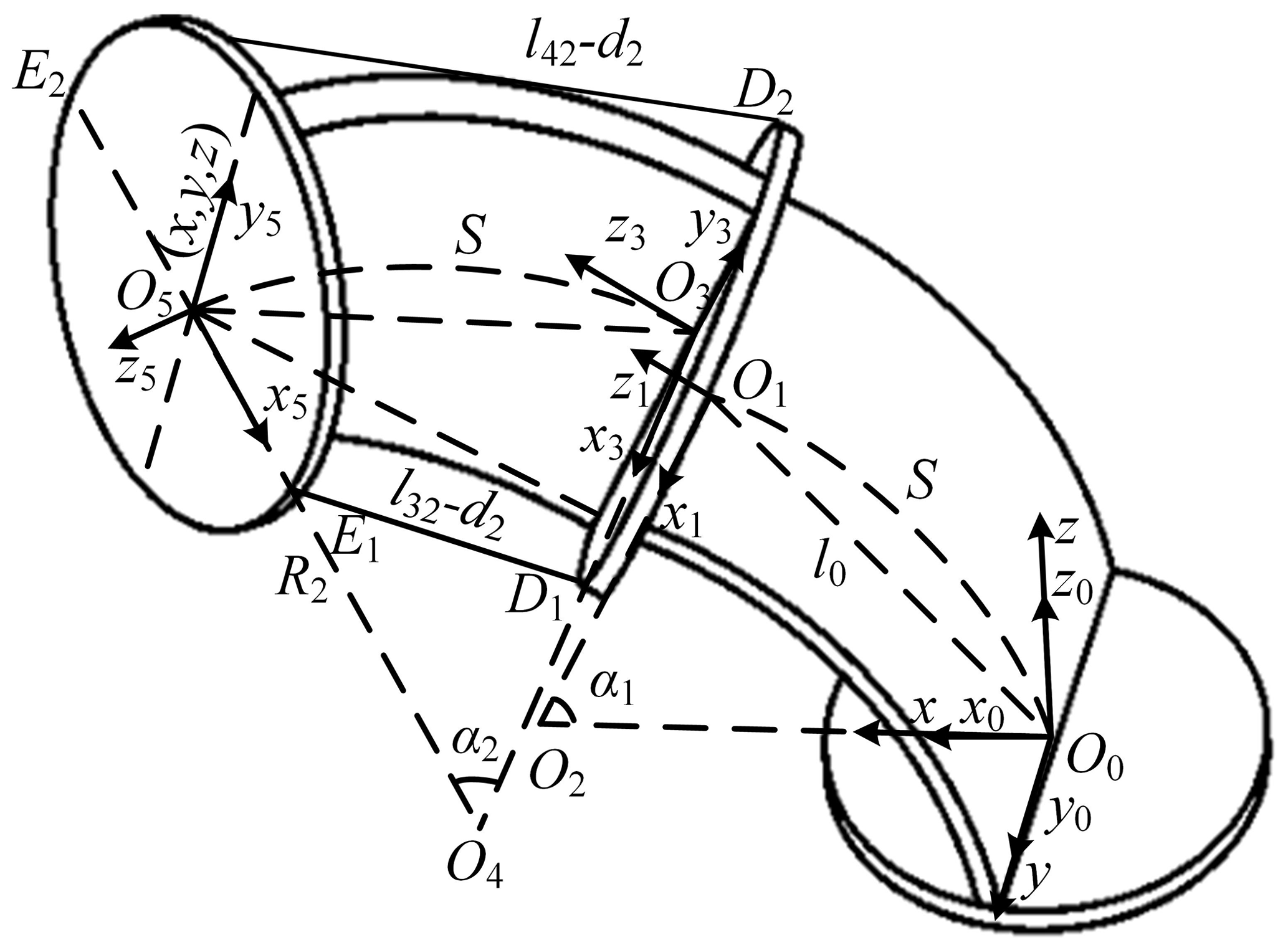
The bending of the second bending section about the y3 axis shown in Fig. 5 is defined as a positive bending, and we get
where l3 and l4 are the total lengths of the two driving cables of the second bending section, and l31 and l41 are a section of the driving cables of the second bending section between the top plane of the lower connector and the top plane of the upper connector of the first bending section.
When α1≠0 and α2≠0, the expression of the tip coordinate of the series unit obtained from the geometry in Fig. 5 is
where x, y, and z represent the tip coordinate of the series unit in the task space, and α1 and α2 represent the bending angles of the first and second bending sections, respectively.
When ,
The bending angle α of the bending curve can be expressed as
where S represents the arc length of the first and second bending sections.
Equations (1), (5), (6), (7), (8), (9), (14), and (15) are substituted into Eqs. (10), (11), and (12), and the tip coordinate of the series unit can be expressed by cable lengths when α1≠0 and α2≠0 as follows:
where , , and .
To replace the cable lengths with the cable length variations, we first get
where Δl1, Δl2, Δl3, and Δl4 are the variations of cables l1, l2, l3, and l4.
Then, when Δl1 and Δl3 are both less than zero, we get the following according to the geometric relationship in Fig. 3:
The shape of each bending section is determined by one cable. Δl2 can be computed by Δl1. According to Eqs. (23) and (24), we use MATLAB software to draw up a relationship graph between Δl1 and Δl2 when α1 is in the range of 0 to 85∘, which is fitted as
Further, we can get the following according to the geometric relationship in Fig. 3:
where Δl0 is the chord length of the first bending section minus the length S of the first elastic piece.
According to Eqs. (23) and (26), we draw up a relationship graph between Δl0 and Δl1 when α1 is in the range of 0 to 85∘, which is fitted as
where Δl31 and Δl41 are the variations of cables 3 and 4 when driving cable 1.
Further, we can get
Similarly, according to Eqs. (29) and (30), the relationship between Δl32 and Δl42 when α2 is in the range of 0 to 85∘ is fitted as
One can then substitute Eqs. (25), (27), (28), (31), (32), and (33) into Eqs. (19), (20), (21), and (22) to obtain the cable lengths l1, l2, l3, and l4 expressed by the cable variations Δl1 and Δl32, which can be put into Eqs. (16), (17), and (18) to get the tip coordinate of the series unit.
3.2 Inverse kinematics
Similarly, in order to obtain the inverse solution of the series unit, we first need to get the inverse solution of the first bending section by using geometric methods. We can get this from the geometry in Fig. 3:
According to Eqs. (7), (8), and (9), we can get
And then we can get
Substituting Eqs. (34), (39), and (40) into Eqs. (37) and (38) yields the cable lengths l3 and l4 as
Substituting and into Eqs. (10), (11), and (12) yields
According to Eq. (44), we use MATLAB to draw up a relationship graph between y and α2 when α2 is in the range of 0 to 85∘, which is fitted as
The relationship between x, y, and α1 is also drawn up according to Eqs. (43) and (45) when α1 and α2 are both in the range of 0 to 85∘, and the fitting equation is obtained as follows:
Substituting , , Eqs.(46), and (47) into Eqs. (35), (36), (41), and (42), one can obtain the lengths of the four cables represented by the tip coordinates of the series unit.
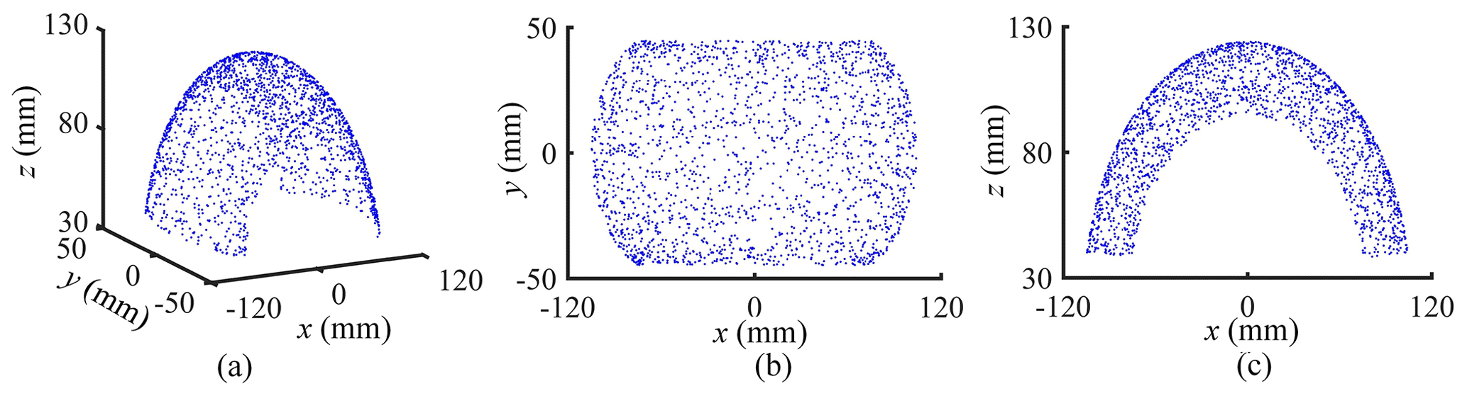
3.3 Workspace of the series unit
The maximum bending angle α of each bending section is limited to 85∘ where it can exhibit good bending characteristics. The physical parameters of the robot are S=50 mm, d1=10 mm, d2=14 mm, and mm. Thus, through the Eqs. (35), (36), (41), and (42), the length ranges of cables l1 and l2 can be obtained, which are both 35.61–75.47 mm, and the length ranges of cables l3 and l4 are both 95.15–135.01 mm. The workspace of the series unit is shown in Fig. 6, which is found using the forward kinematics equations. The x, y, and z are respectively in the range of −104.48 to 104.48 mm, −44.71 to 44.71 mm, and 40.03 to 124 mm.
4.1 Forward kinematics verification
The tip position coordinates of the series unit obtained from the experiment are compared with the theoretical model results to verify the accuracy of the theoretical model. The verification test device of the series unit is shown in Fig. 7. The cable length changes Δl1 and Δl3 can be measured by two hand-operated mobile stands equipped with digital rulers ① and ② having a resolution of 0.01 mm, respectively. The tip coordinates of the series unit can be measured by the other two hand-operated mobile stands equipped with laser locators and digital rulers, and digital rulers ③, ④, and ⑤ are used to record the values of x, y, and z, respectively. First, cables 1 and 3 were tightened. Then, the cable length l1 was reduced by 1.22 mm in turn, and meanwhile the cable length l3 was reduced by a corresponding length which was calculated by combining Eqs. (27) and (28). Further, the cable length l3 was reduced by 1.22 mm in turn. This process performs 20 times, and the bending angle of each bending section reaches the maximum value (85∘).
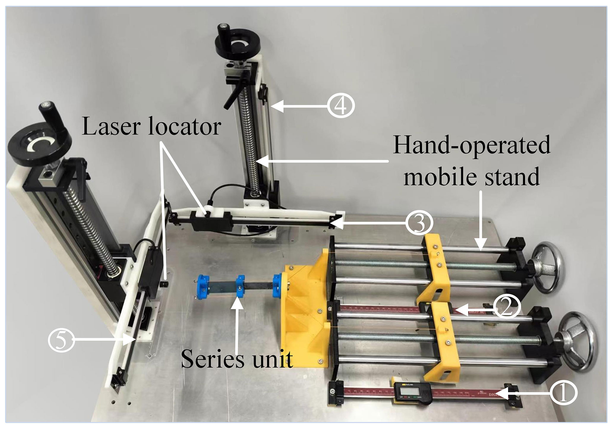
Figure 7The verification test device of the series unit (①, ②, ③, ④, and ⑤ are the numbers of digital rulers).
As shown in Fig. 8, 20 sets of tip position coordinates obtained in this process were compared with the theoretical values. The theoretical values of x andy are generally smaller than the experimental values, and the theoretical values of z are generally larger than the experimental values. This is mainly due to the small deformation of the two elastic sheets in advance caused by the tensioning of cables. The formula is used to express the normalised errors which are shown in Fig. 8d, where P3 and Ps3 represent the experimental and theoretical tip position coordinates, respectively. With the increase of the cable length variation, the normalised errors also increase, but the maximum error does not exceed 1 mm. It shows that when the bending angles of the bending sections are within 85∘, the tip coordinates of the theoretical model are in good agreement with the experimental data. The excellent bending characteristics of the elastic sheet deteriorate as its bending angle becomes larger, and thus the position coordinate errors of the theoretical model with constant curvature increase. However, the model errors are within the desired range, which verifies that the theoretical model has good accuracy.
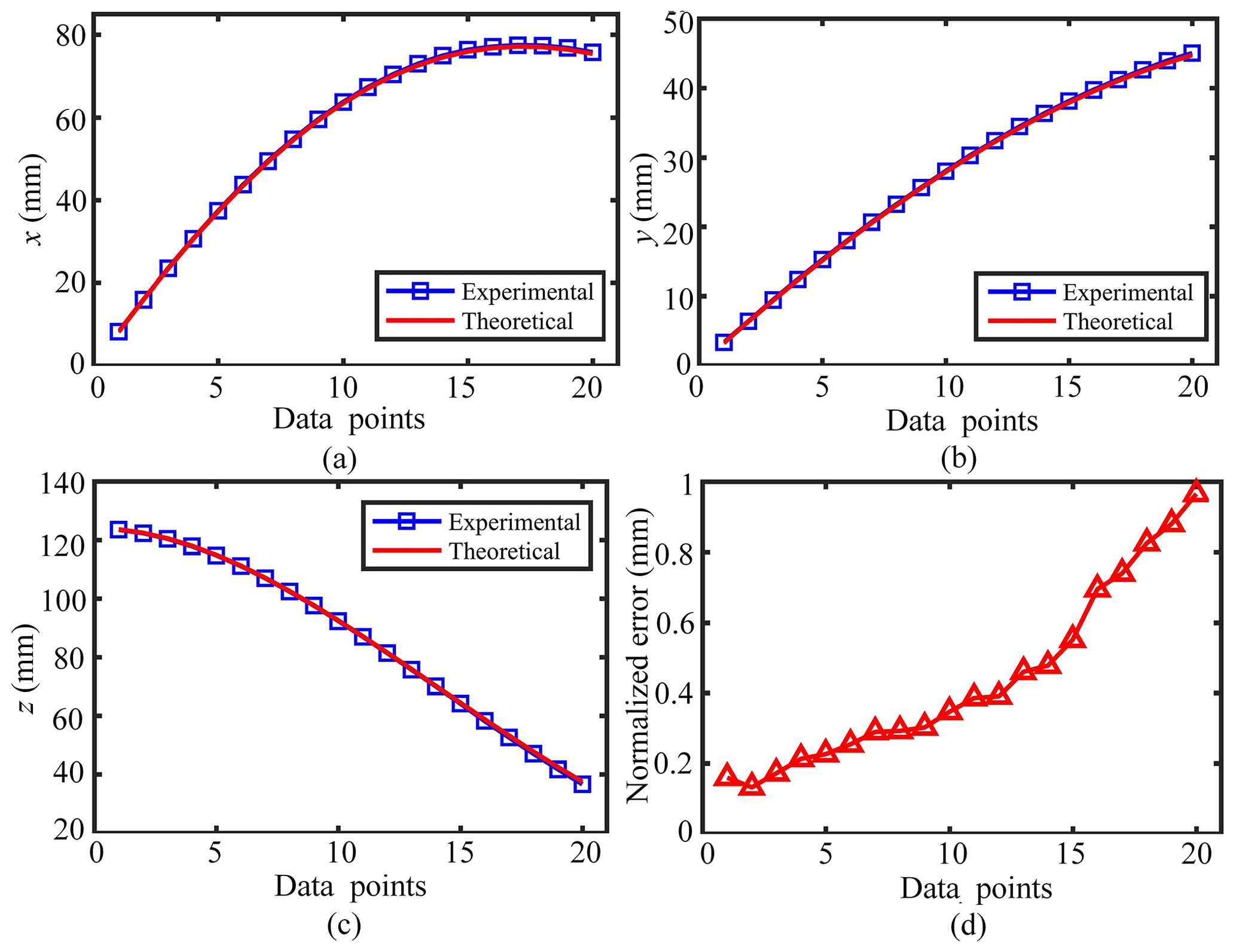
Figure 8(a–c) The experimental tip position coordinates of the series unit at each data point are compared with the theoretical results. (d) The normalised errors at each data point.
4.2 Inverse kinematics verification
The theoretical values of Δl1 and Δl3 are obtained by substituting the above experimental tip position coordinates into inverse kinematics equations. As shown in Fig. 9a and b, the Δl1 and Δl3 results of theory and experiment have a good consistency. The actual length reductions of cables 1 and 3 are generally slightly smaller than the theoretical length reductions when obtaining the same tip coordinates. This trend is more pronounced as the bending angle increases. There are three main reasons for this phenomenon. Firstly, the tip position of the series unit is changed in advance because of the beforehand deformation of the elastic sheets due to the tensioning of the cables. Secondly, the errors of the inverse kinematics model with constant curvature will also increase when the excellent bending characteristics of the elastic sheets deteriorate as their bending angle becomes larger. Thirdly, the theoretical bending angles obtained from the fitting equations are slightly larger, and the deviation increases as the bending angles climb. As a result, the theoretical variations of cable length are also higher. As shown in Fig. 9c and d, the errors of Δl1 and Δl3 are less than 0.38 and 0.32 mm, respectively. The errors of Δl1 are generally larger than those of Δl3 because the fitting errors of α1 are greater than those of α2. In general, the errors of Δl1 and Δl3 are both within the desired ranges, which verifies that the inverse kinematics model has good accuracy.
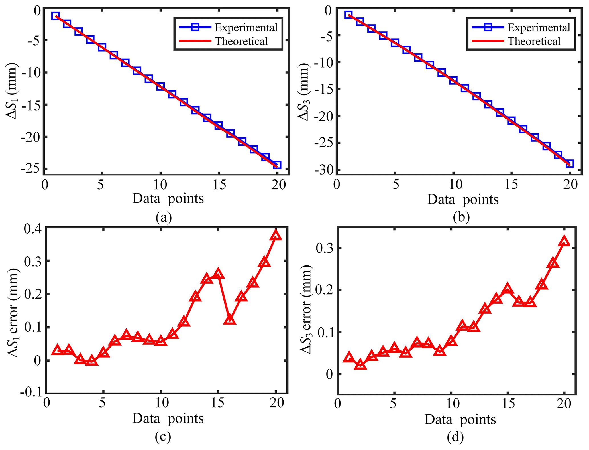
Figure 9(a, b) The experimental values of Δl1 and Δl3 at each data point are compared with the theoretical results. (c, d) The errors of Δl1 and Δl3 at each data point.
The bending coupling of the cruciform continuum robot in different directions is low. The up–down and left–right movements of the tip of the robot can be realised by driving its fourth and third bending sections, respectively, as shown in Fig. 10a. In addition, the cruciform continuum robot has good dexterity, allowing it to easily avoid obstacles such as the ball in Fig. 10b. The cruciform continuum robot can be installed in a mobile vehicle, and its working range and operation ability are improved. Besides this, the robot can be applied for manipulation and exploration. In an example demonstration, we install a suction cup and camera at the tip of the robot, as shown in Fig. 10c. The robot can complete the nucleic acid detection procedure, including grasping the cotton swab, taking a sample, putting the pharyngeal swab into a test tube, and breaking it off. The biggest advantage of using the robot for nucleic acid detection is the natural compliance of the continuum manipulator, which allows the robot to adaptively deform when colliding with the human body or the environment to minimise damage to the patient or the robot itself. The experiment fully demonstrated its advantages of good safety, flexibility, and compliance, and the robot is expected to be applied in practice.
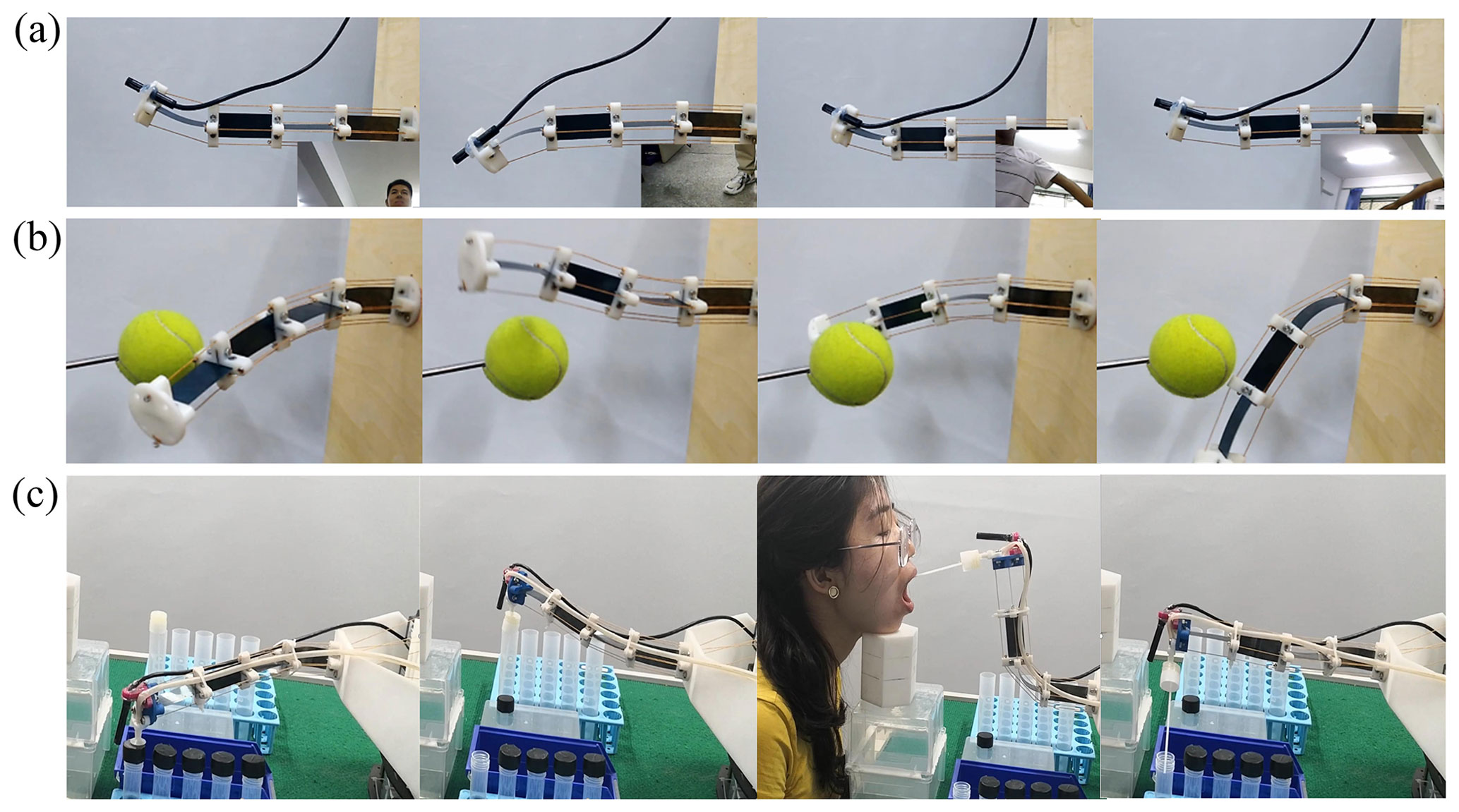
Figure 10(a) The up–down and left–right movements of the tip of the robot are realised by driving its fourth and third bending sections, respectively. (b) The robot moves around a ball flexibly. (c) When the tip of the robot is equipped with a suction cup and a camera, the robot can be used for nucleic acid detection. It finishes the preparatory work, grabs a cotton swab, takes a sample, puts the pharyngeal swab into a test tube, and breaks it off.
One of the research focuses in the field of continuum robotics is to realise the lightweight and dexterity design of continuum robots. Considering the basic structural forms of continuum robots and their equivalent load beam types, this paper proposes a cruciform continuum robot, which is formed by multiple elastic sheets with rectangular beam structures arranged in a cruciform shape. The cruciform layout structure of the rectangular beams enables the bending coupling reduction of the continuum robot in different directions and good bending characteristics in the deformation direction. Meanwhile, this unique structure ensures sufficient bearing capacity in the non-deformation direction and reduces the materials required for robot manufacture. The robot has a mass of 65 g. In terms of length, its average mass per millimetre is 0.255 g, and from its cylindrical envelope volume, its average mass per cubic millimetre is 0.0002 g. This paper presents a new structural design for lightweight dexterous continuum robots. The cruciform continuum robot has good constant curvature characteristics when each bending section has a bending angle smaller than 85∘, which provides a good hardware foundation for its high-precision kinematic modelling. Further, its forward and inverse kinematics models with constant curvature are established using geometric methods, and their accuracy is experimentally verified. The maximum value of the prediction error of the tip position coordinates is less than 1 mm, and the maximum value of the prediction error of the cable length is less than 0.4 mm. In addition, the nucleic acid detection simulation demonstration proves the dexterity and friendly man–machine interaction of the cruciform continuum robot, which is expected to be applied in man–machine interactive fields.
In the future, we will add a protective cover for the continuum robot, and thus the exposed driving cables and elastic backbone will not collide with other objects in the environment. We will further optimise the robot prototype to make it have better operational performance in practical applications. For example, we will make the elastic sheet gradually become thicker from the tip to meet the stress distribution law of the cantilever beam structure. In addition, our future work will mainly focus on the following two aspects. On the one hand, we will continue to create new configurations and achieve the lightweight design of continuum robots. On the other hand, we will develop an ultra-long continuum robot which has more degrees of freedom and a more compact structure.
All the data used in this paper can be obtained upon request from the corresponding author.
ZP and JY conceived the presented idea. ZP established an overall paper research framework and the model. HZ and XZ assisted with the theory. SK and KZ assisted with the experiment. All the authors read and approved the final paper.
The contact author has declared that none of the authors has any competing interests.
Publisher's note: Copernicus Publications remains neutral with regard to jurisdictional claims in published maps and institutional affiliations.
This study has been funded by the National Natural Science Foundation of China (grant nos. U2037202 and 51975505) and the International Cooperative Research and Development Project of Intelligent Fire Fighting Robot (grant no. 19391825D). The authors sincerely thank the editors and reviewers for their insight and comments, which further improved the quality of this paper.
This research has been supported by the National Natural Science Foundation of China (grant nos. U2037202 and 51975505) and the International Cooperative Research and Development Project of Intelligent Fire Fighting Robot (grant no. 19391825D).
This paper was edited by Daniel Condurache and reviewed by two anonymous referees.
Al-Fahaam, H., Nefti-Meziani, S., Theodoridis, T., and Davis, S.: The Design and Mathematical Model of a Novel Variable Stiffness Extensor-Contractor Pneumatic Artificial Muscle, Soft Robot., 5, 576–591, https://doi.org/10.1089/soro.2018.0010, 2018.
Alqumsan, A. A., Khoo, S., and Norton, M.: Robust Control of Continuum Robots Using Cosserat Rod Theory, Mech. Mach. Theory, 131, 48–61, https://doi.org/10.1016/j.mechmachtheory.2018.09.011, 2019.
Bajo, A. and Simaan, N.: Hybrid motion/force control of multi-backbone continuum robots, Int. J. Robot. Res., 35, 422–434, https://doi.org/10.1177/0278364915584806, 2016.
Bamotra, A., Walia, P., Prituja, A. V., and Ren, H.: Layer-Jamming Suction Grippers With Variable Stiffness, J. Mech. Robot., 11, 035003, https://doi.org/10.1115/1.4042630, 2019.
Bieze, T. M., Largilliere, F., Kruszewski, A., Zhang, Z., Merzouki, R., and Duriez, C.: Finite Element Method-Based Kinematics and Closed-Loop Control of Soft, Continuum Manipulators, Soft Robot., 5, 348–364, https://doi.org/10.1089/soro.2017.0079, 2018.
Boyvat, M., Koh, J.-S., and Wood, R. J.: Addressable wireless actuation for multijoint folding robots and devices, Science Robotics, 2, eaan1544, https://doi.org/10.1126/scirobotics.aan1544, 2017.
Braganza, D., Dawson, D. M., Walker, I. D., and Nath, N.: A Neural Network Controller for Continuum Robots, IEEE T. Robot., 23, 1270–1277, https://doi.org/10.1109/TRO.2007.906248, 2007.
Buckingham, R. and Graham, A.: Nuclear snake-arm robots, Ind. Robot, 39, 6–11, https://doi.org/10.1108/01439911211192448, 2012.
Burgner-Kahrs, J., Rucker, D. C., and Choset, H.: Continuum Robots for Medical Applications: A Survey, IEEE T. Robot., 31, 1261–1280, https://doi.org/10.1109/TRO.2015.2489500, 2015.
Childs, J. A. and Rucker, C.: Leveraging Geometry to Enable High-Strength Continuum Robots, Frontiers in Robotics and AI, 8, 629871, https://doi.org/10.3389/frobt.2021.629871, 2021.
Dong, X., Raffles, M., Cobos-Guzman, S., Axinte, D., and Kell, J.: A Novel Continuum Robot Using Twin-Pivot Compliant Joints: Design, Modeling, and Validation, J. Mech. Robot., 8, 021010, https://doi.org/10.1115/1.4031340, 2016.
Godage, I. S., Webster, R. J., and Walker, I. D.: Center-of-Gravity-Based Approach for Modeling Dynamics of Multisection Continuum Arms, IEEE T. Robot., 35, 1097–1108, https://doi.org/10.1109/TRO.2019.2921153, 2019.
Guo, Y., Guo, J., Liu, L., Liu, Y., and Leng, J.: Bioinspired multimodal soft robot driven by a single dielectric elastomer actuator and two flexible electroadhesive feet, Extreme Mechanics Letters, 53, 101720, https://doi.org/10.1016/j.eml.2022.101720, 2022.
Hawkes, E. W., Blumenschein, L. H., Greer, J. D., and Okamura, A. M.: A soft robot that navigates its environment through growth, Sci. Robot., 2, eaan3028, https://doi.org/10.1126/scirobotics.aan3028, 2017.
Hofer, M., Sferrazza, C., and D'Andrea, R.: A Vision-Based Sensing Approach for a Spherical Soft Robotic Arm, Front. Robot. AI, 8, 630935, https://doi.org/10.3389/frobt.2021.630935, 2021.
Jiang, A., Ranzani, T., Gerboni, G., Lekstutyte, L., Althoefer, K., Dasgupta, P., and Nanayakkara, T.: Robotic Granular Jamming: Does the Membrane Matter?, Soft Robot., 1, 192–201, https://doi.org/10.1089/soro.2014.0002, 2014.
Kato, T., Okumura, I., Song, S.-E., Golby, A. J., and Hata, N.: Tendon-Driven Continuum Robot for Endoscopic Surgery: Preclinical Development and Validation of a Tension Propagation Model, IEEE/ASME Transactions on Mechatronics, 20, 2252–2263, https://doi.org/10.1109/TMECH.2014.2372635, 2015.
Kim, Y., Parada, G. A., Liu, S., and Zhao, X.: Ferromagnetic soft continuum robots, Science Robotics, 4, eaax7329, https://doi.org/10.1126/scirobotics.aax7329, 2019.
Krovi, V. and Nie, X.: Design of reconfigurable coupled-serial-chain-based manipulation assistive aids, Robot. Cim.-Int. Manuf., 24, 345–358, https://doi.org/10.1016/j.rcim.2007.01.003, 2008.
Laschi, C., Mazzolai, B., and Cianchetti, M.: Soft robotics: Technologies and systems pushing the boundaries of robot abilities, Science Robotics, 1, eaah3690, https://doi.org/10.1126/scirobotics.aah3690, 2016.
McMahan, W., Jones, B. A., and Walker, I. D.: Design and implementation of a multi-section continuum robot: Air-Octor, in: 2005 IEEE/RSJ International Conference on Intelligent Robots and Systems, Edmonton, AB, Canada, 2–6 August 2005, IEEE, 2578–2585, https://doi.org/10.1109/IROS.2005.1545487, 2005.
Miller-Jackson, T., Sun, Y., Natividad, R., and Yeow, C. H.: Tubular Jamming: A Variable Stiffening Method Toward High-Force Applications with Soft Robotic Components, Soft Robot., 6, 468–482, https://doi.org/10.1089/soro.2018.0084, 2019.
Polygerinos, P., Correll, N., Morin, S. A., Mosadegh, B., and Shepherd, R. F.: Soft Robotics: Review of Fluid-driven Intrinsically Soft Devices; Manufacturing, Sensing, Control, and Applications in Human-robot Interaction: Review of Fluid-driven Intrinsically Soft Robots, Adv. Eng. Mater., 19, e201700016, https://doi.org/10.1002/adem.201700016, 2017.
Qian, X., Chen, Q., Yang, Y., Xu, Y., Li, Z., Wang, Z., Wu, Y., Wei, Y., and Ji, Y.: Untethered Recyclable Tubular Actuators with Versatile Locomotion for Soft Continuum Robots, Adv. Mater., 30, 1801103, https://doi.org/10.1002/adma.201801103, 2018.
Roesthuis, R. J. and Misra, S.: Steering of Multisegment Continuum Manipulators Using Rigid-Link Modeling and FBG-Based Shape Sensing, IEEE T. Robot., 32, 372–382, https://doi.org/10.1109/TRO.2016.2527047, 2016.
Rus, D. and Tolley, M. T.: Design, fabrication and control of soft robots, Nature, 521, 467–475, https://doi.org/10.1038/nature14543, 2015.
Santoso, J. and Onal, C. D.: An Origami Continuum Robot Capable of Precise Motion Through Torsionally Stiff Body and Smooth Inverse Kinematics, Soft Robotics, 8, 371–386, https://doi.org/10.1089/soro.2020.0026, 2021.
Till, J. and Rucker, D. C.: Elastic Stability of Cosserat Rods and Parallel Continuum Robots, IEEE T. Robot., 33, 718–733, https://doi.org/10.1109/TRO.2017.2664879, 2017.
Tonapi, M. M., Godage, I. S., and Walker, I. D.: Next generation rope-like robot for in-space inspection, in: 2014 IEEE Aerospace Conference, Big Sky, MT, USA, 1–8 March 2014, IEEE, 1–13, https://doi.org/10.1109/AERO.2014.6836183, 2014.
Tsukagoshi, H., Kitagawa, A., and Segawa, M.: Active Hose: an artificial elephant's nose with maneuverability for rescue operation, in: Proceedings 2001 ICRA. IEEE International Conference on Robotics and Automation (Cat. No.01CH37164), Seoul, South Korea, 21–26 May 2001, IEEE, 2454–2459, https://doi.org/10.1109/ROBOT.2001.932991, 2001.
Wang, L. and Simaan, N.: Geometric Calibration of Continuum Robots: Joint Space and Equilibrium Shape Deviations, IEEE T. Robot., 35, 387–402, https://doi.org/10.1109/TRO.2018.2881049, 2019.
Webster, R. J. and Jones, B. A.: Design and Kinematic Modeling of Constant Curvature Continuum Robots: A Review, Int. J. Robot. Res., 29, 1661–1683, https://doi.org/10.1177/0278364910368147, 2010.
Yang, G.-Z., Bellingham, J., Dupont, P. E., Fischer, P., Floridi, L., Full, R., Jacobstein, N., Kumar, V., McNutt, M., Merrifield, R., Nelson, B. J., Scassellati, B., Taddeo, M., Taylor, R., Veloso, M., Wang, Z. L., and Wood, R.: The grand challenges of Science Robotics, Science Robotics, 3, eaar7650, https://doi.org/10.1126/scirobotics.aar7650, 2018.
Yarbasi, E. Y. and Samur, E.: Design and evaluation of a continuum robot with extendable balloons, Mech. Sci., 9, 51–60, https://doi.org/10.5194/ms-9-51-2018, 2018.
Yoshida, S., Morimoto, Y., Zheng, L., Onoe, H., and Takeuchi, S.: Multipoint Bending and Shape Retention of a Pneumatic Bending Actuator by a Variable Stiffness Endoskeleton, Soft Robot., 5, 718–725, https://doi.org/10.1089/soro.2017.0145, 2018.
Yu, H.-J., Yang, W.-L., Yang, Z.-X., Dong, W., Du, Z.-J., and Yan, Z.-Y.: Hysteresis analysis of a notched continuum manipulator driven by tendon, Mech. Sci., 9, 211–219, https://doi.org/10.5194/ms-9-211-2018, 2018.
Yuan, H., Chiu, P. W. Y., and Li, Z.: Shape-Reconstruction-Based Force Sensing Method for Continuum Surgical Robots With Large Deformation, IEEE Robot. Autom. Lett., 2, 1972–1979, https://doi.org/10.1109/LRA.2017.2716444, 2017.
Zhang, T., Yang, L., Yang, X., Tan, R., Lu, H., and Shen, Y.: Millimeter-Scale Soft Continuum Robots for Large-Angle and High-Precision Manipulation by Hybrid Actuation, Advanced Intelligent Systems, 3, 2000189, https://doi.org/10.1002/aisy.202000189, 2021.
Zhang, Y., Zhang, N., Hingorani, H., Ding, N., Wang, D., Yuan, C., Zhang, B., Gu, G., and Ge, Q.: Fast-Response, Stiffness-Tunable Soft Actuator by Hybrid Multimaterial 3D Printing, Adv. Funct. Mater., 29, 1806698, https://doi.org/10.1002/adfm.201806698, 2019.
Zhao, Y., Song, X., Zhang, X., and Lu, X.: A Hyper-redundant Elephant's Trunk Robot with an Open Structure: Design, Kinematics, Control and Prototype, Chin. J. Mech. Eng., 33, 96, https://doi.org/10.1186/s10033-020-00509-4, 2020.
Zhu, J., Lyu, L., Xu, Y., Liang, H., Zhang, X., Ding, H., and Wu, Z.: Intelligent Soft Surgical Robots for Next-Generation Minimally Invasive Surgery, Advanced Intelligent Systems, 3, 2100011, https://doi.org/10.1002/aisy.202100011, 2021.