the Creative Commons Attribution 4.0 License.
the Creative Commons Attribution 4.0 License.
 | 24 Feb 2023
Obstacle-avoidance path planning based on the improved artificial potential field for a 5 degrees of freedom bending robot
Kai Cai
Fengyu Xu
Path planning is a key technique used in the operation of bending robots. In this paper, an obstacle-avoidance path-planning method of a 5 degrees of freedom (5 DOF) bending robot based on improved artificial potential field is proposed. Firstly, a connecting-rod coordinate system of the 5 DOF Cartesian bending robot is established to determine an equation of motion trajectory of the bending robot. Secondly, in view of the problem of the local minimum in the artificial potential field (APF) method and the failure of path planning, an improved APF path-planning method based on a rapidly exploring random tree (RRT) algorithm is proposed, which reduces the length of the path and enhances path smoothness. Finally, through simulation and obstacle-avoidance experiments on the path of a mechanical arm, effective path planning based on the improved APF method is verified. The experimental results show that the proposed path-planning method can plan an optimal path and meet the technical requirements of bending robot operations.
- Article
(4158 KB) - Full-text XML
- BibTeX
- EndNote


In the industrial production field, bending robots replace human labor in bending operations, which greatly improves working efficiency and machining quality. Path planning in the machining process is a key technical link in the performance delivery of bending robots. Its task is to find a continuous path from the starting point to the target point in the set area and avoid obstacles under the optimal or quasi-optimal performance index (Akbaripour and Masehian, 2017; Stentz, 1994).
According to the degree of environmental information, the path-planning methods of mobile robots are usually divided into global path planning and local path planning. Global path planning is based on the known global obstacle map information and uses various optimization algorithms to obtain the global optimal path, but it has some disadvantages such as large computation, low search efficiency, and slow convergence speed. Local path planning can acquire the information of the current position and the local obstacle in real time according to its own sensors, so as to obtain the optimal path from the starting point to the target point, but it is easy to fall into the local optimal solution.
Environment modeling and path search are two important issues in global path planning. Global path-planning methods include the visibility graph, A∗ algorithm, D∗ algorithm, and artificial potential field (APF) (Shao et al., 2019; Wang et al., 2019; Rasekhipour et al., 2016). Other global path-planning methods are intelligent optimization algorithms, such as genetic algorithm and particle swarm optimization (Korayem et al., 2016; Kim and Lee, 2015). Using a differential evolution algorithm, Das et al. (2018) propose a method of energy-efficient path planning that can be applied to an industrial robot arm in a workspace containing multiple obstacles. A suitable cost function is used to track the optimal path between initial and final configurations of the robot arm joints.
For industrial robots, exploring in an unknown environment is still a challenging task. In terms of perception and positioning of obstacles, Gala et al. (2018) and Gala and Sun (2019) propose a three-dimensional sound source localization technology based on a self-rotational two-microphone array. It can estimate the position of a stationary sound source in a spherical coordinate system. Filipenko and Afanasyev (2018) compare various simultaneous localization and mapping (SLAM) systems of mobile robots in an indoor environment. The advantages and disadvantages of each SLAM system in different application scenarios are analyzed. Zheng (2019) introduces a new method to investigate the trajectory planning for the multiple degrees of freedom (MDOF) robot in improving accuracy and stability. Fan et al. (2020) present a concise path-planning method for an autonomous underwater vehicle (AUV) based on an improved artificial potential field (APF) method, which considers the spatial location and direction of the velocity of the moving objects. Cong et al. (2020) present a bidirectional fast extended random tree algorithm rapidly exploring random tree connect (RRT) to complete the dual-arm path planning under the planning framework of “MoveIt”.
Considering a safe distance between an end effector of a robot and obstacles to avoid collision, Lai et al. (2017) presented an obstacle-avoidance method for a mechanical arm based on non-uniform rational B-spline curves. Li et al. (2022) proposed an improved A∗ algorithm by a bidirectional alternating search strategy for mobile robots path planning. Nishi and Mori (2018) proposed a motion planning method based on the potential field, which saves energy and optimizes picking points of the workpieces. Contreras-Cruz et al. (2015) proposed a robust algorithm based on meta-heuristic methods to generate a path composed of forwarding motion and rotation. By adding a singular value decomposition method to optimize the measurement of operability, Ahmed et al. (2022) proposed an integrated path-planning algorithm based on the deformation of thin metal plates. Kovács et al. (2016) presented a mobile robot path-planning method using animal motion attributes, and it was capable of online navigation in dynamic environments.
In terms of path planning based on machine learning, Zhou et al. (2022) developed an improved lazy probabilistic-roadmap-algorithm-based online collision-free path-planning method for arc welding robots. Zhuang et al. (2019) proposed an RRT algorithm with a variable step length for path planning of a dual-arm robot, which improved search efficiency and shortened the time required for path planning. Yu et al. (2017) proposed a task-oriented simulation system of a mechanical arm based on a recurrent neural network and obtained a mapping trajectory between angles of joints of the robot arm. By a dynamic fuzzy neural network algorithm, Han et al. (2015) obtained inverse kinematic parameters of a robot, which improved the calculation accuracy and efficiency. Jun et al. (2017) proposed an improved spline interpolation method based on spline functions and genetic algorithms, which solved the problems of complex workload and inflexible operation in path planning. Wang and Wan (2015) used the improved quintic polynomial interpolation method in a joint space. Sun et al. (2017) presented an improved A∗ algorithm for global path planning and divided the planned path according to a small step length, which reduced the length and turning angle of the path. Li et al. (2017) proposed a trajectory planning method for sprawling robots inspired by a trotting animal and offered references to the trajectory planning of robots.
In the path-planning algorithms for obstacle avoidance, it is common to use the APF method to abstract details pertaining to the actual space. In reference to this, Cheng et al. (2019), based on the task of path planning of a mobile robot, improved the traditional A∗ algorithm and APF method to shorten the driving path of the mobile robot. It solved the problem of path-planning failures in the case of a local minimum being located. To improve the global search ability of path planning for a mobile robot, the improved APF and ant colony algorithm (ACA) under a global static environment was proposed in reference to Wang et al. (2018), which allowed planning of the optimal path, albeit with complex computational processing.
Path smoothing is an important part of path planning; the path obtained by the traditional planning algorithms is usually a sequence of multiple line segments and is a non-smooth curve, which readily causes discontinuous motion of a robot, while a smooth path can ensure continuous motion. In this paper, an improved APF-based path-planning method based on the idea of RRT is proposed, which reduces the length of the path and makes the path smoother.
The remainder of this paper is organized as follows. In Sect. 2, the kinematics of the 5 DOF bending robot is analyzed. In Sect. 3, trajectory planning of the robot based on the improved APF method is introduced. Simulation and experimental results are presented and discussed in Sect. 4, respectively. Section 5 concludes the paper.
2.1 Establishment of the coordinate system of the 5 DOF robot
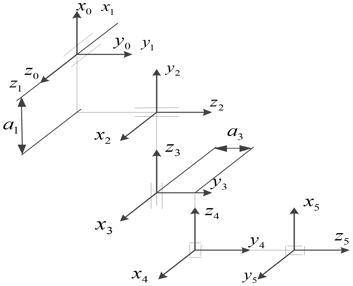
For a bending robot, it is necessary to find feasible solutions in high-dimensional configuration space. Therefore, a spatial coordinate system needs to be established for the bending robot to obtain the spatial position of its end effector, thus turning path planning into a constrained optimization problem (Ratiu and Prichici, 2017). A mechanical arm of the bending robot is a multi-DOF structure with multiple rigid bodies connected in series. To describe changes in the relative position between adjacent connecting rods, a coordinate system is established for each connecting rod, thus obtaining position coordinates of the end effector of the mechanical arm in a three-dimensional (3-d) coordinate system.
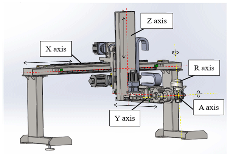
During the motion of the mechanical arm, the coordinate system of the base remains fixed, and the relative positions of other connecting-rod coordinate systems are ascertained based thereon. The 5 DOF Cartesian bending robot consists of three moving joints and two rotating joints connected in series. For three joints moving in a straight line, the Z axis denotes the direction of movement of each joint. For the two rotating joints, the Z axis represents the rotational direction of each joint. The first three moving axes determine the position of the end effector, and the last two rotation axes determine the pose of the end effector. The X axis denotes the Denavit–Hartenberg (D–H) modeling rule, and the Y axis is determined according to the right-hand rule; therefore, the established connecting-rod coordinate system of the 5 DOF Cartesian mechanical arm is shown in Fig. 1. The established coordinate system of the 5 DOF Cartesian bending robot is shown in Fig. 2.
2.2 Kinematic analysis of the bending robot
This bending robot, with 5 DOF, cooperates with a computer numerical control (CNC) bending machine to bend a sheet-metal part. An end device of the robot clamps the sheet-metal part. After the host computer sends the bending command, the sliding blocks of the bending machine start to operate from the top dead center. When the tool tip of the upper dies contacts the materials to be bent, the bending machine sends the bending command to the robot. According to the planned path algorithm, the robot controls the mechanical arm to follow the bending process. In the motion-following process for bending the mechanical arm, the Y axis, Z axis, and A-rotation axis of the bending robot need to follow the bending of the sheet-metal part. The coordinate system of the robot following the bending machine is shown in Fig. 3.
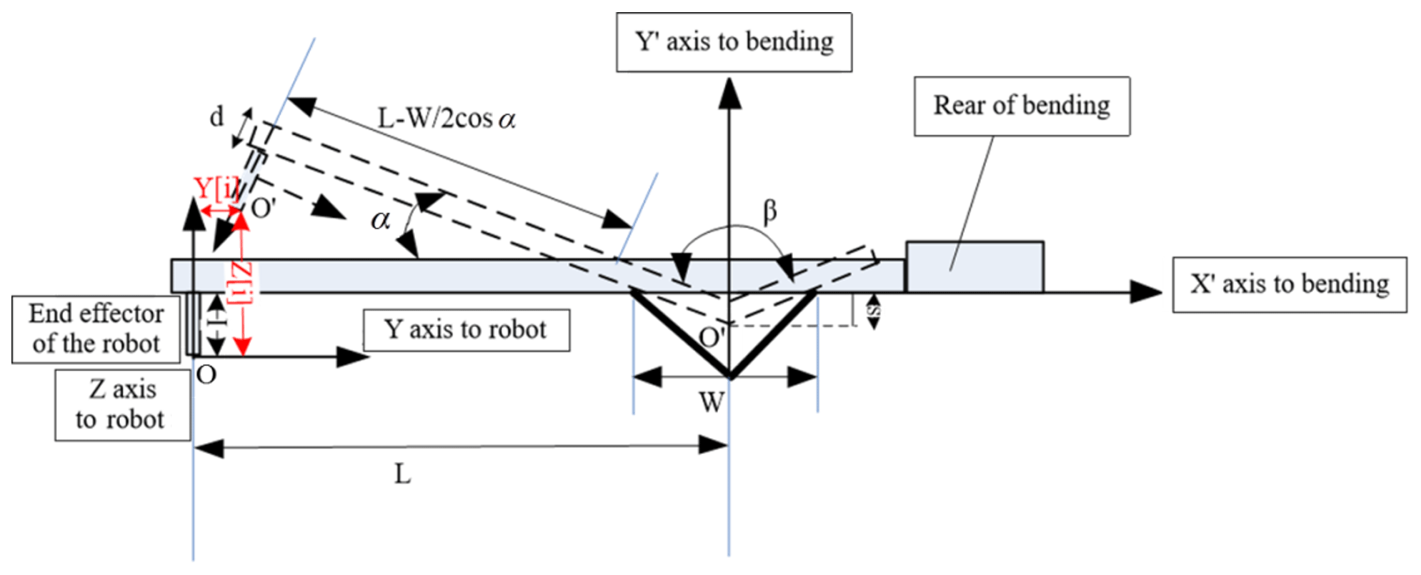
In Fig. 3, the coordinate system XOY is established with the end effector of the bending robot at the center, while the coordinate system is a basic coordinate system of the bending machine. I, d, and α indicate the thickness of the end effector of the robot, the thickness of the sheet-metal part, and the angle between the sheet-metal part clamped by the end effector of the mechanical arm and the X axis during the bending operation, respectively. L, β, W, and S represent the horizontal distance from the reference origin O of the sheet-metal part to the center O′ of a V-shaped groove, the angle of the sheet-metal part to be bent, the width of the V-shaped groove in the lower die, and the bending depth of the sheet-metal part, respectively. I, d, and L are constants, while α varies. When calculating the bending about the Y and Z axes and the A-rotation axis of the bending robot following the bending of sheet-metal part, it is only necessary to calculate the kinematic equations pertaining to the Y and Z axes of the robot relative to the angle α.
The angle between the sheet-metal part clamped by the end effector of the mechanical arm and the X axis shows the following relationship with bending depth S and width W of the V-shaped groove (known constants):
The relationship between α and the angle β of the sheet-metal part to be bent is expressed as follows:
The bending depth S is given by
Similarly, according to the geometric relationship of moving coordinates in Fig. 3, the displacement of point O in the coordinate system of the robot's end effector along the Z axis is obtained as follows:
The displacement of point `O in the coordinate system of the robot's end effector along the Y axis is
Bending equations about the Y and Z axes of the robot with respect to angle α are
Based on the above bending process, the motion path of the end effector of the bending robot can be determined through calculation. In the joint space and the Cartesian space, the bending trajectory of the robot can be separately planned.
3.1 Artificial potential field (APF) method
The APF method is a virtual force method that constructs the fields of attractive force and repulsive force acting together around the objective position and obstacles by introducing a potential field function to describe the workspace of the robot (Orozco-Rosas et al., 2019). The robot is subject to the joint action of the attractive force generated at the objective point and the repulsive force generated by obstacles in the virtual potential field, and the optimal collision-free path is planned by searching the descent direction of the potential function. The APF method, with its high computational efficiency, can achieve real-time path planning and trajectory smoothing; however, it is often trapped in local optima, preventing path planning (Wan et al., 2019; Kovács et al., 2016).
The energy applied to the robot at a certain point in the trajectory can be expressed as
where U(i) indicates the virtual potential field; and Uatt(i) and Urep(i) represent virtual potential fields of the attractive and repulsive, forces, respectively.
If the bending robot moves in a two-dimensional finite space and its position in the motion space is Pi, the potential function of attractive force between the robot and the objective point is expressed as follows:
where ka and |Pi−Pg| denote the scale factor of attractive force and the distance between the current position and the objective position of the robot, respectively.
The potential function of the repulsive force between the bending robot and obstacles is written as follows:
where kr, di, and d0 indicate the scale factor of the repulsive force, the distance between the robot and obstacles, and the radius of influence of the potential field of the repulsive force of obstacles.
When the negative gradient energy in the potential fields of attractive and repulsive forces acts on the robot, the resultant force on the robot is expressed as follows:
where ∇U(i) represents the gradient of the potential field at the point i.
The attractive and repulsive forces applied to the robot can be separately expressed as follows:
The APF method searches for the optimal solution by simulating the energy field, but there are two special cases: one is that when the objective point is within the influencing range of the repulsive force of obstacles, the repulsive force will be very large and the attractive force is relatively small, which makes the objective point unreachable. The other one is that when the robot is in a straight line with the objective point and obstacles, or it encounters U-shaped obstacles during motion, it will be trapped in a local minimum.
In view of the above shortcomings of the APF method, a new potential field function is constructed for improvement, based on the idea of the RRT algorithm when the local potential model conflicts with the global one during the path selection of the robot.
3.2 Improved APF method based on the RRT algorithm
The RRT algorithm is a search algorithm based on a tree structure. It is a planning algorithm that extends outward into a tree structure from the initial point and randomly samples points in the planning space to determine the next direction of extension, thus realizing rapid path planning. Characterized by the advantages of avoiding the physical modeling and mathematical modeling of the objective space, quickly expanding to explore the feasible region in the space, and providing efficient execution, the method has been widely used.
The main idea of the improved APF-based path-planning method based on the RRT algorithm is to improve the APF method with the random extension and search characteristics in order to avoid local minima. When falling into the local minimum, the RRT algorithm is used to generate uniform numbers of root nodes around obstacles, and then the components of attractive and repulsive forces are applied to the root nodes to generate a local random tree near the local minimum. Under the guidance of components of attractive and repulsive forces in the APF, the random tree grows to the objective point, thus solving the problem, such as that associated with an unreachable objective point and local minima found during motion planning.
-
Search process using the RRT algorithm.
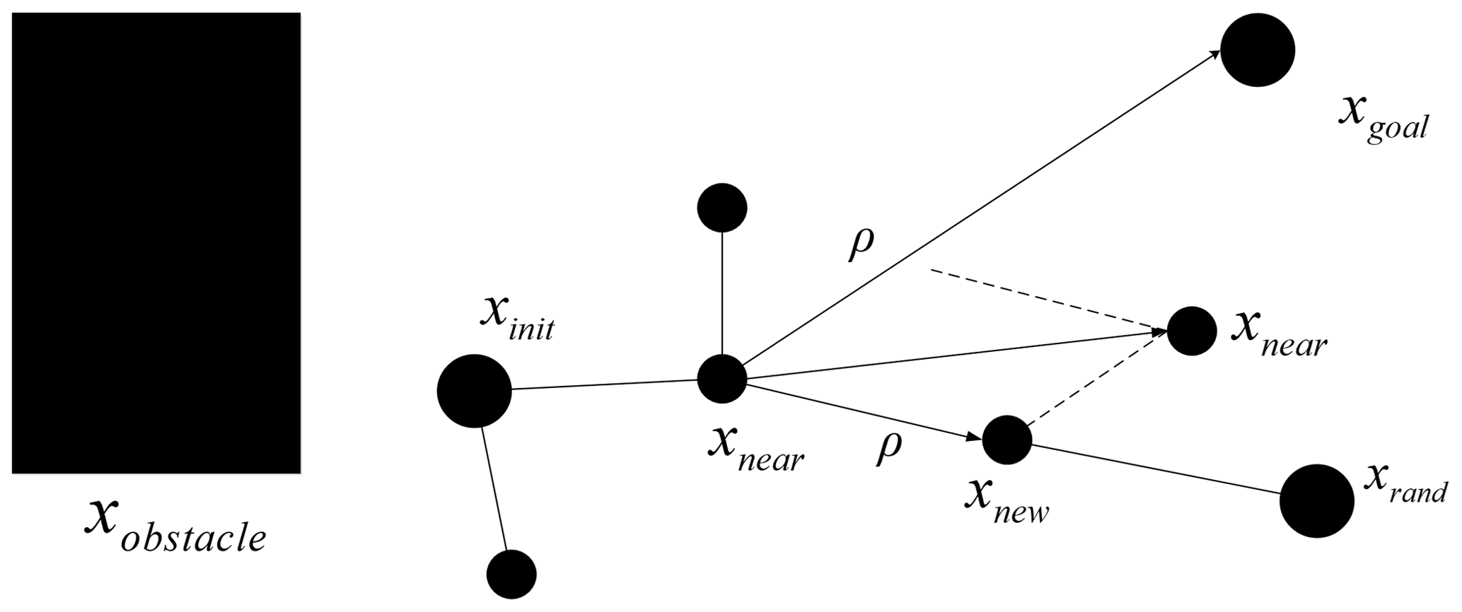
The specific search process using the RRT algorithm is as follows: an initial point is selected in the environment, which is recorded as a root node xinit of the random tree. By searching for the free space, a random sampling point xrand is selected. If xrand is not in the region with obstacles, xinit and xrand are connected to obtain a line L. If the whole line L is not in the region with obstacles, a new node xnew is generated along line L from xinit to xrand according to a certain step length ρ. In this way, the simplest tree is formed by xinit, xnew, and their connection. By selecting node xnear nearest the random sampling point xrand, they are connected, and a new node xnew is generated from xnear at a certain step length ρ. If there is no collision with obstacles during extension from xnear to xnew, a random tree is generated by adding this new node xnew into the random tree. When sub-nodes in the random tree contain the objective point xgoal, a path from the initial point xinit to the objective point xgoal can be generated in the random tree. If collision occurs, this extension is canceled. A schematic representation of the path search in a space containing obstacles using the RRT algorithm is displayed in Fig. 4.
-
Extension of the RRT algorithm by increasing the component of attractive force.
The component of attractive force is added to the RRT algorithm to guide the local random tree to grow towards the objective point, and a schematic diagram of the extension is shown in Fig. 5. The idea is to add an objective function G(n) of attractive force to each node n in the random tree (node n represents the nth node xnew as the random tree extends outward from the initial point xinit); the objective function of attractive force can be expressed as follows:
where ρ and ka indicate the step length and scale factor of attractive force, respectively; and ∥xgoal−xnear∥ represents the absolute value of the geometric distance between node n and the objective point xnear.
The RRT algorithm of a new node xnew can be expressed by the following equation:
The equation for generating a new node after introducing the component of attractive force into the RRT algorithm is shown as follows:
In this way, the points in the random tree can search for and grow to the objective direction in the free space under the action of the component of attractive force, thus avoiding the problem that the objective point is unreachable by the robot.
-
Extension of the RRT algorithm by increasing the component of repulsive force.
The component of repulsive force is added to the RRT algorithm to guide the local random tree to grow away from the obstacles. The extension diagram is demonstrated in Fig. 6. The core idea is to add a function T(n) of repulsive force of obstacles into each node n in the random tree, where node n represents the nth node xnew as the random tree extends outwards from the initial point xinit. The function of the repulsive force of obstacles can be expressed as follows:
where ρ and kr denote the step length and scale factor applied to the repulsive force, respectively; pn denotes the shortest distance from the node to obstacles; and p0 and xobstacle denote the influence range of repulsive force of obstacles on the node and the position vector of obstacles.
The RRT algorithm of the new node xnew can be expressed by the following equation:
The equation for generating a new node after introducing the component of repulsive force into the RRT algorithm is given by
In this way, under the action of the component of repulsive force, the points in the random tree seek and grow, in a direction leading away from obstacles in the free space, so that the robot can escape from the local minimum and reach its objective.

3.3 Implementation of path planning of the robot based on the improved APF method
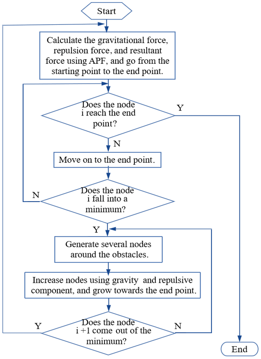
The main idea of path planning of the robot using the improved APF method is summarized as follows: firstly, the APF method is used for path planning in the workspace of a robot. When the motion path falls to a local minimum or the objective point is unreachable, the RRT algorithm is used to optimize the local optimal solution and forces it out of the region of oscillation. When the robot escapes from the local minimum, it returns to path planning using the APF method. The path-planning process of the robot is illustrated in Fig. 7.
The specific implementation steps for path planning of the robot based on the APF method are presented as follows:
- Step 1.
-
The APF method is used to establish a virtual potential field in the workspace. The attractive, repulsive, and resultant forces of the potential field are calculated, respectively, and path planning is conducted.
- Step 2.
-
The robot moves to its objective under the guidance of forces in the potential field. If the objective is unreachable, or the algorithm falls into a local minimum during the motion of the robot, Step 3 is performed. Otherwise Step 4 is executed.
- Step 3.
-
The RRT algorithm is utilized to detect and search for obstacles in the space. By taking the minimum point as a root node, a search structure in the form of a tree is generated until the robot escapes from the region of oscillation.
- Step 4.
-
The robot returns to the potential field and continues to move towards its objective.
- Step 5.
-
Check whether the robot has reached its objective; if it has not, the algorithm returns to Step 2, and if it has, the task of path planning ends.
The main characteristics of the improved APF algorithm are shown as follows:
-
The proposed algorithm is simple and implemented in a small search space. By improving the traditional potential field function and searching for the path which escapes only near the local minimum using the RRT algorithm, the optimal path can be rapidly found. In this way, the time taken to pass an obstacle is reduced, the probability of convergence of the algorithm is increased, and the planning time is shortened.
-
The algorithm is highly robust. Compared with algorithms such as neural networks and genetic algorithms, the APF function can avoid the singularity of the robot and improve the smoothness of the path.
The proposed path-planning method of robots based on the improved APF method is able to plan a realizable, collision-free motion path that does not fall into the local optimum according to the positions of the initial point, objective point, and obstacles. It is applied to the bending operation of a bending robot.
4.1 Simulation analysis of the algorithm
In the workspace of the bending robot, by taking the position where the X axis of the mechanical arm moves to the far left as the origin, three obstacles of different shapes are established. Their boundary coordinates can be seen in Fig. 8. The schematic diagram of the mechanical arm moving from the initial point Q (50 cm, 350 cm) to the end-point Z (400 cm, 120 cm) is also illustrated in Fig. 8.

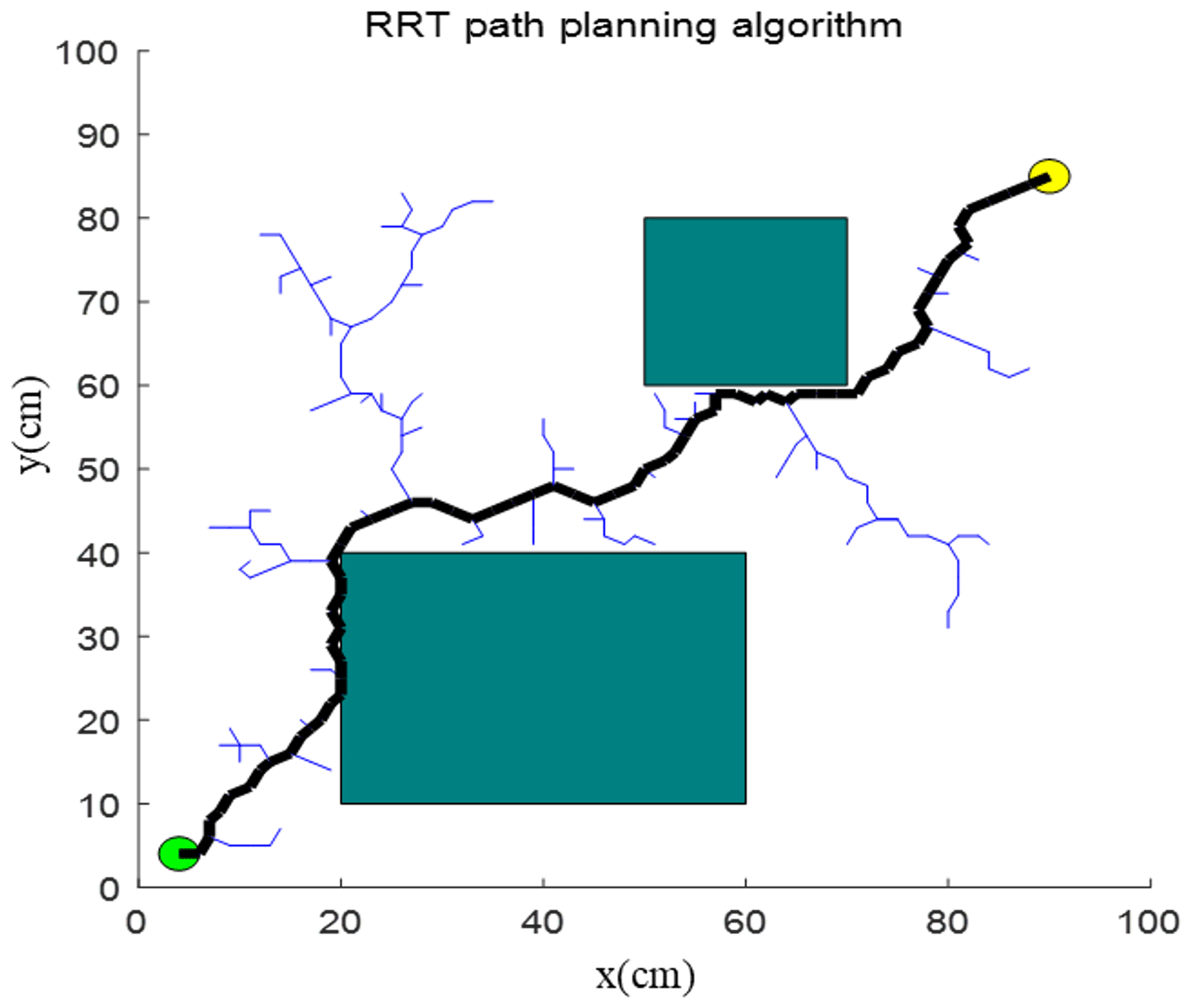
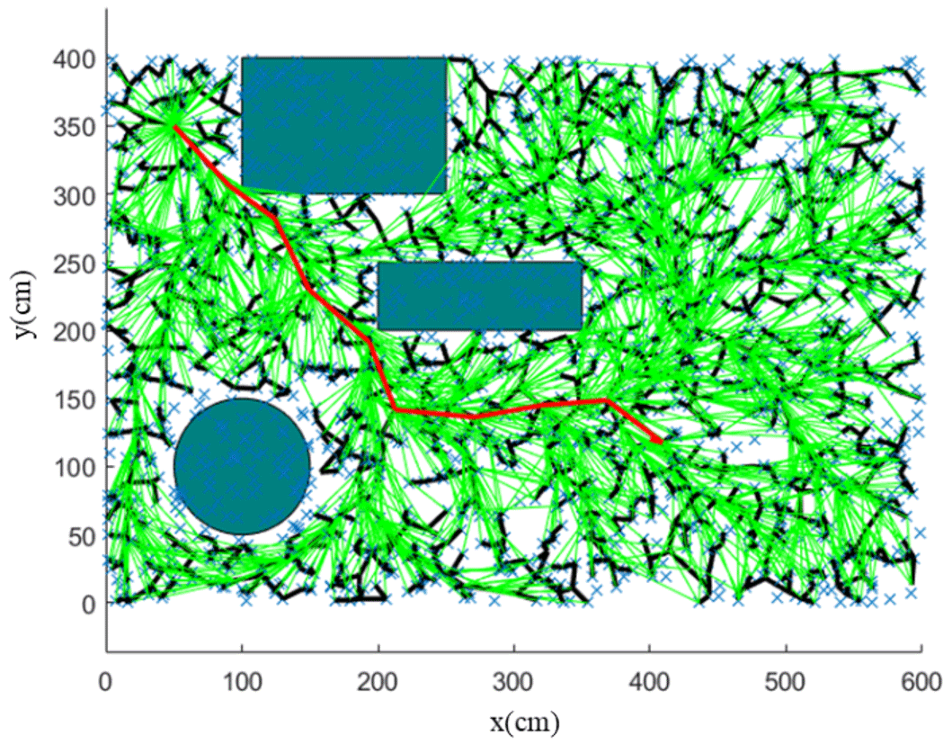
By using the RRT algorithm, the path of the mechanical arm moving from initial point Q (50 cm, 350 cm) to the end point Z (400 cm, 120 cm) is simulated using MATLAB™ (Fig. 9). The parameters of the improved APF method are generally obtained according to the empirical method, simulation result, and experimental environment. The parameter values are set as the step length ρ= 0.5, the scale factor of attractive force ka=1, and the repulsive force of attractive force kr= 50. The simulation results demonstrate that the motion path planned by the RRT algorithm contains turning points, thus increasing the optimization path, making the moving process unsmoothed, and requiring more time for computation.
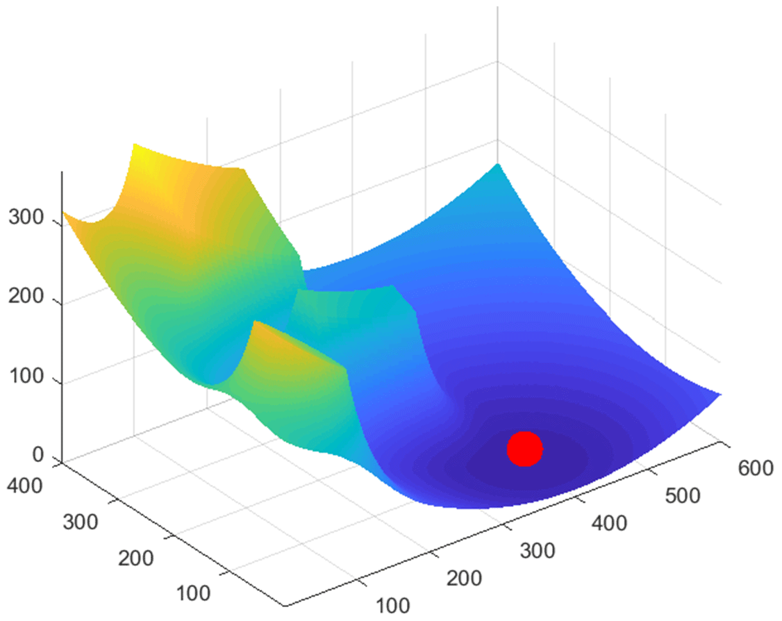
In the same workspace, the improved APF method is simulated. The APF is constructed for the obstacles in the above space, and the potential field of attractive force at the objective point and potential field of repulsive force generated by obstacles are illustrated in Fig. 10. The resultant potential field of the obstacles and the objective point in the motion space is displayed in Fig. 11.


The trajectory of the robot, from the initial point to the end point, is shown in Fig. 12; the path generated by the improved APF algorithm meets the requirements of obstacle avoidance and is smooth, avoiding local minima.
Table 1 lists the length of the optimal path, completion time, and accuracy of obtaining the optimal path by performing 20 simulations of path planning using the RRT algorithm, APF algorithm, and improved APF algorithm.
Table 1Performance comparison of path-planning algorithms in the simulation environment.
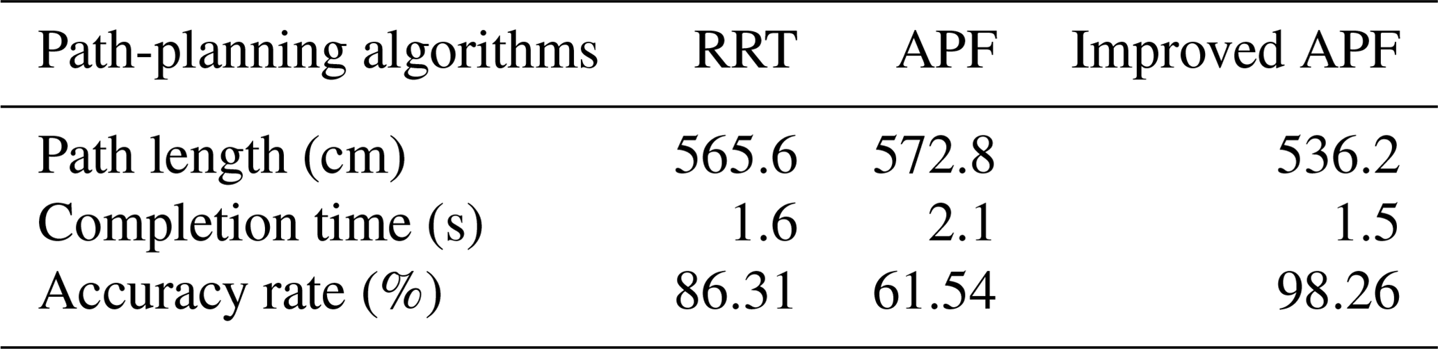
Therefore, integrating the RRT algorithm into the improved APF can overcome the shortcomings of being unable to escape the trap of a local minimum. When the motion planning of the algorithm falls to a local minimum, the local random tree generated by the RRT algorithm guides the robot to continue the process of moving towards the objective point to obtain the optimal planning path. At the same time, the problems of an unsmoothed path planning and the long planning time needed in the RRT algorithm are optimized, thus accelerating the overall path-planning process.
4.2 Obstacle-avoidance path-planning experiment of the robot
To verify the obstacle-avoidance planning ability of the robot based on the improved APF method, obstacles are set in an actual working environment to assess the effectiveness of obstacle avoidance of the robot and the optimality of the path.
In the experiment, the position parameters of the obstacles are established: two cartons, whose size is 400 mm × 300 mm × 280 mm (length × width × height), are selected as obstacles at central coordinates of (−100 mm, −900 mm, −260 mm) and (825 mm, 100 mm, −260 mm). The actual scene of the robot obstacle-avoidance experiment is shown in Fig. 13.

Figure 13The obstacle-avoidance process of the robot arm: (a) the starting state, (b) the obstacle-avoidance state, and (c) the ending state.
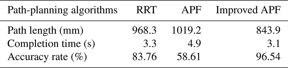
Table 2Performance comparison of path-planning algorithms in the actual obstacle of the bending robot.
Before the system is started, the mechanical arm of the robot is situated at an initial position with coordinates (0 mm, 0 mm, 0 mm). The coordinates of the objective point of motion input in the system are (525 mm, 240 mm, −240 mm). The system is then run, and the mechanical arm moves from the initial point to the objective. During the motion, the mechanical arm avoids obstacles according to the automatically planned shortest obstacle-avoidance path. The obstacle-avoidance process of the robot arm to the end point is demonstrated in Fig. 13.
The RRT algorithm, APF algorithm, and improved APF are used to conduct 20 path-planning experiments for obstacle avoidance during bending, respectively. The results of the length of the optimal path, completion time, and the accuracy of the resulting optimal path are listed in Table 2.
The experimental results illustrate that in the presence of obstacles in the potential path of the robot, the improved APF method can effectively plan an optimal obstacle-avoidance path to make the robot avoid obstacles in the shortest time. The mechanical arm moves smoothly and continuously without halting, thus meeting the technical requirements imposed upon such a bending robot.
A strategy of path planning for a 5 DOF bending robot is conducted in an environment with obstacles, and the equations of motion tracks of the mechanical arm are determined. For the obstacle-avoidance problem, the improved APF algorithm, in combination with the idea of a random tree method, is proposed, and the implementation process of improved APF is presented. In view of the existence of local minima in the APF method, based on the random extension and search characteristics of the RRT algorithm, the robot can escape from the local minimum, which shortened the time of path planning and ensured smoothness of motion. Finally, the feasibility of path planning based on the improved APF method is verified through MATLAB simulation and obstacle-avoidance experiments for path planning of the mechanical arm. The experimental results illustrate that the proposed path-planning method can find the optimal path and meet the technical requirements expected of such a bending robot.
In subsequent studies, dynamic obstacles should be added to the existing environment to increase the complexity of the path-planning environment and to verify whether the algorithm can maintain a high accuracy in the environment with dynamic obstacles. Therefore, our next work is to improve the performance of the proposed method by building an experimental verification platform.
All the data used in this paper can be obtained by request from the corresponding author.
QJ conceptualized the study and reviewed and edited the paper. KC wrote the original draft of the paper. FX was responsible for data curation and validation.
The contact author has declared that none of the authors has any competing interests.
Publisher’s note: Copernicus Publications remains neutral with regard to jurisdictional claims in published maps and institutional affiliations.
This project is supported by the National Natural Science Foundation of China (grant no. 52175100) and the Natural Science Foundation of Jiangsu Province (grant no. BK20201379).
This paper was edited by Daniel Condurache and reviewed by two anonymous referees.
Ahmed, A., Maged, A., Soliman, A., El-Hussieny, H., and Magdy, M.: Space deformation based path planning for Mobile Robots, ISA Transactions, 126, 666–678, https://doi.org/10.1016/j.isatra.2021.08.019, 2022.
Akbaripour, H. and Masehian, E.: Semi-lazy probabilistic roadmap: a parameter-tuned, resilient and robust path planning method for manipulator robots, Int. J. Adv. Manuf. Tech., 89, 1401–1430, https://doi.org/10.1007/s00170-016-9074-6, 2017.
Cheng, Z., Zhang, Z., Li, J., and Jiang, T.: Mobile robot path planning based on improved artificial potential field, Comput. Eng. Appl., 55, 29–34, https://doi.org/10.3778/j.issn.1002-8331.1904-0472, 2019.
Cong, M., Zhao, S., Liu, D., and Du, Yu.: Handoff location selecting and path planning for dual-arm robot, J. Huazhong Univ. Sci., 48, 1–6, https://doi.org/10.13245/j.hust.200901, 2020.
Contreras-Cruz, M. A., Ayala-Ramirez, V., and Hernandez-Belmonte, U. H.: Mobile robot path planning using artificial bee colony and evolutionary programming, Appl. Soft Comput., 30, 319–328, https://doi.org/10.1016/j.asoc.2015.01.067, 2015.
Das, S. D., Bain, V., and Rakshit, P.: Energy optimized robot arm path planning using differential evolution in dynamic environment, in: 2018 Second International Conference on Intelligent Computing and Control Systems (ICICCS), 1267–1272, IEEE, https://doi.org/10.1109/ICCONS.2018.8663106, 2018.
Fan, X., Guo, Y., Liu, H., Wei, B., and Lyu, W.: Improved artificial potential field method applied for AUV path planning, Math. Prob. Eng., 2020, 1–21, https://doi.org/10.1155/2020/6523158, 2020.
Filipenko, M. and Afanasyev, I.: Comparison of various slam systems for mobile robot in an indoor environment, in: 2018 International Conference on Intelligent Systems (IS), 400–407, IEEE, https://doi.org/10.1109/IS.2018.8710464, 2018.
Gala, D. and Sun, L.: Moving Sound Source Localization and Tracking Using a Self Rotating Bi-Microphone Array, in: 2019 ASME Dynamic Systems and Control Conference (DSCC), Park City, Utah, USA, Vol. 59148, https://www.researchgate.net/publication/344722626_MOVING_SOUND_SOURCE_LOCALIZATION_AND_TRACKING_USING_A_SELF_ROTATING_BI-MICROPHONE_ARRAY (last access: 2 October 2022), 2019.
Gala, D., Lindsay, N., and Sun, L.: Three-dimensional sound source localization for unmanned ground vehicles with a self-rotational two-microphone array, in: Proceedings of the 5th International Conference of Control, Dynamic Systems and Robotics, Niagara Falls, ON, Canada, 104, 1–11, https://doi.org/10.11159/cdsr18.104, 2018.
Han, X. G., Yin, M., Liu, X. G., et al.: Solution of Inverse Kinematics and Motion Trajectory Simulation for 6R Robot, J. Sichuan Univ. (Engineering Science Edition), 47, 185–190, https://doi.org/10.15961/j.jsuese.2015.06.026, 2015.
Jun, L., Zhibing, S., and Suzhou, W.: Robot trajectory planning based on spline function and improved genetic algorithm, Manu. Technol. Machine Tool, 7, 91–95, https://doi.org/10.19287/j.cnki.1005-2402.2017.07.016, 2017.
Kim, J. J. and Lee, J. J.: Trajectory optimization with particle swarm optimization for manipulator motion planning, IEEE Trans. Ind. Inform., 11, 620–631, https://doi.org/10.1109/TII.2015.2416435, 2015.
Korayem, M. H., Hoshiar, A. K., and Nazarahari, M.: A hybrid co-evolutionary genetic algorithm for multiple nanoparticle assembly task path planning, Int. J. Adv. Manuf. Tech., 87, 3527–3543, https://doi.org/10.1007/s00170-016-8683-4, 2016.
Kovács, B., Szayer, G., Tajti, F., Burdelis, M., and Korondi, P.: A novel potential field method for path planning of mobile robots by adapting animal motion attributes, Robot. Auto. Syst., 82, 24–34, https://doi.org/10.1016/j.robot.2016.04.007, 2016.
Lai, T. C., Xiao, S. R., Aoyama, H., and Wong, C. C.: Path planning and obstacle avoidance approaches for robot arm, in: 2017 56th Annual Conference of the Society of Instrument and Control Engineers of Japan (SICE), 334–337, IEEE, https://doi.org/10.23919/SICE.2017.8105619, 2017.
Li, C., Huang, X., Ding, J., Song, K., and Lu, S.: Global path planning based on a bidirectional alternating search A* algorithm for mobile robots, Comput. Indust. Eng., 168, 108123, https://doi.org/10.1016/j.cie.2022.108123, 2022.
Li, H., Shi, A., and Dai, Z.: A trajectory planning method for sprawling robot inspired by a trotting animal, J. Mech. Sci. Technol., 31, 327–334, https://doi.org/10.1007/s12206-016-1235-x, 2017.
Li, Z., Ma, H., Zhang, X., and Fei, Q.: Path planning of the dual-arm robot based on VT-RRT algorithm, 2019 Chinese Control Conference (CCC), IEEE, 2019, 4359–4364, https://doi.org/10.23919/ChiCC.2019.8866388, 2019.
Nishi, T. and Mori, Y.: Energy efficient motion planning of dual-armed robots with pickup point determination for transportation tasks, in: 2018 IEEE International Conference on Industrial Engineering and Engineering Management (IEEM), 1401–1405, IEEE, https://doi.org/10.1109/IEEM.2018.8607814, 2018.
Orozco-Rosas, U., Montiel, O., and Sepúlveda, R.: Mobile robot path planning using membrane evolutionary artificial potential field, Appl. Soft Comput., 77, 236–251, https://doi.org/10.1016/j.asoc.2019.01.036, 2019.
Rasekhipour, Y., Khajepour, A., Chen, S. K., and Litkouhi, B.: A potential field-based model predictive path-planning controller for autonomous road vehicles, IEEE T. Intell. Transp., 18, 1255–1267, https://doi.org/10.1109/TITS.2016.2604240, 2016.
Ratiu, M. and Prichici, M. A.: Industrial robot trajectory optimization-a review, in: MATEC web of conferences, EDP Sciences, 126, 02005, https://doi.org/10.1051/matecconf/201712602005, 2017.
Shao, J., Luo, D., Xu, Y., and Duan, H.: Cooperative path planning for multiple robots with motion constraints in obstacle-strewn environment, IEEE Access, 7, 132286–132301, https://doi.org/10.1109/ACCESS.2019.2939181, 2019.
Stentz, A.: Optimal and efficient path planning for partially known environments, Intelligent Unmanned Ground Vehicles: Autonomous Navigation Research at Carnegie Mellon, 203–220, https://doi.org/10.1007/978-1-4615-6325-9_11, 1997.
Sun, W., Lv, Y., Tang, H., and Xue, M.: Mobile robot path planning based on an improved A* algorithm, J. Hunan Univ. (Natural Sciences), 44, 94–101, https://doi.org/10.16339/j.cnki.hdxbzkb.2017.04.013, 2017.
Wang, H., Hao, C., Zhang, P., Zhang, M., Yin, P., and Zhang, Y.: Path planning of mobile robots based on A* algorithm and artificial potential field algorithm, China Mechan. Eng., 30, 2489, http://www.cmemo.org.cn/EN/Y2019/V30/I20/2489 (last access: 21 September 2022), 2019.
Wang, K. and Wan, H.: Trajectory planning of robot arm, Manufacturing Automation, 37, 8–11, 2015.
Wang, X. Y., Yang, L., Zhang, Y., and Meng, S.: Robot path planning based on improved ant colony algorithm with potential field heuristic, Control and Dec., 33, 1775–1781, https://doi.org/10.13195/j.kzyjc.2017.0639, 2018.
Wan, F., Zhou, F., Yin, L., Wang, Y., Chen, K., and Shen, D.: Global path planning algorithm of mobile robot based on electric potential field, Robot, 41, 742–750, https://doi.org/10.13973/j.cnki.robot.180687, 2019.
Yu, J., Wu, P., Yu, N., Zuo, G., and Zhang, Y.: Research and implementation of robot arm task imitation system based on RNN, in: 2017 IEEE International Conference on Robotics and Biomimetics (ROBIO), 2484–2489, IEEE, https://doi.org/10.1109/ROBIO.2017.8324793, 2017.
Zhou, X., Wang, X., Xie, Z., Li, F., and Gu, X.: Online obstacle avoidance path planning and application for arc welding robot, Robot. Comput.-Integrated Manufact., 78, 102413, https://doi.org/10.1016/j.rcim.2022.102413, 2022.
Zheng, K., Hu, Y., and Wu, B.: Trajectory planning of multi-degree-of-freedom robot with coupling effect, J. Mech. Sci. Technol., 33, 413–421, https://doi.org/10.1007/s12206-018-1241-2, 2019.
Zhuang, L., Hongbin, M., Xiaofei, Z., and Qing, F.: Path planning of the dual-arm robot based on VT-RRT algorithm, 2019 Chinese Control Conference (CCC), Guangzhou, China, 27–30 July 2019, IEEE, 4359–4364, https://doi.org/10.23919/ChiCC.2019.8866388, 2019.
- Abstract
- Introduction
- Kinematic analysis of the 5 DOF bending robot
- Trajectory planning of the robot based on the improved APF method
- Experiment and verification of the algorithm
- Conclusions
- Data availability
- Author contributions
- Competing interests
- Disclaimer
- Financial support
- Review statement
- References