the Creative Commons Attribution 4.0 License.
the Creative Commons Attribution 4.0 License.
 | 13 Dec 2023
Study on a grinding force model of a variable grinding contact area during knife-edge surface grinding
Baohua Yu
Tianfeng Lou
Dongwei Chen
Jie Rui
Wenliang Li
Yuepeng Chen
In the context of non-standard blade geometries of knife-like tools with tapered cutting edges where the width of the blade surface varies with feed, there is limited research on predicting grinding forces considering the changing contact line. To enhance the accuracy of predicting grinding forces during the blade surface grinding of knife-like tools, a novel analytical-regression correction method is proposed. This method employs an analytical approach to analyze the varying contact line between the grinding wheel and the tool during grinding, enabling the determination of irregularly shaped grinding contact zones. By introducing exponential coefficients related to the grinding contact line, a regression analysis is employed to refine a variable edge-width grinding force model. In comparison to the conventional constant contact line blade surface grinding force prediction, this model is better suited for non-standard blade geometries of knife-like tools in grinding processes. Results indicate that the average relative error between the predicted values from the variable edge-width grinding force model and the actual measurements remains within 9 %, thereby validating the model's effectiveness in predicting grinding forces.
- Article
(3885 KB) - Full-text XML
- BibTeX
- EndNote


High-precision blade grinding of tools is a crucial step in the modern tool manufacturing process chain. Accurate prediction of grinding forces can enhance the prediction of blade surface deformation during the grinding of dagger-shaped tools, thereby improving subsequent deformation compensation accuracy. High-precision blade grinding can enhance tool lifespan, reduce cutting forces, and minimize residual surface stresses during machining, effectively boosting the cutting performance of tools. To this end, the field has conducted impactful research, such as the ultrasonic dagger blade (Wang et al., 2017), which is widely used in the aerospace composite material manufacturing field and involves a series of complex processes in its manufacturing, including heat treatment, wire cutting, edge grinding, and coating. Among these processes, the edge-grinding process is the core of the entire process chain, and the precision of the edge formation is related to the cutting force state and the axial vibration performance of the tool (Sun et al., 2023). Due to the cantilever clamping scheme used during the grinding of dagger blade edges, the tool exhibits a slender and thin geometry, resulting in a relatively small bending stiffness of the tool. Additionally, the thickness of the blade gradually decreases during the grinding process. Therefore, during grinding, the blade blank is highly susceptible to elastic deformation caused by grinding forces, and after grinding, it elastically recovers, leaving some material residues on the blade edge. As a result, the blade edge takes on a convex shape, affecting the precision of the edge shape and consequently impacting the service life and ultrasonic cutting performance of the dagger blade.
The grinding force model serves as a representation of the relationship between various physical quantities in the grinding process. It enables the optimization of grinding conditions and parameters to achieve the desired grinding outcomes (Fu et al., 2015). In their work, Sun et al. (2015) conducted indentation experiments and divided the material into two stages: a ductile stage and a simultaneous ductile–brittle stage based on the depth of the tough–brittle transition. They first derived the grinding force per unit width of a single abrasive grain separately for each stage. Subsequently, by considering the grinding contact arc length and the total number of abrasive grains, they integrated the expressions for the total grinding force in both stages (Sun et al., 2015). Zhang et al. (2018) considered the plastic build-up mechanism of material removal and various lubrication conditions. They simulated the depth of cut for each dynamically effective grinding grain and introduced the plastic build-up rate parameter. Based on these considerations, they developed a single-grain grinding force model. Furthermore, they synthesized the grinding forces generated by individual grains to calculate the total grinding force (Zhang et al., 2018). Similarly, Li et al. (2019) considered the effects of the strain rate, the random distribution of the abrasive radius, and the depth of the elastic–plastic transition in a comprehensive manner. They used a genetic algorithm to train key model parameters using experimental force data, thereby establishing a grinding force model. The modeled force agrees well with the measured force. This model enabled an in-depth understanding of the deformation mechanism of a crystal solid involved in ultra-precision grinding and the effect of the strain rate on its material removal (Li et al., 2019). Jamshidi et al. (2019) discretized the grinding wheel into cells along the axial direction according to the width of the cutting edge of the grinding grain, established the equations for the dynamic radius of the grinding grain on the cell and the total number of grinding grains in each cell, established the equations for the displacement of a single grinding grain in the x and z directions during grinding and the corresponding static undeformed chip thickness, and finally calculated the tangential and normal grinding forces of individual grinding grains and accumulated them to obtain the total grinding forces in the x and z directions (Jamshidi et al., 2019). Ni et al. (2019) simplified the single grinding grain into an octahedron and established a mathematical model of the grinding load characteristics of a thin grinding wheel blade by considering the shape of the single grinding grain, the grinding depth, the dynamic contact arc length between the grinding grain and the workpiece, and the number of effective grinding grains. They introduced the effective grinding grain coefficient, which reduced the error in the numerical simulation compared with the traditional model and provided good theoretical support and technical guidance for the optimization of the process parameters of the actual grinding and cutting processing (Ni et al., 2019). Yang et al. (2019) developed the prediction models of minimum chip thickness and ductile–brittle transition chip thickness during single-diamond grain grinding of zirconia ceramics under dry and different lubricating conditions (Yang et al., 2019). Gu et al. (2020) assumed that the thickness of undeformed abrasive chips in the grinding contact area obeyed a Rayleigh distribution, established a grinding force prediction model for grinding SiCp Al composites with a single abrasive grain, established a model for predicting the grinding force of multiple abrasive grains based on the support vector machine method of particle swarm optimization, and output the average grinding force with the single abrasive grain grinding force at different abrasive grain angles as input (Gu et al., 2020). Li et al. (2021) divided the whole grinding process of a single abrasive grain into three stages, the initial stage, stable stage, and accelerated stage, and analyzed the grinding force and material removal rate under the friction, plowing, and cutting effects in each stage according to the abrasive grain wear degree (Li et al., 2021). Wang et al. (2021) divided the single abrasive grain grinding gallium oxide process into three stages, i.e., sliding, plowing, and cutting, and established a theoretical grinding force model reflecting the combined ductility and brittleness removal. The theoretical grinding force model reflecting the combined effect of ductility and brittleness removal was established (Wang et al., 2021). Gao et al. (2023) revealed the contact mechanics of abrasive fibers and the material removal mechanism of abrasive grains on a fiber cross section through compression. They analyzed the bending–torsional fracture of unilaterally constrained fibers and the resulting interfacial delamination. By analyzing the mechanical behavior of multi-fiber block removal, they determined the average stress causing fiber fracture in fiber bundle removal. Taking into account the friction at the wheel–workpiece interface, they established a carbon fiber reinforced plastics (CFRP) plane grinding force model under various conditions (Gao et al., 2023). There are numerous factors influencing the grinding process. Typically, models are established in the form of exponential equations involving several key factors to describe the patterns of grinding outcomes. However, many unaccounted practical factors can lead to significant discrepancies between actual data and computed values.
Therefore, a grinding force model based on the variable grinding contact area has been established to effectively overcome the limitations of pure theoretical modeling or empirical modeling. This model takes into account the influence of practical factors and can rapidly and efficiently obtain a high-precision grinding force model with only a small number of samples. The subsequent sections of this paper are organized as follows.
In Sect. 2, an analytical regression correction method is proposed. Currently, there is no grinding force model specifically addressing the widening of the grinding width for dagger blade conical edges. This makes it difficult to accurately predict the grinding forces when irregular material removal volumes occur. To address the characteristics of the widening of the grinding width along the feed direction for dagger blade edges, an equivalent mapping method for the grinding contact area is introduced to obtain the removal area of irregular shapes. In Sect. 3, an experimental setup is designed and constructed for experiments. Using regression analysis with the introduction of exponential factors related to practical factors, the grinding force model from Sect. 2 is validated. Finally, a comprehensive summary of the contributions made in this paper is provided in Sect. 4.
2.1 Study of the grinding contact area with the equivalent mapping method
Currently, most grinding force modeling is directed towards regular components to investigate the influence of various process parameters on grinding forces. However, when grinding dagger blade edges, the shape of material removal changes with different cutting depths and feed lengths, making it challenging to establish a grinding force model for the entire blade surface grinding process.
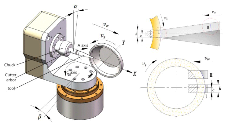
The diagram shown in Fig. 1 illustrates the schematic of grinding the oblique blade surface of an ultrasonic dagger blade. It represents the linear reciprocating grinding of the oblique blade surface at a specific grinding depth through the end face of a bowl-shaped cubic boron nitride (iCBN) grinding wheel. In the diagram, vw represents the linear feed rate of the dagger blade, vs represents the grinding linear velocity of the grinding wheel, and ds represents the equivalent diameter of the grinding wheel. α and β represent the pre-grinding orientations of the tool, where α is the rotation angle around the a axis and β is the rotation angle around the c axis.
The grinding force generated by a single abrasive grain is related to the depth of cut of the abrasive grain and the thickness of the abrasive chip (Li et al., 2017), which can be expressed as the grinding force per unit grinding area, and the expression for the unit grinding force is as follows:
where σ is the grinding force constant per unit area, is the average cross-sectional area of grinding chips, and ε is the coefficient affecting the unit grinding force related to friction.
The material of the workpiece is primarily removed by the abrasive grains at the outermost periphery of the grinding wheel's end face. In this paper, the equivalent mapping of the grinding arc at different feed positions of the grinding wheel is carried out, and it is mapped to the grinding arc of the grinding wheel when grinding square workpieces, as shown in Fig. 1. This includes the equivalent grinding arcs in Zone I and Zone II. Here, b represents the effective grinding width of the dagger blade, which is equal to the width of the square workpiece. c represents the offset of the square envelope frame containing the grinding arc of the dagger blade relative to the centerline. Therefore, the grinding force model of the dagger blade can be equivalently represented as the grinding force model of a workpiece with a constant width.
2.2 Grinding force from chip deformation
Assuming that the quadrilateral cone abrasive grain is ground using a tapered surface, the abrasive chips are produced by extrusion of the workpiece material, the grinding force on the front tool surface of the abrasive grain is the contact area of the abrasive grain and the abrasive chips multiplied by the grinding force per unit area (Younis et al., 1987), and the grinding force is established in this cutting attitude:
where S is the grit front surface and workpiece extrusion area and Fp is the grinding force per unit area.
Ndl is the dynamic abrasive grain linear density of grinding wheels and the dynamic effective abrasive line density per unit arc length:
where K1 and K2 are determined by the actual grinding condition, and .
Based on the average undeformed grinding thickness and grinding depth, find the contact area between the front surface of the abrasive grain and the abrasive chip (Younis and Alawi, 1984):
where Ndl is the dynamic abrasive grain linear density of grinding wheels, and ap is the grinding depth.
The average cross-sectional area of the abrasive chips can be obtained as
Normal and tangential chip deformation forces generated by a single abrasive grain are obtained:
The total chip deformation force in the grinding zone of the kinematic contact arc length is the sum of all the abrasive particles involved in grinding:
The total grinding chip deformation force in the grinding zone is obtained as
2.3 Friction from the slip friction
When grinding, the abrasive grain produces a circular surface or a small plane because of the abrasive tip, which slips and rubs against the workpiece surface, causing elastic deformation of the workpiece surface and generating frictional forces. The normal and tangential friction forces generated by the slip friction of a single abrasive grain (Tang et al., 2009) are
where δ is the contact area between the tip of the abrasive grain and the workpiece, is the average contact pressure between the abrasive grain and the workpiece surface, and μ is the friction coefficient.
The average contact pressure is based on the study of Malkin (1989), which gives
where p0 is the constant, Δ is the difference between the radius of the curvature and the grinding wheel radius, β is the coefficient determined by the mechanical properties of the friction surface, W is the normal loading, and A0 is the contact area.
According to the undeformed average grinding thickness and Eq. (9), the following are obtained.
The total slip friction is the sum of the friction generated by the abrasive grains involved in the slip friction and the end-face abrasive grains on the kinematic contact arc, but in order to reduce the friction generated on the end face during actual grinding, the grinding wheel end face is trimmed to an inner cone shape, so only the friction generated by the outermost abrasive grains on the end face is calculated in this paper.
The total slip friction force obtained is
where K3=4P0δ, K4=αδ, and K5=4P0βδ.
2.4 Friction generated by the abrasive debris flow
Relative motion occurs between the abrasive chip formation and the front tool surface of the abrasive grain, generating normal friction and tangential friction.
The total friction on the kinematic contact arc is the sum of all the abrasive particles involved in the cut.
The total frictional force generated by the outflow of grinding chips from the grinding zone is obtained:
where , and .
2.5 Grinding force model
In this paper, the single abrasive grinding force is divided into the chip formation force and friction force, where the friction force is divided into the friction force when the abrasive chips flow out and the friction force generated by the slip friction of the abrasive particles:
where Fc is the grinding chip formation force, Ff is the friction generated by the slip friction of abrasive grains, and Fcf is the friction generated by the abrasive debris flow.
The following are the total normal force and total tangential force during grinding.
, , K5=4P0δ, , K7=αδ, and K8=4P0βδ.
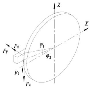
The unknown coefficients in Eqs. (20) and (21) are calculated based on the regression solution of the grinding force data measured by the grinding experiment, and Eqs. (20) and (21) calculate the total normal grinding force and the total tangential grinding force on the grinding wheel, while the grinding force on the workpiece in the x, y, and z directions is measured by the grinding experiment. In surface grinding force modeling, because the grinding depth is much smaller than the grinding wheel diameter, the tangential force is usually approximated as the force in the horizontal direction and the normal force is approximated as the force in the vertical direction. However, it is not directly transformed in face grinding, and it is known from the literature (Perveen et al., 2014) that the grinding forces can be regarded as a trapezoidal distribution on the grinding arc, and the horizontal and vertical grinding forces can be obtained according to Fig. 2 as follows.
Since the actual sharpening ∘ and the actual grinding width of the dagger blade decrease as the offset increases, i.e. the grinding contact arc length decreases, the grinding force also decreases, so the angle has little effect on the vertical component of the tangential force, and therefore the tangential force can also be approximated as the vertical grinding force.
3.1 Experimental protocol design
3.1.1 Experimental grinder
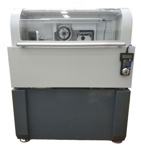
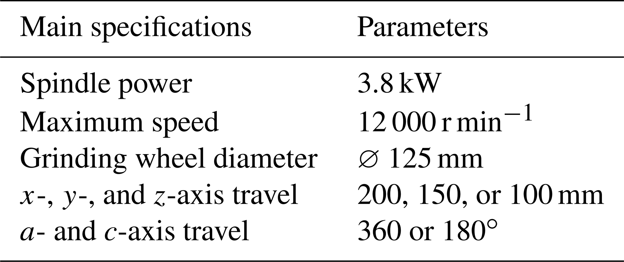
The grinding experiments are conducted on a self-developed non-standard ultrasonic tool dedicated five-axis four-linkage tool grinder (as shown in Fig. 3). The grinder's main spindle is an electric spindle, and it can grind various non-standard ultrasonic tools through a circulating oil-cooling system. The specific specifications and parameters of the machine tool are shown in Table 1.
3.1.2 Grinding wheel and workpiece
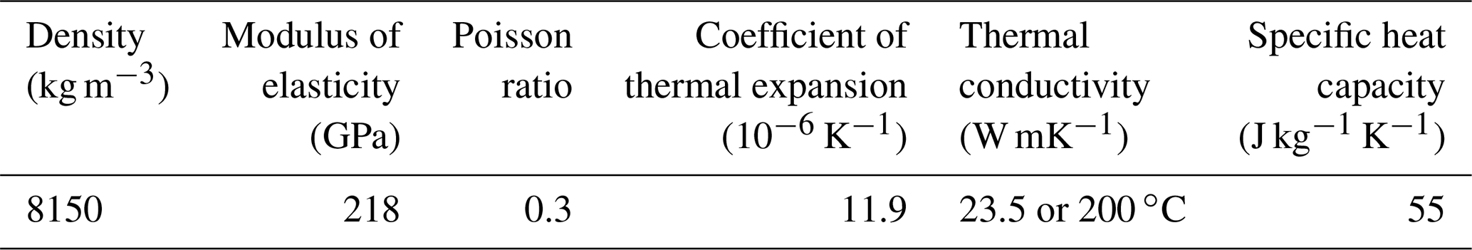
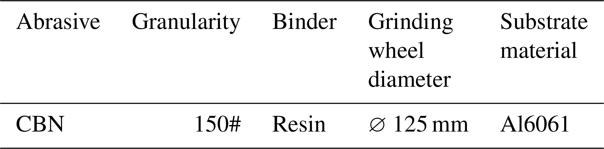
The workpiece material selected for this experiment is AISI M2, and the workpiece dimensions for the regression coefficient grinding force experiment are 5 × 30 × 100 mm. The material properties of the workpiece are shown in Table 2. The material characteristics of the workpiece determine the choice of grinding wheel abrasive. Since high-speed steel is a high-hardness material, ordinary abrasives cannot meet the processing requirements. In this experiment, cubic boron nitride abrasive wheels are used for grinding the workpiece. Considering processing efficiency and surface quality, a semi-fine grinding process is employed, and the grit size of the super-hard abrasive is generally chosen between 120 and 200 grit. In this study, a 150-mesh grinding wheel is selected, and the parameters are as shown in Table 3.
3.1.3 Experimental platform
The grinding experimental platform consists of a grinding process system and a grinding force measurement system as shown in Fig. 4. The grinding process system includes a grinding wheel, workpiece, force measurement table, and fixed base plate. The force measurement table is connected to the fixed base plate and the swivel seat of the grinding machine's c axis. During grinding, the bottom edge of the workpiece coincides with the centerline of the grinding wheel, which is zero offset. The measurement system consists of a force measurement table, a signal amplifier, and data acquisition software. During grinding, the main spindle rotates counterclockwise, and the grinding wheel first moves along the y axis to achieve the specified grinding depth. Then, the workpiece is fed along the x axis to remove material, while the force measurement table measures the grinding forces in the y and z directions.
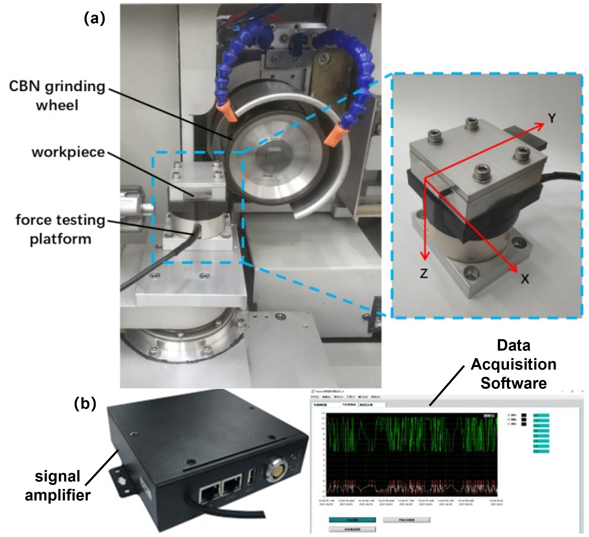
Figure 4Grinding test platform. (a) Grinding process system. (b) Grinding force measurement system (grinding force measurement system manufactured by ME-measurement systems GmbH).
Table 4The technical specifications of ME-K6D40 and HSGD6X-EC.
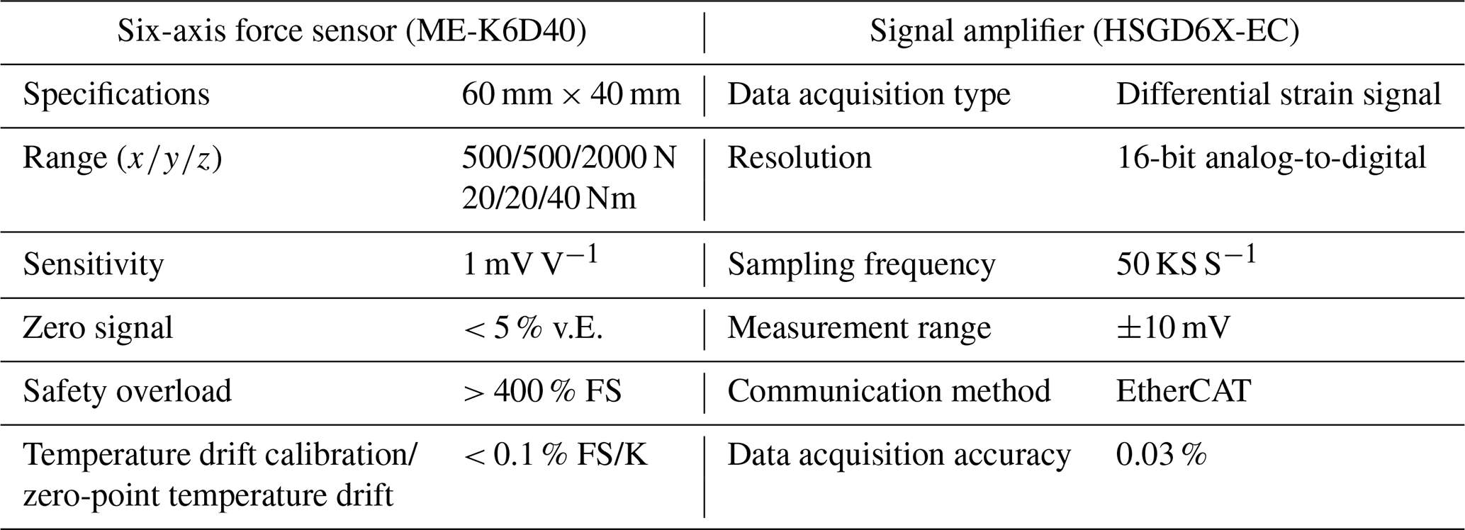
The force sensor model in the experiment is ME-K6D40 manufactured by ME-measurement systems GmbH in Germany, and it is paired with a signal amplifier, the HSGD6X-EC. The specific technical parameters are shown in Table 4. The data acquisition software employed is Huasoft. After obtaining the experimental data, the grinding force values are obtained through filtering and processing in MATLAB.
3.2 Grinding process parameter settings
Unlike conventional grinding, the material removal rate during ultrasonic scalpel blade grinding is high. According to the reference (Li et al., 2011), a gradual feed grinding process can be used to grind high-hardness materials, with a grinding depth of 0.1–30 mm, a feed rate of 5–500 mm min−1, and a grinding wheel speed of 20–60 m s−1. The grinding wheel manufacturer recommends a rough grinding depth of 0.05–0.1 mm and a grinding wheel speed of 28–33 m s−1. In summary, considering the practical process parameters for grinding ultrasonic scalpel blades, the rough grinding depth should be controlled at around 0.05 mm, the feed rate for the blade blank should be between 150 and 250 mm min−1, and the grinding wheel speed should be between 2500 and 3500 r min−1 (revolutions per minute). This yields good grinding results and ensures a long lifespan for the grinding wheel.
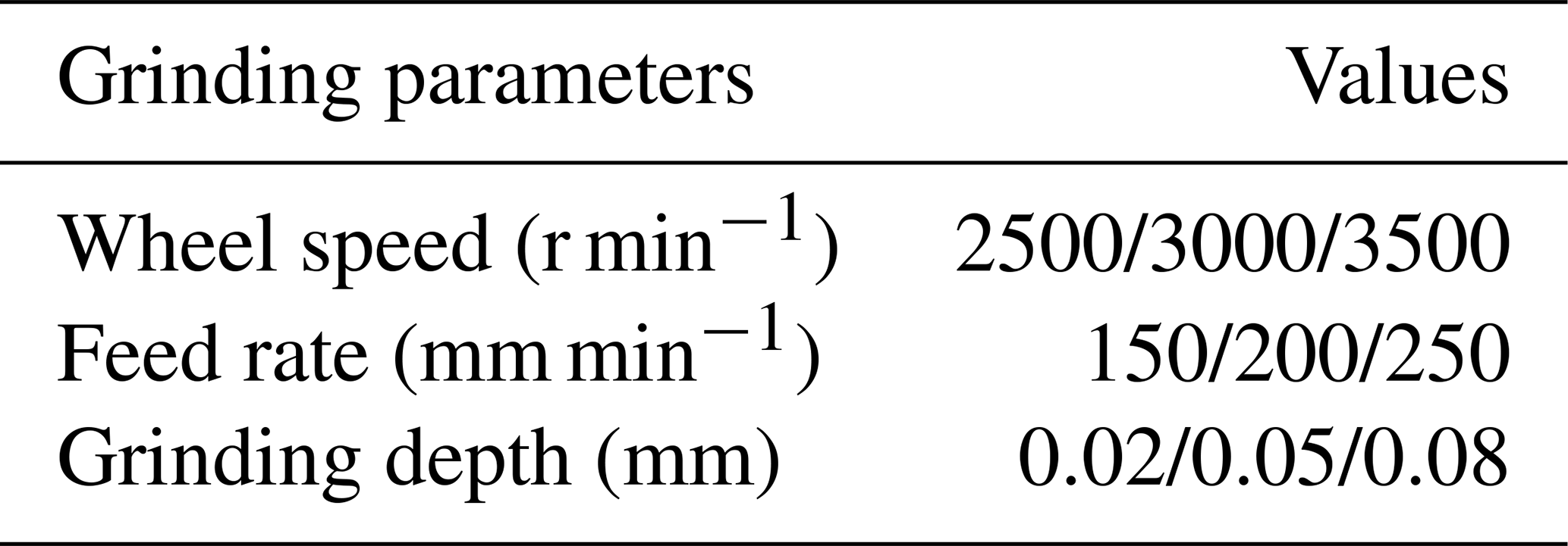
By analyzing the grinding force model in Sect. 2.5, it can be understood that grinding force is influenced by process parameters. In this experiment, variations in grinding force were studied by altering the grinding wheel speed, workpiece feed rate, and grinding wheel depth of cut. A full factorial experimental design was employed, with each parameter having three levels as shown in Table 5. Grinding forces were measured for all combinations of process parameters, and each set of parameters was tested three times to reduce random errors. During the experiment, efforts were made to maintain consistent grinding conditions. Severely worn grinding wheels were promptly dressed, and pre-grinding was performed on the dressed wheels. The grinding state was monitored by measuring the grinding forces using a force measurement table to ensure stability. The experiment proceeded only when the grinding wheel was in a stable grinding state.
3.3 Solution of the grinding force coefficient
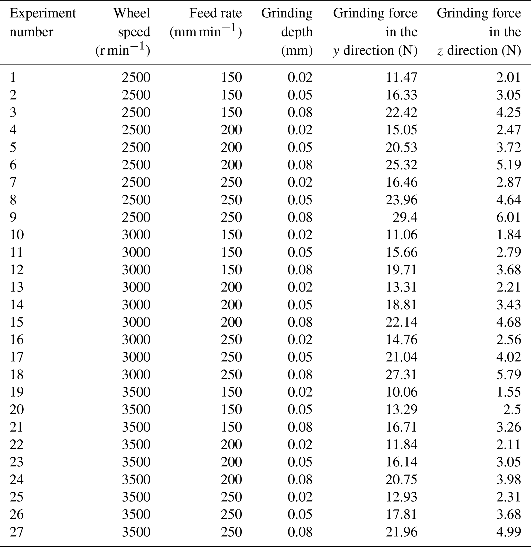
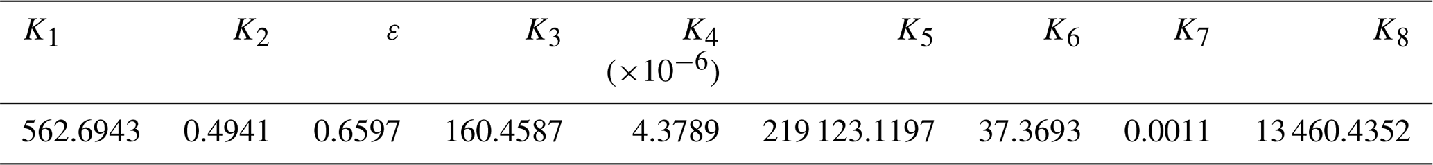
To validate the proposed theoretical grinding force model in this study, changes in grinding forces were investigated by varying the wheel speed, workpiece feed rate, and grinding depth. A full factorial experimental design was employed, with each parameter set at three levels. Grinding forces were measured for all combinations of process parameters, and each parameter combination was repeated three times to reduce random errors. The measured grinding force values are shown in Table 6. By regression analysis of the experimental data, the grinding force coefficients in Table 7 were obtained.
The final obtained grinding force models are
The prediction accuracy of the model was verified by comparing the predicted grinding force with the grinding force measured by the grinding experiment, and the single-factor grinding experiment was carried out to measure the grinding force by the control variable method.
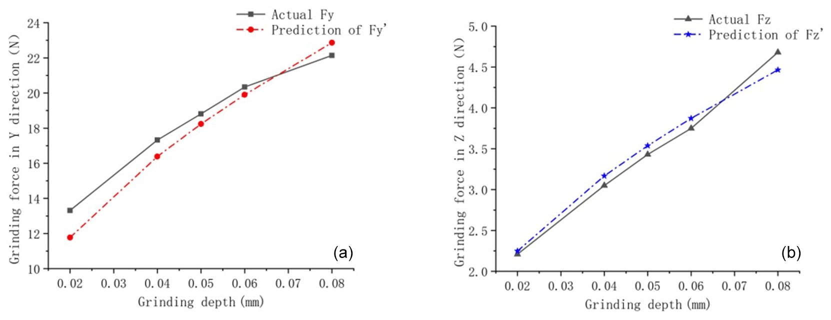
Figure 5ns=3000 r min−1, vw=200 mm min−1 verification of the grinding force: (a) grinding force in the y direction; (b) grinding force in the z direction.
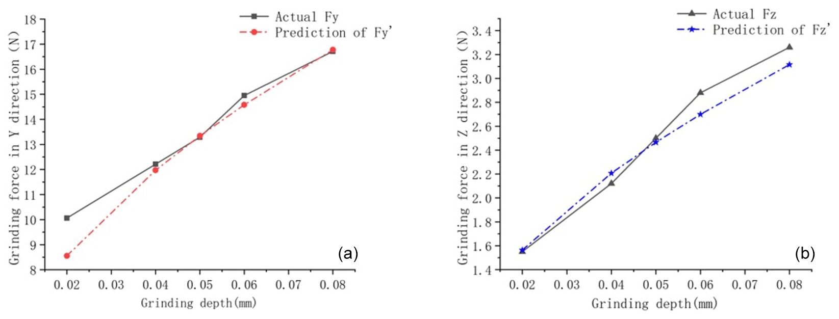
Figure 6ns=3500 r min−1, vw=150 mm min−1 verification of the grinding force: (a) grinding force in the y direction; (b) grinding force in the z direction.
The relationships between the test and theoretical values of the grinding force and the effect of each parameter are shown in Figs. 5 and 6. When ns=3000 r min−1 and vw=200 mm min−1, the maximum relative error between the predicted grinding force and the measured value in the y direction is 11.53 %, the minimum relative error is 2.14 %, and the average relative error is 5.08 %. The maximum relative error between the predicted grinding force and the measured value in the z direction is 3.25 %, the minimum relative error is 1.74 %, and the average relative error is 3.31 %. When ns=3500 r min−1 and vw=150 mm min−1, the maximum relative error between the predicted grinding force and the measured value in the y direction is 14.95 %, the minimum relative error is 0.38 %, and the average relative error is 4.03 %. The maximum relative error between the predicted grinding force and the measured value in the z direction is 6.26 %, the minimum relative error is 0.92 %, and the average relative error is 3.42 %.
The reasons for errors in measurement are as follows.
-
The grinding wheel exhibits runout errors due to manufacturing precision, causing vibrations during grinding. When the grinding depth is small, this can affect the actual grinding force measurement.
-
The actual shape of the abrasive grains on the grinding wheel is complex. In this study, the abrasive grains are simplified as single tetrahedral grains, and the cutting angles are determined. This simplification may not accurately represent the material removal process of all the abrasive grains.
-
The modeling of grinding forces did not take into account the thermal softening effect of the workpiece material caused by grinding heat.
-
Due to multiple repeated experiments, the wear of the grinding wheel can also affect the measurement of grinding forces before and after each set of experiments.
In summary, when the workpiece width is 5 mm, the average relative error between the predicted values from the grinding force model established in this paper and the measured values is within 10 %, indicating that, within the range of experimental process parameters, it is effective at predicting grinding forces.
3.4 Verification of the grinding force with variable edge width and analysis of results
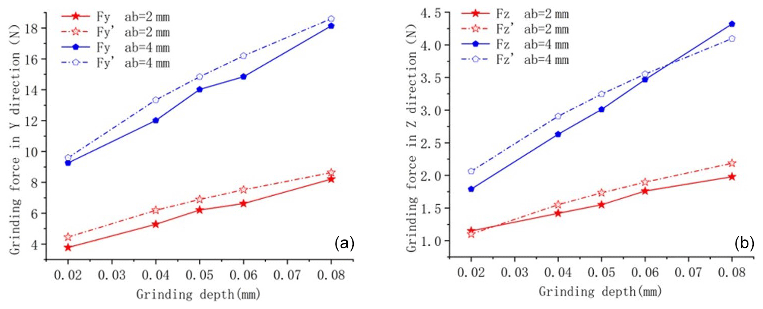
The grinding force model established was further verified by measuring the grinding forces of workpieces with different widths to effectively predict the grinding forces of dagger knives with different equivalent sharpening widths, and the experimental and predicted values of grinding forces are shown in Figs. 7 and 8. The cross-sectional dimensions of the ground workpiece are 5×30 mm, 4×30 mm, and 3×30 mm and the grinding wheel speed is 3500 r min−1.
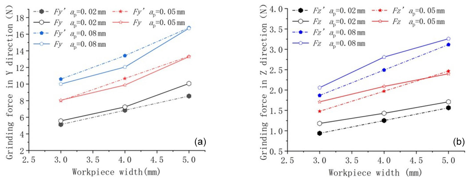
Figure 7ns=3500 r min−1, vw=150 mm min−1 verification of the grinding force for different workpiece widths.
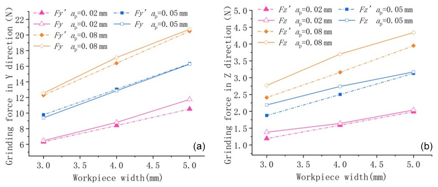
Figure 8ns=3500 r min−1, vw=200 mm min−1 verification of the grinding force for different workpiece widths.
In Figs. 7 and 8, at the same grinding depth, the experimentally measured grinding force increases with the grinding width in a nonlinear relationship, with an overall approximate exponential increase, and the theory predicts a linear relationship between the grinding force and the grinding width. The actual grinding force refers to the grinding force measured during experiments, while the predicted grinding force refers to the grinding force predicted by the grinding force model. When vw=150 mm min−1, the maximum relative error between the predicted grinding force and the measured value in the y direction was 14.96 %, the minimum relative error was 0.4 %, and the average relative error was 6.13 %. The maximum relative error between the predicted grinding force and the measured value in the z direction was 20.52 %, the minimum relative error was 2.74 %, and the average relative error was 9.84 %.
When vw=200 mm min−1, the maximum relative error between the predicted grinding force and the measured value in the y direction was 10.51 %, the minimum relative error was 0.33 %, and the average relative error was 3.46 %. The maximum relative error between the predicted grinding force and the measured value in the z direction was 14.63 %, the minimum relative error was 1.33 %, and the average relative error was 8.94 %.
3.5 Variable flute width grinding force model correction
Since the actual grinding force and the workpiece width are exponentially related and the equivalent grinding width varies along the feed position during dagger sharpening, which affects the maximum thickness of the grinding chips and the material removal mechanism and force ratio, in order to improve the prediction accuracy of the grinding force model, this paper introduces the exponential coefficient related to the grinding width, and based on the experimental data, the variable blade width grinding force model is modified to obtain
where k1=0.8347, k2=0.1070, k3=1.2397, and .
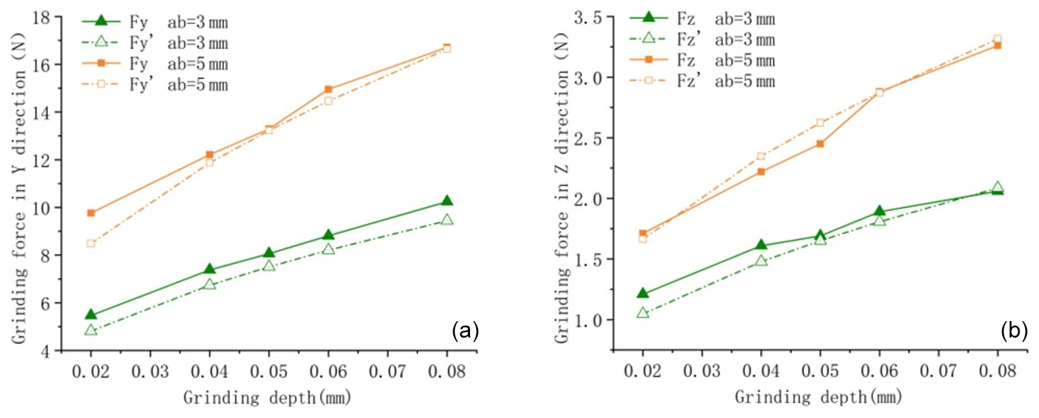
In order to verify the reasonableness of the introduced index, the actual grinding forces and predicted values for different process parameters and workpiece widths were verified by comparison as shown in Figs. 9 and 10.
In Fig. 9 the maximum relative error between the predicted grinding force in the y direction and the measured grinding force is 12.18 %, the minimum relative error is 0.44 %, and the average relative error is 6.13 %. The maximum relative error between the predicted grinding force in the z direction and the measured grinding force was 13.43 %, the minimum relative error was 0.27 %, and the average relative error was 4.70 %.
In Fig. 10 the maximum relative error between the predicted grinding force in the y direction and the measured grinding force is 12.98 %, the minimum relative error is 2.54 %, and the average relative error is 8.67 %. The maximum relative error between the predicted grinding force in the z direction and the measured grinding force was 11.76 %, the minimum relative error was 2.37 %, and the average relative error was 8.45 %.
Based on the aforementioned experiments, establishing the variable edge-width grinding force model through equivalent mapping and introducing the corrective coefficient for the grinding width are reasonable. This approach enhances the predictive accuracy of the model, resulting in an average relative error within 9 %. Thus, the established grinding force model is capable of predicting grinding force values for different equivalent edge widths, accurately forecasting the grinding force during dagger blade edge grinding. In comparison to traditional constant contact line blade surface grinding force prediction with an average error within 9 % (Yang et al., 2023), this further enhances the predictive accuracy.
In the context of grinding the tapered blade surface of dagger-shaped tools where the arc length of contact changes with feed, the current prevalent fixed contact arc length grinding force prediction methods fail to address the issue of changing arc length during grinding. Therefore, a grinding contact area equivalent mapping method has been proposed to rapidly and efficiently obtain a variable contact line model during the blade grinding process, enabling the acquisition of irregularly shaped material removal areas.
Since the contact arc length is approximately equal to the workpiece width and the actual grinding force exhibits an exponential relationship with the workpiece width, in order to further investigate the influence of the contact arc length on the grinding force prediction, exponential coefficients related to the grinding width are introduced. These coefficients are calculated through regression analysis and incorporated into the derivation of the variable edge-width grinding force model. The predicted values from this variable edge-width grinding force model have an average relative error within 9 %. This is beneficial for subsequent computational analysis of grinding forces and deformation during the actual grinding process of dagger blades, providing a theoretical foundation for subsequent grinding process compensation.
The grinding force model established in this paper is for static stability and does not consider the dynamic grinding processes, such as the influence of wheel deformation and vibration on grinding forces, which may deviate from real-world process systems. Further research is needed to investigate the grinding characteristics of the ultrasonic dagger blade, including enhancing the accuracy of the grinding force model for the dagger blade and considering the loading method and material removal mode. Subsequent research should also take into account the impact of material plastic deformation on grinding deformation.
Code and data are available on reasonable request.
Conceptualization: BY, TL, DC, JR, and WL; methodology: BY, TL, and DC; validation: BY; investigation: BY and TL; data curation: JR, WL, and YC; writing – original draft preparation: BY; writing – review and editing: BY and TL; visualization: JR; supervision: WL and YC. All the authors have read and agreed to the published version of the paper.
The contact author has declared that none of the authors has any competing interests.
The funding institution did not participate in and did not affect the research design.
Publisher’s note: Copernicus Publications remains neutral with regard to jurisdictional claims made in the text, published maps, institutional affiliations, or any other geographical representation in this paper. While Copernicus Publications makes every effort to include appropriate place names, the final responsibility lies with the authors.
This research was supported by the National Natural Science Foundation of China (grant no. 51975173) and the Zhejiang Public Welfare Technology Research Program/Industry Project (grant no. LGG21E050010).
This research has been supported by the National Natural Science Foundation of China (grant no. 51975173) and the Zhejiang Public Welfare Technology Research Program/Industry Project (grant no. LGG21E050010).
This paper was edited by Jeong Hoon Ko and reviewed by two anonymous referees.
Fu, Y., Tian, L., Xu, J., Yang, L., and Zhao, J.: Development and Application on the Grinding Process Modeling and Simulation, J. Mech. Eng., 7, 198–205, https://doi.org/10.3901/JME.2015.07.197, 2015.
Gao, T., Li, C., Zhang, Y., Yang, M., Cao, H., Wang, D., Liu, X., Zhou, Z., and Liu, B.: Mechanical Behavior of Material Removal and Predictive Force Model for CFRP Grinding Using Nano Reinforced Biological Lubricant, J. Mech. Eng., 13, 325–342, https://doi.org/10.1016/j.jmatprotec.2020.116976, 2023.
Gu, P., Zhu, C., and Tao, Z.: A grinding force prediction model for SiCp Al composite based on single-abrasive-grain grinding, Int. J. Adv. Manuf. Tech., 109, 1563–1581, https://doi.org/10.1007/s00170-020-05638-7,2020.
Jamshidi, H., Gurtan, M., and Budak, E.: Identification of active number of grits and its effects on mechanics and dynamics of abrasive processes, J. Mater. Process. Tech., 273, 116239, https://doi.org/10.1016/j.jmatprotec.2019.05.020, 2019.
Li, C., Li, X., Wu, Y., Zhang, F., and Huang, H.: Deformation mechanism and force modelling of the grinding of YAG single crystals, Int. J. Mach. Tool. Manu., 143, 23–37, https://doi.org/10.1016/j.ijmachtools.2019.05.003, 2019.
Li, C. H., Qi, L. Y., and Zhao, H. Y.: Application and Development of High-Efficiency Abrasive Finishing, Adv. Mat. Res., 189, 3113–3116, https://doi.org/10.4028/www.scientific.net/AMR.189-193.3113, 2011.
Li, H. N., Yu, T. B., Wang, Z. X., Zhu, L. D., and Wang, W. S.: Detailed modeling of cutting forces in grinding process considering variable stages of grain-workpiece micro interactions, Int. J. Mech. Sci., 126, 319–339, https://doi.org/10.1016/j.ijmecsci.2016.11.016, 2017.
Li, L., Ren, X., Feng, H., Chen, H., and Chen, X.: A novel material removal rate model based on single grain force for robotic belt grinding, J. Manuf. Process., 68, 1–12, https://doi.org/10.1016/j.jmapro.2021.05.029, 2021.
Malkin, S.: Grinding technology: theory and applications of machining with abrasives, SME, 115–141, ISBN 9780831132477, 1989.
Ni, J., Feng, K., Al-Furjan, M. S. H., Xu, X., and Xu, J.: Establishment and Verification of the Cutting Grinding Force Model for the Disc Wheel Based on Piezoelectric Sensors, Sensors, 19, 725, https://doi.org/10.3390/s19030725, 2019.
Perveen, A., Rahman, M., and Wong, Y. S.: Modeling and simulation of cutting forces generated during vertical micro-grinding, Int. J. Adv. Manuf. Tech., 71, 1539–1548, https://doi.org/10.1007/s00170-013-5572-y, 2014.
Sun, J., Kang, R., Zhou, P., Dong, Z., and Wang, Y.: Review on Ultrasonic Cutting of Honeycomb Core, J. Mech. Eng., 9, 298–319, 2023.
Sun, L., Yang, S., Yang, L., Zhao, P., Wu, P., and Jiang, Z.: A New Model of Grinding Forces Prediction for Machining Brittle and Hard Materials, Proc. CIRP, 27, 192–197, https://doi.org/10.1016/j.procir.2015.04.065, 2015.
Tang, J., Jin, D., and Chen, Y.: Modeling and experimental study of grinding forces in surface grinding, J. Mater. Process. Tech., 209, 2847–2854, https://doi.org/10.1016/j.jmatprotec.2008.06.036, 2009.
Wang, Y., Wang, X., Kang, R., Kang, R., Sun, J., and Dong, Z.: Analysis of Influence on Ultrasonic-assisted Cutting Force of Nomex Honeycomb Core Material with Straight Knife, J. Mech. Eng., 19, 73–82, https://doi.org/10.3901/JME.2017.19.073, 2017.
Wang, Y., Li, X., Wu, Y., Mu, D., and Huang, H.: The removal mechanism and force modelling of gallium oxide single crystal in single grit grinding and nanoscratching, Int. J. Mech. Sci., 204, 106562, https://doi.org/10.1016/j.ijmecsci.2021.106562, 2021.
Yang, H., Jiang, B., Tang, C., and Liu, W.: Simulation and experimental study of SiCp Al composite based on single abrasive grinding, Aeronautical Manufacturing Technology, 66, 103–109, 2023.
Yang, M., Li, C., Zhang, Y., Jia, D., Li, R., Hou, Y., and Cao, H.: Effect offriction coefficient on chip thickness models in ductile-regime grinding of zirconia ceramics, Int. J. Adv. Manuf. Tech., 102, 2617–2632, https://doi.org/10.1007/s00170-019-03367-0, 2019.
Younis, M., Sadek, M. M., and El Wardani, T.: A new approach to development of a grinding force model, ASME, 109, 306–313, 1987.
Younis, M. A. and Alawi, H.: Probabilistic Analysis of the Surface Grinding Process, T. Can. Soc. Mech. Eng., 8, 208–213, 1984.
Zhang, Y., Li, C., Yang, M., Jia, D., and Li, J.: Analysis of single-grain interference mechanics based on material removal and plastic stacking mechanisms in nanofluid minimum quantity lubrication grinding, Proc. CIRP, 71, 116–121, https://doi.org/10.1016/j.procir.2018.05.082, 2018.