the Creative Commons Attribution 4.0 License.
the Creative Commons Attribution 4.0 License.
 | 21 Nov 2023
Assistance control strategy for upper-limb rehabilitation robot based on motion trend
Haojun Zhang
Tao Song
Leigang Zhang
Robot-assisted rehabilitation has proven to improve a subject's upper-extremity motor function. However, it is still challenging to control the robot to provide minimal assistance based on the subject's performance. This paper proposes a motion-trend-based assistance control strategy to solve this problem. The control strategy provides the corresponding normal and tangential forces by constructing an adaptive virtual assistance force field around a predetermined training trajectory. In the normal direction, a performance function based on the position-tracking error and normal motion trend is established to adjust the normal assistance force field strength in real time; in the tangential direction, a performance function based on the tangential interaction force and tangential motion trend is established to adjust the tangential assistance force field strength in real time. Additionally, good motion trends can quickly reduce the assistance force field. The normal motion trend represents the state of the subject moving toward the target trajectory, and the tangential motion trend represents the state of increasing tangential interaction force. Finally, the performance of this control strategy was evaluated by training experiments with eight healthy subjects. Preliminary experiments showed that the normal assist force in the active movement phase was 92.48 % smaller than that in the poor phase, and the tangential assist force was 90.73 % smaller than that in the slack phase. And the normal assist force and tangential assist force will become zero within 0.2 s when the subject has a good tendency to move. This shows that the control strategy proposed in this paper can quickly adjust the assistance according to the subject's motor performance. In addition, the assistance can be quickly reduced when the subject has a good movement trend. Future work will incorporate OpenSim (muscle and bone simulation software) to develop a pathway suitable for the subject's arm rehabilitation.
- Article
(9810 KB) - Full-text XML
- BibTeX
- EndNote


Epidemiology indicates that stroke is one of the leading causes of disability in patients (Hatem et al., 2016), and it significantly reduces functional capacity and activities of daily living (ADLs) (Pilutti et al., 2011; Battiston et al., 2017). Clinical studies have demonstrated that upper-limb rehabilitation robots can be effectively used relative to rehabilitation therapists to improve upper-limb motor function and even ADL abilities (Kwakkel et al., 2008; Milot et al., 2013).
In past research, various types of upper-limb rehabilitation robots have been designed to better assist patients in rehabilitation training, and they are mainly divided into end-effector type and exoskeleton type (Gassert and Dietz, 2018). The end-effector upper-limb rehabilitation robots mainly include MIT-MANUS (Krebs et al., 2004), GENTLE/S (Loureiro et al., 2003), EULRR (Zhang et al., 2021), etc. The exoskeleton upper-limb rehabilitation robots mainly include ARMIN (Nef et al., 2009), Rupert (Sugar et al., 2007), ALEX (Ruffaldi et al., 2014), etc. Although exoskeleton-based upper-limb rehabilitation robots can train subjects in specific joints, end-effector upper-limb rehabilitation robots have a superior advantage in ADL training (Chang and Kim, 2013).
In addition to the type of mechanics and actuators, the control strategy of a rehabilitation robot has a significant impact on the efficiency of treatment, and some studies have reviewed the control strategies of most rehabilitation robots (Proietti et al., 2016; Babaiasl et al., 2016; Tucker et al., 2015). According to the Brunnstrom theory, the control strategy of the robot requires a rigid controller to drive the patient's arm for movement due to the difficulty of moving the limb in patients in the early recovery stage (Sawner et al., 1992). As for the later rehabilitation process, as the patient regains partial motor ability, it is necessary for the patient to actively participate in the exercise as much as possible at this time, which helps to induce neuroplasticity and improve the rehabilitation effect (Houwink et al., 2013; Muratori et al., 2013). Therefore, for patients who have regained partial upper-extremity mobility, this is the time to provide the least restrictive assistance, also known as assist-as-needed (AAN) control, based on the patient's motor performance (Pehlivan et al., 2016).
In some past studies, some rehabilitation robots have implemented AAN strategies in rehabilitation therapy (Cao et al., 2021; Mounis et al., 2019). An important challenge of the current AAN control strategy is to estimate the subject's motor ability to provide minimal assistance and to be able to adapt to different performances of rehabilitation (Frullo et al., 2017). Several control strategies have been proposed to solve this problem. Mounis et al. (2019, 2020) determined a subject's motor performance by assessing their trajectory deviation, velocity, and time indexes in a trajectory-following motion to self-adjust the control gain. Guo et al. (2022) proposed to determine the subject's motor ability through the trajectory deviation and the assistance force. However, the above approach is too one-sided in identifying the subject's motor ability.
To better assess the subject's motor ability, Li et al. (2022) assessed a subject's abilities by electromyography (EMG) and trajectory-tracking errors to determine the gain of the assistance force field. Although EMG-based methods may be suitable for low-degree-of-freedom robots, there are some difficulties in interpreting these signals. Leconte and Ronsse (2016) achieved AAN control by using the subject's output power and trajectory deviation as evaluation functions. Luo et al. (2017) combined the estimated subject impedance parameters and used the minimum principle to determine the impedance parameters of their controller. Papaleo et al. (2013) used the subject's motion accuracy and inter-joint coordination as evaluation functions to adjust controller stiffness and duration to achieve AAN control. In addition, Luo et al. (2019) proposed the use of radial basis function (RBF) neural networks to obtain the maximum output force of the subject and then to adjust the control gain in combination with the trajectory-tracking error. Estimation by RBF neural networks can filter out the effects of perturbations due to factors such as subject laziness. Taheri et al. (2016) proposed the evaluation of motor ability through deviations between an unimpaired model of motor control forces and a kinetic model of the subject, where the kinetic model learns the inertial forces required to allow accurate motion. In addition to the above studies, some of the studies assessed a subject's impedance parameters and others altered reference trajectories for assistance (Wang et al., 2019; Peng et al., 2018).
Although some of the above control strategies can better assess the subject's motor ability, most of them follow a timed trajectory, which has a relatively large limitation for the subject's active freedom. Some of the studies achieved this by adding an assistance force field around the trajectory to obtain freedom in the timing of movement. Lin et al. (2020) proposed a path control technique that constructs a free-motion region around the desired path and designs a moving window to propel the user's limb along the target path. However, the temporal freedom is still limited because the moving window moves at a predefined velocity along the path. Some papers provided assistance by adding gradient-varying assistance force fields around the trajectory so that it moves freely with less or no assistance force within the assistance force field; outside the assistance field, its assistance force increases in gradient with increasing deviation (Zhang et al., 2020; Pan et al., 2022; Zhang et al., 2023). Sufficient time freedom is provided by using this approach. In addition, Asl et al. (2020) constructed an ideal velocity field around the path and defined a path-tracking task in the velocity field, after which the AAN performance was obtained by adjusting the target impedance in real time through the subject's motion trajectory deviation. Although the abovementioned control systems can be adapted to different rehabilitation phases by changing the control parameters, they cannot provide adaptive assistance by accurately assessing the subject's motor ability as their assistance force fields are predefined. Vergaro et al. (2010) proposed an adaptive variable force field scheme in which the controller adaptively varies the strength of the normal-assisted force field by assessing the subject's motor ability based on the average value of the motor deviation. However, this approach ignores the more complex motor abilities of the subjects.
In this paper, we develop an adaptive force field-assisted control strategy based on motion trend, which can adjust the assistance in real time according to the subject's motion performance and quickly remove the assistance when the subject has a positive motion trend. We construct an assistance force field around the rehabilitation training path, consisting of a normal and tangential assistance force field. For the normal assistance force field, the subject can move freely within the first layer of the force field, and outside the first layer of the force field they will be subjected to an assistance force that increases in a gradient along the increasing deviation. The strength of the normal assistance force field is determined in real time by trajectory deviation and normal motion trend. For the tangential assistance force field, the strength of the tangential assistance force field is determined in real time based on the tangential interaction force and the tangential motion trend. In addition, a coefficient determined by the motion trend is introduced in the normal and tangential directions, which can reduce the strength of the assistance force field immediately when the subject's motion trend is good. Moreover, the above performance indexes are calculated by the method of weighted mean filtering, which can effectively filter out the influence caused by interference. The trend of normal motion is determined by the normal interaction force, and the trend of tangential motion is determined by the rate of change of the tangential interaction force. Finally, the effectiveness of the control strategy was verified experimentally with three healthy male subjects under different conditions. The experimental results illustrate that the control strategy can be quickly adapted to different motion performances and, in addition, quickly reduce the assistance when the movement trend is positive.
Compared to existing work, the main contributions of this paper are summarized as follows:
-
This paper proposes a way to obtain performance indexes in real time based on moving-weighted-mean filtering and processing of data from the previous period, which can eliminate the influence of reduced performance indexes due to a subject's interference or laziness rather than weak motor ability, and it can better reflect the current period of a patient's motor ability compared to the general way of calculating the mean.
-
Given the current inadequacy of the existing performance parameters based on position error and other performance parameters to represent the patient's motor ability, this paper additionally introduces the subject's interaction force into its motor ability evaluation and processes it as a motion trend indicator, which can quickly and comprehensively analyze the subject's motor ability. In addition, by adding a motion trend coefficient, the intensity of the assistance force field can be reduced immediately when the subject moves in the direction of a good motion trend, promoting active participation of the subject in the motion.
The rest of this paper is organized as follows: the structure and admittance control of the rehabilitation robot are described in Sect. 2; the implementation of the motion-trend-based control strategy is presented in Sect. 3; the experimental analysis of the designed control strategy using eight healthy subjects is presented in Sect. 4 to illustrate the effectiveness of the control strategy; and the discussion and conclusion are presented in Sects. 5 and 6, respectively.
2.1 Description of upper-limb rehabilitation robot
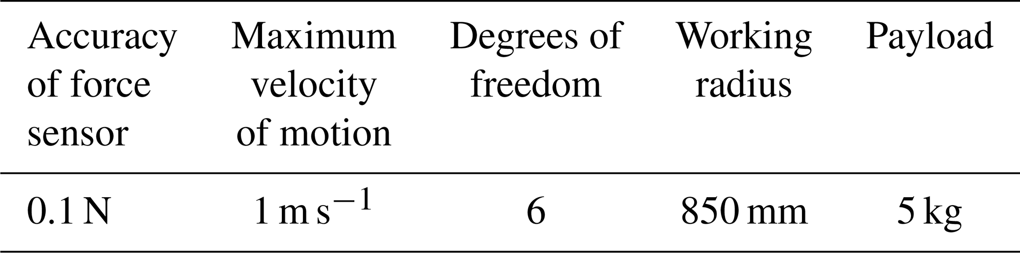
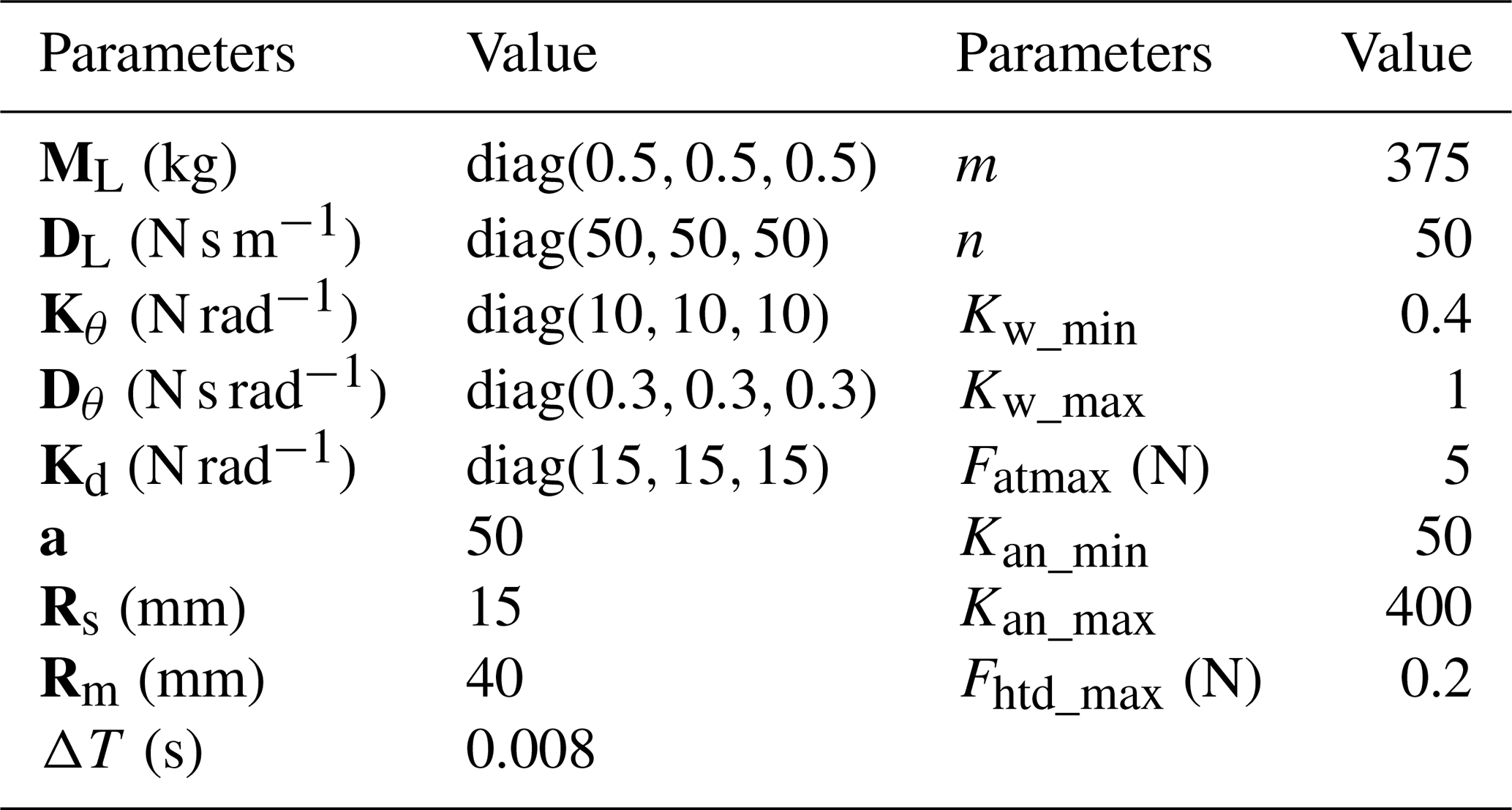
This paper's upper-limb rehabilitation robot is of the end-effector type and is based on the UR5 robotic arm design (Jiang et al., 2022; Xu et al., 2022). It has 6 degrees of freedom and carries a six-dimensional force sensor at the end. Compared to the general design of upper-limb rehabilitation robots, it can perform not only planar task training but also task training in space. To more clearly describe the upper-limb rehabilitation robot in this paper, Fig. 1 shows a 3D model drawing. In addition, the performance parameters related to the upper-limb rehabilitation robot are given in Table 1.
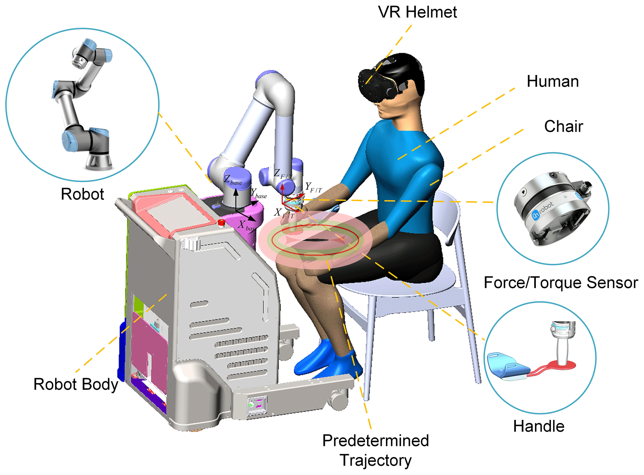
Figure 1The three-dimensional model of the end-effector-type upper-limb rehabilitation robot.
Table 1Upper-limb rehabilitation robot performance parameters.
2.2 Implementation of admittance control
To ensure a certain degree of suppleness during the interaction between the robot and the subject, admittance control is used here to produce a mass-damping-spring interaction effect during the interaction between its subject and the robot. For ease of expression, the control law for admittance control in Cartesian space in a single-degree-of-freedom system can be expressed as
where is the combination of the interaction force and the interaction torque, which can be measured by the end sensor. is the combination of assistance force and assistance torque, is the actual controlled positional pose, and is the desired positional pose. M is the mass matrix, D is the damping matrix, K is the stiffness matrix, and xyz and rxryrz are the position and Euler angle of the robot end-effector, respectively.
In this paper, we mainly consider the interaction control strategy between the subject and the robot in the Cartesian position, while for the interaction control on the orientation we just consider the pose angle restriction. Therefore, it is necessary to decompose the admittance controller in Eq. (1) into the admittance controller of the Cartesian space position and the Cartesian space orientation. For the interactive control of Cartesian spatial position, we have to ensure the active nature of the subject's motion, then the desired spatial linear velocity and the desired spatial linear acceleration are both zero, and the effect of the position directional stiffness term is removed. For the interactive control of Cartesian spatial orientation, the robot end pose cannot be uncontrollable or in a fixed position due to the consideration of the interaction between the robot end and the subject. Therefore, a Cartesian pose guide controller based on one target Euler angle is used to manage the orientation at the terminal end of the robot. The overall admittance controller is as follows:
Here, and represent the normal assistance force and tangential assistance force, respectively, which will be described in detail later. and represent the interaction force and the interaction torque, respectively; is the combined force of the assistance force and the interaction force. and are the mass and damping matrix of the Cartesian position admittance controller, respectively; is the actual controlled end line velocity; and are the stiffness and damping matrix of the Cartesian orientation admittance controller, respectively. is the robot end Euler angle, and is the controlled end angular velocity.
Since the upper-limb rehabilitation system uses the UR5 robotic arm as a carrier to complete the assistance function, the robot motion is controlled by driving the joint velocity in this paper, and the joint angular velocity whose input is required is calculated as follows.
is the Jacobi matrix of the robot, and is the joint angular velocity input to the robot.
3.1 Assistance force field design
In this subsection, to facilitate the subjects to actively participate in the rehabilitation training and follow the trajectory as much as possible, an assistance force field that can provide normal assistance force and tangential assistance force is designed in this section, as shown in Fig. 2. For the normal assistance force field perpendicular to the trajectory direction, the normal assistance force field is designed as a force field with a variable three-layer virtual region to allow the subject to stay within the tolerance range and have a certain degree of freedom as much as possible. The first virtual region is designed as a free motion region; in the second virtual region, the subject will be subjected to a smaller assistance force that increases with the trajectory deviation; in the third virtual region, the assistance force is designed to increase rapidly with the trajectory deviation in this region. In addition, to prevent subjects from being lazy during training, a variable assistance force field is added in the tangential direction, which can be adapted to the subject's exercise performance to change the intensity of the assistance force field and promote the subject's participation in rehabilitation training. The following is the specific design of the assistance force field.
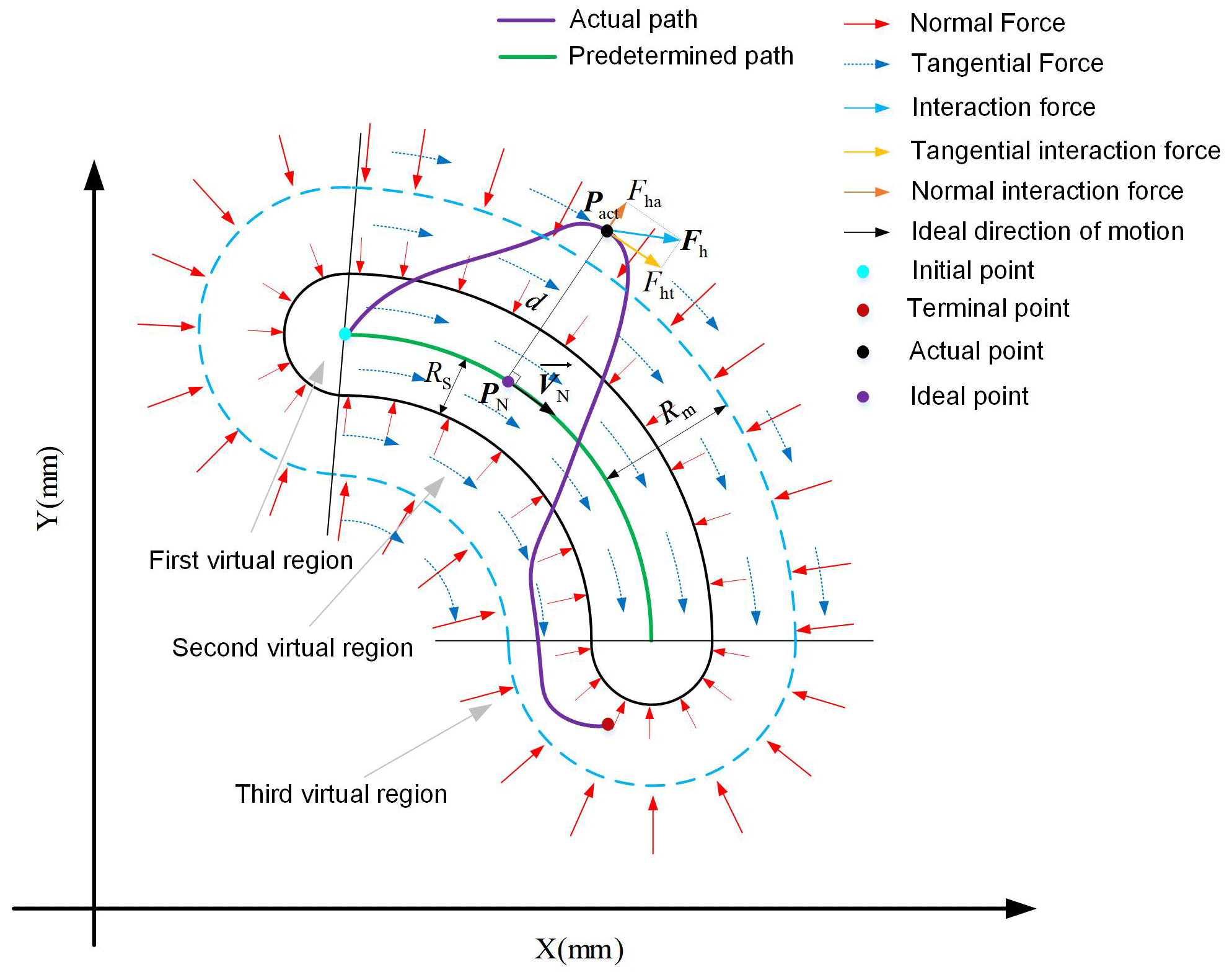
Since the relative relationship between the ideal trajectory position PN(xNyNzN) and the actual position Pact(xactyactzact) determines the value and direction of the robot assistance force and since the position of the robot end varies with time, a search algorithm would be needed to define the ideal reference position in real time during the training process. The actual position defined here corresponds to the ideal position of the subject as the minimum Euclidean distance from the current point of moving to the target trajectory, which can generally be approximated by iterative lookup (Zhang et al., 2021).
The Euclidean distance d between the actual position Pact and the ideal position PN can be obtained as
Variable d also represents the deviation between the current motion position and the target trajectory. Combined with the above description, the proposed force field control strategy is as follows:
Here, and denote the stiffness term and damping term of the normal assistance force, respectively, where the damping term FD is to ensure that the normal assistance force is damped with the damping term coefficient to make its system stable. The section from 0 to Rs is the first virtual region, which is not subject to normal assistance force, the section from Rs to Rm is the second virtual force field region with a stiffness coefficient of , and the section above Rm is the third virtual force field region, where the stiffness coefficient increases at the rate of a⋅Kan deviation increases. represents the direction of the normal force, which can be calculated by Eq. (15). is the maximum tangential assistance force, and is the tangential assistance coefficient. is the direction of the tangential assistance force, which is the same as the velocity direction VN of the ideal locus position point PN corresponding to the current position; a is the coefficient of variation.
For ease of control, it is simplified here that the normal stiffness coefficients Kan and tangential assistance coefficients Kat have only diagonal terms, and their diagonal terms all have the same elements. They satisfy the following relationship:
Here Kani and Kati are named as normal force field strength coefficient and tangential force field strength coefficient, respectively. In the following, the strength of the assistance force field is adjusted by changing Kani and Kati, mainly by assessing the subject's exercise performance. Therefore, once the training trajectory is determined, adaptive assistance force fields can be generated around the trajectory, whose force field distribution in the case of and is shown in Fig. 3.
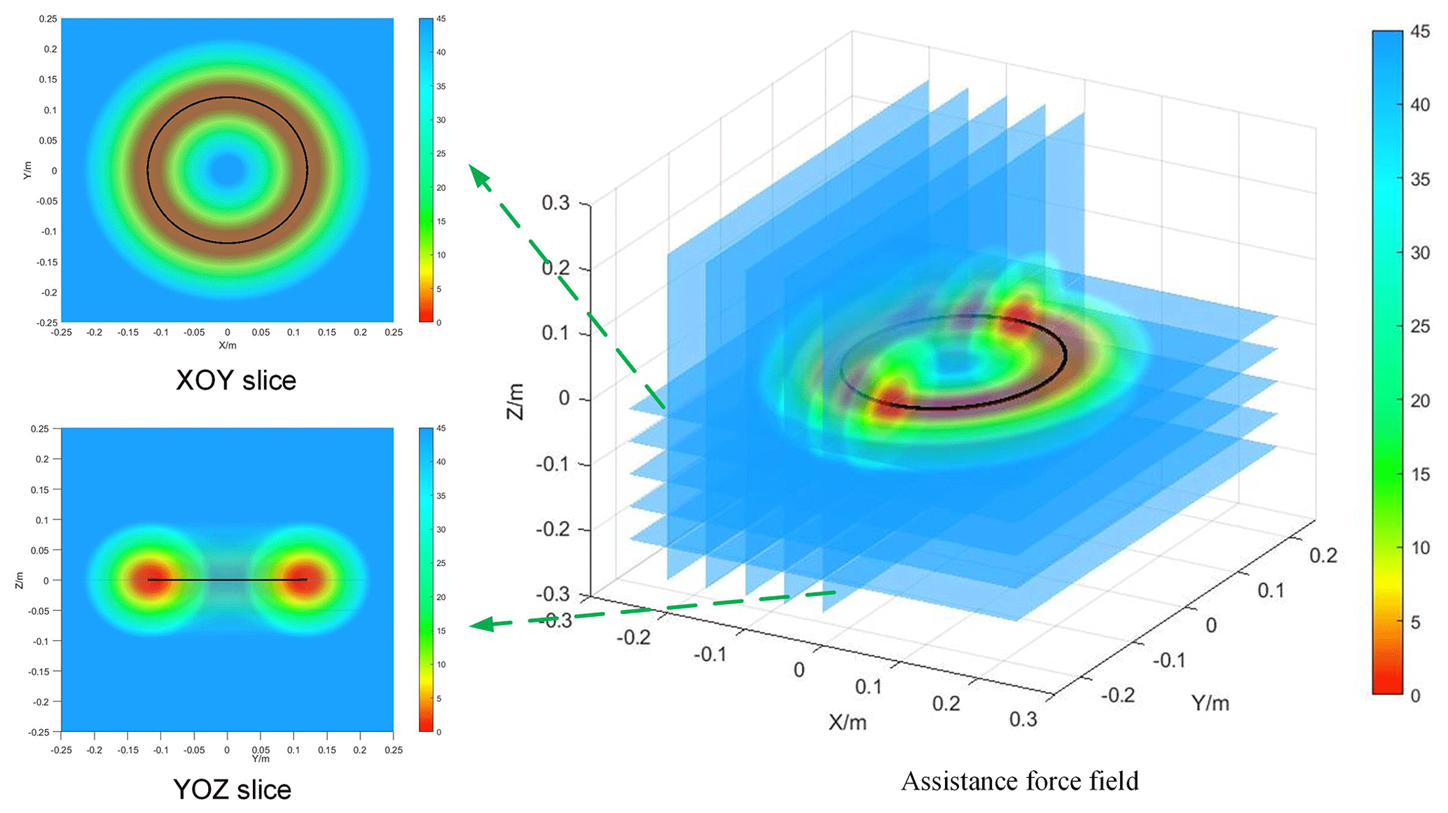
Figure 3Assistance force field distribution diagram using circular trajectory as the target trajectory.
3.2 Motor ability assessment based on motion trend
In the above, the implementation of the assistance force field has been defined. The following section focuses on changing the strength of the assistance force field in real time by assessing the subject's normal and tangential motor ability.
3.2.1 Assessment of normal motor ability
For the rehabilitation process, subject position deviation has a significant role in the subject's arm position sense exercise. In this paper, it is determined that the error index is calculated only after the subject exceeds the free motion zone, so the error index for the current period t is defined as follows:
Here, dt is the positional deviation at moment t.
We ensure that a subject's motor performance indicators can be updated in real time based on motor performance in the previous time window and also to weaken the effect of motor performance further away from the current moment on the motor performance indicators. In this paper, we use weighted moving-mean filtering to achieve this, which means introducing weight coefficients Kw based on moving-mean filtering. For performance indexes in the previous time window, the following are true: first, the closer the index is to the current time, the larger the weight factor is; second, the further away the index is from the current time, the smaller the weight factor is. So the weighting factor Kw is calculated as follows:
where Kw_min and Kw_max represent the minimum weighting coefficient and maximum weighting coefficient, respectively. i represents the number of frames in the current time window, and Tall is the number of frames in the time window.
In summary, its weighted average error index Ew is calculated as follows:
Here, Tall=m, the move time window is m⋅ΔT, m is the number of frames in the time window, and ΔT is the controller control period.
However, it is not enough to consider only the subject's motion deviation, we also need to consider the subject's normal motion trend. This is because we expect the control system to provide smaller assistance when the direction of the interactive force tends to the target trajectory, even if the trajectory deviation is relatively large; in contrast, we expect the control system to provide larger assistance when the direction of the interactive force is far from the target trajectory. The design normal motion trend index is as follows.
Here, we decompose the interaction force into the tangential direction parallel to the trajectory and the normal direction perpendicular to the trajectory, as shown in Fig. 2. The interaction forces in these two directions are calculated as follows:
where and are the normal interaction force and tangential interaction force of the subject, respectively.
Based on the above theory, the index Inmt for the trend of normal motion is determined as follows:
where Fha_max is the upper limit of normal interaction force calculation, and is the normal interaction force at time t. Here, the moving-weighted-mean filter is still used, and the moving time window is m⋅ΔT. From Eq. (23), it can be obtained that when the subject tends to the target trajectory, the result is less than one, decreasing the normal force field strength; when the subject is far from the target trajectory, the result is greater than one, increasing the normal force field strength.
The normal integrated performance index Incm is
Then, the normal assistance force field stiffness coefficient Kani is determined as follows:
where Kani_max and Kani_min are the upper and lower limits, respectively, of the normal force field strength coefficient. Fan1 is obtained by substituting the obtained Kani into Eq. (12). In addition, a normal motion trend coefficient β is added here. This is because when subjects tend to move toward the trajectory, changing the strength of the normal assistance force field by Incm alone is slow and does not promote the active participation of subjects in the movement well. This problem is solved here by adding a normal motion trend coefficient β. The definition of coefficient β is as follows:
Similarly, the values of coefficient β are implemented using a moving-weighted-mean filter. The time window is n⋅ΔT. Equation (27) shows that the coefficient β decreases rapidly as the subject tends to move toward the trajectory, resulting in a rapid decrease in the strength of the normal assistance force field. When the subject is moving away from the trajectory, β is 1, and the normal assistance force field strength only changes slowly according to the normal composite performance index Incm. This indicates that adding the normal motion trend coefficient β only restricts the subject's motion toward the outside of the trajectory and does not promote the subject's motion toward the inside of the trajectory.
3.2.2 Assessment of tangential motor ability
To assess the subject's tangential motility assessment, we first introduced tangential interaction forces. When the tangential interaction force is greater, this represents a better tangential motion of the subject and the robot can provide as little or no assistance force as possible. When the subject is too weak to move, the robot needs to provide tangential assistance force to drive the subject to move.
In addition, we also need to consider the subject's tangential motion trend and analyze whether the subject now tends to actively increase the tangential interaction force or actively decrease it. With the same tangential interaction force, the control system should provide a smaller assistance force for positive trends and a larger assistance force for negative trends. As with the calculation of normal performance indexes above, the same moving-weighted-mean filter is used here for the calculation of tangential performance indexes. Therefore, the tangential performance index Itcm is obtained by combining the subject's tangential interaction force and its rate of change Fhtd.
where the time window is m⋅ΔT. Fhtd_max represents the upper limit of the force transformation rate. The right-hand term in Eq. (27) is the tangential motion trend. Therefore, the tangential force field strength coefficient Kati can be determined as follows:
Similarly, to allow for a rapid decrease in the assistance force when the subject has a positive motion trend, the tangential motion trend coefficient g is introduced here and defined as follows:
Equation (30) demonstrates that the adaptive coefficient g decreases when the subject increases the tangential interaction force, leading to a rapid decrease in the assistance force; when the subject decreases the tangential interaction force, its coefficient g is 1 and the tangential assistance force increases gradually according to Itcm.
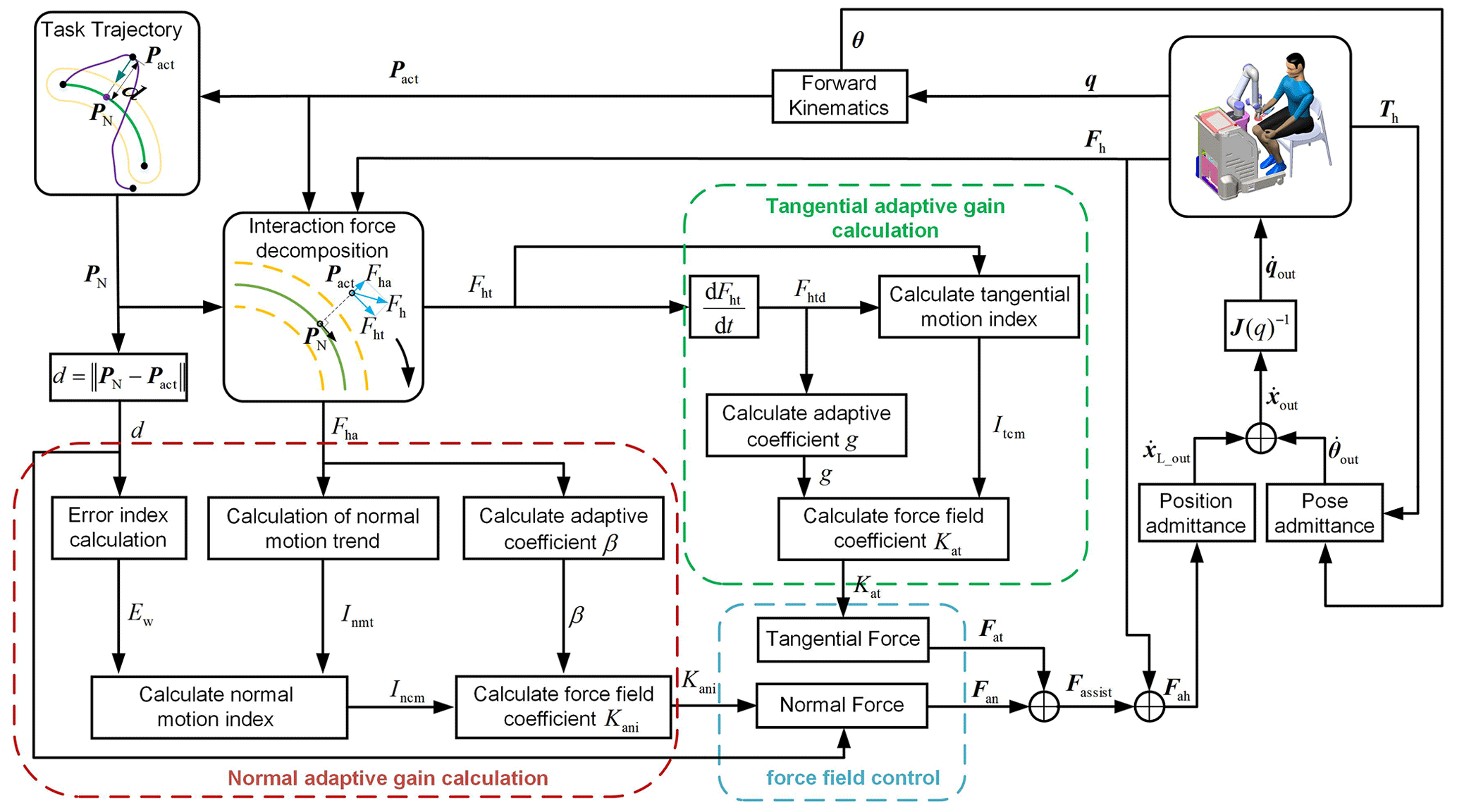
In summary, Fig. 4 shows a diagram of the proposed motion-trend-based assistance control strategy. The red box shows the calculation of the stiffness coefficient Kan of the normal assistance force field proposed in this paper; the green box shows the calculation of the assistance coefficient Kat of the tangential assistance force field; the blue box shows the control strategy of the assistance force field proposed in this paper; the right-hand side shows the interaction between the subject and the robot.
4.1 Experimental setup
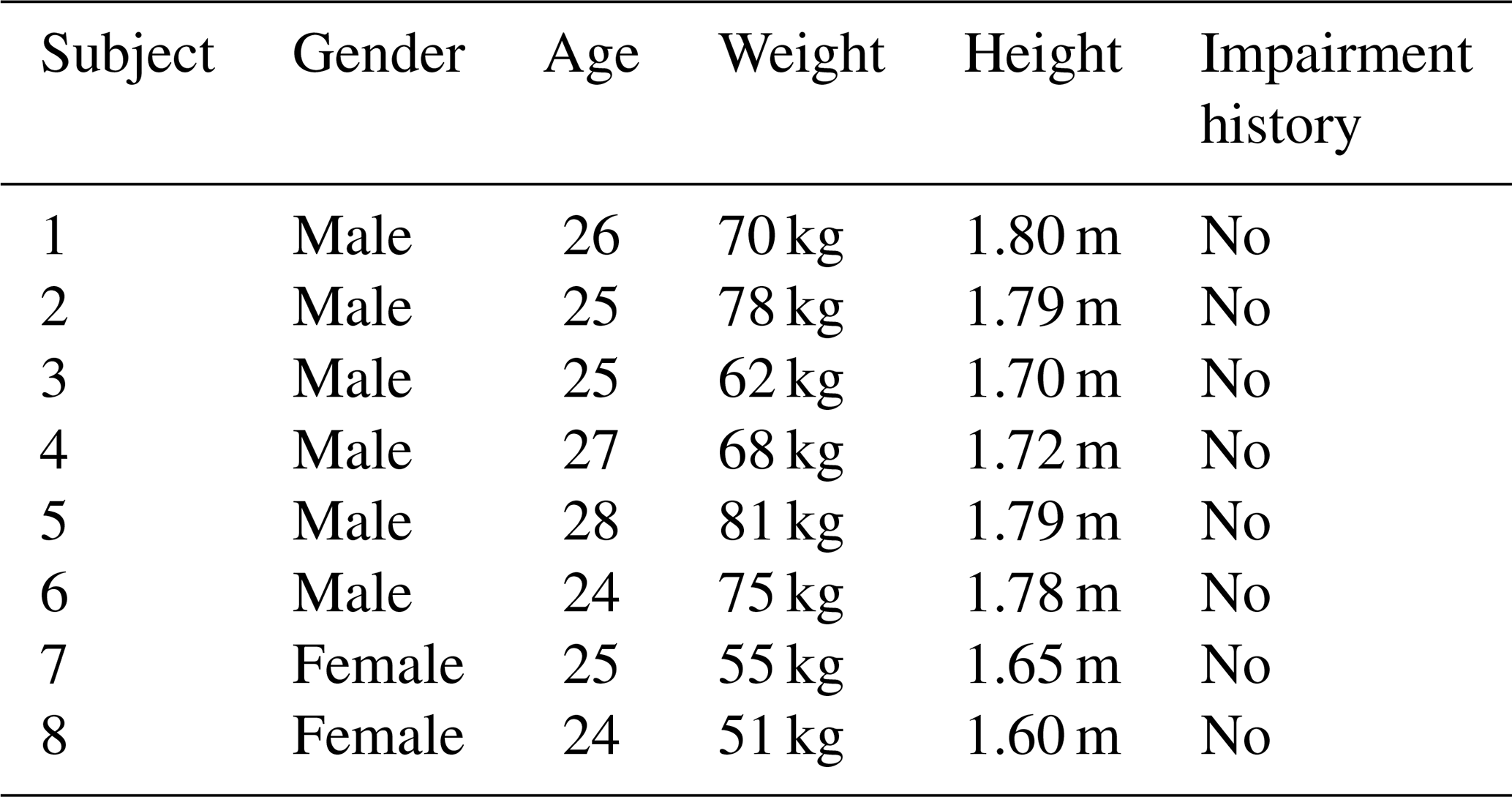
The experiments were performed on an end-effector upper-limb rehabilitation robot with 6 degrees of freedom. The main objective of the experiment was to validate and evaluate the feasibility of the proposed motor-trend-based rehabilitation strategy and to analyze the performance of the control system when the patients were in different stages of rehabilitation. In this experiment, eight able-bodied subjects (six males and two females, average age (mean 25.50 years, standard deviation (SD) 1.4142), weight (67.5 kg, SD 10.7836), and height (1.7288 m, SD 0.0745)) were recruited. Details of these subjects are shown in Table 2.
Table 2Details of five able-bodied subjects recruited for the evaluation experiments.
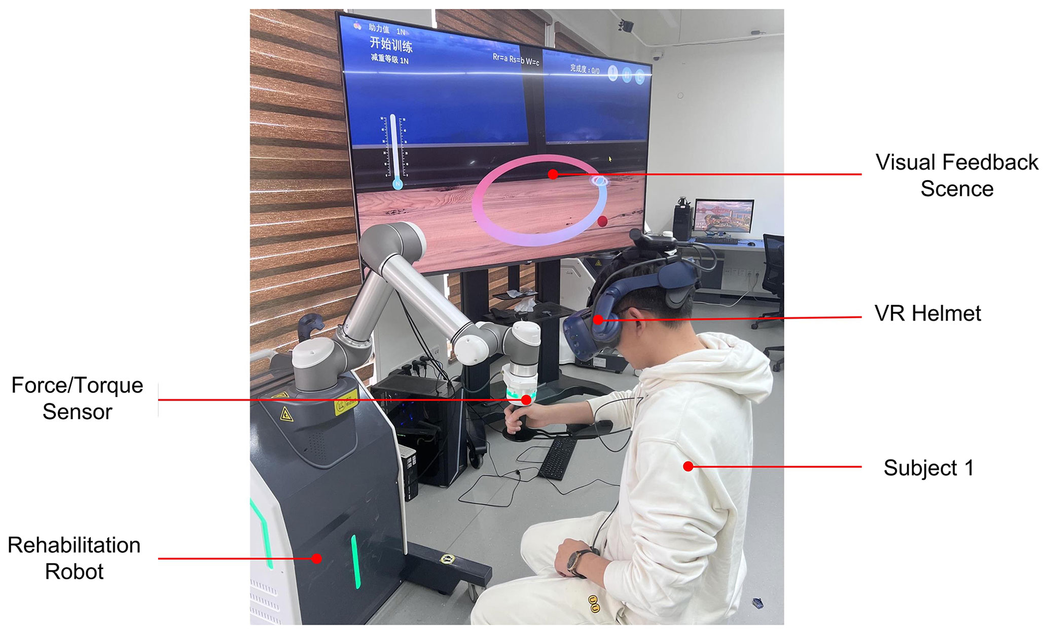
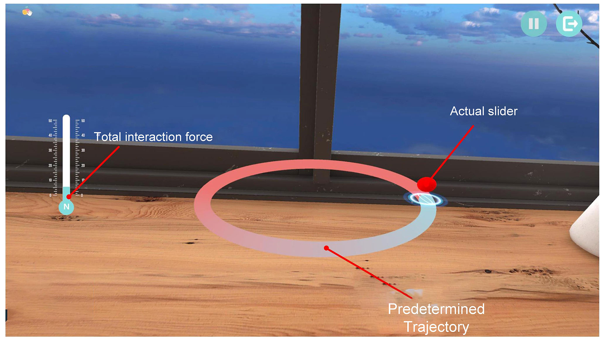
This study was approved by the ethics committee of the Yueyang Hospital of Integrated Traditional Chinese and Western Medicine. We assumed that the right arm of the subject was used during the experiment. Written informed consent was collected from all subjects before participation in this study. During the experiment, subjects were required to wear a virtual reality (VR) helmet and hold the robot end handle by placing their forearms on the robot's end handle holder, as shown in Fig. 5. The subject's training task was to follow a specified three-dimensional spatial trajectory. In the experiment, the trajectory of its 3D space is defined as a circle in space, and the center and radius of the circle are (0 m, 500 mm, −50 mm) and 120 mm, respectively. In addition, we developed a Unity-based visual 3D feedback scene to help subjects perceive spatial trajectories, as shown in Fig. 6. The red ball represents the hand position, the red curve represents the intended target trajectory, and the display bar on the left side represents the value of the combined force of the interaction.
To verify the effectiveness of the control strategy designed in this paper at different rehabilitation stages and the performance of the control system, here the subjects were asked to complete a total of six revolutions of the trajectory. During the first two laps, subjects were asked to actively follow the trajectory, occasionally with appropriately large deviations, to simulate a situation in which the subject's arm performance was excellent (active). In the third and fourth laps, subjects were required to deviate from the target trajectory with a larger force to simulate a situation of poor motor performance of the subject (poor). In the fifth and sixth laps, subjects were required to completely relax, and the robot drove the patient's arm through movements to simulate muscle weakness (slacking). The detailed parameters of the proposed control strategy in the experiment are shown in Table 3.
Before experimenting, subjects were able to perform some simple tasks until they became familiar with the upper-extremity rehabilitation robotic training system. Hardware and software safety protection was implemented to ensure the safety of the subjects during the experiments.
In the experiments, we collected and calculated the normal assistance force, tangential assistance force, and robot's motion trajectory data, and we processed the data by Gaussian low-pass filtering.
To allow for a better assessment of the subject's trajectory-following ability, here the mean trajectory deviation (MAE) is calculated as follows:
where N is the number of sampling points in the predetermined task. Similarly, to further analyze the normal assistance force and tangential assistance force provided by the robot, we define the average normal assistance force (ANAF) and average tangential assistance force (ATAF), respectively, as follows:
4.2 Results
The green channel and the red channel in Fig. 7 represent the virtual force field region boundaries of the first and second layers, respectively. Where the green, blue, and black curves represent the trajectory of subject 1 in the active, poor, and slacking states, respectively, and the red curve represents the intended trajectory. The subject's motion trajectories in the first two laps were mainly inside the red channel; in the middle two laps, they were mainly concentrated at the boundary outside the red channel. In the last two laps, it was mainly directly below the target trajectory.
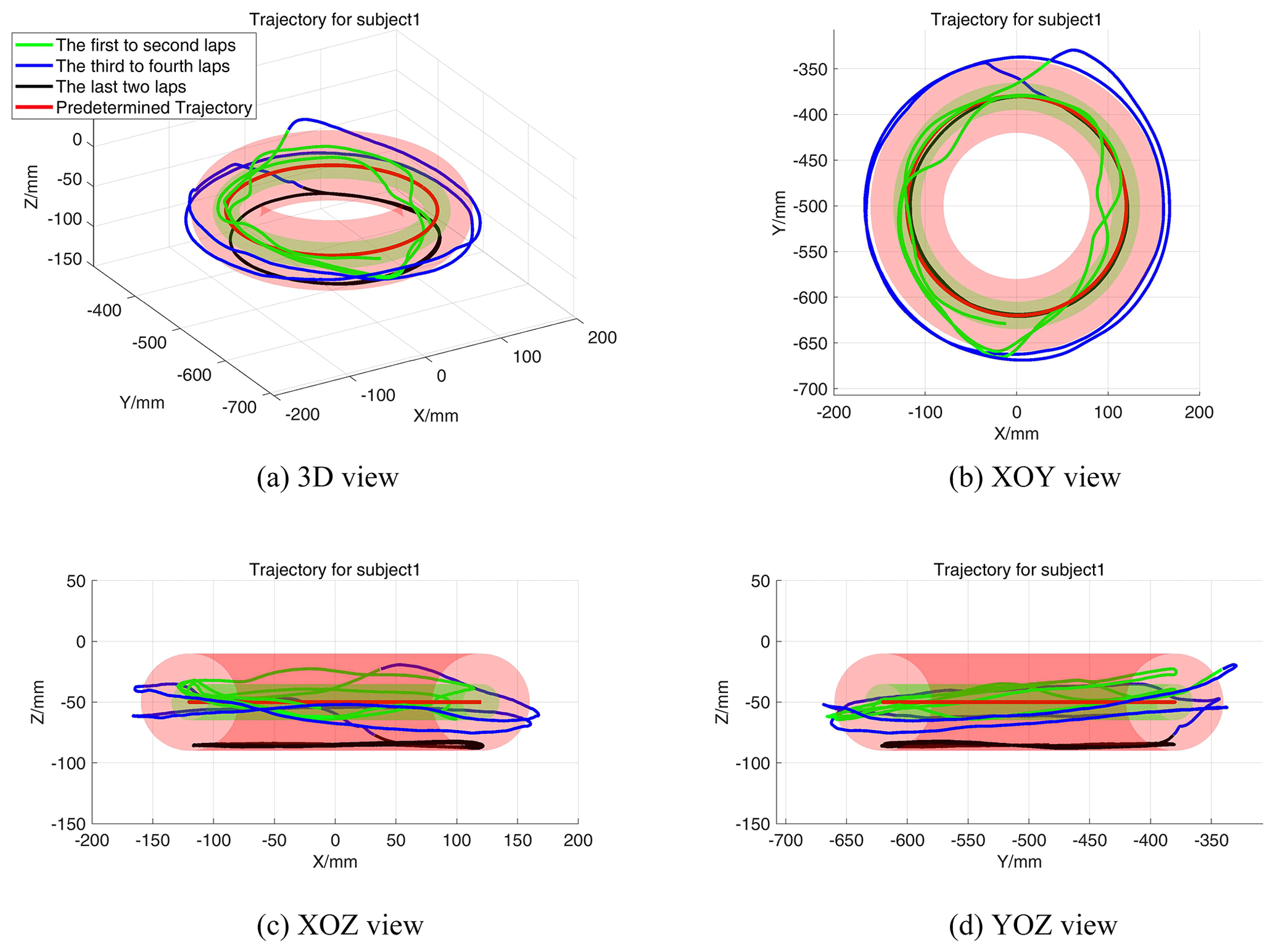
Figure 7Motion trajectories of subject 1 during the experiment. (a) Motion trajectory in 3D view; (b) motion trajectory in XOY view; (c) motion trajectory in XOZ view; (d) motion trajectory in YOZ view.
Figure 8a shows the relationship between the trajectory deviation and the normal assistance force of subject 1, and Fig. 8b shows the variation curve of the normal force field strength coefficient Kani. The green and red dotted lines represent the switching boundaries of the normal assistance force field, respectively. Consistent with the results in Fig. 7, in the first two laps (active), the trajectory deviations are mainly under the second virtual region boundary, where the normal stiffness coefficients and assistance forces were small. In the middle two laps (poor), the trajectory deviation exceeds Rm, and the assistance force and Kani were larger. In the last two turns (slacking), the trajectory deviation, assistance force, and Kani were maintained in a range of values. In addition, the normal assistance force and Kani decreased rapidly at the end of the middle two laps.
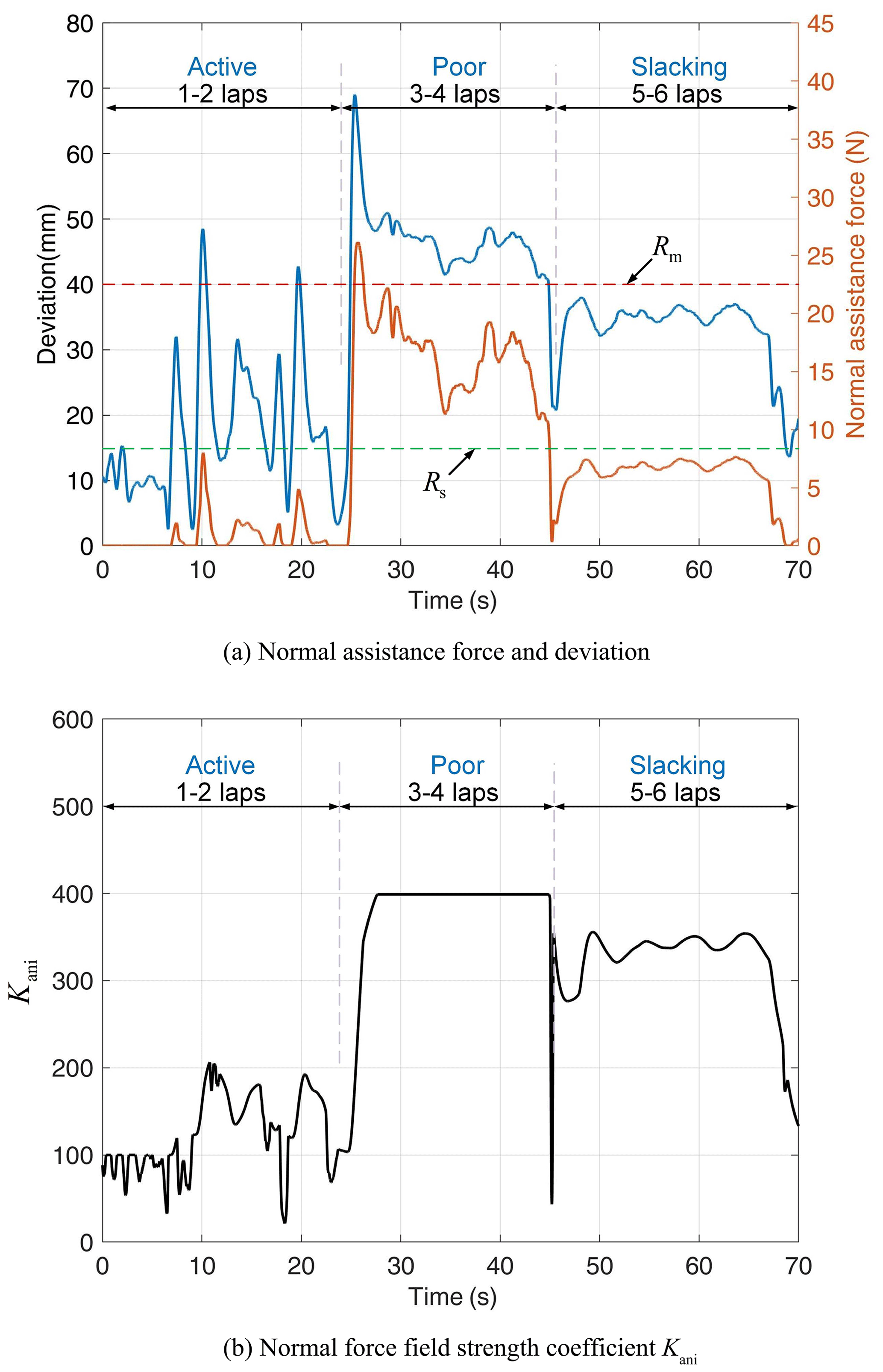
Figure 8Normal force field assistance performance of subject 1. (a) Normal assistance force and trajectory-tracking deviation; (b) normal force field strength coefficient Kani.
Figure 9a shows the relationship between the tangential interaction force and the tangential assistance force of subject 1 during the experiment, and Fig. 9b shows the variation curve of the tangential force field strength coefficient Kati. Under the first to fourth laps (active and poor), the Kati values are almost zero; in the last two laps, the tangential interaction force fluctuates slightly around 0 N, and the tangential assistance force and Kati reach a maximum at this stage. In addition, at the end of the experiment, the tangential assistance force and Kati decrease rapidly.
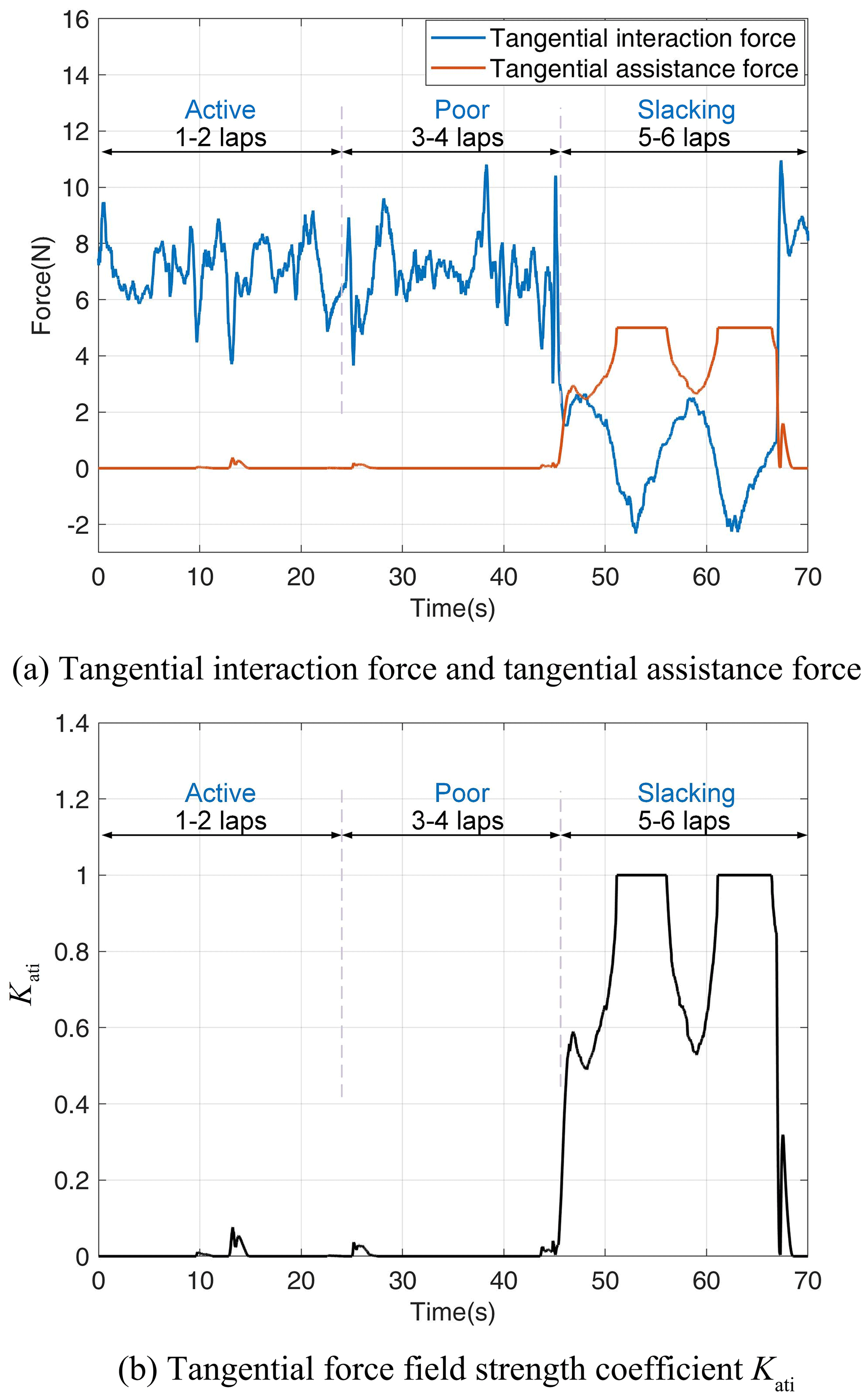
Figure 9Tangential force field assisted performance. (a) Tangential assistance force and subject's tangential interaction force; (b) tangential assistance force field strength coefficient Kati.
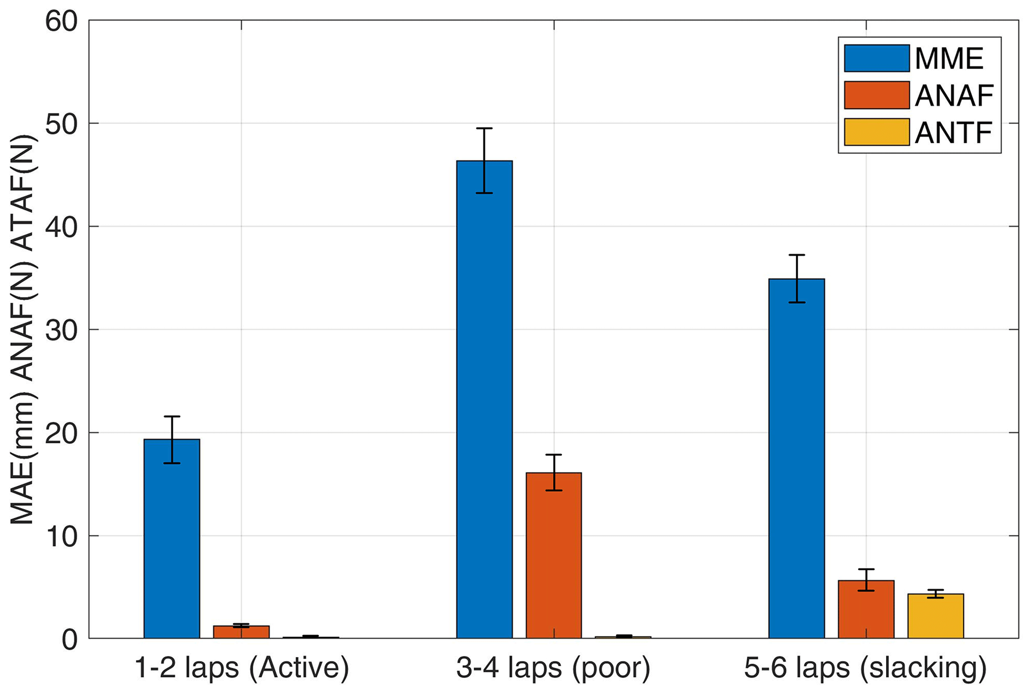
Figure 10 displays the mean and standard deviation of MAE, ANAF, and ATAF of eight healthy subjects in the first two laps (active), third to fourth laps (poor), and final two laps (slacking). The mean MAE, ANAF, and ATAF of the three subjects were 19.3383 mm (SD: 4.4170 mm), 1.2098 N (SD: 0.2888 N), and 0.1415 N (SD: 0.0525 N) in the first two laps; 46.3379 mm (SD: 6.6120 mm), 16.0966 N (SD: 3.7407 N), and 0.1675 N (SD: 0.0783 N) in the third to fourth laps; and 34.8901 mm (SD: 3.9886 mm), 5.6494 N (SD: 1.9739 N), and 4.3244 N (SD: 0.4299 N), respectively, in the final two laps.
In this paper, a motion-trend-based assistance control strategy for an upper-limb rehabilitation robot is proposed, which includes adaptive assistance force fields in two directions. In addition, the performance of the control strategy was preliminarily verified and evaluated through a series of experiments with eight healthy subjects.
The above experiment analyzed the performance of the control strategy by analyzing the performance of eight subjects in different states. During the active phase, the average MAE, ANAF, and ATAF values were 19.3383 mm, 1.2098 N, and 0.1415 N, respectively (as shown in Fig. 10). It indicates that the two directions provide less assistance and that the tangential assistance force is almost zero. In the case of normal-assisted force, most of the subject's motion trajectory deviations are concentrated under the virtual boundary Rs, when the normal-assisted force is 0 N. Even if it occasionally exceeds the virtual boundary Rs , its normal assistance force is small and does not increase rapidly (as shown in Fig. 8a). Its normal force field strength coefficient Kani is mostly below 200 (as shown in Fig. 8b). For the tangential assistance case, the tangential assistance force provided by the robot and the tangential force-field strength coefficient Kati is almost zero, since the tangential interaction force is mostly larger than the maximum tangential assistance force (as shown in Fig. 9). The above results indicate that the robot intervention is very small when the subject is actively moving and can filter out excessive assistance forces due to perturbations, which allows the subject to have better initiative.
During the poor phase, the average MAE, ANAF, and ATAF values were 46.3379 mm, 16.0966 N, and 0.1675 N, respectively (as shown in Fig. 10). This indicates that the mean normal assistance force and the mean trajectory deviation are large, while the mean tangential assistance force is almost zero. For the case of normal assistance, at the beginning, the subject was actively moving out of the trajectory, and the trajectory deviation increased to 69.5 mm and finally stabilized at about 45 mm (as shown in Fig. 8a). The normal force field strength coefficient Kani is also gradually increased to 400 and remains at its maximum value for a subsequent period when maximum normal assistance is provided (as shown in Fig. 8b). In addition, the trajectory deviation gradually decreases at 44.9 s when the subject is actively converging to the trajectory motion. At this point, the normal assistance force provided by the robot decreases rapidly and decreases directly to 0 N before the subject reaches the virtual boundary Rs, providing no assistance to the subject (as shown in Fig. 8a). Similarly, Kani decreases rapidly to zero until the subject does not actively converge on the trajectory. At this point, the normal motion trend coefficients β do not work, and Kani values rebound quickly and are followed by slow changes influenced only by the normal integrated motion state indicator Incm (as shown in Fig. 8b). For the tangential motion and assistance cases, which are the same here as for the subject in the 1–2 lap motion case, the robotic system provides little tangential assistance force (as shown in Fig. 9a). Similarly, the tangential force field strength coefficient Kati is smaller (as shown in Fig. 9b).
The above results indicate that when the subject's motion performance was consistently poor, the control system gradually increased the assistance level to provide a larger normal assistance force to limit the subject's motion toward the outside of the trajectory. And when the subject has a trend toward good motor performance, the control system can quickly reduce the assistance force.
During the slacking phase, the average MAE, ANAF, and ATAF values were 34.8901 mm, 5.6494 N, and 4.3244 N, respectively (as shown in Fig. 10). This indicates that the robot provides some normal and tangential assistance.
For the case of normal assistance, the robot provided normal assistance because the subject was in a relaxed state and the subject's arm naturally drops with a certain weight, and the robot needed to provide normal assistance to balance the arm's weight. Similarly, we can see from Fig. 7 that the motion trajectory in this phase is mainly concentrated below the target trajectory. In addition, the tangential interaction force fluctuates around 0 N, with a maximum of 2.32 N and a minimum of −2.16 N (as shown in Fig. 9a). This is because the subject is dragged by the robot in a circular motion, and in a completely relaxed state the end force of the subject's arm changes slightly with the position of the limb joint where it is located. For the tangential motion and assistance cases, as the subject's tangential interaction force decreases until it reaches about 0 N, the tangential assistance force increases slowly to about 4 N. Similarly, the tangential force field strength coefficient Kati increases gradually from zero to one, providing the maximum tangential assistance to drive the subject's arm. At 66 s, the tangential assistance force and the tangential assistance coefficient Kati drop rapidly to 0 N and 0, respectively (as shown in Fig. 9). Similarly, this is due to the subject's active motion, and the tangential motion trend coefficient decreases, causing a rapid decrease in the tangential assistance force field. The above results demonstrate that the control system provides a tangential assistance force that varies with the subject's tangential interaction force to drive the subject's arm when the subject moves without force. And when the subject moves actively, the assistance is rapidly reduced.
Traditional rehabilitation training assistance control strategies generally adjust robot assistance by basing control on performance indexes such as motion deviation. The control strategy proposed in this paper additionally introduces motion trend indexes on this basis and can provide adaptive assisted control in the normal and tangential directions. In the normal direction, the strength of the normal force field is changed in real time according to the subject's motion deviation and normal motion trend; in the tangential direction, the strength of the tangential force field is changed in real time according to the subject's tangential interaction force and tangential motion trend. And additionally, by introducing coefficients determined by the motion trend in each of the two directions, the assistance force field strength can be reduced quickly when the motion trend is positive. Based on the above experimental analysis, it can be seen that the normal assistance force in the active motion phase is 92.48 % smaller than that in the poor phase and that the tangential assistance force in the active phase is 90.73 % smaller than that in the slack phase. This suggests that the control system can quickly and adaptively provide assistance based on the subject's motor performance to meet the assistance needs of different motor states. In addition, it can be seen from the graph of assistance force change that when the subject has a good motion trend, the normal assistance force or tangential assistance force will change to zero within 0.2 s. This indicates that the assistance force can decrease rapidly when the subject has a good motion trend. The control system provides little or no assistance in the normal and tangential directions during the normal motion phase and reduces the effect of sudden disturbances that cause the assistance force to increase rapidly, allowing the subject to have better active motion when performance is positive. During the poor phase, the strength of the assistance force field of its control system gradually increases with the subject's performance, providing a strong assistance force field that restricts the subject's movement away from the target trajectory. As the subject tends to move toward the target trajectory, the control system can quickly reduce the assistance force without facilitating the subject's movement toward the inside of the trajectory. In the slack phase, the tangential assistance force field gradually increases, driving the subject to perform rehabilitation movements, and the tangential assistance force rapidly decreases when the subject is actively moving.
In this paper, a motion-trend-based robot assistance control strategy is proposed to provide adaptive assistance control in the normal and tangential directions, which can quickly adjust the normal and tangential assistance levels according to the subject's motion performance and quickly reduce the assistance when the motion trend is positive. To validate and evaluate the performance of the control strategy, we recruited eight able-bodied subjects to conduct experiments based on an end-effector robot in three different states. Preliminary experimental results show that the proposed motor-trend-based assistance control strategy works well. It changes the level of assistance according to the subject's motor performance to adapt to different rehabilitation stages and rapidly reduces the assistance force when the subject's motor trend becomes better. This control strategy encourages subjects to actively participate in rehabilitation training.
Future work will incorporate OpenSim to develop a pathway suitable for the subject's arm rehabilitation and recruit patients for further trials.
The data that support the findings of this study are available from the corresponding author upon reasonable request.
HZ and TG conceived the idea. HZ wrote and debugged the experimental code. HZ drafted the paper; LZ and HZ discussed and edited the paper. HZ finalized the paper. TG provided financial and project support for the experiment.
The contact author has declared that none of the authors has any competing interests.
Publisher's note: Copernicus Publications remains neutral with regard to jurisdictional claims made in the text, published maps, institutional affiliations, or any other geographical representation in this paper. While Copernicus Publications makes every effort to include appropriate place names, the final responsibility lies with the authors.
The authors are grateful to the anonymous reviewers and the editor for their comments and suggestions on improving our paper.
This research has been supported by the Science and Technology Commission of Shanghai Municipality (grant no. 21SQBS00300), National Natural Science Foundation of China (grant no. 82227807), Special Fund for Digital Transformation of Shanghai (grant no. 202202004), and Open Project of the Medical and Industrial Integration Laboratory of Jiangning Hospital Affiliated to Nanjing Medical University (grant no. JNYYZXKY202218).
This paper was edited by Med Amine Laribi and reviewed by two anonymous referees.
Asl, H. J., Yamashita, M., Narikiyo, T., and Kawanishi, M.: Field-Based Assist-as-Needed Control Schemes for Rehabilitation Robots, IEEE-ASME T. Mech., 25, 2100–2111, https://doi.org/10.1109/tmech.2020.2992090, 2020.
Babaiasl, M., Mahdioun, S. H., Jaryani, P., and Yazdani, M.: A review of technological and clinical aspects of robot-aided rehabilitation of upper-extremity after stroke, Disability and rehabilitation: Assistive Technology, 11, 263–280, https://doi.org/10.3109/17483107.2014.1002539, 2016.
Battiston, B., Titolo, P., Ciclamini, D., and Panero, B.: Peripheral Nerve Defects Overviews of Practice in Europe, Hand Clin., 33, 545–550, https://doi.org/10.1016/j.hcl.2017.04.005, 2017.
Cao, R., Cheng, L., Yang, C. G., and Dong, Z.: Iterative assist-as-needed control with interaction factor for rehabilitation robots, Science China Technological Sciences, 64, 836–846, https://doi.org/10.1007/s11431-020-1671-6, 2021.
Chang, W. H. and Kim, Y.-H.: Robot-assisted Therapy in Stroke Rehabilitation, J. Stroke, 15, 174–181, https://doi.org/10.5853/jos.2013.15.3.174, 2013.
Frullo, J. M., Elinger, J., Pehlivan, A. U., Fitle, K., Nedley, K., Francisco, G. E., Sergi, F., and O'Malley, M. K.: Effects of Assist-As-Needed Upper Extremity Robotic Therapy after Incomplete Spinal Cord Injury: A Parallel-Group Controlled Trial, Front. Neurorobotics, 11, 26, https://doi.org/10.3389/fnbot.2017.00026, 2017.
Gassert, R. and Dietz, V.: Rehabilitation robots for the treatment of sensorimotor deficits: a neurophysiological perspective, J. Neuroeng. Rehabil., 15, 46, https://doi.org/10.1186/s12984-018-0383-x, 2018.
Guo, Y. D., Wang, H. P., Tian, Y., and Caldwell, D. G.: Task performance-based adaptive velocity assist-as-needed control for an upper limb exoskeleton, Biomed. Signal Proces., 73, 103474, https://doi.org/10.1016/j.bspc.2021.103474, 2022.
Hatem, S. M., Saussez, G., della Faille, M., Prist, V., Zhang, X., Dispa, D., and Bleyenheuft, Y.: Rehabilitation of Motor Function after Stroke: A Multiple Systematic Review Focused on Techniques to Stimulate Upper Extremity Recovery, Front. Hum. Neurosci., 10, 442, https://doi.org/10.3389/fnhum.2016.00442, 2016.
Houwink, A., Nijland, R. H., Geurts, A. C., and Kwakkel, G.: Functional Recovery of the Paretic Upper Limb After Stroke: Who Regains Hand Capacity?, Arch. Phys. Med. Rehab., 94, 839–844, https://doi.org/10.1016/j.apmr.2012.11.031, 2013.
Jiang, J. W., Guo, S., Zhang, L. G., and Sun, Q.: Motor Ability Evaluation of the Upper Extremity with Point-To-Point Training Movement Based on End-Effector Robot-Assisted Training System, J. Healthc. Eng., 2022, 1939844, https://doi.org/10.1155/2022/1939844, 2022.
Krebs, H. I., Ferraro, M., Buerger, S. P., Newbery, M. J., Makiyama, A., Sandmann, M., Lynch, D., Volpe, B. T., and Hogan, N.: Rehabilitation robotics: pilot trial of a spatial extension for MIT-Manus, J. Neuroeng. Rehabil., 1, 5–5, https://doi.org/10.1186/1743-0003-1-5, 2004.
Kwakkel, G., Kollen, B. J., and Krebs, H. I.: Effects of robot-assisted therapy on upper limb recovery after stroke: A systematic review, Neurorehab. Neural Re., 22, 111–121, https://doi.org/10.1177/1545968307305457, 2008.
Leconte, P. and Ronsse, R.: Performance-based robotic assistance during rhythmic arm exercises, J. Neuroeng. Rehabil., 13, 82, https://doi.org/10.1186/s12984-016-0189-7, 2016.
Li, X., Zeng, H., Zhang, J. X., and Song, A. G.: Engagement Enhancement Based on Bayesian Optimization for Adaptive Assist-as-Needed Controller, Ieee Robotics and Automation Letters, 7, 49–56, https://doi.org/10.1109/lra.2021.3118473, 2022.
Lin, C. H., Su, Y. Y., Lai, Y. H., and Lan, C. C. E.: A Spatial-Motion Assist-as-Needed Controller for the Passive, Active, and Resistive Robot-Aided Rehabilitation of the Wrist, IEEE Access, 8, 133951–133960, https://doi.org/10.1109/access.2020.3010564, 2020.
Loureiro, R., Amirabdollahian, F., Topping, M., Driessen, B., and Harwin, W.: Upper limb robot mediated stroke therapy – GENTLE/s approach, Auton. Robot., 15, 35–51, https://doi.org/10.1023/a:1024436732030, 2003.
Luo, L., Peng, L., Hou, Z., and Wang, W.: An Adaptive Impedance Controller for Upper Limb Rehabilitation Based on Estimation of Patients' Stiffness, IEEE International Conference on Robotics and Biomimetics (ROBIO), Macau, Macao, 5–8 December 2017, WOS:000576754200087, IEEE, 532–537, https://doi.org/10.1109/ROBIO.2017.8324471, 2017.
Luo, L., Peng, L., Wang, C., and Hou, Z.-G.: A Greedy Assist-as-Needed Controller for Upper Limb Rehabilitation, Ieee Transactions on Neural Networks and Learning Systems, 30, 3433-3443, https://doi.org/10.1109/tnnls.2019.2892157, 2019.
Milot, M.-H., Spencer, S. J., Chan, V., Allington, J. P., Klein, J., Chou, C., Bobrow, J. E., Cramer, S. C., and Reinkensmeyer, D. J.: A crossover pilot study evaluating the functional outcomes of two different types of robotic movement training in chronic stroke survivors using the arm exoskeleton BONES, J. Neuroeng. Rehabil., 10, 112, https://doi.org/10.1186/1743-0003-10-112, 2013.
Mounis, S. Y. A., Azlan, N. Z., and Sado, F.: Assist-as-needed control strategy for upper-limb rehabilitation based on subject's functional ability, Meas. Control, 52, 1354–1361, https://doi.org/10.1177/0020294019866844, 2019.
Mounis, S. Y. A., Azlan, N. Z., and Sado, F.: Assist-as-Needed Robotic Rehabilitation Strategy Based on z-Spline Estimated Functional Ability, IEEE Access, 8, 157557–157571, https://doi.org/10.1109/access.2020.3019450, 2020.
Muratori, L. M., Lamberg, E. M., Quinn, L., and Duff, S. V.: Applying principles of motor learning and control to upper extremity rehabilitation, J. Hand Ther., 26, 94–102, https://doi.org/10.1016/j.jht.2012.12.007, 2013.
Nef, T., Guidali, M., and Riener, R.: ARMin III – Arm Therapy Exoskeleton with an Ergonomic Shoulder Actuation, Appl. Bionics Biomech., 6, 962956, https://doi.org/10.1080/11762320902840179, 2009.
Pan, J., Zhang, L., and Sun, Q.: Development of a force-field-based control strategy for an upper-limb rehabilitation robot, Mech. Sci., 13, 949–959, https://doi.org/10.5194/ms-13-949-2022, 2022.
Papaleo, E., Zollo, L., Spedaliere, L., and Guglielmelli, E.: Patient-Tailored Adaptive Robotic System for Upper-Limb Rehabilitation, IEEE International Conference on Robotics and Automation (ICRA), Karlsruhe, Germany, 6–10 May 2013, WOS:000337617303129, IEEE, 3860–3865, https://doi.org/10.1109/ICRA.2013.6631120, 2013.
Pehlivan, A. U., Losey, D. P., and O'Malley, M. K.: Minimal Assist-as-Needed Controller for Upper Limb Robotic Rehabilitation, IEEE T. Robot., 32, 113–124, https://doi.org/10.1109/TRO.2015.2503726, 2016.
Peng, L., Wang, C., Luo, L., Chen, S., Hou, Z.-G., and Wang, W.: A CPG-Inspired Assist-As-Needed Controller for an Upper-Limb Rehabilitation Robot, 8th IEEE Symposium Series on Computational Intelligence (IEEE SSCI), Bengaluru, India, 18–21 November 2018, WOS:000459238800307, IEEE, 2200–2206, https://doi.org/10.1109/SSCI.2018.8628896, 2018.
Pilutti, L. A., Lelli, D. A., Paulseth, J. E., Crome, M., Jiang, S., Rathbone, M. P., and Hicks, A. L.: Effects of 12 Weeks of Supported Treadmill Training on Functional Ability and Quality of Life in Progressive Multiple Sclerosis: A Pilot Study, Arch. Phys. Med. Rehab., 92, 31–36, https://doi.org/10.1016/j.apmr.2010.08.027, 2011.
Proietti, T., Crocher, V., Roby-Brami, A., and Jarrasse, N.: Upper-Limb Robotic Exoskeletons for Neurorehabilitation: A Review on Control Strategies, IEEE Reviews in Biomedical Engineering, 9, 4–14, https://doi.org/10.1109/rbme.2016.2552201, 2016.
Ruffaldi, E., Barsotti, M., Leonardis, D., Bassani, G., Frisoli, A., and Bergamasco, M.: Evaluating Virtual Embodiment with the ALEx Exoskeleton, 9th International Conference on Haptics - Neuroscience, Devices, Modeling, and Applications (EuroHaptics), Versailles, France, 24–27 June 2014, EuroHaptics: International Conference on Human Haptic Sensing and Touch Enabled Computer Applications, WOS:000350868900018, 133–140, https://doi.org/10.1007/978-3-662-44193-0_18, 2014.
Sawner, K. A., Brunnstrom, S., and Vigne, J. M.: Brunnstrom's Movement Therapy in Hemiplegia: A Neurophysiological Approach, https://doi.org/10.1093/geronj/27.2.290, 1992.
Sugar, T. G., He, J., Koeneman, E. J., Koeneman, J. B., Herman, R., Huang, H., Schultz, R. S., Herring, D. E., Wanberg, J., Balasubramanian, S., Swenson, P., and Ward, J. A.: Design and control of RUPERT: A device for robotic upper extremity repetitive therapy, IEEE T. Neur. Sys. Reh., 15, 336–346, https://doi.org/10.1109/tnsre.2007.903903, 2007.
Taheri, H., Reinkensmeyer, D. J., and Wolbrecht, E. T.: Model-Based Assistance-as-Needed for Robotic Movement Therapy after Stroke, in: 38th Annual International Conference of the IEEE Engineering in Medicine and Biology Society (EMBC), Orlando, FL, USA, 16–20 August 2016, WOS:000399823502122, IEEE, 2124–2127, https://doi.org/10.1109/EMBC.2016.7591148, 2016.
Tucker, M. R., Olivier, J., Pagel, A., Bleuler, H., Bouri, M., Lambercy, O., Millan, J. d. R., Riener, R., Vallery, H., and Gassert, R.: Control strategies for active lower extremity prosthetics and orthotics: a review, J. Neuroeng. Rehabil., 12, 1, https://doi.org/10.1186/1743-0003-12-1, 2015.
Vergaro, E., Casadio, M., Squeri, V., Giannoni, P., Morasso, P., and Sanguineti, V.: Self-adaptive robot training of stroke survivors for continuous tracking movements, J. Neuroeng. Rehabil., 7, 13, https://doi.org/10.1186/1743-0003-7-13, 2010.
Wang, C., Peng, L., Hou, Z.-G., Wang, W., and Su, T.: A Novel Assist-As-Needed Controller Based on Fuzzy-Logic Inference and Human Impedance Identification for Upper-Limb Rehabilitation, IEEE Symposium Series on Computational Intelligence (SSCI), Xiamen, China, 6–9 December 2019, WOS:000555467201034, IEEE, 1133–1139, https://doi.org/10.1109/SSCI44817.2019.9002868, 2019.
Xu, Z. Y., Guo, S., and Zhang, L. G.: A path planning method of 6-DOF robot for mirror therapy based on A* algorithm, Technol. Health Care, 30, 105–116, https://doi.org/10.3233/thc-202551, 2022.
Zhang, L., Guo, S., and Sun, Q.: Development and Assist-As-Needed Control of an End-Effector Upper Limb Rehabilitation Robot, Appl. Sci.-Basel, 10, 6684, https://doi.org/10.3390/app10196684, 2020.
Zhang, L., Guo, S., and Xi, F.: Performance-based assistance control for robot-mediated upper-limbs rehabilitation, Mechatronics, 89, 102919, https://doi.org/10.1016/j.mechatronics.2022.102919, 2023.
Zhang, L. G., Guo, S., and Sun, Q.: DEVELOPMENT AND ANALYSIS OF A BILATERAL END-EFFECTER UPPER LIMB REHABILITATION ROBOT, J. Mech. Med. Biol., 21, 2150032, https://doi.org/10.1142/s0219519421500329, 2021.
- Abstract
- Introduction
- Description and conductive control of an upper-limb rehabilitation robot
- Assistance control strategy based on motion trend
- Experiments and results
- Discussion
- Conclusion
- Data availability
- Author contributions
- Competing interests
- Disclaimer
- Acknowledgements
- Financial support
- Review statement
- References