the Creative Commons Attribution 4.0 License.
the Creative Commons Attribution 4.0 License.
 | 29 Sep 2023
Assembly of reconfigurable Bricard-like mechanisms to form a multimode deployable arch
Ruiming Li
Xianhong Zhang
Shuo Zhang
Ran Liu
Yan-an Yao
This paper deals with the construction of a novel family of multimode deployable mechanisms based on reconfigurable Bricard-like mechanisms. By connecting a number of identical threefold-symmetric (TFS) Bricard-like mechanisms, a multimode deployable arch is proposed for the first time, which can switch between the scissor-like deployable mode and the arch deformable mode through the transition configuration. Then new multimode center-driven deployable mechanisms can be obtained by connecting three and six multimode deployable arches. The obtained mechanism can switch between the scissor-like deployable mode and spherical deformable mode, and it can be reassembled by adjusting the number of TFS Bricard-like mechanisms to change its size. Finally, physical prototypes of the multimode deployable arch and multimode center-driven deployable mechanisms are fabricated and tested to validate the feasibility of the proposed approach and analysis.
- Article
(15670 KB) - Full-text XML
-
Supplement
(20020 KB) - BibTeX
- EndNote


Deployable mechanisms have aroused great interest in many researchers in the past few decades due to their potential applications in aerospace engineering (Puig et al., 2010). Currently, most deployable mechanisms are constructed with scissor-like elements (SLEs) and angulated elements (AEs) (Escrig, 1985; You and Pellegrino, 1997; Wohlhart, 2004; Kiper et al., 2008; Hoberman, 2008; Zhao et al., 2009; Bai et al., 2013; Huang et al., 2019).
The above research studies mainly focus on planar SLEs and AEs. Besides, some deployable mechanisms based on other novel units were also presented. Deng et al. (2011) presented a geometric approach for the design and synthesis of deployable single-loop mechanisms with pure revolute joints. Ding et al. (2013) proposed a new prism deployable mechanism based on polyhedral linkages that possesses half-closed polyhedron characteristics. Cao et al. (2020, 2021) established a method for kinematic analysis of two-layer and two-loop deployable linkages with coupling chains and presented a new double-ring truss-deployable satellite antenna mechanism. Cheng et al. (2021) constructed a novel family of umbrella-shaped deployable mechanisms based on new multi-layer and multi-loop spatial deployable linkage units. Wang et al. (2022) presented a novel three-limb deployable mechanism using a set of metamorphic mechanism modules. Guo et al. (2022) designed a truss-deployable antenna mechanism based on the 3RR-3URU tetrahedral unit.
In addition to that, spatial single-loop over-constrained linkages are also widely used in deployable mechanisms. Bennett (1903, 1914) proposed a Bennett linkage with 4R joints, and many 5R or 6R over-constrained mechanisms were constructed on the basis of the Bennett linkage (Myard, 1931; Goldberg, 1943; Song and Chen, 2012; Ma et al., 2018). Then Bricard (1897, 1926) discovered six types of Bricard linkages. By analyzing and adjusting geometric parameters of Bricard linkages, Chen et al. (2005) presented a threefold-symmetric (TFS) Bricard linkage. Owing to the property of good folding performance of single-loop over-constrained linkages, the networking method has become an important construction method of deployable mechanisms. Chen and You (2008b, a) proposed deployable structures formed by interconnected Bennett linkages and constructed a large-scale deployable assembly by connecting many 6R linkages derived from an extended Myard linkage. Viquerat et al. (2013) designed a deployable structure that deploys from a compact bundle to a rectangular ring. Qi et al. (2017) constructed large deployable mechanisms by connecting several plane-symmetric Bricard linkages. Lu et al. (2019, 2020) presented a family of mechanisms by using the capability of the type III Bricard linkage to be coplanar in two configurations and constructed a network of type III Bricard linkages. Yang et al. (2020) proposed a method to design general deployable hexagonal structures based on alternative forms of TFS Bricard linkages. Song et al. (2020, 2021) proposed a mobility analysis method using screw theory and constructed a series of mechanical networks with TFS Bricard linkages.
However, the deployable mechanism composed of the above units usually has only one mode of motion. To improve the adaptability and flexibility of the deployable mechanism, many reconfigurable mechanisms known as metamorphic mechanisms (Dai and Rees Jones, 1999; Li et al., 2011) and multiple operation mode mechanisms (Kong, 2013) have been emerging in mechanism science and robotics. Wang and Kong (2018a, b) adopted the trihedral Bricard linkage with six identical links as the plane to form multimode deployable polyhedral mechanisms. In our previous studies, a series of construction methods for deployable mechanisms were presented (Li et al., 2016, 2017, 2018, 2019; Sun et al., 2020b, a, 2021). In Liu et al. (2020), a novel family of reconfigurable deployable Bricard-like mechanisms with angulated elements was proposed.
In this paper, we construct a multimode deployable arch by connecting a number of Bricard-like mechanisms. The obtained arch switches between the scissor-like deployable mode and the arch deformable mode through its transition configuration. Further, by connecting three and six identical arches, new multimode deployable mechanisms are proposed, and the obtained mechanism can switch between the scissor-like deployable mode and spherical deformable mode as well. Besides, they can be reassembled to change the size by adjusting the number of Bricard-like mechanisms.
This paper is organized as follows. Section 2 introduces a reconfigurable deployable Bricard-like mechanism with angulated elements. Then, the construction of a multimode deployable arch is explained. In Sect. 3, the assembly of the multimode deployable arch-derived mechanism is explained. And prototypes of the mechanisms are fabricated to verify the proposed construction method and reassembly feasibility of the mechanism in Sect. 4. Section 5 concludes the paper.
2.1 A reconfigurable deployable Bricard-like mechanism with angulated elements
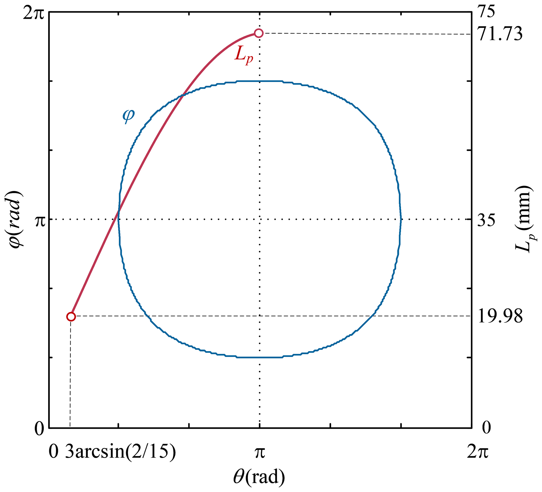
Based on the unequal diagonal angles of the angulated element (AE), a reconfigurable dual-AE unit is designed by articulating two AEs symmetrically at nodes A and B, as shown in Fig. 1a. Parameters of the dual-angulated-element unit satisfy that AC = AC′ = BC = BC′ = CD = CE = C′F = C′G = L and DH = EI = FJ = GK = l, where ∠BCD = ∠ACE = ∠AC′G = ∠BC′F is denoted by γ; the angle required to rotate BC clockwise to BC′ is defined as θ, and the diameter of each node is e. The obtained reconfigurable dual-AE unit has two motion modes: scissor-like deployable mode and rotation mode. In scissor-like deployable mode, the dual-AE unit can deploy as a scissor-like element, and the distance between the two axes Lp is calculated in Eq. (1) and described in Fig. 3.
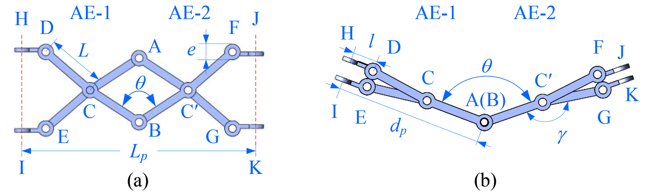
Figure 1The dual angulated elements unit with spatial RRR chains: (a) scissor-like deployable mode, (b) rotation mode.
When nodes A and B coincide with each other, the unit reaches its switching configuration; then the two angulated elements are equivalent to two rigid bars, and the dual AEs are in rotation mode. The dual-AE unit becomes two links connected by an R joint, which can make AE-2 rotate counterclockwise around AE-1. The link lengths of the unit are set as L, and the diameter of each node is e. In order to get a better folding effect and avoid linkage interference, the link angle γ of the AE is derived.
By connecting three dual-AE units with spatial RRR chains, a reconfigurable Bricard-like mechanism is constructed, as shown in Fig. 2c. In the RRR chain, the lengths of two links are equal; the axes of the adjacent R joints are perpendicular to each other; and the first and the third R joints are, respectively, parallel to the R joints of its articulated dual-AE unit. When nodes A and B coincide, R joints at nodes A and B will replace the virtual R joints to form the Bricard linkage, as shown in Fig. 2d.
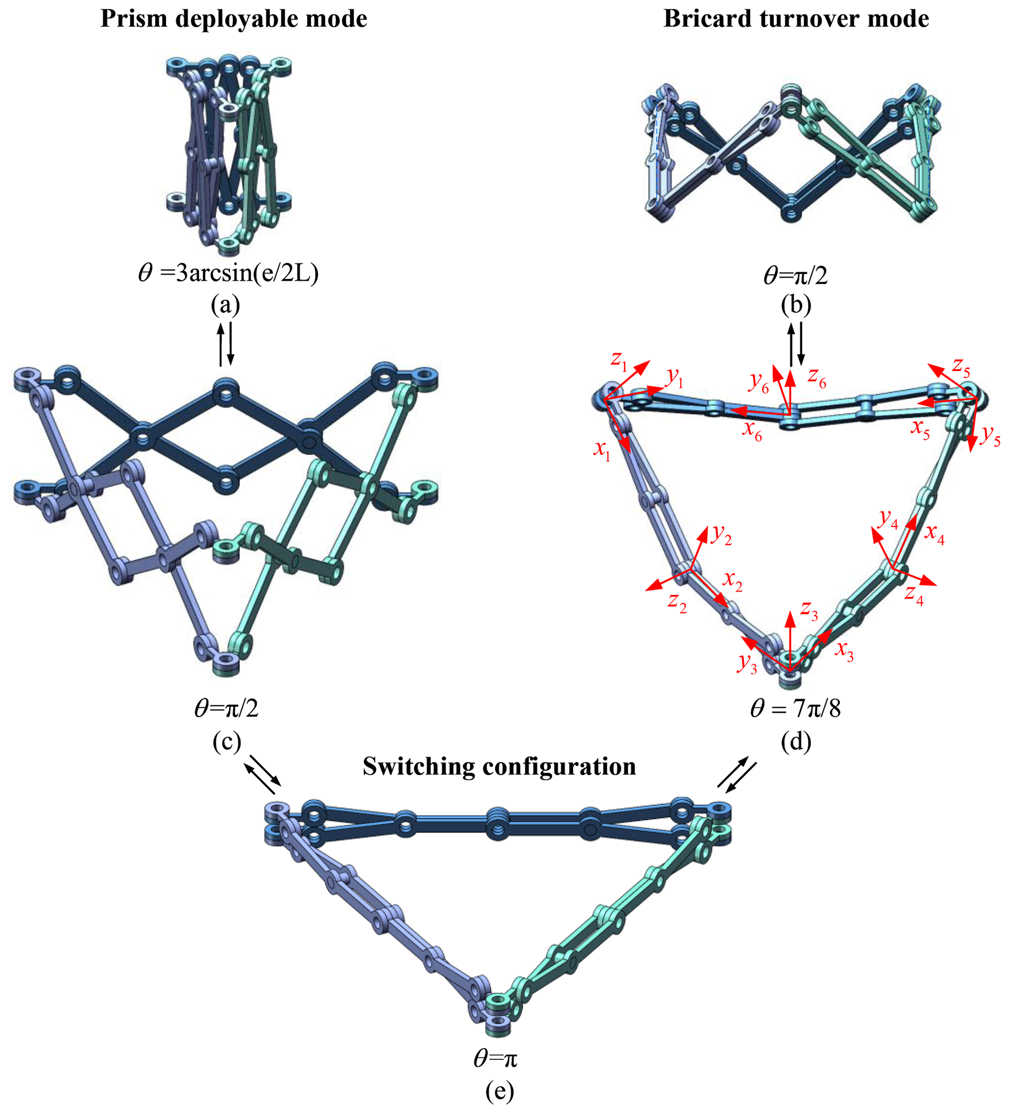
The 3D model of the Bricard-like mechanism is shown in Fig. 2. There are two modes for the reconfigurable deployable mechanism including prism deployable mode and Bricard turnover mode. In the prism deployable mode, it can deploy from a bundle shape to a regular triangle loop on a plane. Then it goes into the switching configuration, in which both the prism deployable motion and the Bricard turnover motion can be realized. When three dual-AE units turn into the rotation mode by fixing six AEs each as a rigid link, the mechanism switches to the Bricard turnover mode which can perform the same infinite turning motion as a TFS Bricard linkage. To analyze the parameters of the model, the standard model proposed by Denavit and Hartenberg (2021) is used.
As shown in Fig. 2d, the coordinate systems of links of the Bricard linkage are established, where zi is the axis along the revolute axis of joint i, and xi is the axis along the common normal direction from axes zi to zi+1. When nodes A and B coincide with each other, each AE with a link of the RRR chain is fixed as a rigid link, and the six rigid links are connected by six R joints to form a TFS Bricard linkage. The geometric parameters of the Bricard linkage contained in the Bricard-like mechanism satisfy the conditions in Eqs. (4)–(7). And referring to Chen et al. (2005), its closure equations are derived in Eq. (8). Then the relationship curve between θ and φ of the Bricard-like mechanism in the Bricard turnover mode is depicted in Fig. 3.
2.2 Construction of the multimode arch
By connecting a number of identical Bricard-like mechanism units in the switching configuration, a multimode deployable arch is constructed. The serial number of the Bricard-like mechanism unit is denoted by (n), as shown in Fig. 4. In order to ensure the symmetry of the mechanism, it is suggested that n is an odd number. From the top view of the multimode arch, the revolute joints of the ith Bricard-like mechanism are denoted by J(2i−1), J(2i), J(2i+1), J(2i+2), J(2i+3), and ; the revolute axes J(2i−1), J(2i+1), and J(2i+3) are directly out of the paper, while J(2i), J(2i+2), and are parallel to the paper. Therefore, these revolute axes are simplified in Fig. 4, where a dot in a circle represents the direction of the axis pointing out of the paper, and where the dotted line represents the direction of the axis paralleling the paper.
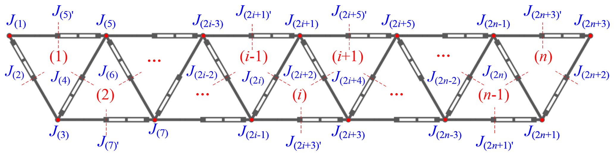
Since the Bricard-like mechanism has 1 degree of freedom (refer to Chen et al. 2005), three identical dual AEs move synchronously. The multimode deployable arch is composed of a number of identical Bricard-like mechanisms, and adjacent Bricard-like mechanisms share their intermediate dual AEs; all of the Bricard-like mechanisms in the arch move synchronously with the first Bricard-like mechanism. Therefore, the multimode deployable arch has 1 degree of freedom as well.
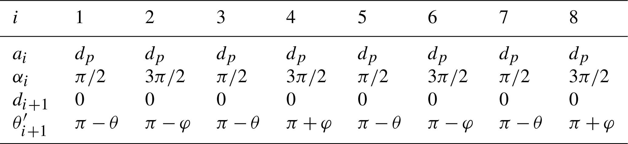
As shown in Fig. 5, the coordinate systems of units (1)–(3) of the deployable arch are established, where zi is the axis along the revolute axis of joint i, and xi is the axis along the common normal direction from axes zi to zi+1. Since the multimode deployable arch is composed of a number of identical Bricard-like mechanisms and they are symmetrically arranged as in Fig. 4, the D–H parameters of the entire arch can be determined by the D–H parameters in Appendix B. As shown in Fig. 8, according to the properties of the three-symmetric Bricard mechanism, the vectors S1, S2, and S3 are guaranteed to intersect at a point, which is named O. Additionally, since S2 is the vector sum of S1 and S3 and since S4 is the vector sum of S3 and S5, then S2 and S4 will necessarily intersect at point O. Moreover, due to the non-collinearity of P2, P4, and O, they lie in the same plane. As shown in Fig. 5, the arch is constructed using identical Bricard-like mechanisms, and adjacent Bricard-like mechanisms share AEs. As a result, S4 and S6 also intersect at point O. Therefore, all the triangular envelope surfaces formed by the Bricard-like mechanisms in the arch are coplanar and intersect at point O.
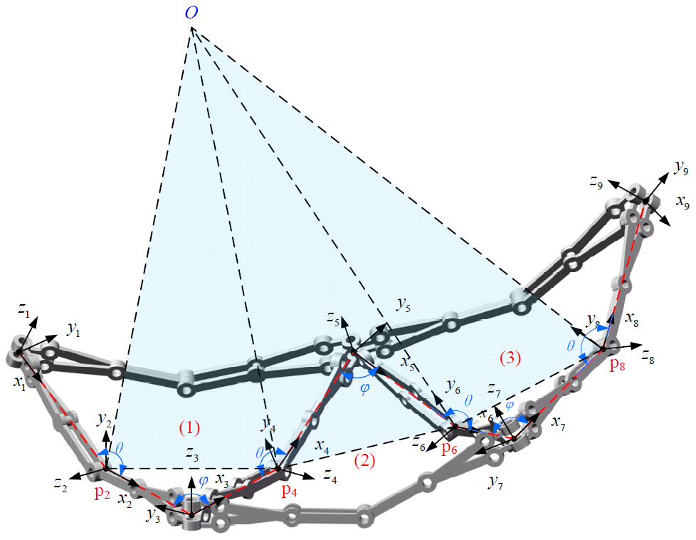
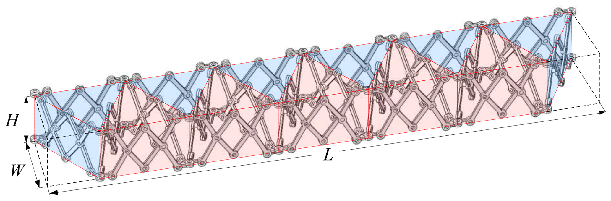
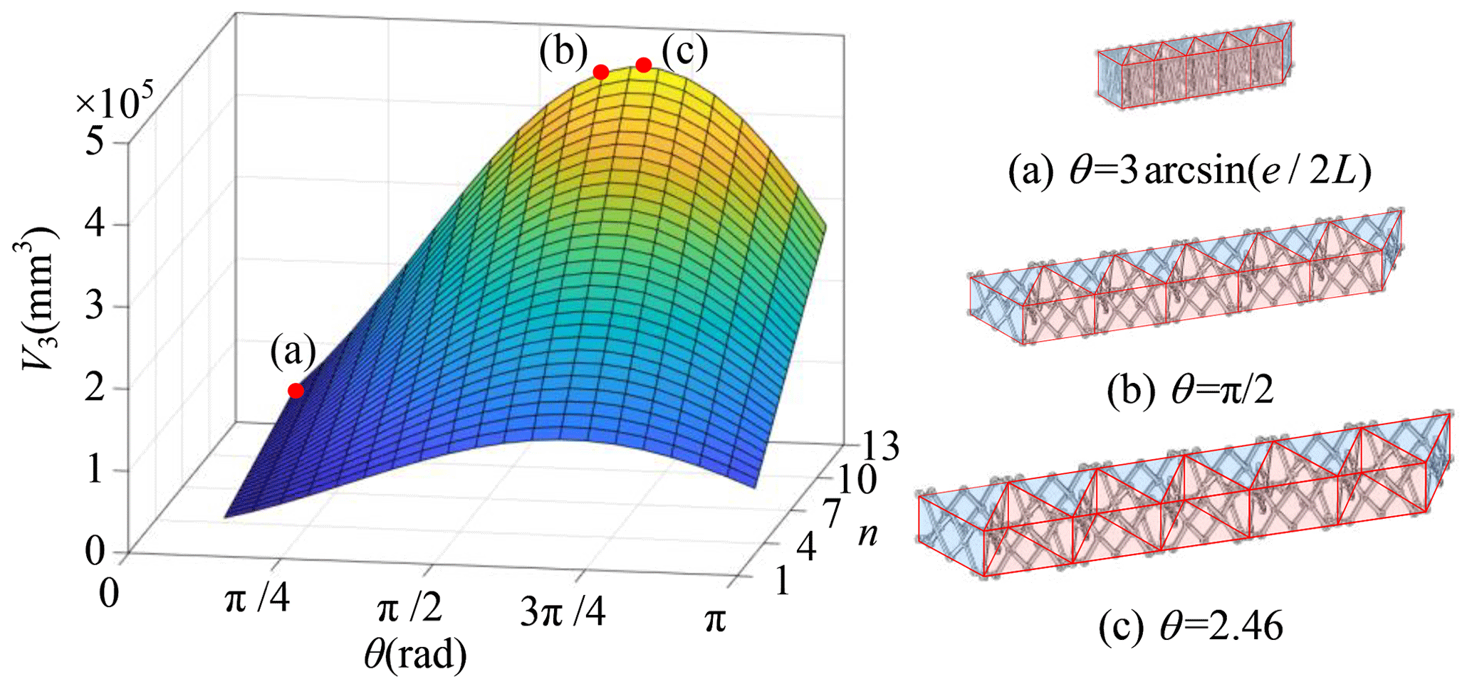
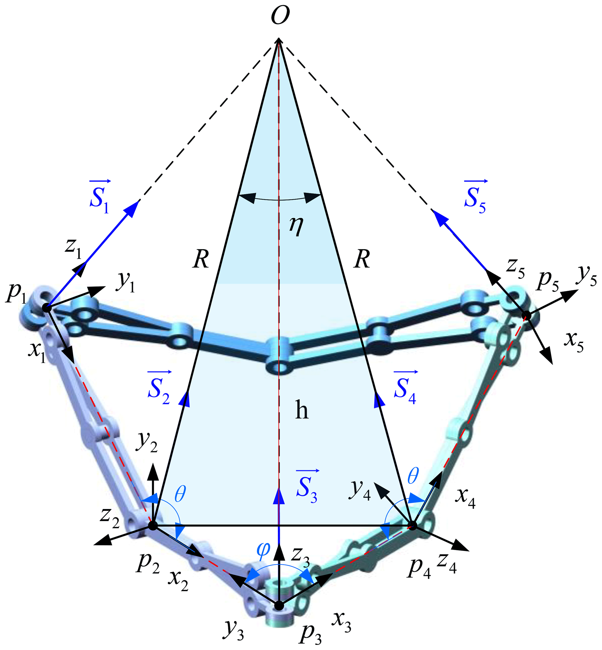
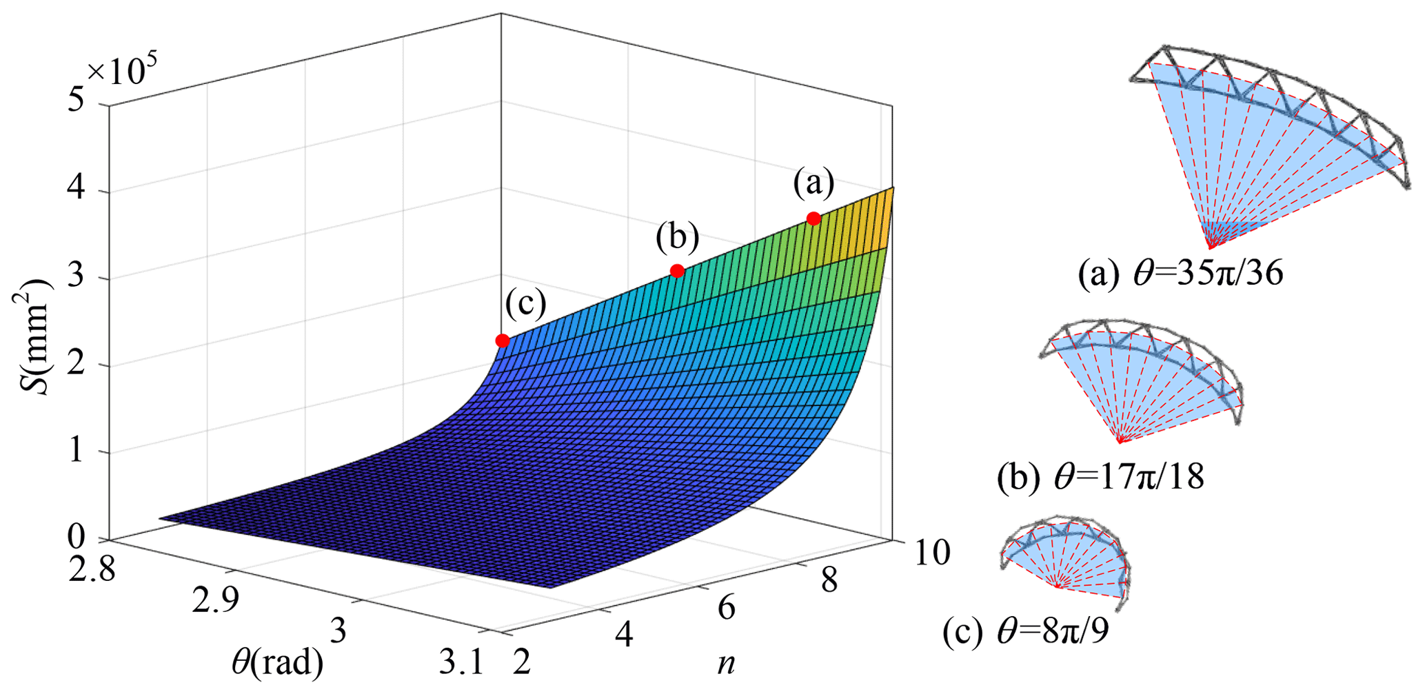
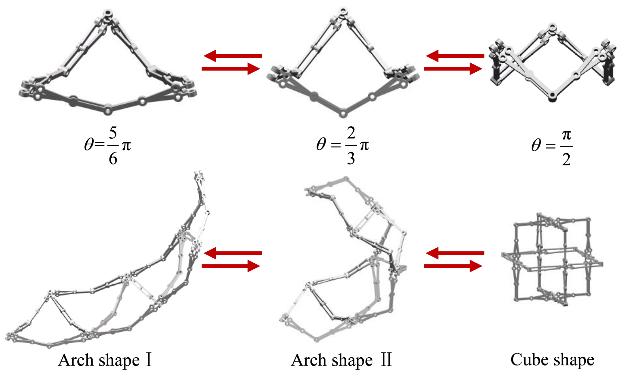
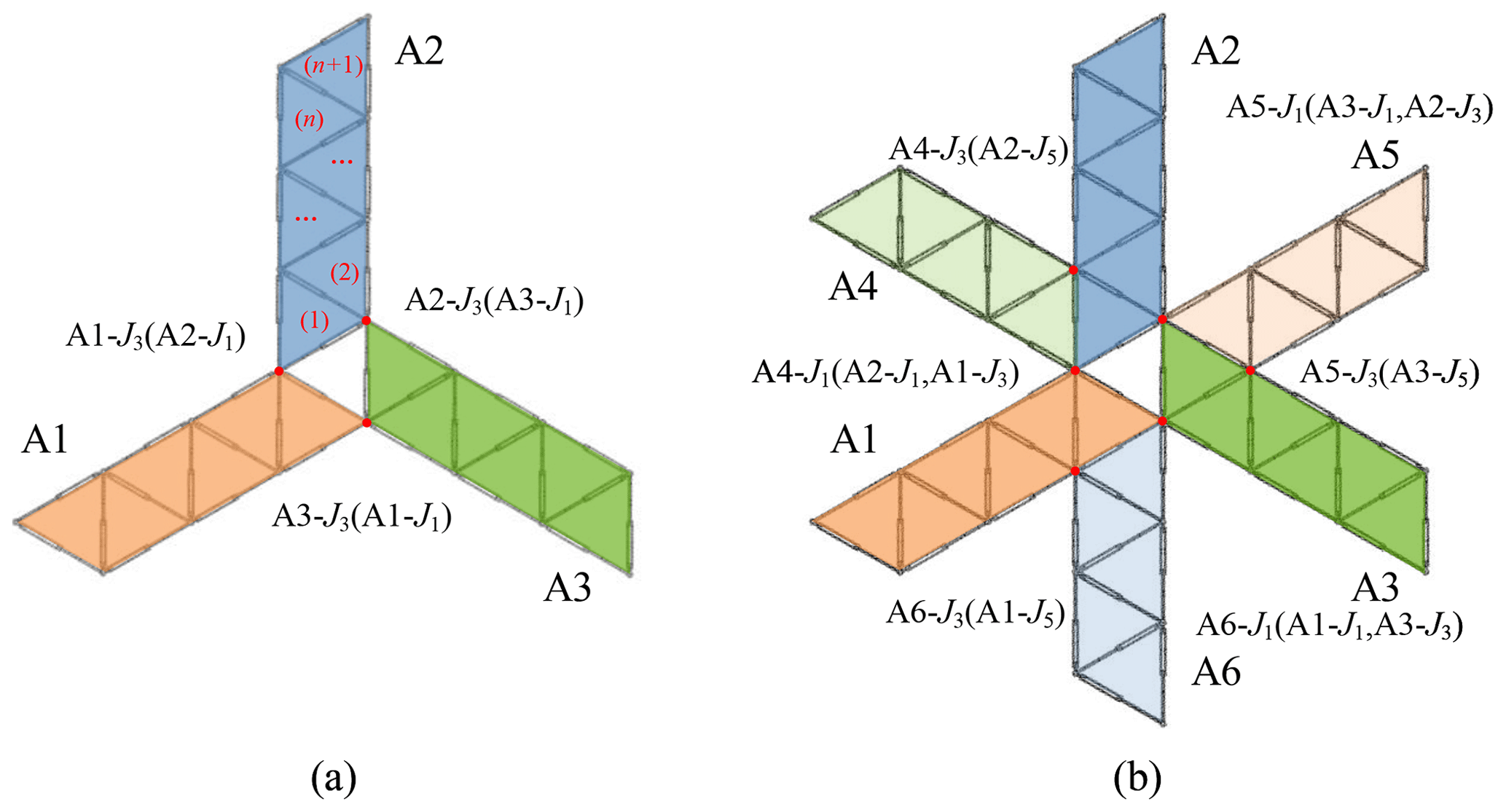
Figure 11Top view of the mechanical network constructed of arches: (a) multimode three-branch center-driven mechanism and (b) multimode six-branch center-driven mechanism.
2.3 Scissor-like deployable mode
In the scissor-like deployable mode, φ remains still at 60∘; the mechanism will fold and deploy as the value of θ varies. To avoid link interference, the range of θ in the scissor-like deployable mode is [, π). Here, we use the length L, the width W, and the height H of the enveloping cuboid to represent the size of the mechanism in the scissor-like deployable mode; here we take 11 Bricard-like units as an example as shown in Fig. 6, and they are derived as follows.
The volume Vs of the enveloping cuboid of the mechanism in scissor-like deployable mode is derived in Eq. (12). The lengths of links L, l, and e can be given different values. Suppose L = 15 mm, l = 6 mm, and e = 4 mm, then the mesh grids of Vs with respect to θ and n is drawn in Fig. 7.
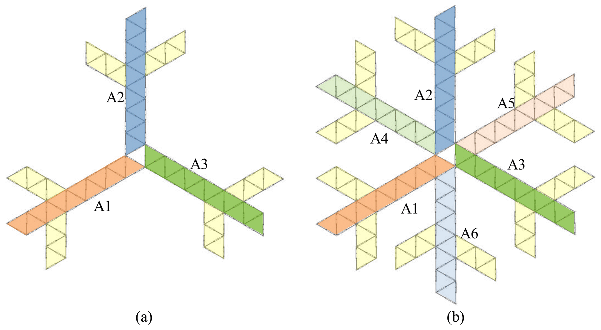
Figure 12Top view of the mechanical network constructed of arches: (a) multimode three-branch center-driven mechanism with extended arches and (b) multimode six-branch center-driven mechanism with extended arches.
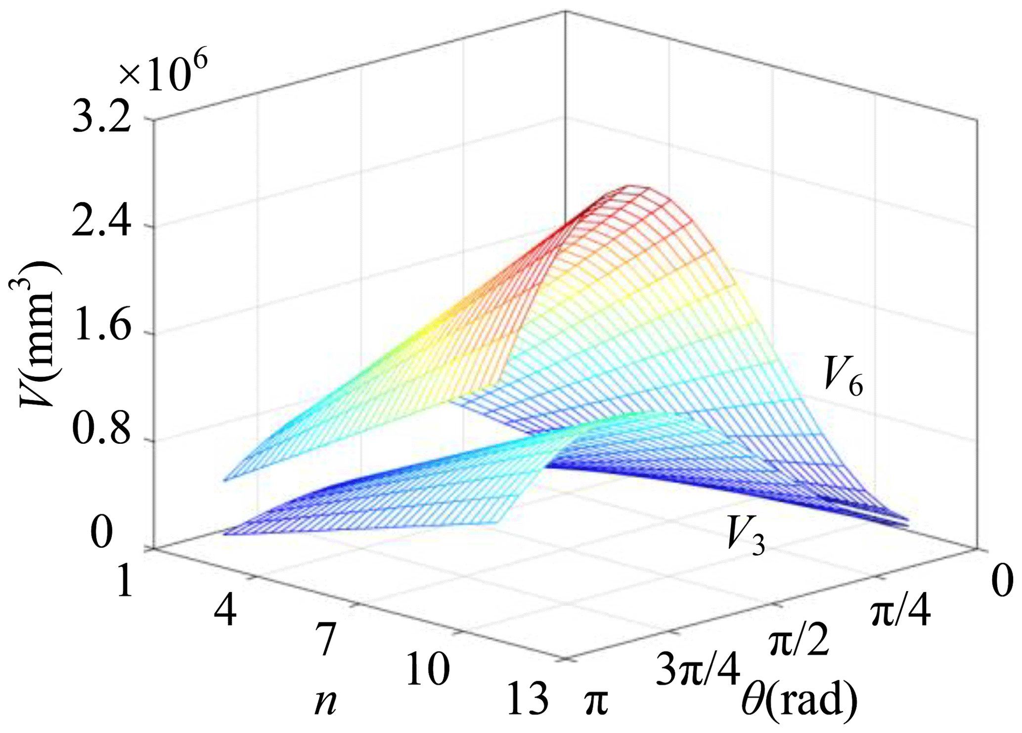
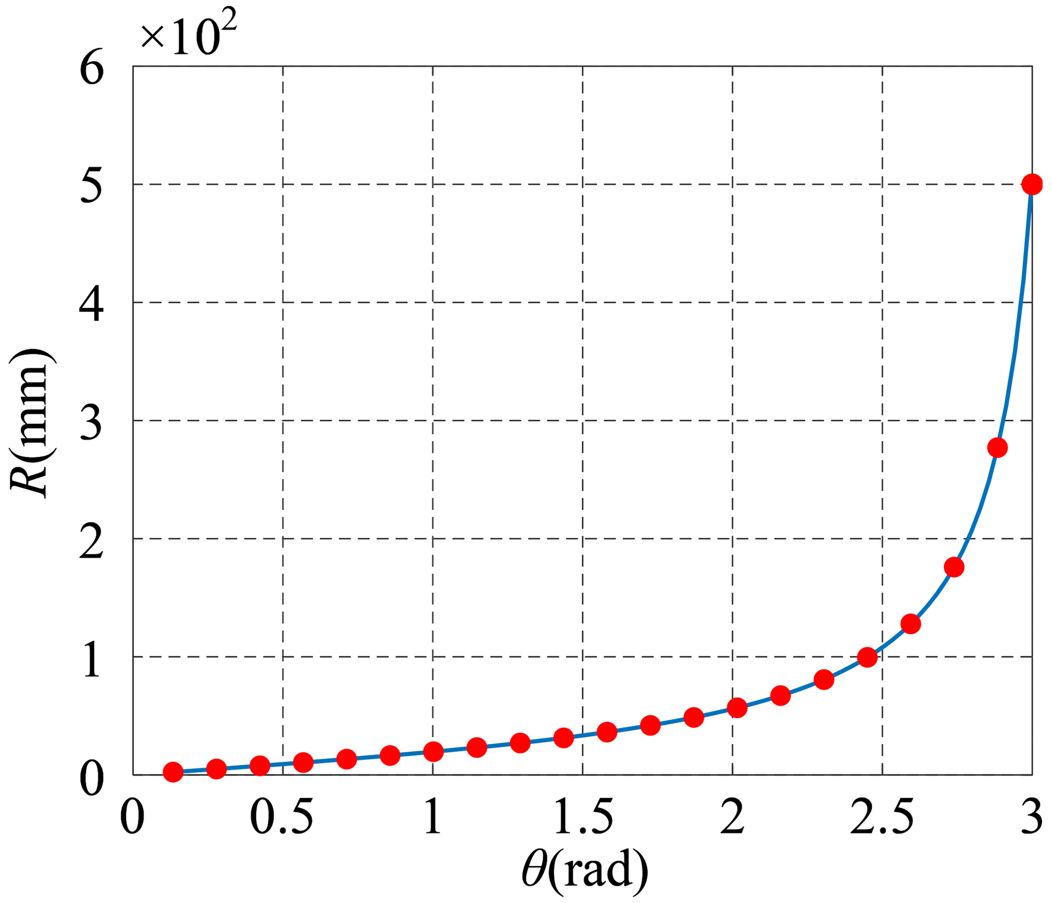
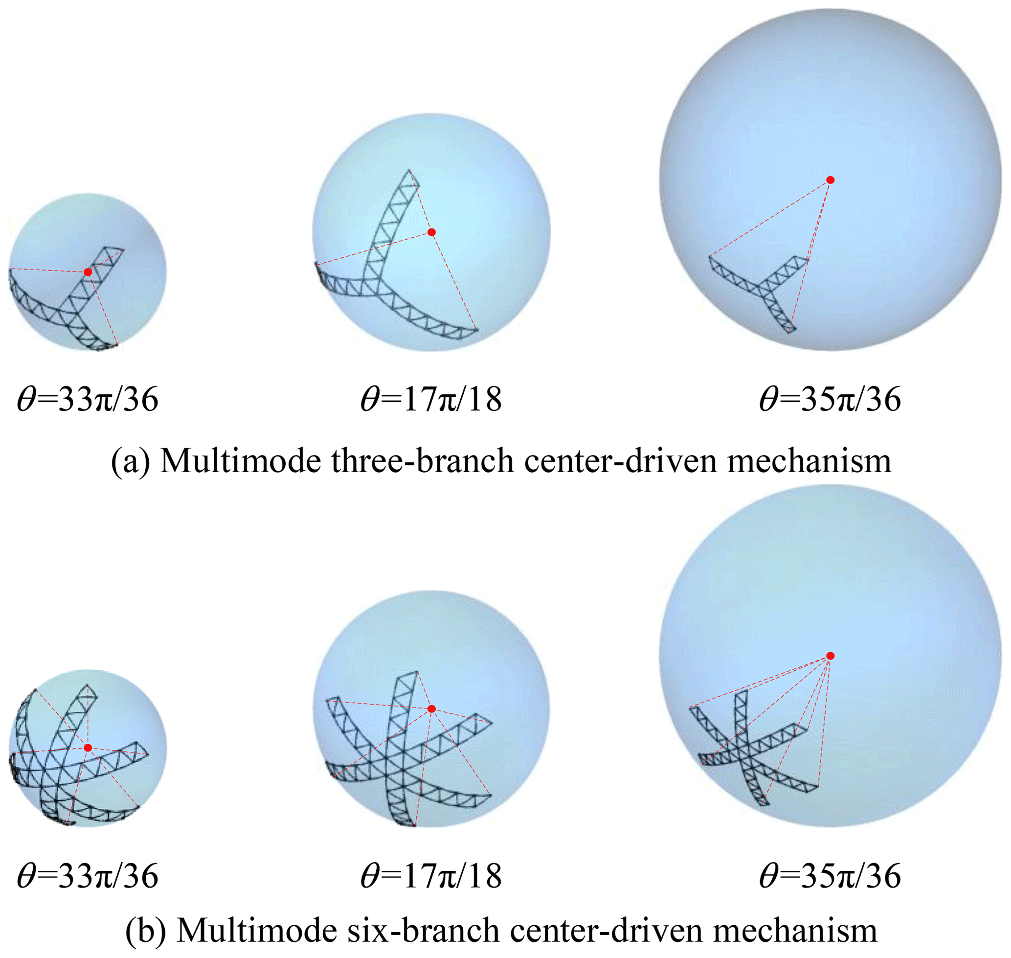
Figure 15The three special states of the mechanism in spherical deformable mode: (a) multimode three-branch center-driven mechanism and (b) multimode six-branch center-driven mechanism
2.4 Arch deformable mode
In arch deformable mode, the Bricard-like mechanism is in turnover mode; each dual AE mechanism with a link of the RRR chain is fixed as a rigid link with the link length of dp, and the six rigid links are connected by six R joints to form a TFS Bricard linkage, as shown in Fig. 8. Then, an area of the sector-like figure enclosed by an arch is derived, as shown in Fig. 5.
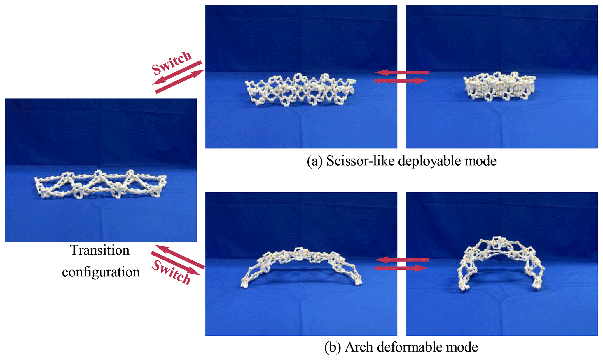
Figure 16Prototype of a multimode arch: (a) scissor-like deployable mode and (b) arch deformable mode.
Table 1Parameters of the multimode arch and multimode center-driven mechanism.
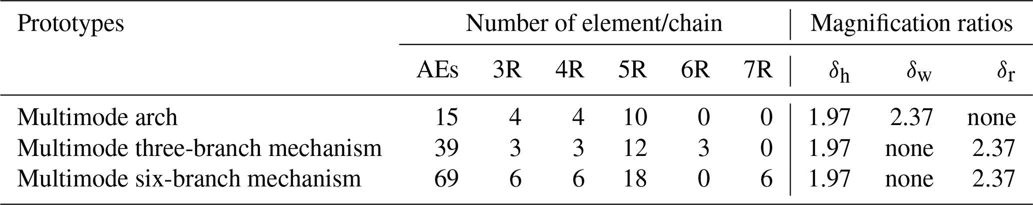
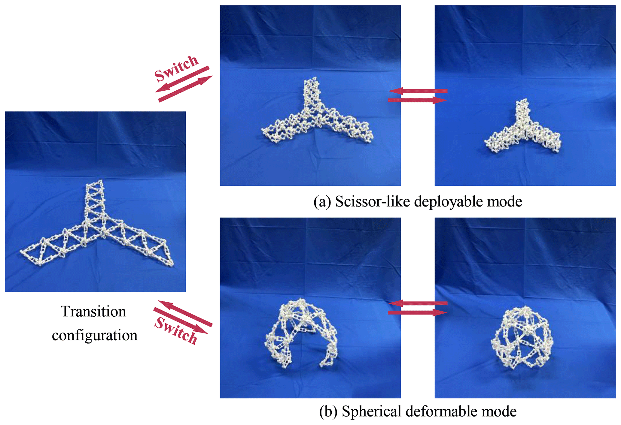
Figure 17Prototype of multimode three-branch center-driven mechanism: (a) scissor-like deployable mode and (b) spherical deformable mode.
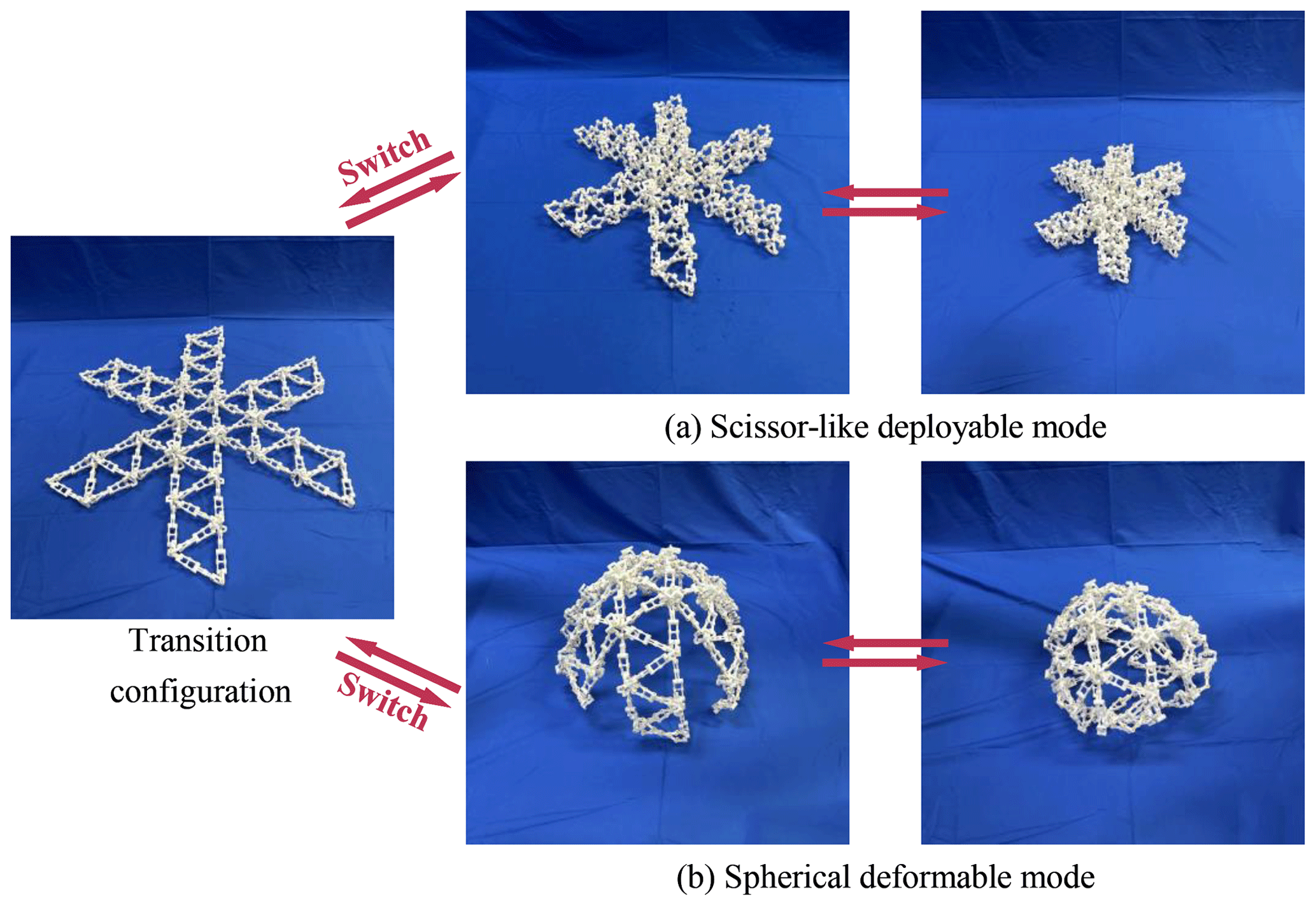
Figure 18Prototype of multimode six-branch center-driven mechanism: (a) scissor-like deployable mode and (b) spherical deformable mode.
The origin of the coordinate system is denoted by Pi (i = 1, 2, …, 2n+3); the sector along Zi (i = 1, 3, 5, …, 2n+3) is denoted by Si. The following is an example of the first Bricard-like mechanism to show the process of calculating the area of the sector-like figure enclosed by an arch. After the first coordinate transformation, the position matrix of S2 can be obtained; then after the second coordinate transformation, the position matrix of S3 can be obtained. The direction of S2 can be obtained by adding S1 and S3. Similarly, the position and direction of S4 can be obtained, as shown in Eqs. (13)–(14).
The intersection point of S2 and S4 is denoted by O, and the angle between S2 and S4 is denoted by η; then an isosceles triangle P2OP4 can be obtained, and the area of the triangle P2OP4 can be obtained.
Since the deployable arch is composed of a number of identical Bricard-like mechanisms in turnover mode, and since the Bricard-like mechanism is symmetrically distributed, the area of the sector-like figure enclosed by the arch is denoted by S and can be obtained from Eqs. (13)–(19).
The lengths of links L, l, and e can be given different values. Suppose L = 15 mm, l = 6 mm, and e = 4 mm, then the mesh grids of S with respect to θ and n are drawn in Fig. 9.
As shown in Fig. 10, the Bricard-like mechanisms of the arch are changed with the angle of θ, and the shape of the arch is changed accordingly; that is, when the angle of θ of the Bricard-like mechanisms become larger, the Bricard-like mechanisms in the arch will become closer. When the number of Bricard-like mechanisms is greater than or equal to 6, the special configuration (cube shape) appears at . Besides, it is easy to see that the arch radius R is equal to the link length dp.
3.1 Construction of multimode center-driven deployable mechanism
The multimode deployable arch discussed above can also be used as a construction unit to construct a center-driven multimode deployable mechanism. As shown in Fig. 11a, the arches are denoted by Aj (j = 1, 2, 3), and the joints in each arch can be denoted as Aj–Ji (i = 1, 2, etc.); by connecting revolute joints A1–J3 and A2–J1, A2–J3 and A3–J1, A3–J1 and A1–J1 separately, a new multimode deployable mechanism is obtained. Since the whole mechanism is composed of three identical arches, a TFS Bricard-like mechanism is constructed among these three arches. As a result, there are 3n+1 Bricard-like mechanisms connected with each other. When one of the Bricard-like mechanisms moves, the whole mechanism will move synchronously with this Bricard-like mechanism; in other words, the center-driven multimode deployable mechanism is a 1 degree-of-freedom mechanism.
Based on the above three-branch center-driven multimode deployable mechanism, revolute joint A4–J1 is added to A1–J3(A2–J1), and A4–J3 is added to A2–J5. Similarly, with the construction approach above, A5–J1 is added to A3–J1(A2–J3), A5–J3 is added to A3–J5, A6–J1 is added to A1–J1(A3–J3), and A6–J3 is added to A1–J5; thus, a six-branch central-driven multimode deployable mechanism is constructed. The specific construction method is shown in Fig. 11b.
Since the six-branch mechanism is composed on the basis of the three-branch mechanism, the three added arches and three-branch mechanism both share the common angulated elements, and the motion of each dual AE of the three-branch mechanism is synchronized, the six-branch mechanism and the three-branch mechanism both move synchronously; that is, the six-branch mechanism has 1 degree of freedom as well. In addition, we can change the size of the mechanism by increasing or decreasing the number of the Bricard-like mechanisms in each arch.
Furthermore, as shown in Fig. 12, on the basis of the multimode center-driven deployable mechanisms, new mechanisms can be obtained by adding shorter arches at different positions of the multimode center-driven deployable mechanisms. The newly obtained mechanisms still have two motion modes, namely, scissor-like deployable mode and spherical deformable mode, which can be switched through the transition configuration. Furthermore, since the newly added arches still share the common AEs, i.e., all the AEs of the whole mechanism still move synchronously, as a result, the multimode center-driven deployable mechanisms with arches still have only 1 degree of freedom, and the stiffness of the whole mechanism has been improved. However, in the case that the interference of the links is considered, the more arches added, the smaller deformation range of the mechanism under the spherical transformation mode.
3.2 Scissor-like deployable mode
In the scissor-like deployable mode, φ remains still at 60∘; the spherical mechanism will fold and deploy as the value of θ varies like the arch. To avoid link interference, the range of θ in the scissor-like deployable mode is [, π) as well. Here, we use V3 and V6 of the enveloping cuboid to represent the size of the mechanism in the scissor-like deployable mode, respectively; the lengths of links L, l, and e can be given different values. Suppose L = 15 mm, l = 6 mm, and e = 4 mm, then the mesh grids of V3 and V6 with respect to θ and n are drawn in Fig. 13.
3.3 Spherical deformable mode
When the arch is in arch deformable mode, the length from the position of each revolute joint to the vertex of the sector-like figure is equal, and the multimode center-driven deployable mechanism is constructed by connecting three identical arches. The multimode center-driven deployable mechanism will envelop a spherical mechanism, the radius of the enveloping sphere will change as the value of θ varies, and the multimode center-driven deployable mechanism is in spherical deformable mode. We use the radius R of the enveloping sphere to represent the size of the mechanism, and it is calculated in Eq. (20), the lengths of links L, l, and e can be given different values. Suppose L = 15 mm, l = 6 mm, and e = 4 mm, then the relationship curve between θ and R of the spherical mechanism in the spherical deformable mode is described in Fig. 14. In addition, when , , and , the states of the mechanism in spherical deformable mode are shown in Fig. 15.
Based on the Bricard-like mechanism, the prototype of a multimode arch is fabricated, as shown in Fig. 16. The link length L and the node diameter e of the AE are 20 and 10 mm. The link length of the 3R, 4R, and 5R chain l is 20 mm, and parameters of the multimode arch are listed in Table 1.
In the scissor-like deployable mode, as shown in Fig. 16a, the variable ranges of width and the height of the enveloping cuboid of the mechanism are [43.30 mm, 102.81 mm] and [20.00 mm, 39.36 mm], respectively. And the magnification ratios of the arch are δh = 1.97 and δw = 2.37. In the deformable mode, as shown in Fig. 16b, each Bricard-like unit of the arch is in turnover mode, and the rigid link length of the Bricard-like mechanism is 59.36 mm.
The three multimode arches are assembled, and a prototype of a multimode center-driven mechanism is fabricated, as shown in Fig. 17. The parameters of the multimode center-driven mechanism are also listed in Table 1. In scissor-like deployable mode, the variable ranges of radius and the height of the enveloping cuboid of the mechanism are [176.33 mm, 418.69 mm] and [20.00 mm, 39.36 mm], respectively. And the magnification ratios of the arch are δh = 1.97 and δr = 2.37. In spherical deformable mode, the variable range of radius of the enveloping sphere of the mechanism is [306.81 mm, 880.68 mm] when θ is in the range [, ].
Figure 18 shows the prototype of the multimode six-branch center-driven mechanism. And the parameters of the mechanism are also listed in Table 1. In scissor-like deployable mode, the variable ranges of radius and the height of the enveloping cuboid of the mechanism are [176.33 mm, 418.69 mm] and [20.00 mm, 39.36 mm], respectively. And the magnification ratios of the arch are δh = 1.97 and δr = 2.37. In spherical deformable mode, the variable range of radius of the enveloping sphere of the mechanism is [306.81 mm, 880.68 mm] when θ is in the range [, ].
A family of multimode deployable mechanisms based on a TFS Bricard-like mechanism is proposed. An arch is designed by connecting a number of identical Bricard-like mechanisms, and two adjacent units share their intermediate links. The obtained arch can switch between the scissor-like deployable mode and the arch deformable mode through the transition configuration. Variable ranges on the length, width, height, and volume of the enveloping cuboid of the mechanism in the scissor-like deployable mode are calculated. Besides, the position and orientation of the revolute joints of the mechanism are analyzed. And the radius and area of the sector-like figure enclosed by an arch are derived.
Further, the presented arch can be used as a unit to construct multimode center-driven deployable mechanisms; the volume of the enveloping cuboid of the mechanisms in the scissor-like deployable mode is calculated, and the radius of the mechanism in spherical deformable mode is derived. A physical prototype of the multimode deployable arch is fabricated, and two prototypes of multimode center-driven deployable mechanisms are manufactured and tested. Therefore, the obtained multimode deployable mechanism can be reassembled into a new size by adjusting the number of Bricard-like mechanisms. The proposed mechanisms enriched the reconfigurable deployable mechanisms, and they can be used in deployable antennas in the future to increase their function and adaptability. Considering the property of folding performance and reassembly feasibility of the multimode arch, referring to Song et al. (2021), the multi-layer deployable mechanism will be constructed in the next work.
The closure equation of the spatial single-loop over-constrained 6R mechanism is as follows:
where is the transformation matrix from joint i to joint i+1; when i=6, ; I is the identity matrix. The transformation matrix is as follows.
The coordinate systems of two adjacent links connected by revolute joints are shown in Fig. A1: the line along the revolute axis of joint i is set as the coordinate axis zi; the line along the common normal between joint axes zi and zi+1 is set as the coordinate axis xi. The D–H parameters are defined as follows: ai is the length of link i(i+1), which is the common normal distance from zi to zi+1 positively along the direction of xi; αi is the twist of link i(i+1), which is the rotation angle from zi to zi+1 positively along the direction of xi; di+1 is the offset of joint i, which is the common normal from xi to xi+1 positively along the direction of zi+1; is the revolute variable of joint i, which is the rotation angle from xi to xi+1 positively along the direction zi+1.
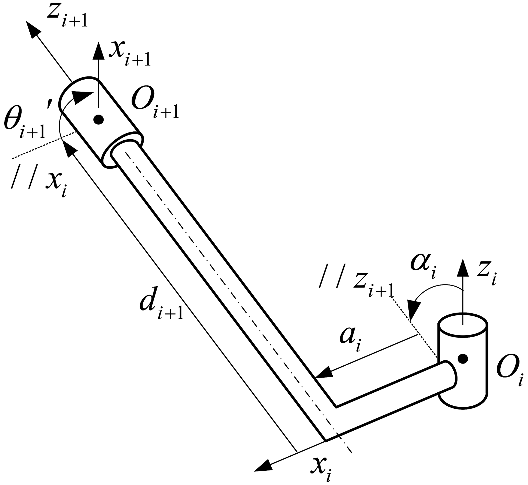
Table B1The D–H parameters of units (1)–(3) of the deployable arch.
All data included in this study are available upon request to the corresponding author.
The supplement related to this article is available online at: https://doi.org/10.5194/ms-14-387-2023-supplement.
RuL and XZ proposed the idea of the multimode deployable mechanism and developed the structure scheme. XZ prepared the figures and wrote this paper. RuL, SZ, RaL, and YY edited the paper.
The contact author has declared that none of the authors has any competing interests.
Publisher’s note: Copernicus Publications remains neutral with regard to jurisdictional claims in published maps and institutional affiliations.
The authors would like to thank the reviewers for their valuable comments and suggestions that enabled us to revise the paper.
This research has been supported by the Fundamental Research Funds for the Central Universities (grant no. 2021RC252) and National Natural Science Foundation of China (grant no. 51905015).
This paper was edited by Daniel Condurache and reviewed by three anonymous referees.
Bai, G., Liao, Q., Li, D., and Wei, S.: Synthesis of scaling mechanisms for geometric figures with angulated-straight elements, P. I. Mech. Eng. C-J. Mec., 227, 2795–2809, https://doi.org/10.1177/0954406213478280, 2013.
Bennett, G. T.: A new mechanism, Engineering, 76, 777–778, 1903.
Bennett, G. T.: The Skew Isogram Mechanism, P. Lond. Math. Soc., s2-13, 151–173, https://doi.org/10.1112/plms/s2-13.1.151, 1914.
Bricard, R.: Mémoire sur la théorie de l'octaèdre articulé, J. Math. Pure. Appl., 3, 113–148, 1897.
Bricard, R.: Leçons de cinématique, Gauthier-Villars, 358 pp., 1926.
Cao, W., Jing, Z., and Ding, H.: A general method for kinematics analysis of two-layer and two-loop deployable linkages with coupling chains, Mech. Mach. Theory, 152, 103945, https://doi.org/10.1016/j.mechmachtheory.2020.103945, 2020.
Cao, W., Xi, S., Ding, H., and Chen, Z.: Design and Kinematics of a Novel Double-Ring Truss Deployable Antenna Mechanism, J. Mech. Design, 143, 124502, https://doi.org/10.1115/1.4051352, 2021.
Chen, Y. and You, Z.: An Extended Myard Linkage and its Derived 6R Linkage, J. Mech. Design, 130, 052301, https://doi.org/10.1115/1.2885506, 2008a.
Chen, Y. and You, Z.: On mobile assemblies of Bennett linkages, P. Roy. Soc. A-Math. Phy., 464, 1275–1293, https://doi.org/10.1098/rspa.2007.0188, 2008b.
Chen, Y., You, Z., and Tarnai, T.: Threefold-symmetric Bricard linkages for deployable structures, Int. J. Solids Struct., 42, 2287–2301, https://doi.org/10.1016/j.ijsolstr.2004.09.014, 2005.
Cheng, P., Ding, H., Cao, W., Gosselin, C., and Geng, M.: A novel family of umbrella-shaped deployable mechanisms constructed by multi-layer and multi-loop spatial linkage units, Mech. Mach. Theory, 161, 104169, https://doi.org/10.1016/j.mechmachtheory.2020.104169, 2021.
Dai, J. S. and Rees Jones, J.: Mobility in Metamorphic Mechanisms of Foldable/Erectable Kinds, J. Mech. Design, 121, 375–382, https://doi.org/10.1115/1.2829470, 1999.
Denavit, J. and Hartenberg, R. S.: A Kinematic Notation for Lower-Pair Mechanisms Based on Matrices, J. Appl. Mech., 22, 215–221, https://doi.org/10.1115/1.4011045, 2021.
Deng, Z., Huang, H., Li, B., and Liu, R.: Synthesis of Deployable/Foldable Single Loop Mechanisms With Revolute Joints, J. Mech. Robot., 3, 031006, https://doi.org/10.1115/1.4004029, 2011.
Ding, X., Yang, Y., and Dai, J. S.: Design and kinematic analysis of a novel prism deployable mechanism, Mech. Mach. Theory, 63, 35–49, https://doi.org/10.1016/j.mechmachtheory.2013.01.001, 2013.
Escrig, F.: Expandable Space Structures, International Journal of Space Structures, 1, 79–91, https://doi.org/10.1177/026635118500100203, 1985.
Goldberg, M.: New Five-Bar and Six-Bar Linkages in Three Dimensions, T. ASME, 65, 649–661, 1943.
Guo, J., Zhao, Y., Xu, Y., and Zhang, G.: Mechanics analysis and structural design of a truss deployable antenna mechanism based on 3RR-3URU tetrahedral unit, Mech. Mach. Theory, 171, 104749, https://doi.org/10.1016/j.mechmachtheory.2022.104749, 2022.
Hoberman, C.: (54) GEARED EXPANDING STRUCTURES, Patent 7464503B2, USA, 2008.
Huang, H., Li, B., Zhang, T., Zhang, Z., Qi, X., and Hu, Y.: Design of Large Single-Mobility Surface-Deployable Mechanism Using Irregularly Shaped Triangular Prismoid Modules, J. Mech. Design, 141, 012301, https://doi.org/10.1115/1.4041178, 2019.
Kiper, G., Söylemez, E., and Kişisel, A. U. Ö.: A family of deployable polygons and polyhedra, Mech. Mach. Theory, 43, 627–640, https://doi.org/10.1016/j.mechmachtheory.2007.04.011, 2008.
Kong, X.: Type Synthesis of 3-DOF Parallel Manipulators With Both a Planar Operation Mode and a Spatial Translational Operation Mode1, J. Mech. Robot., 5, 041015, https://doi.org/10.1115/1.4025219, 2013.
Li, D., Zhang, Z., and McCarthy, J. M.: A constraint graph representation of metamorphic linkages, Mech. Mach. Theory, 46, 228–238, https://doi.org/10.1016/j.mechmachtheory.2010.09.003, 2011.
Li, R., Yao, Y., and Kong, X.: A class of reconfigurable deployable platonic mechanisms, Mech. Mach. Theory, 105, 409–427, https://doi.org/10.1016/j.mechmachtheory.2016.07.019, 2016.
Li, R., Yao, Y., and Kong, X.: Reconfigurable deployable polyhedral mechanism based on extended parallelogram mechanism, Mech. Mach. Theory, 116, 467–480, https://doi.org/10.1016/j.mechmachtheory.2017.06.014, 2017.
Li, R., Yao, Y., and Ding, X.: A family of reconfigurable deployable polyhedral mechanisms based on semiregular and Johnson polyhedra, Mech. Mach. Theory, 126, 344–358, https://doi.org/10.1016/j.mechmachtheory.2018.04.021, 2018.
Li, R., Sun, X., Chen, Y., Yao, Y., and Ding, X.: Design and Analysis of Reconfigurable Deployable Polyhedral Mechanisms With Straight Elements, J. Mech. Robot., 11, 044502, https://doi.org/10.1115/1.4043601, 2019.
Liu, R., Li, R., and Yao, Y.-A.: Reconfigurable deployable Bricard-like mechanism with angulated elements, Mech. Mach. Theory, 152, 103917, https://doi.org/10.1016/j.mechmachtheory.2020.103917, 2020.
Lu, S., Zlatanov, D., Ding, X., Zoppi, M., and Guest, S. D.: A Network of Type III Bricard Linkages, J. Mech. Robot., 11, 011013, https://doi.org/10.1115/1.4041641, 2019.
Lu, S., Zlatanov, D., Zoppi, M., Ding, X., Chirikjian, G. S., and Guest, S. D.: Bundle folding type III Bricard linkages, Mech. Mach. Theory, 144, 103663, https://doi.org/10.1016/j.mechmachtheory.2019.103663, 2020.
Ma, X., Zhang, K., and Dai, J. S.: Novel spherical-planar and Bennett-spherical 6R metamorphic linkages with reconfigurable motion branches, Mech. Mach. Theory, 128, 628–647, https://doi.org/10.1016/j.mechmachtheory.2018.05.001, 2018.
Myard, F. E.: Contribution à la géométrie des systèmes articulés, B. Soc. Math. Fr., 59, 183–210, https://doi.org/10.24033/bsmf.1179, 1931.
Puig, L., Barton, A., and Rando, N.: A review on large deployable structures for astrophysics missions, Acta Astronaut., 67, 12–26, https://doi.org/10.1016/j.actaastro.2010.02.021, 2010.
Qi, X., Huang, H., Miao, Z., Li, B., and Deng, Z.: Design and Mobility Analysis of Large Deployable Mechanisms Based on Plane-Symmetric Bricard Linkage, J. Mech. Design, 139, 022302, https://doi.org/10.1115/1.4035003, 2017.
Song, C. Y. and Chen, Y.: A family of mixed double-Goldberg 6R linkages, P. Roy. Soc. A-Math. Phy., 468, 871–890, https://doi.org/10.1098/rspa.2011.0345, 2012.
Song, X., Guo, H., Liu, R., Meng, F., Chen, Q., Xu, Y., and Liu, R.: Mobility Analysis of the Threefold-Symmetric Bricard Linkage and Its Network, J. Mech. Robot., 12, 011013, https://doi.org/10.1115/1.4044415, 2020.
Song, X., Guo, H., Chen, J., Yuan, W., and Xu, Y.: Double-Layer Deployable Mechanical Network Constructed of Threefold-Symmetric Bricard Linkages and Sarrus Linkages, J. Mech. Robot., 13, 061010, https://doi.org/10.1115/1.4050929, 2021.
Sun, X., Li, R., Xun, Z., and Yao, Y.-A.: A new Bricard-like mechanism with anti-parallelogram units, Mech. Mach. Theory, 147, 103753, https://doi.org/10.1016/j.mechmachtheory.2019.103753, 2020a.
Sun, X., Yao, Y.-A., and Li, R.: Novel method of constructing generalized Hoberman sphere mechanisms based on deployment axes, Front. Mech. Eng., 15, 89–99, https://doi.org/10.1007/s11465-019-0567-5, 2020b.
Sun, X., Li, R., Xun, Z., Kong, X., and Yao, Y.-A.: A multiple-mode mechanism composed of four antiparallelogram units and four revolute joints, Mech. Mach. Theory, 155, 104106, https://doi.org/10.1016/j.mechmachtheory.2020.104106, 2021.
Viquerat, A. D., Hutt, T., and Guest, S. D.: A plane symmetric 6R foldable ring, Mech. Mach. Theory, 63, 73–88, https://doi.org/10.1016/j.mechmachtheory.2012.12.004, 2013.
Wang, J. and Kong, X.: Deployable mechanisms constructed by connecting orthogonal Bricard linkages, 8R or 10R single-loop linkages using S joints, Mech. Mach. Theory, 120, 178–191, https://doi.org/10.1016/j.mechmachtheory.2017.09.017, 2018a.
Wang, J. and Kong, X.: Deployable polyhedron mechanisms constructed by connecting spatial single-loop linkages of different types and/or in different sizes using S joints, Mech. Mach. Theory, 124, 211–225, https://doi.org/10.1016/j.mechmachtheory.2018.03.002, 2018b.
Wang, S., Huang, H., Jia, G., Li, B., Guo, H., and Liu, R.: Design of a novel three-limb deployable mechanism with mobility bifurcation, Mech. Mach. Theory, 172, 104789, https://doi.org/10.1016/j.mechmachtheory.2022.104789, 2022.
Wohlhart, K.: Polyhedral Zig-Zag Linkages, in: On Advances in Robot Kinematics, edited by: Lenarčič, J. and Galletti, C., Springer Netherlands, Dordrecht, 351–360, https://doi.org/10.1007/978-1-4020-2249-4_38, 2004.
Yang, F., You, Z., and Chen, Y.: Foldable Hexagonal Structures Based on the Threefold-Symmetric Bricard Linkage, J. Mech. Robot., 11, https://doi.org/10.1115/1.4045039, 2020.
You, Z. and Pellegrino, S.: Foldable bar structures, Int. J. Solids Struct., 34, 1825–1847, https://doi.org/10.1016/S0020-7683(96)00125-4, 1997.
Zhao, J.-S., Chu, F., and Feng, Z.-J.: The mechanism theory and application of deployable structures based on SLE, Mech. Mach. Theory, 44, 324–335, https://doi.org/10.1016/j.mechmachtheory.2008.03.014, 2009.