the Creative Commons Attribution 4.0 License.
the Creative Commons Attribution 4.0 License.
 | 03 Feb 2023
A feasibility and dynamic performance analysis of hydromechanical hybrid power transmission technology for wind turbines
Dharmendra Kumar
A multi-body dynamical model of a wind turbine power generation system (WTPGS) based on hydromechanical hybrid power transmission (HMHPT) technology is developed and simulated to overcome the individual drawbacks of the gear train and hydrostatic power transmission (HPT) system. The HMHPT is a hybrid concept of a single-stage planetary gear train (SSPGT) and a typical HPT. The input shaft of the SSPGT is coupled with the turbine rotor, whereas the output shaft of the SSPGT is coupled with the shaft of a hydraulic pump. The hydraulic pump supplies flow to the hydro-motor, and its shaft is coupled with the generator. An existing turbine blade model of 750 kW based wind turbine is used for further development and analysis of the HMHPT. The simulation responses indicate that the power generation and the control potential both have been improved using the HMHPT in a wind turbine. Moreover, the influence on the motor power generation due to variations of pump and motor leakages is addressed. Additionally, it is found that if the order of the SSPGT and the HPT are swapped in the proposed HMHPT, then the settling time, maximum overshoot, and rise time of the system responses are increased. As a result, the controllability of the system is decreased.
- Article
(6246 KB) - Full-text XML
- BibTeX
- EndNote


Wind energy is an eco-friendly renewable source of energy. There is plenty of wind energy available around us but is in an unavailable form of energy. A wind turbine is a device which converts unavailable forms of wind energy into available forms of energy. It utilizes wind power to generate electricity. Naturally, the wind power is highly fluctuating in nature due to frequent changes of weather. Therefore, the power generated from the wind turbine should be stored into a suitable energy storage system (ESS) to reduce energy wastage. Presently, various energy storage techniques are available, such as the pumped-hydroelectric energy storage system (PHEESS), underground PHEESS, compressed air ESS, ESS using battery, hydrogen ESS, and thermal ESS (Mitra et al., 2022). In wind turbines, the most important technical units are the turbine blades model, tower design, power transmission unit, and electric generator. Among all these stated units, the power transmission division is a key unit in wind turbines to transmit power from the turbine rotor to the electric generator. The most frequently used power transmission system in a wind turbine is the gear train (Sanchez and Medina, 2014; Khaouch et al., 2016). However, previously, many researchers tried to utilize a hydrostatic power transmission (HPT) in a wind turbine to provide an alternative transmission unit instead of the gear train (Laguna, 2015; Jiang et al., 2014; D. Kumar et al., 2022). The gear train is installed between the turbine rotor and the generator and helps to magnify the rotational speed of the low-speed rotor to the high-speed electrical generator. It is more efficient than HPT, but the probability of failure is higher (Liu et al., 2015). In addition, the maintenance cost of the gear train is higher, and it may be faded out whenever the power rating is more than 3 MW (Arturo Soriano et al., 2013). However, there is no provision to store the extra energy generated from the wind turbine during cyclones, storms, etc. Therefore, a huge amount of energy is wasted during a storm or cyclone when a gear train is connected in a wind turbine. Besides, in an HPT, a hydraulic pump is coupled with the turbine rotor and an actuator/Pelton wheel is coupled with the electric generator. The electric generator produces electricity. Previously, in wind turbine applications, both closed-loop and open-loop HPTs were successfully applied (Mahato and Ghoshal, 2019; Laguna et al., 2014; Buhagiar et al., 2015). Recently, Fan et al. (2016) and Mahato et al. (2018) used an accumulator in an HPT to minimize the power fluctuation. Here, the accumulator acted as an energy storage device. It stores and releases energy during high and low wind speeds, respectively. It is found that the HPT with an accumulator helps the wind turbine to produce stable power from the generator under fluctuating wind speed (Fan et al., 2016; Mahato et al., 2018). Hence, the stated concepts may reduce the load shedding probability at the wind power supply locations. The major issue associated with HPTs is lower transmission efficiency, which is about 70 % compared to the 90 % transmission efficiency in gear trains (Liu et al., 2011). In addition, the size of the hydraulic pump is influenced by the speed of the rotor. In the literature (Rampen, 2007), a 68-plunger cylinder is used for a 1.5 MW wind turbine generation system. Therefore, the large displacement-based hydraulic pump installment not only increases the cost involvement, but is also difficult to manufacture by manufacturing industries. The stated issues hinder the promotion of HPTs in wind turbine applications (Wang et al., 2011; Liu and Fan, 2011). The discussed drawbacks of the gear train power transmission and HPTs can be overcome by introducing various types of hybrid power transmission technologies (Yin et al., 2014; Jelaska et al., 2015; Yin et al., 2016, 2019). Yin et al. (2014, 2016) presented a continuously variable power transmission based on a hydro-viscous concept for wind turbine application. This technology worked on mature technology, and it is characterized by high reliability and low production cost. Another similar hydro-viscous power transmission system for wind turbines is modeled and analyzed by Jelaska et al. (2015). It used a well-known particle swarm optimization algorithm to obtain the optimal design of hydro-viscous technology. Yin et al. (2019) eliminated the need of a frequency converter by incorporating a single-stage planetary gear train (SSPGT) and a control system in a wind turbine. The control system includes some sensors and a control motor which is controlled by a microprocessor. The stated scheme helps to obtain a fixed power output without altering the blade pitch angle. The commercial feasibility of the hydro-viscous power transmission system for higher power transmission is restricted due to the complex structure. Another hybrid approach, i.e., a gear train combined with an HPT, is discussed in articles (Lin et al., 2014; Pan et al., 2021; R. Kumar et al., 2022). In a scheme, a gear train is coupled with a low-speed hydraulic pump and transmits wind power from the turbine rotor to generator. Also, a prototype of the same hybrid power transmission system is developed, and simulation responses are validated experimentally by Lin et al. (2014). Similarly, a new continuously variable drive train, which contains a hydrodynamic pressure transmission and a gear train, is developed for wind turbine application (Pan et al., 2021; R. Kumar et al., 2022). These hybrid power transmission technologies are developed by combining a hydraulic and a gear train power transmission in the discussed order and used a variable input to excite the complete model. It does not model the detailed dynamics of the turbine blades. Therefore, it lacks the detailed dynamic model of the complete wind turbine system in real time. Yu et al. (2022) introduced a compound coupled hydromechanical transmission to analyze the energy recovery/reuse potential on heavy-duty vehicles. The study concluded that the stated scheme could recover/reuse almost 62.94 %/82.30 % excess energy of the vehicle. Sand and Li (2022) proposed a throttling loss minimization technique using a rotatable motor valve cam and checked valves in conjunction with an existing adjustable swashplate of the hydro-motor for a hydromechanical transmission system. The study concluded that the proposed modification helped to improve the power efficiency to about 4.8 %–14.4 % at various operating conditions. However, the hybrid power transmission concept in wind turbines is still under investigation and waiting for its practical implementation. Also, hydraulic power transmission units contain much unnecessary equipment, such as a directional control valve and hydraulic cylinders. To overcome the stated issues, a modified scheme of a hydromechanical hybrid power transmission (HMHPT) in wind turbines is proposed, and the order of the hydraulic and gear train is changed to a single-stage planetary gear train (SSPGT)–HPT combination. The HMHPT is coupled with the turbine blades and makes a complete wind turbine system. Also, the HPT unit is simplified by reducing the components, like the proportional control valve and hydraulic cylinders.
This study is an extended work regarding the hybrid power transmission technology in wind power application. In this study, an SSPGT is coupled with HPT to make hybrid power transmission. The HPT contains one hydraulic pump, a hydraulic motor, check valves, relief valves etc. It helps to improve the controllability of the proposed HMHPT technology. A dynamic model of a wind turbine with hybrid power transmission system is developed and simulated to analyze the system performances. An existing turbine blade model of 750 kW power generation capacity-based wind turbine (available in the literature of Mahato et al., 2018) is used for further performance analysis of the proposed HMHPT system. Moreover, a detailed model of the SSPGT is discussed. Besides this, the order of SSPGT and HPT are swapped to analyze the performance of the HMHPT system. Also, the influence on motor power generation due to variations of pump and motor leakages is studied.
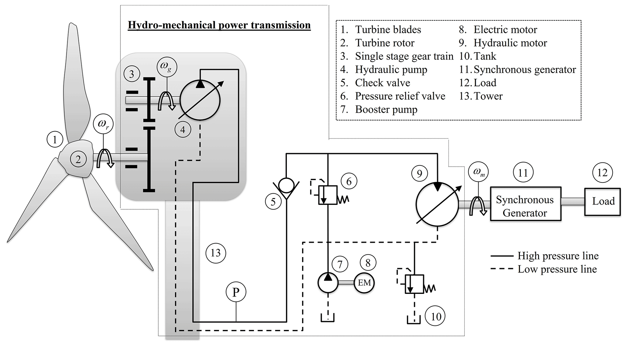
Figure 1 presents the proposed wind turbine power generation system (WTPGS), which includes a wind turbine, a hydromechanical hybrid power transmission unit, synchronous generator, and a load. The wind turbine contains three vertical blades which are connected to each other at the hub. The hub is connected with low-speed turbine rotor, which is coupled with the input shaft of the SSPGT. The purpose using the SSPGT is to magnify the rotational speed, obtained from the turbine rotor due to its positive gear ratio. The output shaft of the gear train is coupled with a variable displacement hydraulic pump, which converts the available mechanical energy into the hydraulic energy. The SSPGT and the hydraulic pump are installed on the hub of the turbine, and these are protected by the nacelle. The wind turbine structure is supported by a tower, which is normally made up of tubular steel. The hydraulic pump supplies flow to the hydraulic motor that converts the hydraulic energy into the mechanical energy. The hydraulic motor is coupled with the synchronous generator. The generator produces electricity, which operates the load of the system. The proposed system entails multiple energy domains like aerodynamics, mechanical, hydraulic, and electrical. However, this study focused on the aerodynamics, mechanical, and hydraulic energy interaction domains. The modeling of the synchronous generator is excluded from the study.
The present system is a multi-energy domain system. Therefore, the present model is developed in a modular manner consisting of several submodels. Finally, all submodels are assembled to form a global model. The submodels are the turbine blade model, SSPGT model, and HPT model. Thereafter, the complete model is developed and simulated.
3.1 Wind turbine blade model
In the present study, the aerodynamic model of the blades is carried forward from Mahato et al. (2018), and its validated bond graph model has been used for further analysis of the proposed WTPGS. It is considered that the blades are rotated with a horizontal axis, and all blades are fixed at the turbine hub. The aerodynamic blade model is generated by assuming that the blades are long, slender, and flexible. In addition, these adhere to the principle of the twisted cantilever beam. The blade element momentum (BEM) theory (Mukherjee et al., 2006) and the Rayleigh beam model (Mukherjee et al., 2006) have been used to develop the blade model. The blades are divided into a number of elements, and its rotary inertia is taken care of during modeling. Also, its shear deformation is ignored. An aerodynamic force is exerted to the elements of the turbine blade due to the wind. The detailed blade model of the wind turbine using the bond graph technique is available in multiple articles (Sanchez and Medina, 2014; Khaouch et al., 2016; Mahato et al., 2018). According to the said studies, the bond graph model of the turbine blades is validated under the consideration of applying a real wind velocity profile of a 750 kW based wind turbine (available in Sanchez and Medina, 2014). The wind turbine is operated under the following conditions:
where the optimal speed of the turbine rotor (ωr_opt) depends on the wind velocity (vwd), rotor radius (rrr), and . The λtsr_opt is a dimensionless parameter, and its estimated numerical value is 8 (Mahato et al., 2018). The torque and power available at the turbine rotor shaft are expressed as
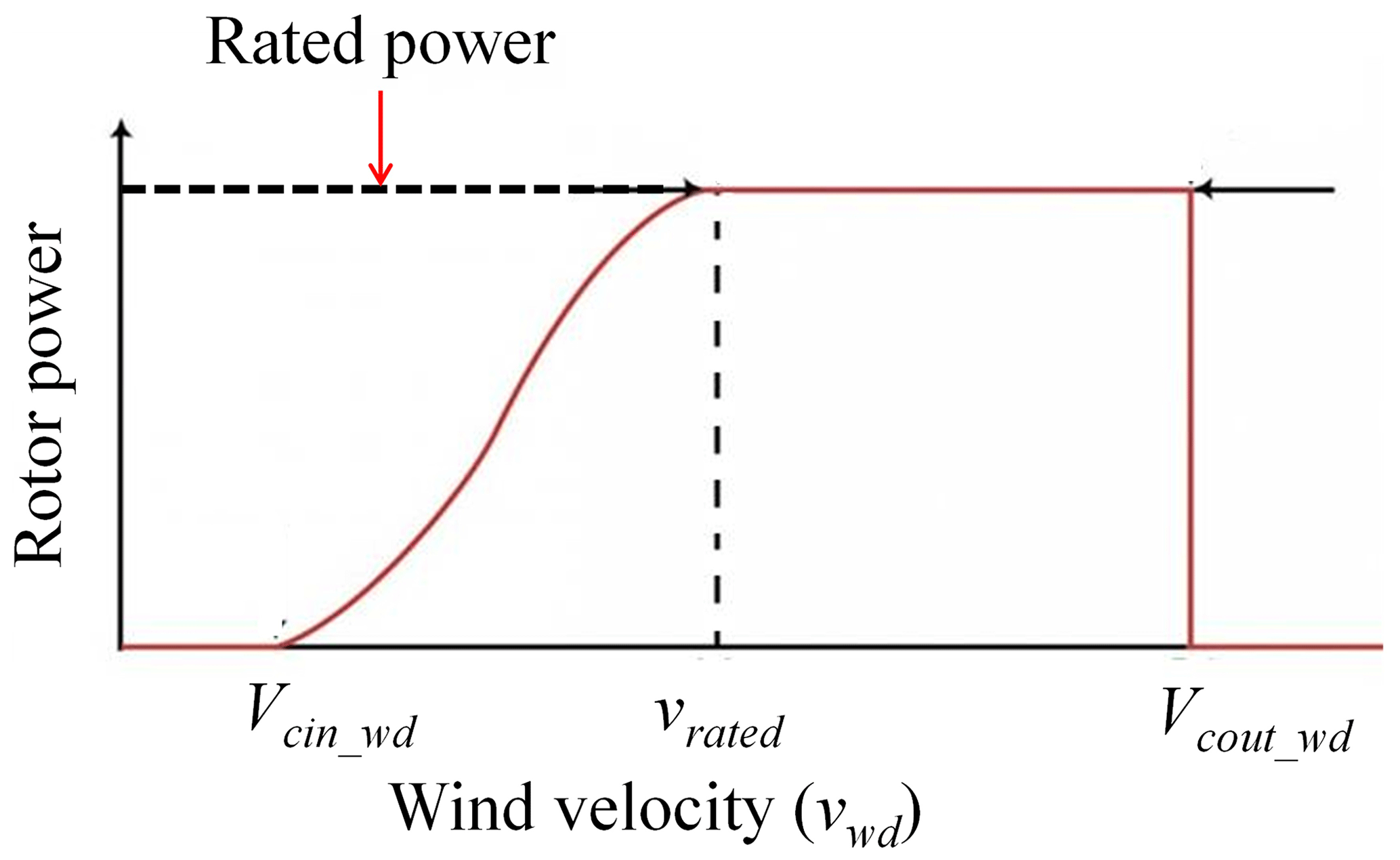
Figure 2 illustrates a typical power curve of a normal wind turbine. When wind velocity (vwd) is more than the cut-in wind velocity (vcin_wd) (it is normally between 3–6 m s−1), the turbine blades start rotating due to the aerodynamics force exerted on it, and hence started to generate torque (Twtr) and power (Pwtr) from the turbine rotor. The generated torque and the power are the functions of the air density (ρair), rrr, vwd, angular speed of the rotor (ωr), blade pitch angle (β), tip speed ratio (λ), torque coefficient (Ctco), and power coefficient (Cpco). The Cpco is expressed as the fraction of the power extracted from the wind, and its maximum numerical value is about 0.59, as per the Betz limit (Betz, 1926). The power generation is nonlinear when the vwd is found to be in between vcin_wd and rated wind speed (vrated). Thereafter, when the vwd reaches to the vrated, the turbine develops maximum power from it. This is also known as rated power of the rotor turbine. With the further increase of vwd continuously, the power generated from the turbine remains constant until it eventually hits the vcout_wd. At this stage, the turbine will shut down to prevent unnecessary strain on the rotor (Johnson, 1985).
The aerodynamic force applied to the blade elements is estimated by multiplying a modulus factor (μima) and vwd. The μima is variable and it depends on the air density (ρair), inflow angle (αi), lift and drag force coefficients (Clfi and Cdfi), axial induction factor (ai), local chord value (ci), and elemental blade length (li). Therefore, the aerodynamic force can be expressed as
The inflow angle (αi) is variable with the change of axial and tangential induction factors (ai and ), vwd, ωr, and position of the control volume (ri). It is expressed as
The induction factors along the axial and tangential direction depend on the lift and drag force components and the local solidity . These are expressed as
Equations (5)–(7) are interconnected to each other. To estimate the suitable value of ai, , and αi, an iteration cycle is performed until the values of and αi are not converged. The details of the iteration steps are available in the article published by Mahato et al. (2018).
The rotor speed (ωr) is obtained from the force balance equation at turbine rotor, and it is expressed as
where is the stiffness of beam element of the nth blade and n is the number of blades in the wind turbine. In this study, the number of the blades is 3. The y1n and y2n are the translational displacements, and δ1n and δ2n are the rotational displacements at both ends of the nth beam. The of each beam element is represented by all four generalized displacements, and it is expressed in terms of the length of the beam element (l) and its flexural rigidity (EI) (refer to Eq. 9).
The damping matrix of the structure () is estimated by multiplying the coefficient of structural damping (μ) and . The assumptions that are considered to estimate the rotor speed are as follows: negligible bending moment at the tip of the blade and the root of the blade is rigidly connected with the hub of the turbine, i.e., vbound=0. The total rotary inertia at the hub (Jtotal) is estimated as the summation of the rotary inertia of the hub itself (Jhub) and 3 times of the blade inertia (Jblade), i.e., . The bhub, Rms, and Kms are the viscous damping at bearing, viscous damping at main shaft, and stiffness of the main shaft, respectively.
3.2 Single-stage planetary gear train model
The single-stage planetary gear train is connected between the turbine rotor and hydraulic pump. The wind power is extracted by the turbine blades, and it is available at the turbine rotor in the form of mechanical energy. The same mechanical power is transmitted to run the hydraulic pump using the single-stage planetary gear train. Generally, it is a three-stage gear train, i.e., planetary stage and two more parallel stages used in wind turbines. In this study, only the planetary stage of the gear train is coupled with the power hydraulic system (refer to Fig. 3) (Tsai et al., 2010).
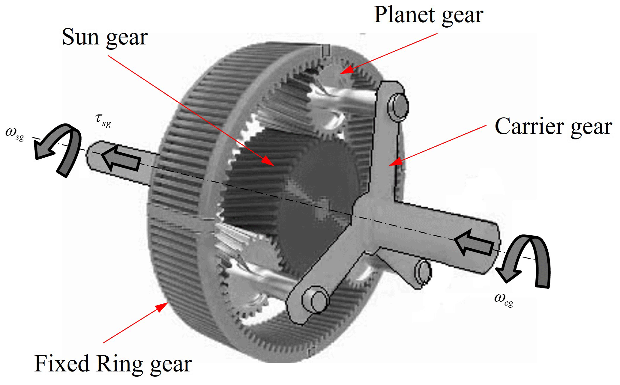
From Fig. 3, three planet gears are engaged with a ring gear and a sun gear. The function of the carrier is to grip all planet gears. The planet gears work on two kinematic modes, such that it revolves around the sun gear and auto-rotates around its own axis. The operating mode of the planetary gear is dual inputs (primary input is angular speed of the carrier ωcg and secondary input is angular speed of the ring gear ωrg) and one output, i.e., the angular speed of the sun gear (ωsg).
During modeling of the system, it is considered that the viscous friction loss exists at the couplings between the shaft of the turbine rotor and the input shaft of the SSPGT or shaft of the carrier gear, and between the output shaft of the SSPGT or sun gear shaft and hydraulic pump shaft. But the loss amount is very little. Therefore, the angular speed of the carrier gear is slightly lower than the rotor speed, and it can be estimated as
where Rms and Kms are the viscous resistance and stiffness of the shaft bearing, respectively; and Zr, Zs, and Jcg are the teeth number of the ring gear, sun gear, and rotary inertia of the planetary gear, respectively. The torque of the ring (τrg) and the sun gear (τsg) is estimated as
where Krp and Ksp are the mesh stiffness among planetary-ring gear and planetary-sun gear, respectively; and Zp is the teeth number of the planetary gear. The ring gear is fixed, and its angular speed is considered to be zero. The angular speed of the speed planetary gear (ωpg) and the sun gear (ωsg) are expressed as
where ωp is the angular speed of the hydraulic pump.
3.3 HPT system model
The HPT unit of the hybrid power transmission system is connected between the gear train and the electrical generator. The HPT unit compromises of a hydraulic pump, check valve, relief valve, booster pump, and a hydraulic motor. The hydraulic pump converts the available mechanical energy of the output gear shaft into the hydraulic energy, whereas the hydraulic motor converts the hydraulic energy into the mechanical energy that is available at the electric generator shaft. Thereafter, the generator produces electricity and supplies it to the load location points. Some of the assumptions that are considered during the development of the HPT model are as follows:
-
Fluid inertia is negligible.
-
Fluid properties are unaltered with the variation of temperature.
-
Turbulence effect has been ignored.
-
All couplings are rigid.
3.3.1 Hydraulic pump model
The input shaft of a variable displacement hydraulic pump and the output shaft of the gear train are coupled to each other. Due to the existence of the frictional loss at the coupling, the hydraulic pump speed is slightly lower than the sun gear speed. The hydraulic pump speed obtained as
where Jp and Dp are the rotary inertia and volume displacement rate of the pump, respectively. It is considered that the pump is installed in the nacelle. The hydraulic pump supplies high-pressure flow to the hydraulic motor. The pump pressure (Pp) can be estimated from the fluid bulk modulus definition as
where Kpm and ∀sw are the bulk modulus of working fluid and switched volume including line volume, respectively. In Eq. (16), the first term denotes the pump flow rate, the second term denotes internal leakage loss through the pump, and the third term represents the flow rate through the relief valve. The Rplkg and Rrlv are the leakage resistance of the pump and relief valve resistance, respectively.
3.3.2 Hydraulic motor model
The hydraulic motor converts the hydraulic power into the mechanical power. The output shaft of the motor is coupled rigidly with an electric generator shaft. The motor pressure (Pm) is estimated similarly to pump pressure, and it is expressed as
where Dm and Rmlkg are the volume displacement rate and leakage resistance of the hydraulic motor, respectively.
3.3.3 Relief valve model
The relief valve is used for safety purposes, and the flow rate () through it can be modeled as
where Cd, arlv, Patm, ρf, and Pset are the flow discharge coefficient, relief valve port area, atmospheric pressure, fluid density, and relief valve set pressure, respectively.
3.3.4 Check valve model
Check valve is a device used in hydraulic systems to restrict the backflow of the system. It allows flow in one direction only. The flow rate through the check valve () is modeled as
where Cd_chkv, achkv, and Pc are the coefficient of discharge, port opening area, and chamber pressure of the check valve, respectively.
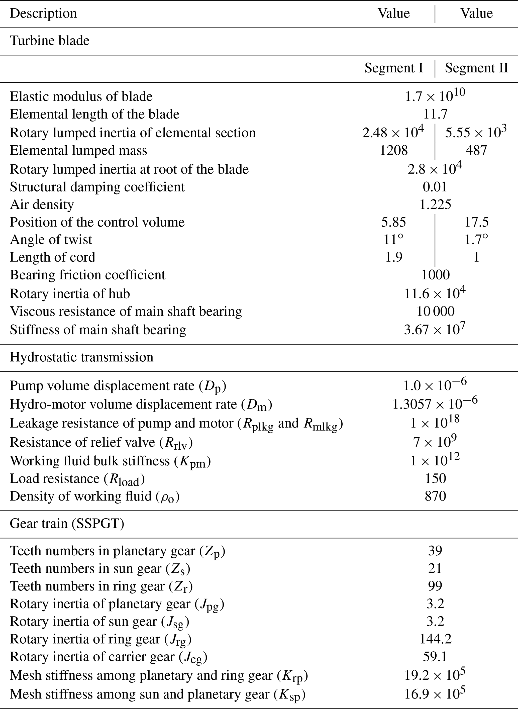
To analyze the dynamic performance of the proposed WTPGS system, a real dataset of 750 kW based wind turbine is used for reference. For the study, the dynamic model of the turbine blades is carried over from Mahato et al. (2018), and the rest of the model of the HMHPT technology is developed. Further, the blade model is assembled with the HMHPT model to make a global model. The simulation parameters and its value are tabulated in Table 1. The parameters related to the wind turbine blade are taken from a published paper (Mahato et al., 2018), and the planetary gear train-related parameters and values are collected from another published paper (Sanchez and Medina, 2014). The parameters related to the hydraulic system are taken from an experimentally validated paper (Mahato et al., 2017). However, the stiffness, viscous resistance, and load resistance are manipulated to obtain optimized results. Note: all the parameter values are in SI units. To solve the system differential equations, the well-known fifth-order Runge–Kutta–Gill method is used, and the relative truncation error is chosen as 5 × 10⁻⁶. The global model of the proposed wind power development system is simulated twice by supplying real wind speed data and user-defined variable wind speed input data.
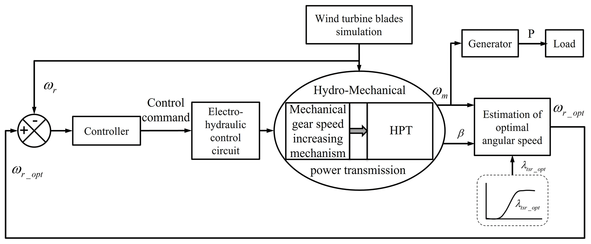
The simulation diagram to obtain optimum rotor speed of the complete wind turbine system is shown in Fig. 4. It is comprised of the wind turbine blades, hydromechanical power transmission, and the generator. The wind turbine blades modal is simulated in SYMBOLS SHAKTI software using bond graph technique. The hydromechanical power transmission is comprised of mechanical gear that includes speed increasing mechanism and the hydraulic power transmission (HPT) units. The HPT is operated by the electro-hydraulic control circuit controlled by the control command from the controller to track the optimal wind turbine rotor speed, ωr_opt. It is calculated by the measured parameters from HPT and the optimal tip speed ratio (λtsr_opt), as per Eq. (1). The optimal tip speed ratio control method is employed to achieve the maximum power point tracking (MPPT) by regulating the HPT due to its easy implementation, high-power transmission capability, and low cost. The hydro-motor of the HPT is coupled to a generator, which generates electricity and supplies it to the power supply locations.
4.1 System responses for a real dataset of wind speed
The input real wind velocity (vw) is presented in Fig. 5a, and its value varies from almost 9–13 m s−1 (Mahato et al., 2018). The simulation results are presented in Fig. 5b, c, d, and e. The aerodynamic force that developed in the turbine blades is presented in Fig. 5b. It depends on the wind speed and estimates as per Eq. (4). The average force developed in the first element and second element of each blade is about 467 and 2108 N, respectively.
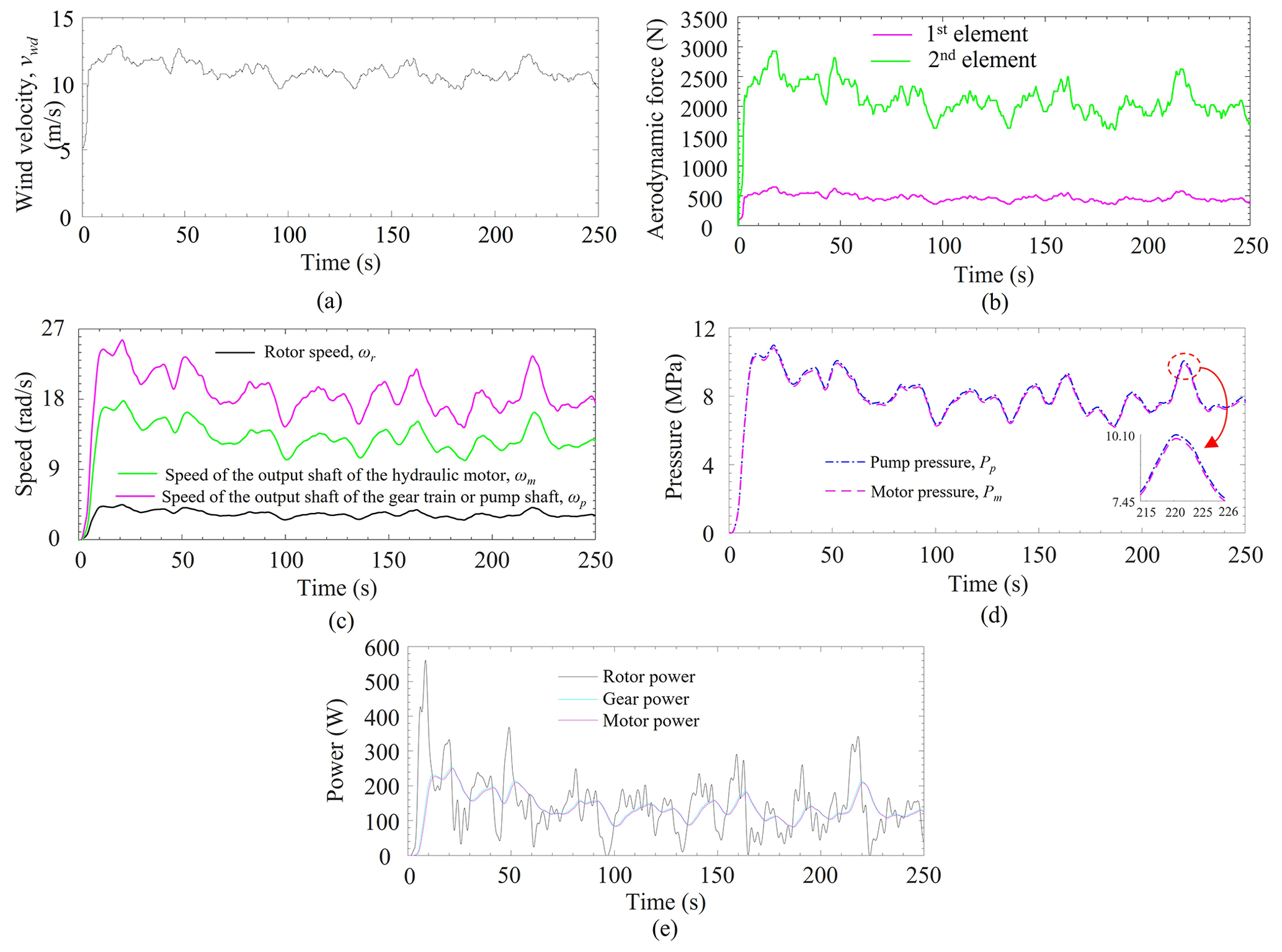
Figure 5(a) Real wind velocity (Sanchez and Medina, 2014). (b) Aerodynamic forces. (c) Speed of turbine rotor, hydraulic pump, and hydraulic motor (ωr, ωp, and ωm). (d) Pressure at pump and motor plenum (Pp and Pm). (e) Power developed at rotor, gear, and motor shaft.
The angular speed of the rotor depends on the wind velocity, and it increases with increase of wind speed or vice versa. From Fig. 5c, the average value of the angular speed of the rotor of the wind turbine is about 3.2 rad s−1, and it fluctuates between 2.5 to 3.9 rad s−1 for a time of 250 s. As the rotor shaft is directly coupled with the SSPGT box, its transmission gear ratio is 6. Hence, the angular velocity of the output shaft of the gearbox is almost 6 times higher than the input shaft of the gearbox. Thus, the gear train has been used to magnify the angular speed. In Fig. 5c, the response of the gearbox shows that the average angular speed of the output shaft of the gear train or speed of the pump is about 18.6 rad s−1, and it fluctuates between 14.9 to 25.6 rad s−1. The output shaft of the gearbox is coupled with the hydraulic pump of the HPT unit. The hydraulic pump supplies flow to the hydraulic motor, which is coupled with the generator. Therefore, the hydraulic motor rotates with an average angular speed of 12.98 rad s−1, and it fluctuates between almost 9–18 rad s−1. The rotational speed of the hydraulic pump is slightly higher than the electric generator due to some losses through the hydraulic pump and the hydraulic motor. Similarly, the pressure at the pump plenum is slightly higher than the hydraulic motor. The maximum pressure obtained at the pump plenum is about 11 MPa. The pressure developed at the hydraulic pump and the hydraulic motor plenum is shown in Fig. 5d. Figure 5e represents the power developed at the rotor, gear, and motor shaft of the system. The power fluctuation at the rotor of the turbine is slightly higher than the power developed at the gear shaft and the motor shaft. However, the available power at the motor shaft is slightly lower than the power at the gear shaft due to the leakage of HPT.
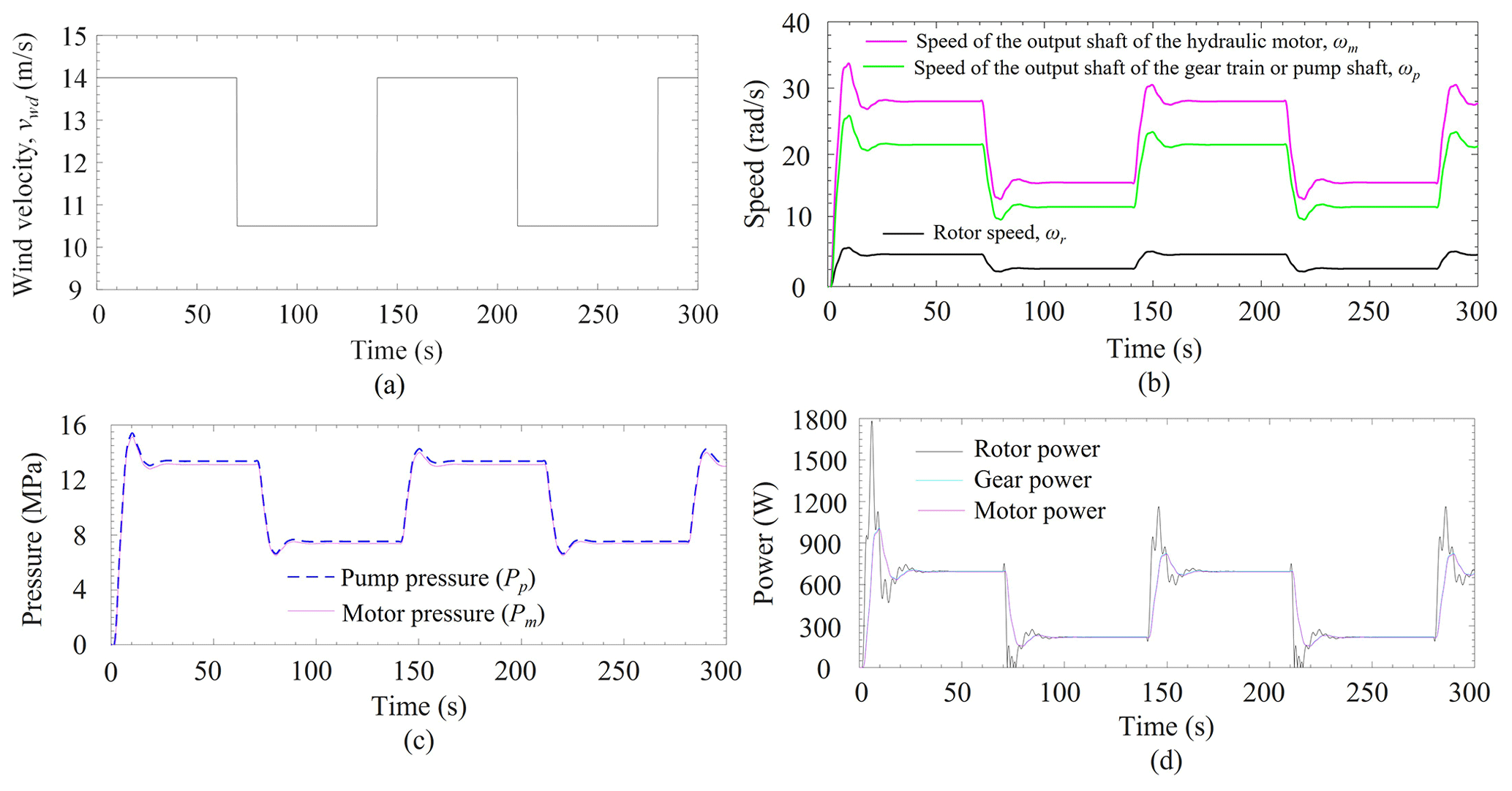
Figure 6(a) User-defined variable wind velocity (Mahato et al., 2018). (b) Speed of turbine rotor, hydraulic pump, and hydraulic motor (ωr, ωp, and ωm). (c) Pressure at pump and motor plenum (Pp and Pm). (d) Power developed at rotor, gear, and motor shaft.
4.2 System responses for user-defined variable wind speed
This section describes the responses obtained from the simulation of the global model of the proposed WTPGS, where the input wind velocity is user-defined, variable in nature, and its value varies from 14–10.5 m s−1 (refer to Fig. 6a).
The rotor speed changes according to wind speed, and it fluctuates from 3.1–6.3 rad s−1, which is present in Fig. 6b. Similarly, the input speed for the hydraulic pump shaft (ωp) and output speed of the hydraulic motor shaft (ωm) is plotted in the same Fig. 6b. It is found that the ωp fluctuates between 14–36 rad s−1 and ωm fluctuates between 10.8–25 rad s−1. Due to some leakage and other losses, the hydraulic motor rotates with slightly lower speed compared to the hydraulic pump. Moreover, the pressure development at the pump plenum is also higher than the motor plenum pressure (refer to Fig. 6c). The maximum pressure observed at the pump plenum is almost 15 MPa. Similarly, the power developed at the rotor, gear, and motor shaft of the system is shown in Fig. 6d. The power fluctuation at the rotor of the turbine is slightly higher than the power developed at the gear shaft and the motor shaft. However, the available power at the motor shaft is slightly lower than the power at the gear shaft due to the leakage of HPT.
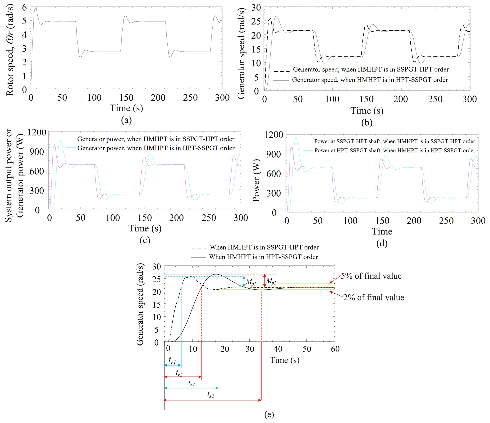
Figure 7Responses when order of the SSPGT and the HPT are swapped. (a) Rotor speed. (b) Generator speed comparison between SSPGT–HPT and HPT–SSPGT-based HMHPT. (c) Output shaft power, i.e., generator shaft power comparison between SSPGT–HPT and HPT–SSPGT-based HMHPT. (d) Intermediate shaft power comparison between SSPGT–HPT and HPT–SSPGT-based HMHPT. (e) Transient response analysis between SSPGT–HPT and HPT–SSPGT-based HMHPT.
4.3 Simulation responses when the order of the SSPGT and the HPT are swapped (i.e., HPT–SSPGT-based HMHPT)
This section describes the responses obtained from the simulation when the order of the SSPGT and the HPT are swapped (i.e., HPT–SSPGT) in the proposed HMHPT system. In such a connection, the turbine rotor shaft is coupled to the hydraulic pump shaft, the hydraulic motor shaft is coupled to the SSPGT input shaft, and the SSPGT output shaft is coupled to the electric generator shaft. During this connection, all other conditions and simulation parameters are kept the same as with the previous connection, i.e., SSPGT–HPT in HMHPT. The simulation responses of the said system are shown in Fig. 7. From Fig. 7a, it is found that the turbine rotor speed is unchanged when the order of the SSPGT and the HPT are swapped (refer to Figs. 6b and 7b). Figure 7b represents the comparison of the system output speed, i.e., generator speed for both SSPGT–HPT and HPT–SSPGT combinations. It is observed that the system output speed is almost the same for both combinations. Similarly, the system output power, i.e., power at the generator shaft, and the power at the intermediate shaft of the SSPGT–HPT and HPT–SSPGT combinations are compared in Fig. 7c and d, respectively. It is observed that the power output from both SSPGT–HPT and HPT–SSPGT combinations of the HMHPT is almost the same. However, the controllability of the HPT–SSPGT-based HMHPT is weak as the settling time (ts), maximum overshoot (Mp), and rise time (tr) of the said responses are higher in comparison to the SSPGT–HPT-based HMHPT (refer to Fig. 7e). The settling time is the time required for the response to reach and stay within a range (normally 2 %–5 %) of the final value, whereas the maximum overshoot is the maximum peak value from the steady-state value of the response. The rise time is defined as the time required to reach its steady-state value the first time (refer to Fig. 7e) (Ogata, 2010). The higher numerical values of the ts, Mp, and tr are not desirable for a good, controlled system. Therefore, the controllability of the SSPGT–HPT-based HMHPT is higher than the HPT–SSPGT-based HMHPT.
4.4 Response influences due to the pump and motor leakage variations
This section describes the influence of motor speed and the power due to the variation of leakage resistance of the pump and the motor in an HPT system. It is considered that the numerical value of the leakage resistance for both pump and the motor are the same, i.e., Rplkg=Rmlkg. From Figs. 8 and 9, the leakage resistance is varied to 1 × 10¹³, 1 × 10¹⁴, 1 × 10¹⁵, 1 × 10¹⁶, and 1 × 10¹⁸ N s m−5. From Fig. 8, the motor speed (ωm) is almost the same when the leakage resistance is varied to 1 × 10¹⁵, 1 × 10¹⁶, and 1 × 10¹⁸ N s m−5. But the ωm is decreased with decreasing the leakage resistance, and a significant change is observed when the leakage resistance value is 1 × 10¹³ N s m−5. Similarly, the available power at the motor shaft is almost the same when the leakage resistance is varied to 1 × 10¹⁵, 1 × 10¹⁶, and 1 × 10¹⁸ N s m−5, and it is decreased with decreasing the leakage resistance (refer to Fig. 9). The ωm and the motor power are both found to have a lower value when leakage resistance is considered to be 1 × 10¹³ N s m−5. Therefore, it is concluded that the higher leakage resistance value provides better power output from the system.
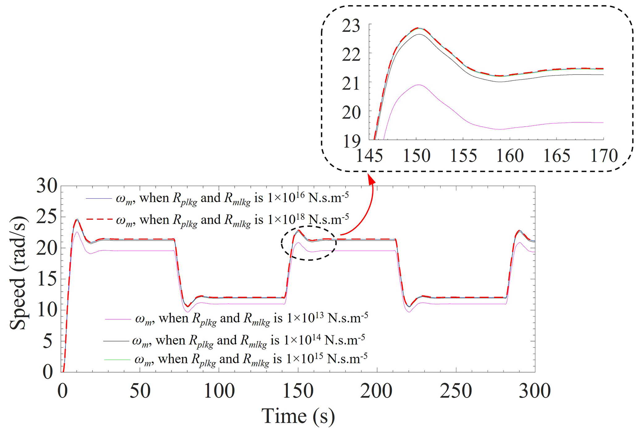
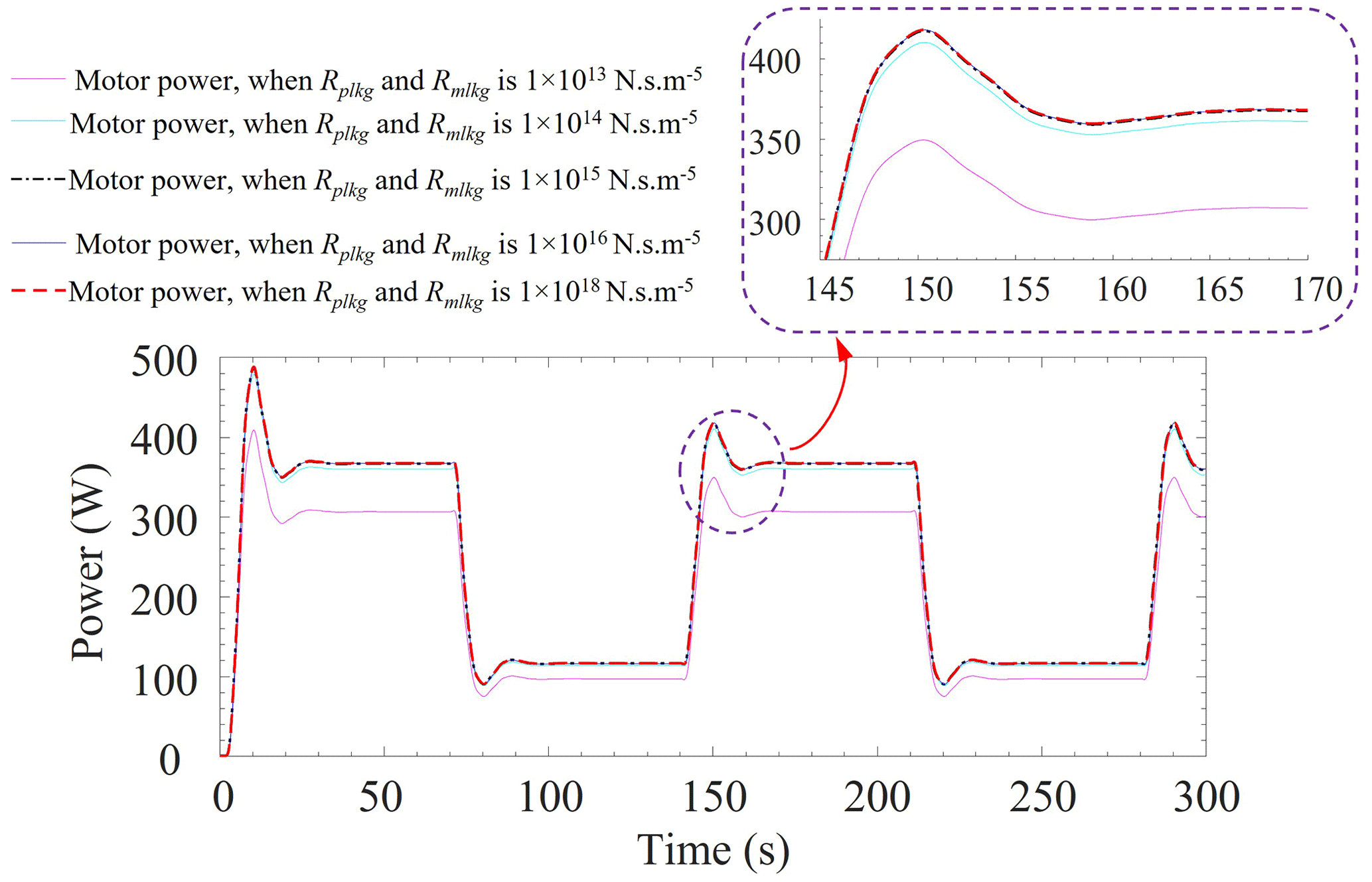
Figure 9Influence of power output at motor shaft due to the variation of leakage resistance.
This study presents a hybrid power transmission technology, i.e., HMHPT, for transmitting power from the turbine rotor shaft to the electric generator in a wind turbine application. A dynamic model of WTPGS is developed and simulated to analyze the performance of the proposed HMHPT technology. The global model of the WTPGS is segmented in two different areas, such as the aerodynamic model of the turbine blades and dynamic model of the HMHPT. An existing aerodynamic model of the turbine blades is used for performance analysis of the proposed HMHPT technology. It is a combined concept of mechanical power transmission and an HPT system. The findings that are obtained from the study are listed below:
-
The normally used mechanical power transmission or the HPT can easily be replaced by a hydromechanical hybrid power transmission technology in wind power application.
-
In HMHPT, the HPT helps to improve the controllability, and mechanical power transmission helps to obtain higher speed of the electric generator due to its positive gear ratio. Therefore, using HMHPT provides both benefits of system controllability as well as higher generator speed, achieved using a signal system.
-
The proposed hybrid power transmission eliminates the needs of the frequency converter, which is a necessary device in an electrical generator for WTPGS whenever mechanical power transmission is used in the system.
-
The power generation from the proposed system is higher when pump and motor leakage resistance is considered as a higher value.
-
If the order of the SSPGT and the HPT are swapped in the proposed HMHPT, the settling time, maximum overshoot, and rise time of the system responses are increased. Hence, the controllability of the system decreases.
-
The pump and the motor leakages adversely affect the system's performances, such as hydro-motor or generator speed and its available power.
The proposed work is simulation based. The robustness of the proposed hybrid technology in wind turbine applications can be enhanced by performing an experimental validation. Also, a suitable energy storage system and a control technique may reduce the wind power fluctuation, hence reducing the load shedding in the wind power supply location.
The datasets generated during and/or analyzed for the current study are available from the corresponding author on reasonable request.
ACM conceived the project and design, decided on the methodology, and supervised the work. DK performed the simulation work, critical analysis, and prepared the draft.
The contact author has declared that neither of the authors has any competing interests.
Publisher’s note: Copernicus Publications remains neutral with regard to jurisdictional claims in published maps and institutional affiliations.
The first author thanks to Birla Institute of Technology, Mesra for allowing him to carry out research and other supports.
This paper was edited by Daniel Condurache and reviewed by two anonymous referees.
Arturo Soriano, L., Yu, W., and Rubio, J. D. J.: Modeling and control of wind turbine, Math. Probl. Eng., 2013, 982597, https://doi.org/10.1155/2013/982597, 2013.
Betz, A.: Wind energy and its exploitation by windmills, Van-denhoeck und Ruprccht, Gottingen, 64 pp., 1926.
Buhagiar, D., Sant, T., Micallef, C., and Farrugia, R. N.: Improving the energy yield from an open loop hydraulic offshore turbine through deep sea water extraction and alternative control schemes, Energy, 84, 344–356, 2015.
Fan, Y., Mu, A., and Ma, T.: Study on the application of energy storage system in offshore wind turbine with hydraulic transmission, Energ. Convers. Manage., 110, 338–346, 2016.
Jelaska, D., Podrug, S., and Perkušić, M.: A novel hybrid transmission for variable speed wind turbines, Renew. Energ., 83, 78–84, 2015.
Jiang, Z., Yang, L., Gao, Z., and Moan, T.: Numerical simulation of a wind turbine with a hydraulic transmission system, Enrgy. Proced., 53, 44–55, 2014.
Johnson, G. L.: Wind energy systems, Prentice-Hall, Englewood Cliffs, NJ, ISBN 978-0139577543, 1985.
Khaouch, Z., Zekraoui, M., Bengourram, J., Kouider, N., and Mabrouki, M.: Mechatronic modeling of a 750 kW fixed-speed wind energy conversion system using the Bond Graph Approach, ISA T., 65, 418–436, 2016.
Kumar, D., Mahato, A. C., Prakash, O., and Kumar, K.: Priority flow divider valve and its dynamic analysis using various hydraulic drive systems: a bond graph approach, Mech. Sci., 13, 459–472, https://doi.org/10.5194/ms-13-459-2022, 2022.
Kumar, R., Kumar, D., Mahato, A. C., and Tripathi, J. P.: Dynamic modeling and analysis of a hydro-mechanical power transmission system, Mater. Today-Proc., 61, 50–54, 2022.
Laguna, A. J.: Modeling and analysis of an offshore wind turbine with fluid power transmission for centralized electricity generation, J. Comput. Nonlin. Dyn., 10, 041002, https://doi.org/10.1115/1.4028110, 2015.
Laguna, A. J., Diepeveen, N. F., and Van Wingerden, J. W.: Analysis of dynamics of fluid power drive-trains for variable speed wind turbines: parameter study, IET Renew. Power Gen., 8, 398–410, 2014.
Lin, Y., Tu, L., Liu, H., and Li, W.: Hybrid power transmission technology in a wind turbine generation system, IEEE-ASME T. Mech., 20, 1218–1225, 2014.
Liu, H., Lin, Y., Shi, M., Li, W., Gu, H., Xu, Q., and Tu, L.: A novel hydraulic-mechanical hybrid transmission in tidal current turbines, Renew. Energ., 81, 31–42, 2015.
Liu, H. W., Li, W., Lin, Y. G., and Ma, S.: Tidal current turbine based on hydraulic transmission system, J. Zhejiang Univ.-Sc. A, 12, 511–518, 2011.
Liu, Y. W. and Fan, J.: Design of asymmetric double circular arc gear for large-scale high-pressure gear pumps, Adv. Mater. Res., 181, 361–365, https://doi.org/10.4028/www.scientific.net/AMR.181-182.361, 2011.
Mahato, A. C. and Ghoshal, S. K.: Various power transmission strategies in wind turbine: an overview, International Journal of Dynamics and Control, 7, 1149–1156, 2019.
Mahato, A. C., Ghoshal, S. K., and Samantaray, A. K.: Energy saving of a hydrostatic drive system by incorporating soft switch, J. Braz. Soc. Mech. Sci., 39, 1929–1945, 2017.
Mahato, A. C., Ghoshal, S. K., and Samantaray, A. K.: Reduction of wind turbine power fluctuation by using priority flow divider valve in a hydraulic power transmission, Mech. Mach. Theory, 128, 234–253, 2018.
Mitra, S., Mahato, A. C., Nag, A., and Kumar, D.: Various methodologies to improve the energy efficiency of a compressed air energy storage system, Energy Storage, 4, e315, https://doi.org/10.1002/est2.315, 2022.
Mukherjee, A., Karmakar, R., and Samantaray, A. K.: Bond graph in modeling, simulation and fault identification, IK International, New Delhi, ISBN 81-88237-96-5, 2006.
Ogata, K.: Modern control engineering, Vol. 5, Prentice hall, Upper Saddle River, NJ, ISBN 978-0-13-615673-4, 2010.
Pan, L., Gao, T., Cai, S., and Yin, X.: Design and simulation of a novel continuously variable-speed drivetrain for wind turbine, Sādhanā, 46, 1–9, 2021.
Rampen, W.: Gearless Transmissions for Large Wind Turbines: The history and Future of Hydraulic Drives, in: 8th German Wind Energy Conference, Bremen, Germany, 22–23 November 2006, Deutsches Windenergie-Institut, ISBN 9783000209887, 2007.
Sanchez, R. and Medina, A.: Wind turbine model simulation: A bond graph approach, Simul. Model. Pract. Th., 41, 28–45, 2014.
Sand, E. D. and Li, P. Y.: Incorporating a Rotatable Valve Cam to Improve the Efficiency of a Hydraulic Motor in an Inline Hydro-Mechanical Transmission (i-HMT), in: Fluid Power Systems Technology, Paper No: FPMC2022-89553, Vol. 86335, V001T01A029, https://doi.org/10.1115/FPMC2022-89553, 2022.
Tsai, M. C., Huang, C. C., and Lin, B. J.: Kinematic analysis of planetary gear systems using block diagrams, J. Mech. Design, 132, 065001, https://doi.org/10.1115/1.4001598, 2010.
Wang, L., Book, W. J., and Huggins, J. D.: Application of singular perturbation theory to hydraulic pump controlled systems, IEEE-ASME T. Mech., 17, 251–259, 2011.
Yin, X., Tong, X., Zhao, X., and Karcanias, A.: Maximum power generation control of a hybrid wind turbine transmission system based on H∞ loop-shaping approach, IEEE T. Sustain. Energ., 11, 561–570, 2019.
Yin, X. X., Lin, Y. G., Li, W., Liu, H. W., and Gu, Y. J.: Output power control for hydro-viscous transmission based continuously variable speed wind turbine, Renew. Energ., 72, 395–405, 2014.
Yin, X. X., Lin, Y. G., Li, W., and Gu, H. G.: Hydro-viscous transmission based maximum power extraction control for continuously variable speed wind turbine with enhanced efficiency, Renew. Energ., 87, 646–655, 2016.
Yu, J., Song, Y., Zhang, H., and Dong, X.: Novel design of compound coupled hydro-mechanical transmission on heavy-duty vehicle for energy recycling, Energy, 239, 122291, https://doi.org/10.1016/j.energy.2021.122291, 2022.