the Creative Commons Attribution 4.0 License.
the Creative Commons Attribution 4.0 License.
 | 17 May 2023
Study on the vibration control method of a turboshaft engine rotor based on piezoelectric squeeze film damper oil film clearance
Qingxiong Lu
Chao Li
Yangyan Zhang
Hao Fang
Guangfu Bin
In the complex environment of the battlefield and dust weather, hard objects including birds, bullets, sand and others will inevitably cause impact damage to the compressor blades of turboshaft engines. The damage will further result in fatigue vibration of the gas generator rotor and catastrophic accidents such as excessive engine vibration and even crash. The relation between oil film clearance of dampers and damping of rotor systems as well as the damping and vibration amplitude of a rotor system are analyzed. The functional relation between oil film clearance and vibration amplitude is derived. Taking the gas generator rotor of a certain turboshaft engine as an example, the rotor dynamic model of a gas generator rotor with oil film bearing clearance is constructed, and the vibration response of the rotor system under different oil film clearances is analyzed. A new type of squeeze film damper (SFD) structure with piezoelectric-driven split pads is innovatively designed, and the vibration control system of the gas generator rotor is built. In addition, experimental research on rotor fault vibration control under different oil film clearances is carried out. The results show that, within a certain range, when oil film clearance decreases, amplitude will decrease. Under the experimental conditions, when the driving voltage of the piezoelectric actuator is adjusted from 0 to 70 V, the oil film clearance decreases from 156 to 118 µm. Then, the vibration amplitude decreases and gradually reaches stability after 0.036 s, and the vibration amplitude of the rotor system decreases by 12 %. When the driving voltage of the piezoelectric actuator is adjusted to 150 V, the oil film clearance decreases to 76 µm, and the vibration amplitude of the rotor system decreases by 28 %. When the new SFD adopts a piezoelectric-driven split-pad structure, the structure can adjust quickly the oil film clearance online so as to control the vibration of the rotor system. The research results can provide a technical reference for the vibration control of turboshaft engine rotor systems.
- Article
(2442 KB) - Full-text XML
- BibTeX
- EndNote


When helicopters carry out transportation, combat and other tasks in the complex environments of battlefields and dust weather, hard objects including birds, bullets, sand and stones in the environment will inevitably enter the turboshaft engine along with the air flow. Hard objects strike engine blades for a short time, causing impact damage to compressor blades such as pits and notches. This results in high-order fatigue vibration by blade detuning, which further causes blade angle loss and accelerates the evolution of compressor rotor imbalance. On the other hand, after passing through the compressor, some particles will deposit and block the film holes of the turbine blades. These phenomena will change the distribution of the temperature field, causing non-uniform thermal deformation of the blades to produce rotor imbalance. With the accumulation and aggravation of the damage degree, nonlinear faults like rotor–stator rubbing may be caused, resulting in catastrophic accidents such as excessive engine vibration and even crashes (She et al., 2018; Li et al., 2019), which seriously endangers the safety of aircraft and personnel (Evstifeev et al., 2018; Frankel et al., 2012; Jiang et al., 2023). Therefore, it is of great engineering significance to study new vibration control technology for rotor faults of turboshaft engines to improve the safety service capability of helicopters.
In order to reduce the vibration of the device and increase its operation safety, a large number of scholars have carried out dynamic analysis and research on structures of devices (Ma et al., 2014; Wang et al., 2015; Yang et al., 2019; Chen et al., 2019; Zhao et al., 2019; Zhang et al., 2021; Shi et al., 2023a), such as blade impact damage law and blade vibration measurement. By studying the law of blade impact damage and summarizing the formation mechanisms of rotor faults, this can provide a theoretical basis for vibration control methods of the rotor system. Nicholas (2006) summarized the types of blade damage and found that burrs, pits, tears and notches were related to high-frequency fatigue vibration of blades. Sinha et al. (2011) studied the change rule of blade dynamic load with the impact time of external objects and determined the impact location of the blade dynamic load peak. Wang et al. (2020) presented an improved non-contact dynamic stress measurement method based on a fundamental mistuning model. The study provided a roadmap to measure the dynamic stress of a rotating mistuned disk. Feulner et al. (2015) established a model of hail breakage in the low-pressure compressor of a turbofan engine and found that hail breakage mainly occurred during the impact on the first-stage blade. Mohammadi and Khoddami (2020) studied the effects of impact particle size, velocity and angle on the impact behavior of compressor blades under different temperature fields by simulating the impact behavior of compressor blades. Li et al. (2021, 2023) and Bin et al. (2023) designed and built a Ti-6Al-4V alloy erosion wear test bench to study the distribution area of compressor blade erosion wear. The results showed that there were areas of wear concentrated on the pressure surface of the rotor blade and the suction and pressure surfaces of the stator blade. Moreover, the erosion wear degree of rotor blades under the design speed is obviously higher than that at other speeds, and the imbalance magnitude of different rotor blades caused by erosion damage is different. Yang et al. (2022) summarized the damage mechanism of the blade from the aspects of the impactor's size, hardness and shape and analyzed the advantages and disadvantages of the test methods. Finally, they summarized different ways of protecting against foreign-object damage, aiming at four foreign objects including sand, metal, birds and ice in this paper. Ma et al. (2013a) investigated the effects of the seal force and oil film force on the first- and second-mode instabilities under two loading conditions which are determined by API Standard 617 (Axial and Centrifugal Compressors and Expander-compressors for Petroleum, Chemical and Gas Industry Services, Seventh Edition). The results show that the second loading condition (out-of-phase imbalances of two disks) and the nonlinear seal force can mainly restrain the first-mode instability and have slight effects on the second-mode instability (Zhang et al., 2023). This paper proposes a novel diagnosis indicator for rotor systems with rub-impact faults. The experimental results reveal that the proposed indicator can help judge the different severities of rub-impact faults.
Compressor blade damage caused by external impact cannot be repaired in time during operation, so it is necessary to control the impact of fault vibration caused by damage. In order to improve the stability of the rotor system and reduce the amplitude, many scholars have carried out a large number of studies (Sivrioglu, 2007; Bin et al., 2018b; Pan et al., 2022; Shi et al., 2023b), including changing structural parameters, improving bearings, designing various dampers and optimizing control methods. In terms of changing structural parameters (Wang et al., 2016; Zhong et al., 2021), Wang et al. (2015) studied the influence law of inner and outer clearance on turbocharger vibration. The simulation results show that the speed for the appearance of fractional frequency is not identical and that the amplitude magnitude is different under the four kinds of bearing manufacturing tolerance limit clearances. Ma et al. (2021) investigated the effects of different structural parameters such as bearing clearance, imbalance and centralizing spring stiffness on the steady-state responses of the dual-rotor system. Bin et al. (2018a) studied the imbalance (me) vibration caused by operational wear and uneven carbon absorption in compressor and turbine wheels. The research shows that, as the imbalance magnitude increases from 0.05 to 0.2 g mm, the vibration component changes from mainly 0.12× to synchronous vibration 1×. Bin et al. (2021) studied the influence of dynamic ring / speed ratio change on the vibration response of a floating ring bearing. The results show that when the ring / speed ratio is between 0.18 and 0.24, the rotor is in a good operating state. Ma et al. (2013b) investigated how the eccentric phase difference between two disks influences the oil film instability (the first-/second-mode whirl/whip) in a rotor-bearing system. In terms of improving bearings (Chasalevris and Dohnal, 2015; Pinte et al., 2010), Choy and Halloran (1982) designed a hydrostatic squeeze film damper (SFD) to reduce vibration based on the concept of hydrostatic bearing. However, this kind of damper requires an additional fuel supply device that provides a high oil pressure, so it is difficult to apply in aero-engines. Chasalevris and Dohnal (2014) proposed a passive adjustable sliding bearing, which can effectively reduce the resonance amplitude of the journal, but the damping frequency band is limited, and most of them are suitable for high-frequency vibration. In terms of designing various dampers (Lu et al., 2019), Forte et al. (2004), Wang et al. (2019) and Piccirillo et al. (2015) studied the vibration reduction effect and strategy of a Mr Fluid damper in a rotor system. Zhu (2001) proposed the magnetorheological fluid SFD that changes the flow form of a magnetic fluid by applying a controllable magnetic field in the oil film region so as to control the dynamic characteristics of the damper and effectively control the overcritical vibration of the rotor. However, the operating temperature range of the ERF/MRF (electrorheological fluid/magnetorheological fluid) is narrow, and the zero electric field viscosity is high. After a period of use, particle deposition will occur, resulting in poor stability, which will further affect its popularization and application. Das et al. (2008) found that the electromagnetic damper can eliminate the imbalanced vibration generated by the rotor operation in the process, but the control system of electromagnetic force is difficult to realize. In terms of optimizing control methods, Mu et al. (1991) proposed an active SFD, which uses a hydraulic mechanism to control the axial position of the outer ring of the damper. The device can actively adjust parameters such as the clearance and width of the oil film so that active control of its damping characteristics can be realized. Santos and Ncoletti (2001) changed the lubrication performance of the sliding bearing through the hydraulic control system. It was found that this method could reduce the vibration of rigid rotor systems. However, the above two methods are inflexible and cannot meet the demands of rapid control of rotor fault vibration.
Piezoelectric materials can exhibit piezoelectric and inverse piezoelectric effects due to different transformation directions. In recent years, due to the development of piezoelectric materials, various new types of piezoelectric materials have emerged, such as piezoelectric ceramics, which have received widespread attention. On the one hand, piezoelectric ceramics can be used as both sensors and actuators. On the other hand, piezoelectric ceramics have the advantages of fast response, large output force and displacement, and simple installation. Therefore, piezoelectric ceramics are very suitable for vibration control of rotor systems. Macro Fiber Composite (MFC) is a type of piezoelectric material that embeds piezoceramic nanoparticles in a polymer matrix for active control. By optimizing the MFC modeling approach, the asymmetric hysteresis phenomenon of MFC actuators can be accurately modeled (Fu et al., 2022), thereby enhancing the control performance of piezoelectric materials. In the late 1980s and early 1990s, Palazzolo et al. (1989) and Pritchard and Adelman (1990) first carried out research on rotor vibration active control based on piezoelectric actuators. In this century, Malgaca et al. (2015) found that the amplitude of rotating blades could be inhibited by piezoelectric materials installed at the roots of blades. Horst and Wölfel (2004) carried out active control of rotor mass imbalance vibration by attaching piezoelectric materials to the rotating shaft, and the effectiveness of this method was verified by simulation and experiments. Jamshidi and Jafari (2021) evaluated nonlinear vibration of a conical shell with a piezoelectric sensor patch and a piezoelectric actuator patch. The results showed that the piezoelectric patches can have higher impacts on the free nonlinear vibration response of conical shells, and they can decrease the vibration amplitude dramatically. In order to solve the problem of imbalanced vibration of the aerostatic spindle, Chen et al. (2023) designed a new type of controllable radial aerostatic bearing by combining piezoelectric ceramics to reduce the vibration amplitude due to the imbalance. Singh et al. (2021) proposed active vibration control of a smart cantilever beam using a poling-tuned piezoelectric actuator. Rossi et al. (2023) proposed a new piezoelectric active system and developed an analytical model to mitigate the torsional vibrations using the bending moments exerted by the PZT (piezoelectric) actuators. Hashemi et al. (2022) studied a smart active vibration control system containing piezoelectric actuators, jointly with a linear quadratic regulator controller, to control transverse deflections of a wind turbine blade.
Therefore, this paper analyzed the relation between oil film clearance of the damper and damping of a rotor system and the damping and vibration amplitude of a rotor system. The functional relation between oil film clearance and vibration amplitude was derived. The results show that, within a certain range, when oil film clearance decreases, amplitude will decrease. Taking the gas generator rotor system of a certain turboshaft engine as an example, the dynamic model of a gas generator rotor with oil film bearing clearance is established. At the same time, the vibration response of the rotor system under different oil film clearance is analyzed. A new type of SFD structure driven by piezoelectric split pads is innovatively designed. The vibration control system of the gas generator rotor was built to control the fault vibration of the rotor system. This study provides a reference for vibration control methods after the impact damage of the rotor system of the turboshaft engine caused by fault vibration.
The general differential equation of motion of the rotor system is as follows:
where M is the mass matrix of the rotor system, C is the damping matrix, K is the stiffness matrix and x is the radial displacement.
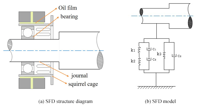
The SFD structure diagram is shown in Fig. 1a, and the SFD mode is shown in Fig. 1b. The stiffness k of the elastic support system is the total stiffness of bearing stiffness k1 and squirrel-cage elastic support stiffness k2 connected in parallel with oil film stiffness k3. The sum of the damping ratio produced by bearing damping c1 and squirrel-cage elastic support damping c2 in an aero-engine is usually less than 5 %, which is far less than the damping ratio produced by SFD damping c3. Therefore, the total damping c of the elastic support system can be regarded as SFD damping c3.
When the steady-state synchronous circle process is performed around the center line of the bearing by rotating the center of the journal, the damping stiffness and damping are calculated by the half oil film theory of the short bearing based on the Reynolds equation. We can obtain
where C is the damping value of the equipment (Ns m−1), π is 3.141592653, μ is the viscosity of lubrication (Cst), R is the radius of the damper clearance area (m), L is the axial length of the clearance (m), ε is eccentricity and c is the damping oil film clearance (m). Thus, oil film damping is inversely proportional to the third power of the oil film clearance.
From Eq. (1), when F = 0, the system motion is free vibration, and Eq. (1) is as follows:
According to the vibration equation, we have
where ω is the angular frequency. δ is the damping coefficient.
Suppose that
Based on the initial conditions, P and Q can be obtained:
According to Eq. (6), Eq. (4) can be expressed as
Hence,
When , x(t) is a positive peak value of amplitude.
So,
Taking the logarithm of both sides of Eq. (9), we can obtain
where ω0 is the natural angular frequency.
Set
According to Eqs. (2) and (11), Eq. (10) can be expressed as
Set
Substituting Eq. (13) into Eq. (12), we can obtain
For a certain system, and ε can be considered constants. So, B can be a constant.
Therefore, when c decreases, δ will increase and ω will decrease, resulting in an increase in A.
It can be concluded that, within a certain range, when c decreases, C and δ can increase and ω can decrease, causing a decline in A. However, within a certain range, when oil film clearance decreases, amplitude will decrease.
3.1 Finite-element modeling of a gas generator rotor
The actual structure of a turboshaft engine is extremely compact and complex, making it difficult to conduct rotor dynamics analysis and research. Therefore, it is often necessary to perform similar equivalence for the engine in research. According to the structural form of the gas generator rotor system of the prototype, the structures such as the casing, blades, bolts, toothed-end faces, and tie rods are ignored, and key structural parameters such as the support, shaft, and turntable of the gas generator rotor system are retained to ensure that similar models accurately reflect the dynamic characteristics of the prototype. The compressor, gas turbine, and blade of a prototype gas generator rotor system are equivalent to a mass disk, and the shaft is equivalent to a chrome-plated optical shaft. Taking the gas generator rotor system of a certain turboshaft engine as an example, the finite-element similarity model of the gas generator rotor system with oil film bearing clearance is constructed, as shown in Fig. 2.

The finite-element model has 6 disks, 27 nodes, and a total of 31 subelements. Nodes 5, 7 and 9 are separate first-, second- and third-stage axial-flow compressor disks, node 15 is the centrifugal compressor disk, nodes 22 and 24 are the first- and second-stage gas turbine disks, and nodes 4 and 26 are the gas generator rotor supporting positions. The red dot between nodes 11 and 13 represents the center-of-gravity position of the whole combustion rotor system. The material of the disk is 45 steel with a density of 7850 kg m−3. The total length of the shaft after modeling is 980 mm. The supports at both ends are provided with an extruder oil film damper and a squirrel-cage elastic support to reduce the stiffness of the support. The diameter of the SFD is 78 mm, the oil film bearing length of that is 10 mm, and the oil viscosity is set as 39 cP.
3.2 Vibration response analysis
According to the experience of designing and manufacturing an aero-engine, when the ratio of SFD clearance to the radius is 1 ‰ to 5 ‰, the damper can achieve a better vibration reduction effect. Therefore, the appropriate oil film clearance of the damper is in the range of 39 to 195 µm.
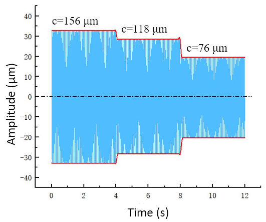
In this section, three groups of oil film clearance values are selected within this range, which are 156, 118 and 76 µm, respectively, and the initial value is 156 µm. Node 10 is taken as the measuring point to analyze the vibration of the rotor system at a speed of 1480 r min−1 based on the method of Wilson theta, as illustrated in Fig. 3. The vibration amplitude of the rotor system decreases with the decrease in the oil film clearance, leading to significant vibration reduction efficiency.
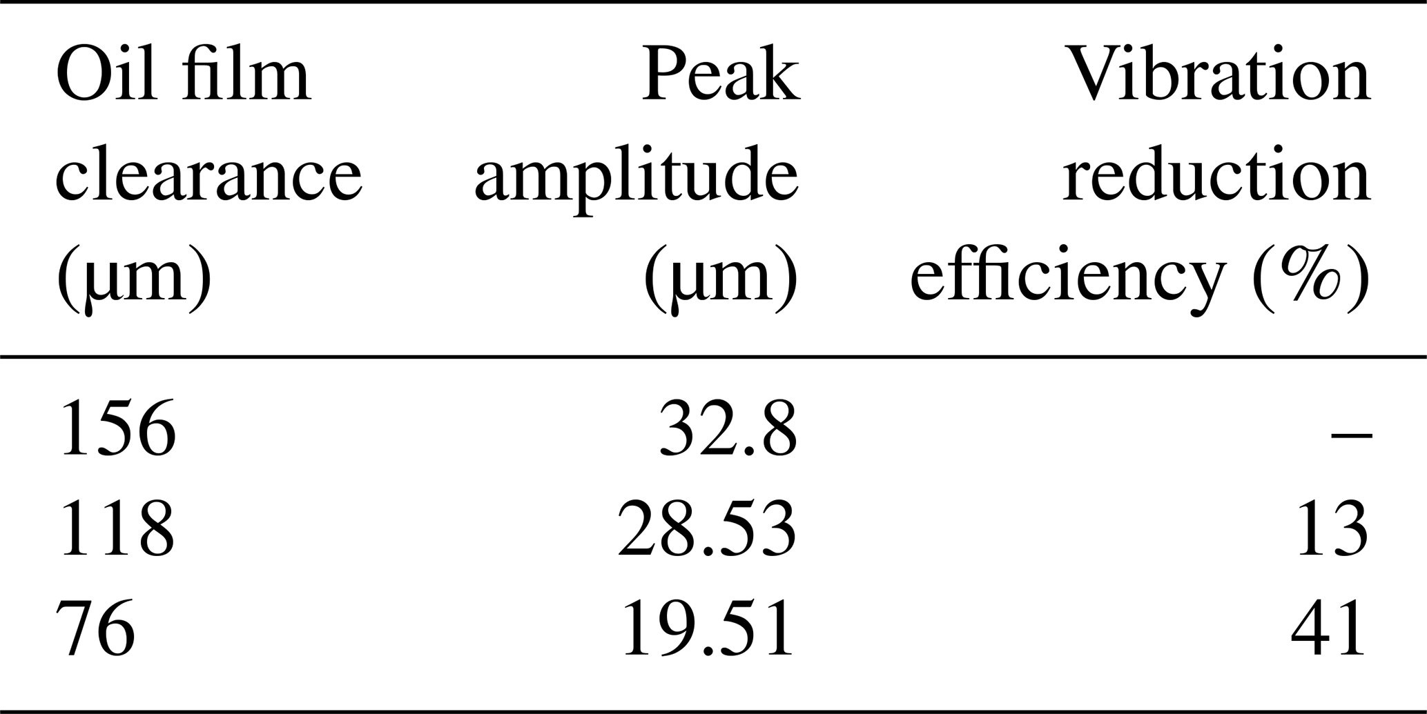
By comparing the vibration amplitude of the initial oil film clearance with one after adjusting the oil film clearance, the instant vibration reduction efficiency can be obtained. Table 1 shows the vibration reduction efficiency of the rotor system under different oil film clearance at a speed of 1480 r min−1. The SFD vibration reduction efficiency under different oil film clearance can be clearly seen from the table. As the oil film clearance decreases, the vibration amplitude of the rotor system decreases, and the SFD vibration reduction effect is better. When the oil film clearance decreases from 156 to 118 µm, the vibration response decreases by 13 %. When decreasing from 156 to 76 µm, the vibration response decreases by 41 %.
Table 1Vibration reduction efficiency under different oil film clearance.
4.1 Experimental system
Based on the vibration response analysis of the rotor system under the different oil film clearance above, a new type of SFD structure with a piezoelectric-driven split pad is innovatively designed, including a squirrel cage, bearing bush, piezoelectric ceramic actuator and shell. The structure is shown in Fig. 4.
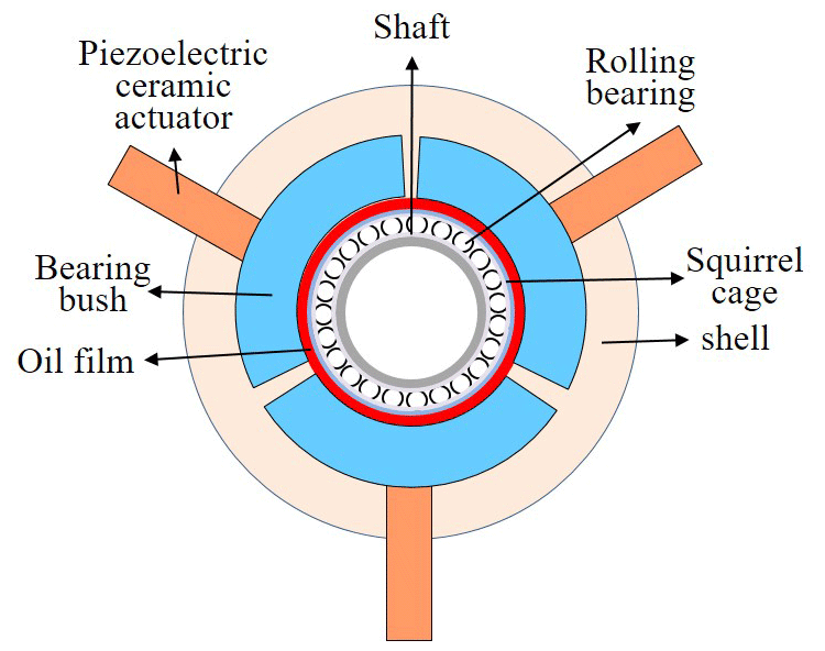
The new SFD is different from the traditional SFD structure. In order to adjust the oil film clearance, the movable split bearing bush is adopted. Oil film is formed between the bearing bush and the squirrel cage, and there is a clearance between the split pads to facilitate the movement of lubricating oil. Oil fills the entire area between the shell and the squirrel cage. A new type of SFD with a piezoelectric ceramic actuator drives the bearing bush to move, which can quickly adjust the oil film clearance and then control the vibration.
The piezoelectric ceramic actuator uses the VT14 model with a design of torque resistance by the COREMORROW company. It can effectively eliminate the torque generated by the external machinery and protect the ceramics from damage caused by direct action on the internal piezoelectric stack ceramics. Piezoelectric ceramic is a functional material that can convert electrical energy into displacement. Displacement output of the piezoelectric ceramic actuator is changed by applying different control voltages, and the bearing bush can be moved online and quickly without disassembling the main components of the rotor system (such as rotors and bearings). Thus, the oil film clearance can be changed to realize the vibration control of the rotor system. The piezoelectric ceramic actuator used in this paper is driven by 0–150 V voltage: the output displacement is 0–80 µm, the thrust reaches 1200 N and the time of response is short. The corresponding relation between driving voltage and displacement is shown in Fig. 5.
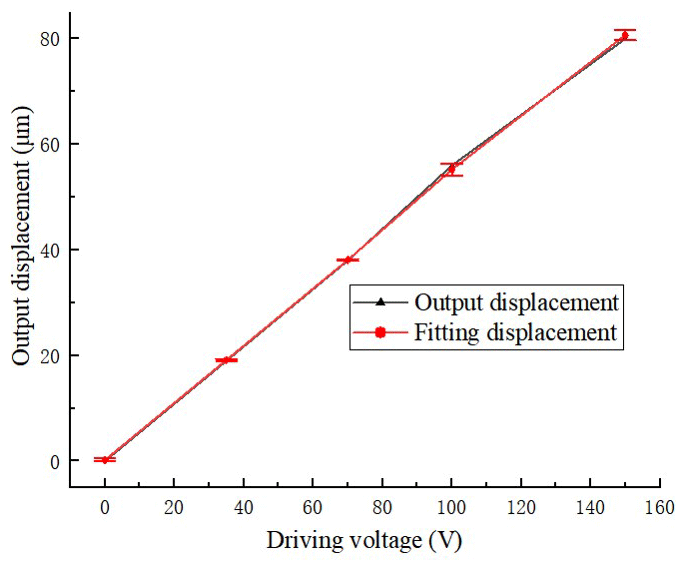
Through linear fitting, it is obtained that
where ΔL is the displacement of the piezoelectric ceramic actuator, and U is the voltage.
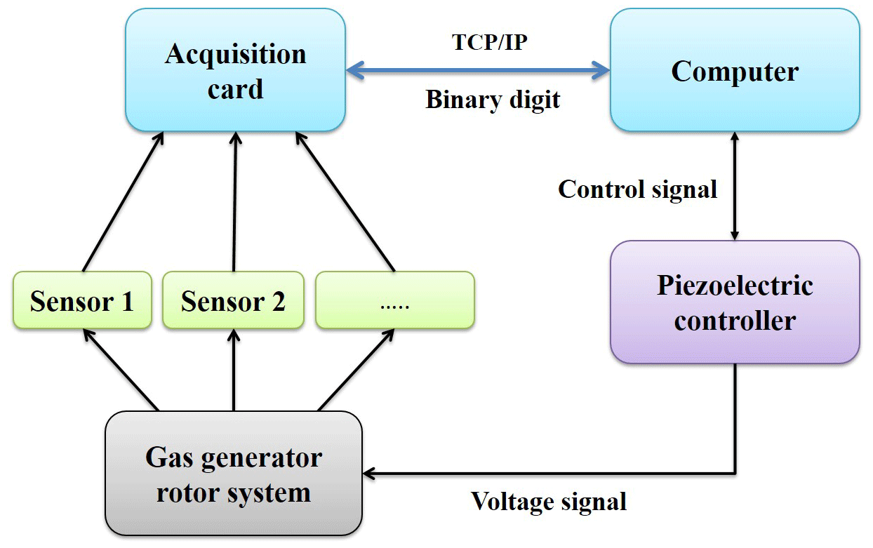
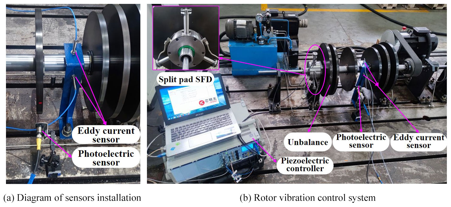
In order to control the vibration of the rotor system, an experiment system for vibration control of the gas generator rotor is built. The schematic diagram is shown in Fig. 6. The sensor monitors the rotational speed and vibration signals of the rotor system. The test signals are collected by the acquisition card, which communicates with the computer, and the computer displays and saves the data of the sensor. The computer communicates with the piezoelectric controller and sends the generated control signal to the piezoelectric controller, which makes the piezoelectric controller generate the driving voltage. The driving voltage drives the piezoelectric ceramic actuator to output displacement and pushes the bearing bush to move so as to change the oil film clearance. The rotor is powered by the motor and lubricated by the lubricating oil and oil pump. The elastic support system is composed of the front and rear supports. The signal acquisition system is composed of various sensors, an acquisition card and a computer. The executive components composed of a computer, a piezoelectric controller and a piezoelectric actuator regulate the driving voltage and the oil film clearance. The experimental system is shown in Fig. 7b. Because there is sufficient space between the centrifugal compressor disk and the three-stage axial-flow compressor disk to arrange eddy current sensors, the eddy current sensors are arranged radially at node 10. The photoelectric sensor is arranged next to the centrifugal compressor disk, and a light barrier is attached to the disk. The photoelectric sensor emits laser light. Every time the rotor rotates one revolution, the laser beam sweeps through the light barrier, causing the photoelectric sensor to generate a pulse to test the rotor speed. The specific layout of the sensors is shown in Fig. 7a. The changes in vibration amplitude under a different oil film clearance are analyzed by the simulation above. Based on the simulation analysis, the imbalance amount of 1.28 kg mm is set at the turbine disk. Three kinds of oil film clearances are selected for experimental research, which are 156, 118 and 76 µm, respectively. The initial oil film clearance is set at 156 µm, and the fixed speed is 1480 r min−1.
4.2 Experimental verification and result analysis
After adjusting the oil film clearance, the changes in the corresponding amplitude are shown in Fig. 8. The driving voltage of 0–4 s is 0 V, and the oil film clearance is 156 µm. The driving voltage of 4–8 s is 70 V, and the oil film clearance decreases from 156 to 118 µm. The specific response time changes are shown in Fig. 9. After changing the driving voltage, the vibration amplitude decreases and gradually reaches stability after 0.036 s. The driving voltage of 8–12 s is 150 V, and the oil film clearance is reduced to 76 µm. With the decrease in the oil film clearance, the vibration amplitude decreases gradually, and the vibration reduction effect becomes more and more significant.
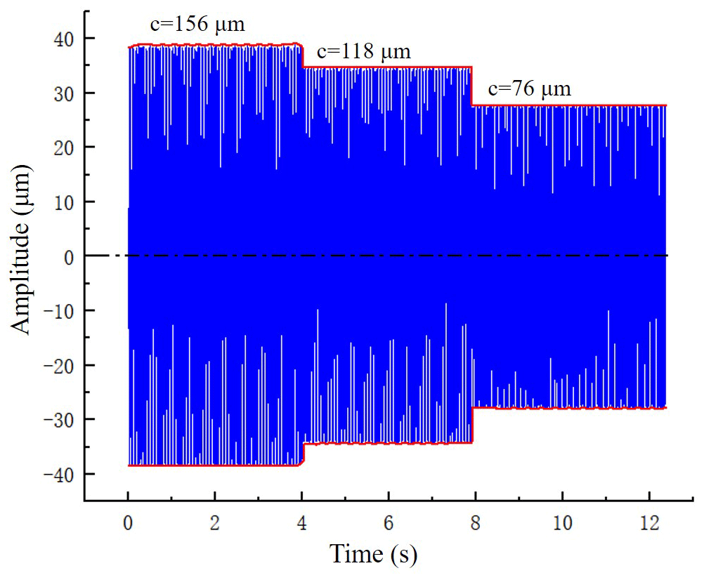
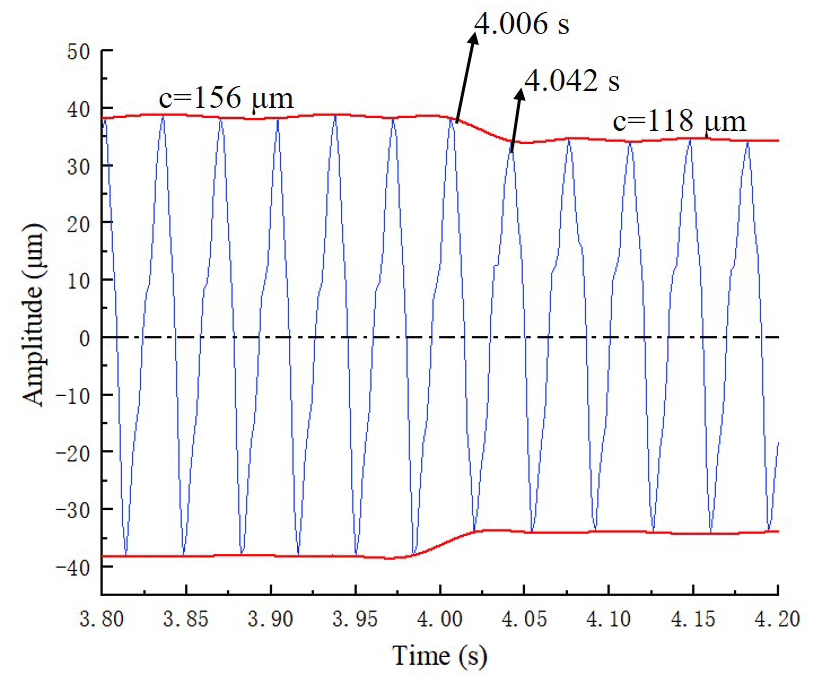
Table 2Vibration reduction efficiencies of different oil film clearances.
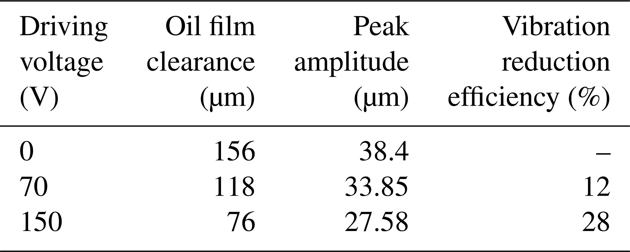
By adjusting the driving voltage and changing the oil film clearance, the consequent vibration amplitude reduction efficiency is shown in Table 3. When the oil film clearance is decreased from 156 to 118 µm, the vibration amplitude decreases by 12 %. When the oil film clearance is reduced to 76 µm, the vibration amplitude is reduced by 28 %.
This paper analyzes the relation between the oil film clearance of the damper and damping of a rotor system as well as the damping and vibration amplitude of the rotor system and deduces the functional relation between oil film clearance and amplitude. It can be concluded that, within a certain range, when oil film clearance increases, amplitude decreases. Taking the gas generator rotor system of a certain turboshaft engine as an example, the finite-element model of the gas generator rotor system with oil film bearing clearance is established to analyze the vibration response of the rotor system under different oil film clearance.
A new type of SFD structure driven by piezoelectric split pads was innovatively designed, and the vibration control system of the gas generator rotor was built to carry out the experimental research. The results show that the experiment and simulation trends are basically the same when the oil film clearance decreases from 156 to 118 µm. The vibration amplitude decreases and gradually reaches stability after 0.036 s, and the vibration amplitude of the rotor system decreases by 12 %. In addition, when the oil film clearance decreases from 156 to 76 µm, the vibration amplitude decreases by 28 %.
The new SFD adopts the piezoelectric-driven split-pad structure, which can adjust the oil film clearance online and quickly so as to control the vibration of the rotor system. The research results can provide a reference for vibration control methods of the engine rotor system. Meanwhile, it is difficult to accurately adjust the oil film clearance in the actual experiment due to machining and assembly errors of rotor system workpiece and hysteresis characteristics of the piezoelectric ceramic actuator. These reasons cause the experiment effect to be incompletely consistent with the simulation. In the future, we can achieve the ideal control effect by improving the machining, assembly and testing accuracy.
All the data used in this paper can be obtained by request from the corresponding author. All the figures were entirely created by the authors.
QL, CL, YZ and HF designed the new squeeze film damper. QL and GB proposed the research methods. QL, YZ and HF carried out the experiments. QL carried out simulation and experimental analysis. QL and HF adjusted the format of the manuscript.
The contact author has declared that none of the authors has any competing interests.
Publisher's note: Copernicus Publications remains neutral with regard to jurisdictional claims in published maps and institutional affiliations.
This project is supported by the National Natural Science Foundation of China (grant nos. 52175091 and 52075165), the Key R&D Plan of Hunan Province (grant no. 2022GK2023), the China Aerospace Development Independent Innovation Special Fund (grant no. KY-1003-2021-0019) and the Major Technical Research Project in Xiangtan (grant no. ZX-ZD2022100).
This paper was edited by Hui Ma and reviewed by two anonymous referees.
Bin, G., Huang, Y., Guo, S., Li, X., and Wang, G.: Investigation of Induced Unbalance Magnitude on Dynamic Characteristics of High-speed Turbocharger with Floating Ring Bearings, Chin. J. Mech. Eng., 31, 88, https://doi.org/10.1186/s10033-018-0287-5, 2018a.
Bin, G., Li, X., Shen, Y., and Wang, W.: Development of whole-machine high speed balance approach for turbomachinery shaft system with N+1 supports, Measurement, 122, 368–379, https://doi.org/10.1016/j.measurement.2018.02.035, 2018b.
Bin, G., Zhang, L., Yang, F., Chen, A.: The Influence of Ring-Speed Ratio Dynamic Change on Nonlinear Vibration Response of High-Speed Turbocharger Rotor System, Shock Vib., 2021, 9649232, https://doi.org/10.1155/2021/9649232, 2021.
Bin, G., Li, C., Li, J., and Chen, A.: Erosion-damage-induced vibration response of aero-gas generator rotor system, Mech. Syst. Signal Pr., 195, 110298, 0888–3270, https://doi.org/10.1016/j.ymssp.2023.110298, 2023.
Chasalevris, A. and Dohnal, F.: Vibration quenching in a large scale rotor-bearing system using journal bearings with variable geometry, J. Sound Vib., 333, 2087–2099, https://doi.org/10.1016/j.jsv.2013.11.034, 2014.
Chasalevris, A. and Dohnal, F.: A journal bearing with variable geometry for the suppression of vibrations in rotating shafts: Simulation, design, construction and experiment, Mech. Syst. Signal Pr., 52, 506–528, https://doi.org/10.1016/j.ymssp.2014.07.002, 2015.
Chen, D., Wang, H., Xie, Y., and Liang, D.: Regulating the vibration of aerostatic journal spindle based on piezoelectric ceramics, J. Manuf. Process., 85, 1526–6125, https://doi.org/10.1016/j.jmapro.2022.11.001, 2023.
Chen, K., Wang, W., Zhang, X., and Zhang, Y.: New step to improve the accuracy of blade tip timing method without once per revolution, Mech. Syst. Signal Pr., 134, 106321, https://doi.org/10.1016/j.ymssp.2019.106321, 2019.
Choy, K. C. and Halloran, J. D.: Application of hydrostatic SFDs, ASLE. Transactions., 25, 245–251, 1982.
Das, A. S., Nighil, M. C., Dutt, J. K., and Irretier, H.: Vibration control and stability analysis of rotor-shaft system with electromagnetic exciters, Mech. Mach. Theory, 43, 1295–1316, 2008.
Evstifeev, A., Kazarinov, N., Petrov, Y., Witek, L., and Bednarz, A.: Experimental and theoretical analysis of solid particle erosion of a steel compressor blade based on incubation time concept, Eng. Fail. Anal., 87, 15–21, https://doi.org/10.1016/j.engfailanal.2018.01.006, 2018.
Feulner, M., Liao, S., and Rose, B.: Ice Crystal Ingestion in a Turbofan Engine, SAE Technical Paper, 2015-01-2146, https://doi.org/10.4271/2015-01-2146, 2015.
Forte, P., Paternò, M., and Rustighi, E.: A magnetorheological fluid damper for rotor applications, Int. J. Rotat. Mach., 10, 175–182, https://doi.org/10.1080/10236210490426253, 2004.
Frankel, P. G., Withers, P. J., Preuss, M., Wang, H. T., Tong, J., and Rugg, D.: Residual stress fields after FOD impact on flat and aerofoil-shaped leading edges, Mech. Mater., 55, 130–45, https://doi.org/10.1016/j.mechmat.2012.08.007, 2012.
Fu, Zh., Shen, Y., Wang, S., Jiang, W., Li, J., Bin, G., and Hu B.: Asymmetric Bouc-Wen hysteresis modeling for MFC actuator via hybrid APSO-TRR identification algorithm, Sensor. Actuat. A-Phys., 346, 0924–4247, https://doi.org/10.1016/j.sna.2022.113830, 2022.
Hashemi, A., Jang, J., and Hosseini-Hashemi, S.: Smart Active Vibration Control System of a Rotary Structure Using Piezoelectric Materials, Sensors, 22, 5691, https://doi.org/10.3390/s22155691, 2022.
Horst, H. G. and Wölfel, H. P.: Active vibration control of a high speed rotor using PZT patches on the shaft surface, J. Intel. Mat. Syst. Str., 15, 721–728, https://doi.org/10.1177/1045389X04041938, 2004.
Jamshidi, R. and Jafari, A. A.: Nonlinear vibration of conical shell with a piezoelectric sensor patch and a piezoelectric actuator patch, J. Vib. Control, 28, 1502–1519, https://doi.org/10.1177/1077546321996922, 2021.
Jiang, L., Trembath, P., Patnaik, P., and Capurro, M.: Environmental particle rebound/deposition modeling in engine hot sections, Front. Mechan. Eng., 86106, V10BT31A005, https://doi.org/10.3389/fmech.2022.924755, 2023.
Li, C., She, H., Tang, Q., and Wen, B.: The coupling vibration characteristics of a flexible shaft-disk-blades system with mistuned features, Appl. Math. Modell., 67, 557–72, https://doi.org/10.1016/j.apm.2018.09.041, 2019.
Li, C., Bin, G., Li, J., and Liu, Z.: Study on the erosive wear of the gas-solid flow of compressor blade in an aero-turboshaft engine based on the Finnie model, Tribol. Int., 163, 107197, https://doi.org/10.1016/j.triboint.2021.107197, 2021.
Li, C., Bin, G., Li, J., and Yang, P.: Erosion wear characteristics of the aero-compressor blades in full speed range, Powder Technol., 418, 118227, https://doi.org/10.1016/j.powtec.2023.118227, 2023.
Lu, K., He, L., Zhang, Y., Chen, Z., and Yan, W.: Experimental study on vibration suppression of gear shaft misalign-ment with ISFD, High Technol. Lett., 25, 17–27, https://doi.org/10.1155/2017/7246356, 2019.
Ma, H., Li, H., Niu, H., Song, R., and Wen, B.: Nonlinear dynamic analysis of a rotor-bearing -seal system under two loading conditions, J. Sound Vib., 332, 6128–6154, https://doi.org/10.1016/j.jsv.2013.05.014, 2013a.
Ma, H., Li, H., Zhao, X., Niu, H., and Wen, B.: Effects of eccentric phase difference between two discs on oil-film instability in a rotor-bearing system, Mech. Syst. Signal Pr., 41, 526–545, https://doi.org/10.1016/j.ymssp.2013.05.006, 2013b.
Ma, H., Li, H., Niu, H., Song, R., and Wen, B.: Numerical and experimental analysis of the first and second-mode instability in a rotor-bearing system, Arch. Appl. Mech., 84, 519–541, https://doi.org/10.1007/s00419-013-0815-9, 2014.
Ma, X., MA, H., Qin, H., Guo, X., Zhao, C., and Yu, M.: Nonlinear vibration response characteristics of a dual-rotor-bearing system with squeeze film damper, Chin. J. Aeronaut., 34, 128–147, https://doi.org/10.1016/j.cja.2021.01.013, 2021.
Malgaca, L., AI-Qahtani, H., and Sunar, M.: Vibration control of rotating blades using root-embedded piezoelectric materials, Arab. J. Sci. Eng., 40, 1487–1495, https://doi.org/10.1007/s13369-014-1566-9, 2015.
Mohammadi, B. and Khoddami, A. S.: Representative volume element-based simulation of multiple solid particles erosion of a compressor blade considering temperature effect, P. I. Mech. Eng. J-J.-Eng., 234, 1173–1184, https://doi.org/10.1177/1350650119884825, 2020.
Mu, C., Darling, J., and Burrows, C. R.: An appraisal of a proposed active squeeze film damper, J. Tribol., 113, 750–754, https://doi.org/10.1115/1.2920688, 1991.
Nicholas, T.: High cycle fatigue: a mechanics of materials perspective, Washington DC – Elsevier Science and Technology, 656, 2006.
Palazzolo, A. B., Lin, R. R., Alexander, R. M., Kascak, A. F., and Montague, J.: Piezoelectric pushers for active vibration control of rotating machinery, J. Vib. Acoust., 111, 298–305, https://doi.org/10.1115/1.3269856, 1989.
Pan, Y., Liu, R., Bin, G., and He, X.: Vibration and noise reduction of phononic crystal structure laid on the noise transmission path of axial piston pump, Appl. Acoust., 200, 109075, 0003–682X, https://doi.org/10.1016/j.apacoust.2022.109075, 2022.
Piccirillo, V., Balthazar, J. M., and Tusset, A. M.: Chaos control and impact suppression in rotor-bearing system using magnetorheological fluid, The Eur. Phys. J. Special Top., 224, 3023–3040, https://doi.org/10.1140/epjst/e2015-02604-7, 2015.
Pinte, G., Devos, S., Stallaert, B., Symens, W., Swevers, J., and Sas, P.: A piezo-based bearing for the active structural acoustic control of rotating machinery, J. Sound Vib., 329, 1235–1253, https://doi.org/10.1016/j.jsv.2009.10.036, 2010.
Pritchard, J. I. and Adelman, H. M.: Optimal placement of tuning masses for vibration reduction in helicopter rotor blades, AIAA J., 28, 309–315, https://doi.org/10.2514/3.10390, 1990.
Rossi, A., Botta, F., Giovannelli, A., and Belfiore, N, P.: A novel approach to reduce fan rotor blades stress in case of resonance due to inlet flow distortion by means of piezoelectric actuators, J. Sound Vib., 548, 117552, 0022-460X, https://doi.org/10.1016/j.jsv.2023.117552, 2023.
Santos, I. F. and Ncoletti. R.: Influence of Orifice Distribution on the Thermal and Static Properties of Hybridly Lubricat-ed Bearings, Int. J. Solids Struct., 38, 2069–2081, https://doi.org/10.1016/S0020-7683(00)00153-0, 2001.
She, H., Li, C., Tang, Q., and Wen, B.: The investigation of the coupled vibration in a flexible-disk blades system considering the influence of shaft bending vibration, Mech. Syst. Signal Pr., 111, 545–569, https://doi.org/10.1016/j.ymssp.2018.03.044, 2018.
Shi, H., Song, Z., Bai, X., Hu, Y., Li, T., and Zhang, K.: A novel digital twin model for dynamical updating and real-time mapping of local defect extension in rolling bearings, Mech. Syst. Signal Pr., 193, 110255, 0888–3270, https://doi.org/10.1016/j.ymssp.2023.110255, 2023a.
Shi, H., Li, R., Bai, X., Zhang, Y., Min, L., Wang, D., Lu, X., Yan, Y., and Lei, Y.: A review for control theory and condition monitoring on construction robots, J. Field Robot., 40, 934–954, https://doi.org/10.1002/rob.22156, 2023b.
Singh, K., Sharma, S., Kumar, R., and Talha, M.: Vibration control of cantilever beam using poling tuned piezoelectric actuator, Mech. Based Des. Struc., 51, 2217–2240, https://doi.org/10.1080/15397734.2021.1891934, 2021.
Sinha, S. K., Turner, K. E., and Jain, N.: Dynamic loading on tubofan blades due to bird-strike, J. Eng. Gas Turb. Power, 133, 122504-1-13, https://doi.org/10.1115/1.4004126, 2011.
Sivrioglu, S.: Adaptive control of nonlinear zero-bias current magnetic bearing system, Nonlinear Dynam., 48, 175–184, https://doi.org/10.1007/s11071-006-9081-5, 2007.
Wang, J., Zhang, J., Ma, L., and Yu, Y.: Study on the effect mechanism of MRD to rotor system, Appl. Sci., 9, 2247, https://doi.org/10.3390/app9112247, 2019.
Wang, L., Bin, G., Li, X., and Zhang, X.: Effects of floating ring bearing manufacturing tolerance clearances on the dynamic characteristics for turbocharger, Chin. J. Mech. Eng., 28, 530–538, https://doi.org/10.3901/cjme.2015.0319.034, 2015.
Wang, L., Bin, G., Li, X., and Liu, D.: Effects of Unbalance Location on Dynamic Characteristics of High-speed Gasoline Engine Turbocharger with Floating Ring Bearings, Chin. J. Mech. Eng., 29, 271–280, https://doi.org/10.3901/cjme.2015.1013.121, 2016.
Wang, W., Hu, D., Li, Q., and Zhang, X.: An improved non-contact dynamic stress measurement method for turbomachinery rotating blades based on fundamental mistuning model, Mech. Syst. Signal Pr., 144, 106851, https://doi.org/10.1016/j.ymssp.2020.106851, 2020.
Yang, P., Yue, W., Li, J., Bin, G., and Li, C.: Review of damage mechanism and protection of aero-engine blades based on impact properties, Eng. Fail. Anal., 140, 106570, https://doi.org/10.1016/j.engfailanal.2022.106570, 2022.
Yang, Y., Wu, Q., Wang, Y., Qin, W., and Lu, K.: Dynamic characteristics of cracked uncertain hollow-shaft, Mech. Syst. Signal Pr., 2019, 124, 36–48, doi:10.1016/j.ymssp.2019.01.035, 2019.
Zhang, X., Wang, W., Chen, K., Li, W., Zhang, D., and Tian, L.: Five dimensional movement measurement method for rotating blade based on blade tip timing measuring point position tracking, Mech. Syst. Signal Pr., 161, 107898, https://doi.org/10.1016/j.ymssp.2021.107898, 2021.
Zhang, X., Yang, Y., Ma, H., Shi, M., and Wang, P.: A novel diagnosis indicator for rub-impact of rotor system via energy method, Mech. Syst. Signal Pr., 185, 10825. https://doi.org/10.1016/j.ymssp.2022.109825, 2023.
Zhao, Z., Liu, L., Chen, W., and Luo, G.: Numerical simulation methodology of multi-layer Kevlar 49 woven fabrics in aircraft engine containment application, Int. J. Crashworthiness., 24, 86–99, https://doi.org/10.1080/13588265.2017.1422374, 2019.
Zhong, X., Huang, Y., Bin, G., and Chen, A.: Effect of the inlet oil temperature on vibration characteristics of the high-speed turbocharger rotor system, P. IMechE Part J: J. Eng. Tribol., 235, 2086–2098, https://doi.org/10.1177/1350650120987033, 2021.
Zhu, C.: Dynamics of a rotor supported on magnet-rheological fluid SFD, Chin. J. Aeronau., 14, 6–12, 2001.
- Abstract
- Introduction
- SFD principle analysis
- Analysis of the influence of oil film clearance on the vibration of a rotor system
- Experiment on the vibration control of a rotor system
- Conclusions
- Data availability
- Author contributions
- Competing interests
- Disclaimer
- Financial support
- Review statement
- References