the Creative Commons Attribution 4.0 License.
the Creative Commons Attribution 4.0 License.
 | 17 Nov 2022
Research on structural parameters and kinematic properties of a drill-in granary grain condition detector
Qiang Yin
Junpeng Yu
Shaoyun Song
Yonglin Zhang
Gang Zhao
Zhiqiang Hao
In order to realize the real-time monitoring of the grain condition, grain condition information should be collected during storage operations. A drill-in granary grain condition detector which can drill into a grain pile in a granary is proposed. The kinematic models of four Archimedes screw mechanisms were established, and the motion characteristics of grain particles in spiral grooves were described. Several groups of single variable simulation experiments are designed to discuss the important factors affecting the motion performance of the detector. Based on a discrete element method with multi-body dynamics (DEM-MBD) simulation calculation, the force and velocity change images of grain particles were obtained to verify the feasibility of the scheme. The steering function of the detector is verified by simulation, and the relationship between the steering radius and the screw rotation speed difference is analyzed. The results show that the drill-in granary grain condition detector can move forward and turn when it is immersed in the grain pile. It has the characteristics of excellent flexibility and a high degree of freedom. It compensates for the current situation in which robots cannot go deep inside the grain pile and complete the steering.
- Article
(23924 KB) - Full-text XML
- BibTeX
- EndNote


In the grain storage industry, it is critical to monitor real-time information about the grain storage conditions and grain quality. In view of the current monitoring methods of grain storage information, this paper presents a kind of drill-in granary grain condition detector. It is equipped with temperature, CO2, and humidity sensors. It can obtain the information of the grain condition by entering the grain pile. It solves the inconvenience caused by the current granary layout sensor. In the case of insufficient granary automation, its research is particularly important.
This paper mainly studies the kinematic analysis of the drill-in granary grain condition detector after it enters grain pile. The drill-in granary grain condition detector can complete the walking movement in the grain pile. It is mainly composed of four independent Archimedes screws evenly distributed around the shell, and the middle also has the Archimedes spiral mechanism. They are connected together by an oval shell and belong to a screw propulsion vehicle. It is powered by the rotation of the screws that are evenly distributed around the shell. It completes the forward movement and the steering movement in the heap through the coordination of the screw. With the middle Archimedes spiral mechanism and the inner wall of the shell, a screw transport mechanism is formed to complete the backward transport of grain to reduce movement resistance. Using the screw mechanism has the advantage of walking on a soft road, and sensors can be mounted on the spiral propulsion mechanism to detect the temperature, humidity, and carbon dioxide in each position of the granary, so as to realize the monitoring of the grain situation.
The innovation of the drill-in granary grain condition detector lies in a new screw propulsion vehicle model. It consists of a shell as the main body, four axes parallel to each screw, and the middle of the screw transport mechanism. Its four screws and the middle of the screw transport mechanism are independent of each other, respectively, and are driven by their respective motors. The axes of its four screws are parallel to each other. The spiral of two adjacent screws are in opposite directions. This design makes it stable and flexible in motion. It can complete the forward movement along the axis of the shell in the three-dimensional space of the grain stack and can complete the multi-directional steering movement in the case of drilling into the grain stack. It can inspect every sampling point in the granary. Unlike a traditional robot that moves on a grain surface, it has fewer restrictions on its movement in space. It has the advantages of dexterity, a high degree of freedom, and strong adaptability.
The structure of this article is as follows. Section 2 introduces the research significance and related background of the drill-in granary grain condition detector and extends the purpose of this research. Section 3 introduces the overall design of the drill-in granary grain condition detector and the working principle of key components and is illustrated in the figures. Section 4 continues the theoretical calculation analysis of the key technology in this design. The kinematic analysis of the screw in the discrete environment in the granary is completed, and the steering kinematic analysis of the device is carried out. The influence of different parameters of the key components on the overall motion state of the device is discussed. Based on a discrete element method with multi-body dynamics (DEM-MBD) simulation analysis, the whole device was taken as the analysis object to solve the kinematics image in the three-dimensional space of the granary. The kinematics law of the whole device under the influence of different factors is obtained. Section 5 is the conclusion.
Grain condition monitoring is of great significance to the grain storage industry. Surveys show that most developing countries in the world lose between 20 % and 40 % of their crops in legumes and cereals after harvest (Brown et al., 2013; Magan and Aldred, 2007; Manandhar et al., 2018; Olorunfemi and Kayode, 2021). The quantity of loss during storage accounted for about 55 % of the total loss (Banga et al., 2018; Gitonga et al., 2013; Kumar and Kalita, 2017; Liu et al., 2017). In grain storage, grain mildew and insect pests are important reasons for grain quality decline, which not only cause a lot of economic losses but also have an impact on national food security (Feinstein, 1969; Abramson et al., 2005; Duan et al., 2019; Ramachandran, 2022).
The higher temperature and moisture content of the grain can provide favorable conditions for mildew, insect pests, and heat from the grain itself. In turn, mildew, heat, and insect infestation of grain can change the concentration of CO2, humidity, and temperature inside the grain stacks (Maier et al., 2010; Mannaa and Kim, 2018; Schmidt et al., 2016; Ziegler et al., 2021). Therefore, these physical and chemical parameters will be used to control and monitor the quality of grain. At present, temperature sensors, humidity sensors, and CO2 concentration sensors are commonly used for grain situation monitoring in granaries. Thermocouple and integrated silicon (digital) sensors are the most commonly used temperature sensors for grain storage in the market (Lu, 2011; Neethirajan et al., 2008; Wang et al., 2013). Thermocouple and digital temperature sensors are made of cables for warehouse installation and can be used for grain temperature monitoring. As grain is a poor heat conductor, a large number of temperature sensors are needed to be evenly and reasonably arranged in the granary. Different from humidity sensors and CO2 concentration sensors, only a small number of temperature sensors can complete the corresponding information collection. The reason is that air circulates through the grain stacks (Gonzales et al., 2009; Neethirajan et al., 2010; Singh and Fielke, 2017).
When using the layered arrangement of multiple sensors (Onibonoje et al., 2019; Qi and Li, 2012; Wu et al., 2021; Yu et al., 2011), it is sufficient to use the cylinder used in household granaries or transportation, but it will have many shortcomings if it is used in large warehouse. In developing countries, the automation degree of large granaries is low, and the technology of grain information collection systems is backward, which makes it is difficult to meet the requirements of storage enterprises (Deichmann et al., 2016; Henny and Stamm, 1981; Lutful et al., 2013). Rather than systematically replacing or modifying the monitoring and control system, the addition of automated equipment in the warehouse makes it more acceptable for storage enterprises. The low degree of automation of grain in and out of large warehouse also hinders the hierarchical arrangement of sensors in the grain situation monitoring system (Newman, 1987) because the distribution of sensors may interfere in the in-and-out movement of grain. The drill-in granary grain condition detector can supplement the deficiency of modern grain condition monitoring and control systems. It is equipped with a corresponding sensor with high flexibility and a high degree of freedom characteristics and can accurately obtain the grain situation information of each position in the granary. It can be recycled after performing the task of detecting the grain condition, thereby avoiding conflict and interference with other granary operations. Therefore, the drill-in granary grain condition detector is of great significance for grain condition monitoring and control.
In order to meet the application requirements of the drill-in granary grain condition detector, it has become a prerequisite to develop the walking device in a grain pile with the performance meeting the requirements. It not only meets the needs of modern grain situation monitoring but also the national conditions of developing countries aiming to reduce transformation costs. Some scholars or scientific research institutions have carried out research on the walking mechanism in a granary or in other discrete material environment, which can provide us with some new ideas.
Safar et al. (2019) designed a helical wheel-type omnidirectional mobile walking mechanism. It is composed of four spiral wheels with axes in the same plane. The direction of each spiral wheel is adjusted by a separate steering gear, which has certain flexibility and different traction performance on different surfaces and in different wheel directions. The screw-driven rover on soft terrain was studied by Nagaoka et al. (2010b). A new double Archimedes rod-driven rover was introduced. Based on the mathematical modeling of the Archimedes rod-driven mechanism walking on soil, a three-dimensional kinematic model and a dynamic model were established, which were verified by simulation analysis. The maneuverability was also studied. The motion trajectory was empirically analyzed by independently inputting different screw angular velocities (Nagaoka et al., 2010a). Green et al. (2021) developed a new spiral-propelled digging rover called Casper. Casper is mainly composed of four Archimedes screws. The two screws in the front can be used as a moving mechanism and can also be used to loosen discrete particles. It facilitates the rear ramp mechanism to shovel into the collection bin. The influence of different factors on mining speed, power consumption, and speed are mainly studied. Thoesen et al. (2020, 2018) and Eimanis and Auzins (2019) studied the changes in thrust generated by helical propulsion mechanism at different pitch and speed in granular media through experiments and simulation calculations and further proposed the feasibility of helical drive vehicle moving in discrete environment, which was verified by a DEM-MBD simulation. Darbois Texier et al. (2017) studied the relationship between the dynamics of helical mechanisms in granular media and the spiral speed and its geometric parameters. Li et al. (2021) proposed a method to study the motion characteristics of flexible plates in granular media. The specific structure of its model was a two-fin robot, and a flexible fin with an origami structure was proposed to improve its compliance in particle motion. Based on granular resistive force theory (RTF), the characteristics of motion, deformation, and propulsion force of the two-fin robot were analyzed. Pan et al. (2021) studied the motion and force of spherical objects intruding into granular media and proposed the concepts of dynamic buoyancy of particles and the Saffman lift of particles.
The above research provides many new ideas for the research of the drill-in granary grain condition detector, but many of the existing screw-propelled vehicles (SPVs) are applied to the surface of granular medium stacks. It cannot meet the needs of information detection in granaries. The research of other flexible structure walking mechanisms is still in the initial stages of theory, and it will take a long time to apply it to grain information detection.
To sum up, it is necessary to monitor the grain situation of large warehouse, and the research of the drill-in granary grain condition detector is one of the ways to solve the difficulty of monitoring information of a large warehouse. At present, the research of the SPVs in a discrete environment provides a theoretical basis for the drill-in granary grain condition detector.
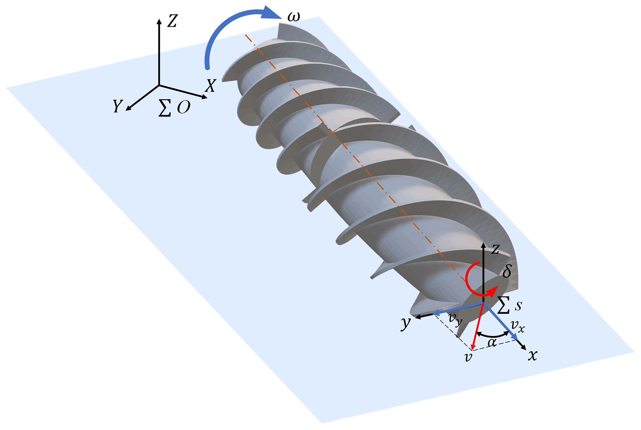
The main grains stored in granaries are wheat, rice, soybeans, and corn, and the bulk grains are stored in a large warehouse. The screw drive is one of the most efficient ways to drive on such a soft surface composed of particulate matter (Knight et al., 1965). When the two axes are parallel to each other and in the same plane, then the screw can drive the vehicle to complete forward, backward, and turning movements on the surface of the grain pile. The opposite direction of the two screws is conducive to the overall torque balance when the vehicle is running. It is also feasible to design four screws to drive the vehicle to complete the movement and steering in the three-dimensional working space inside the grain pile. If the vehicle can complete the movement in the grain pile, then it can try to carry sensors to detect the grain situation. Figure 1 shows the movement mode of the drill-in granary grain condition detector (hereinafter referred to as a detector) in the granary after it is inserted into the grain pile.
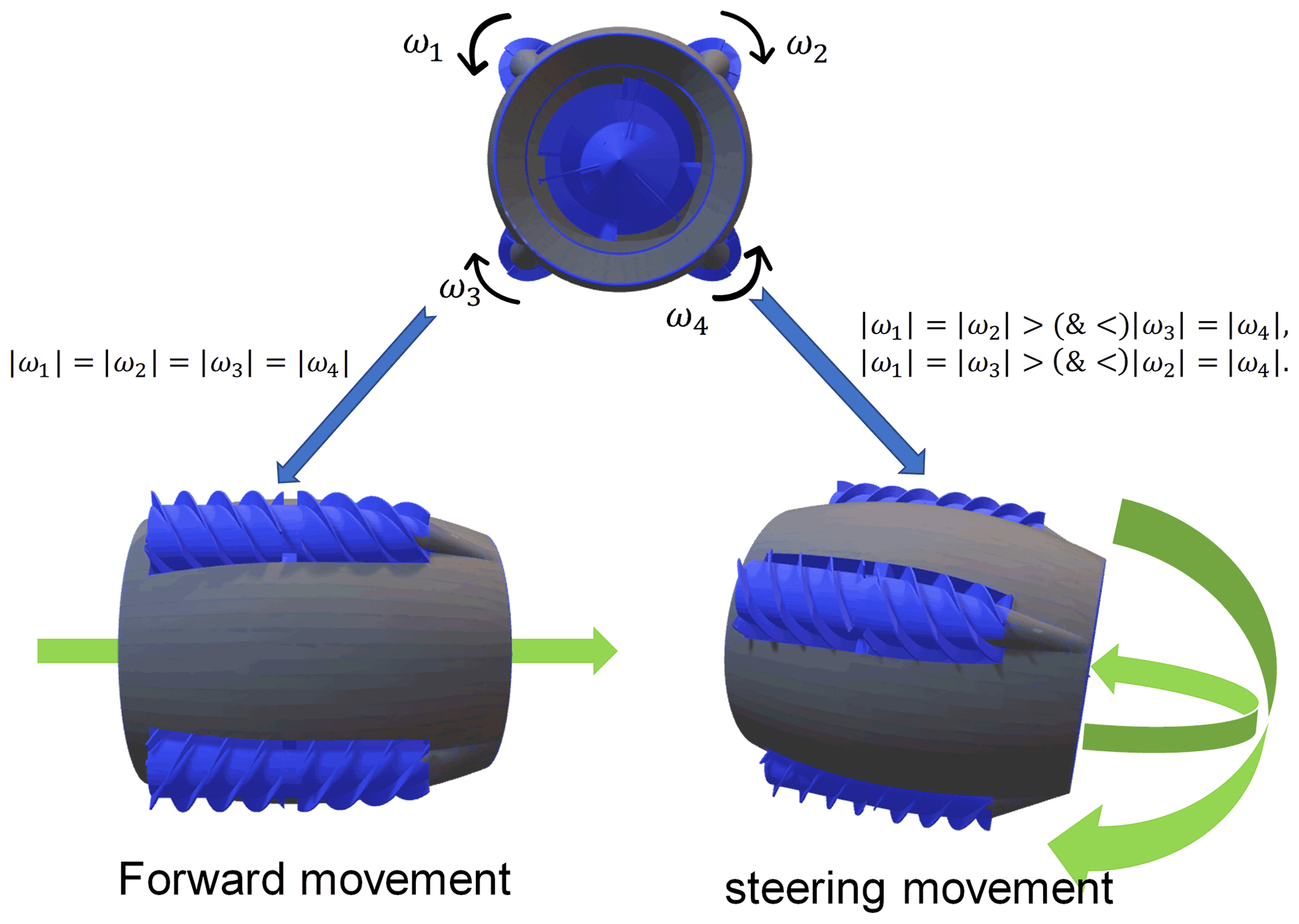
The detector works by going deep into a pile of grain and being propelled by four screws that rotate at the same speed. The four screws rotate in the same direction as the spiral. The four screw axes of the detector are parallel to each other, and the spiral directions of the two adjacent screws are different. The differential steering of the detector in the grain pile is realized by using the rotational speed difference in two pairs of the screws. A screw transport drum at the center of the detector delivers grain to the rear of the detector to reduce forward resistance and to rotate in the same direction as its screw. It has four spiral blades that form enclosed spaces with the inner shell. It is conducive to improving the transport efficiency and motion stability. The whole device has a total of five rotational pairs, and each rotational pair of the transmission system is independent of each other. Each spiral mechanism is driven by a motor to make the whole more flexible, and the direction of rotation of each spiral mechanism is always consistent with its spiral direction. The shape of the detector shell is similar to an oval shape, which facilitates steering. Its overall structure and internal transmission diagram are shown in Fig. 2.
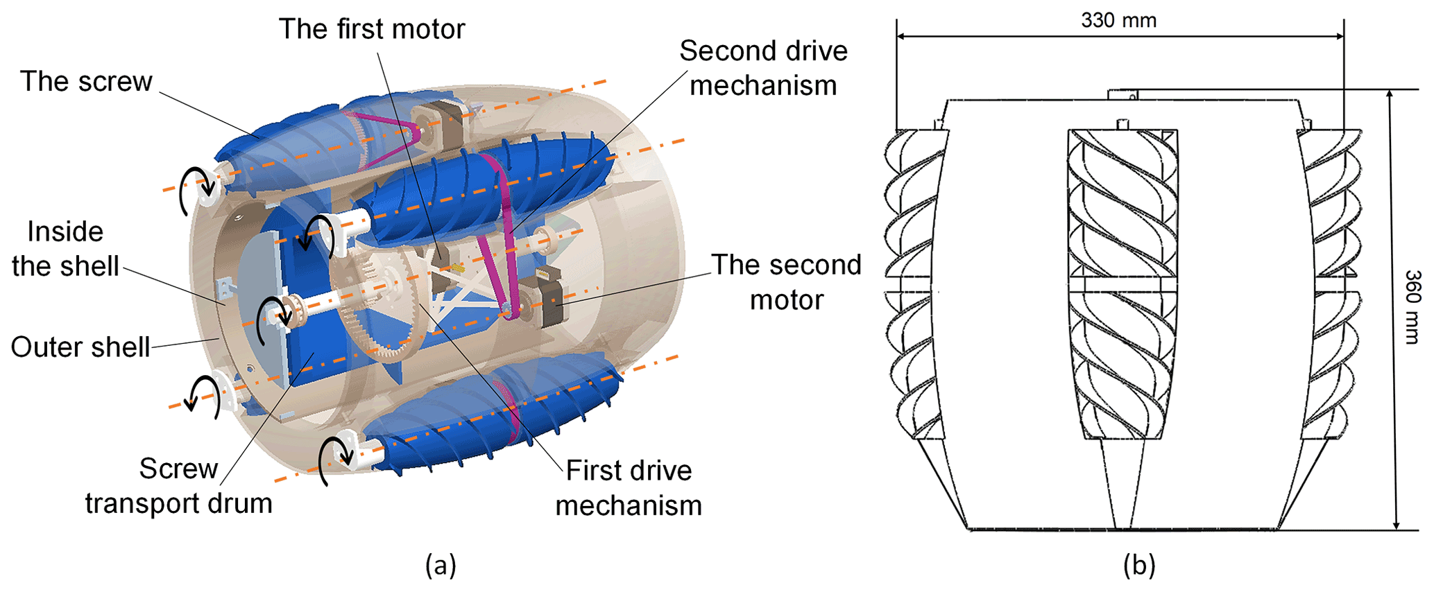
Figure 2Schematic diagram of the drill-in granary grain condition detector. (a) Internal drive structure. (b) Approximate geometric dimension.
3.1 Geometric parameters of the screw
The screw is the core component that drives the motion of the detector. It is composed of two shapes of the screw, where one is composed of a cylindrical drum and spiral blade, and the other is composed of an olive-shaped drum and spiral blade. The olive-shaped drum is located at the front of the screw. It reduces the resistance of the detector when it moves forward and turns. Helical blades have a certain height to provide adequate traction and can be designed to be single or multiple. The structure of a single screw is shown in Fig. 3.
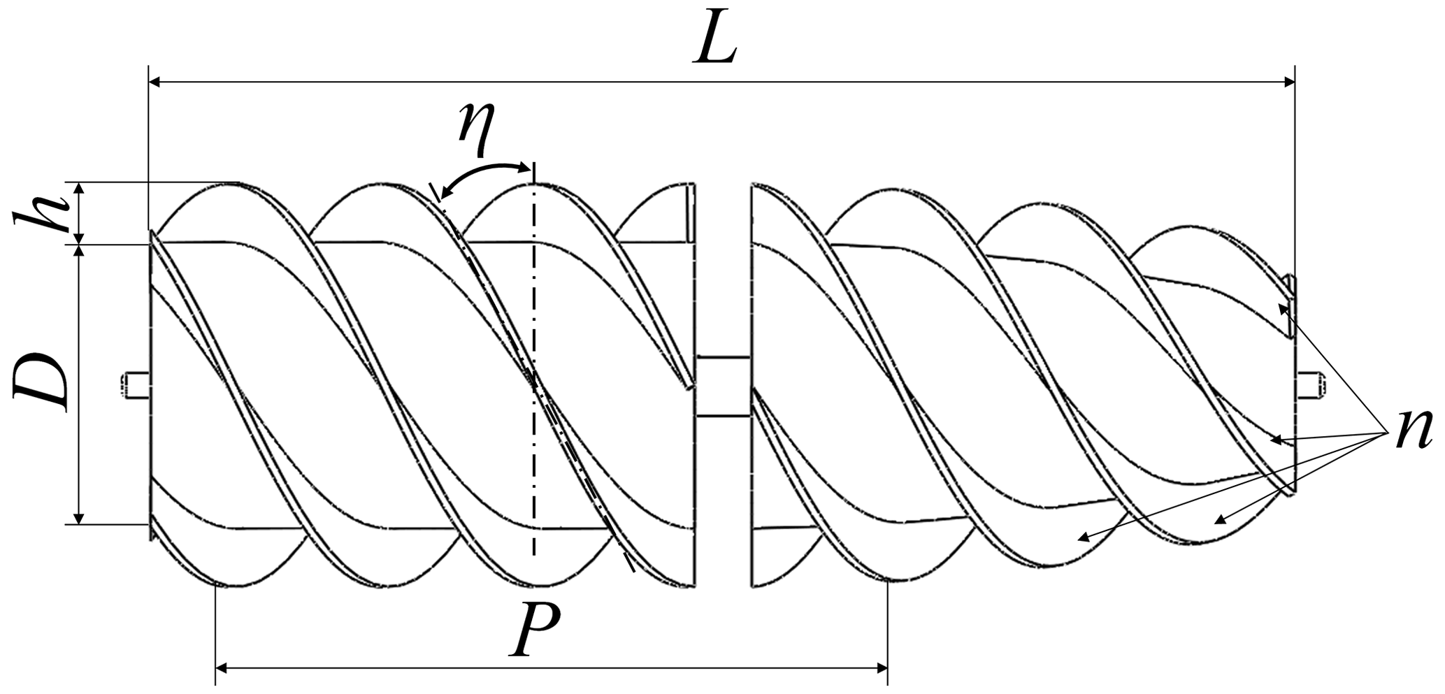
When the detector moves inside the grain pile, the spiral blade can segment the grain. The higher the spiral blade, the thicker the grain layer cut, and the greater the torque required by the screw will be. The ratio of the spiral blade height to drum diameter is α, as follows:
where D is the diameter of the screw drum, and h is the height of the spiral blade. When the α value is close to 0.125, the driving performance of the mechanism is better than that of the α value 0.167 and 0.208 (Neumeyer and Jones, 1965). Considering that the detector will need a greater propulsion force to overcome the resistance after entering the grain pile, α=0.214, which is greater than 0.125.
The expression of the relation between the helix angle and pitch on the drum is as follows:
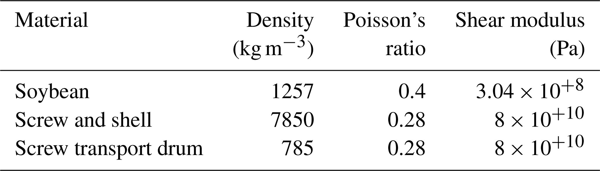
where P is the pitch, h is the height of the spiral blade, η is the helix angle, and r is the radius of the drum. According to Cole and Sch's (1961) research, the helix angle with the best energy-saving effect and performance is 30∘. Since the mechanism is embedded in the grain pile, the value of η is 30∘, considering the propulsion rate of the detector. To sum up, the key parameters of the screw are shown in Table 1.

3.2 Screw transport drum
The main structure of the screw transport drum is also composed of a hollow drum and spiral blade, and its structural design is shown in Fig. 4.
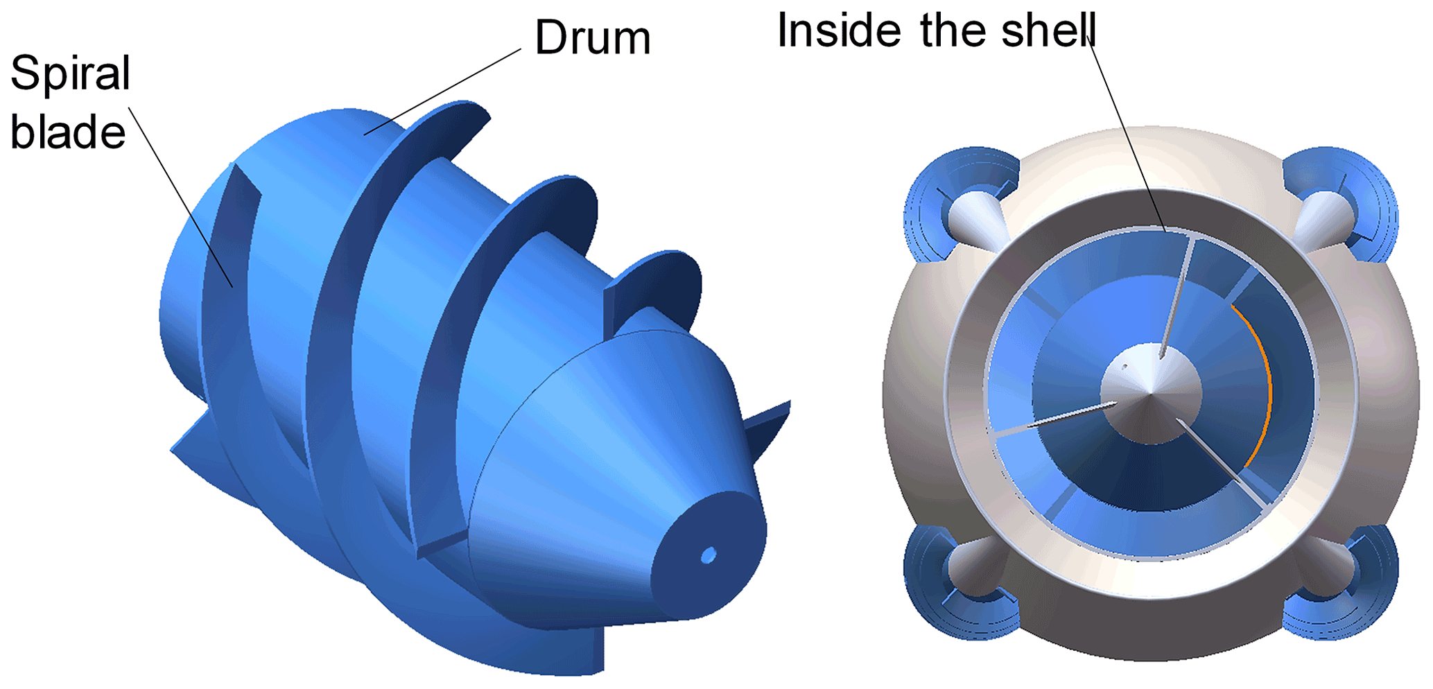
The hollow internal structure of the screw transport drum can accommodate the battery, motor, and internal meshing gear mechanism. The whole drum runs through an axis part. Its two ends are connected by bearings, and the rotation of the spiral transport mechanism is realized by an internal meshing gear transmission. It is also designed with four spirals to maintain the high efficiency of the transport. The height of the spiral blade is almost close to the inner shell, which forms a closed space for the grain and improves the transportation efficiency of the grain. After the detector moves deep into the grain pile, the screw transport drum keeps rotating. It transports incoming grain to the rear of the detector by means of a screw transport, thus reducing the drag of the detector's propulsion.
3.3 Analysis on model to maneuvers
As shown in Fig. 1, the motion states of the detector include moving forward and steering along the axis of the overall mechanism. The maintenance and transformation of the two motion states are coordinated by the rotation of four screws. Each screw receives a different axial force and lateral force at different speeds. The different rotation difference between the screws makes the whole mechanism have different force conditions. As shown in Fig. 5, the two screws in each view are a group. When the four screws rotate at an equal rotation speed, they receive the same magnitude and direction of the axial force. The lateral force is equal and opposite in magnitude, so the detector keeps steady progress. When , the traction force of the two groups of the screws is not the same. The traction relationship is , and the detector will turn around the y axis in the negative direction of the z axis. When , the traction relationship is . The mechanism will be turned about the y axis in the positive direction of the z axis. When , the traction force of the two groups of the screws is not the same. The traction relationship is , an the detector will be turned in the positive direction of the y axis around the z axis. When , the traction relationship is . The detector will then turn around the z axis in the negative direction of the y axis.

Figure 5Relationship between screw speed and driving direction of the mechanism. Note: ω1 is the rotational speed of the right-hand screw, ω2 is the rotational speed of the left-hand screw, ω3 is the rotational speed of left-hand screw, and ω4 is the rotational speed of right-handed screw. The rotational speed of the screw is the same as the direction of the screw. Fx is the axial force on the screw, and Fy and Fz are the lateral forces on the screw.
The blades of the screw transport drum located in the middle of the detector form a closed space with the inner shell (for grain size). Its screw transport drum is limited to transferring grain in front of the detector. Its screw transport drum does not exert an obvious force influence on the change in the direction of motion of the detector. In order to achieve no rotation around the x axis when the detector moves, the two adjacent screw rods are designed with different spiral directions. The lateral force of each screw rod is offset with each other. Each screw is subjected to the lateral forces in the z and y directions of Fz and Fy, respectively. Assuming that the straight-line distance of the screw axis and x axis is lsx, the relationship between the overall torque M and Fz and Fy of the detector on plane yoz can be expressed as follows:
4.1 Kinematics model of single screw element
The ideal screw element kinematic model is shown in Fig. 6. The screw element is placed in an absolute three-dimensional coordinate system . Except for the middle spiral transport drum, the other screws on the detector are suitable for the kinematic model. The only difference between them is in the spiral direction of the spiral blade, and the other technical parameters are all the same.
As the whole detector moves inside the stack under the action of the screw, the grain grains will be squeezed or rolled relative to each other, resulting in slippage between the screw and grain. Therefore, the concept of the slip rate is introduced here, and its expression is as follows (Dugoff and Ehlich, 1967):
where ω is the angular velocity, and vx is the velocity of the screw along the x direction. When , the screw element is in the driving state. When , the screw unit is in the braking state.
The angle formed between the velocity vector v in a given coordinate system and its component vx on the x axis can be defined as the offset angle α. In , the relationship between α and vector v and component vx is as follows:
In addition, vx and vy can be expressed as follows:
When the screw element moves in the three-dimensional working space of the grain pile, the grain between the screw blades is generally regarded as being one with the screw blades. Its traction force is controlled by the shear stress exerted on the grain by the edge of the spiral blade. Therefore, the thrust force of the screw element on grain layer can be expressed by the motion trajectory of spiral blade. Then the expression of the trajectory of a single screw element in the coordinate system is as follows (Nagaoka et al., 2010b):
Then, the following simultaneous equations apply:
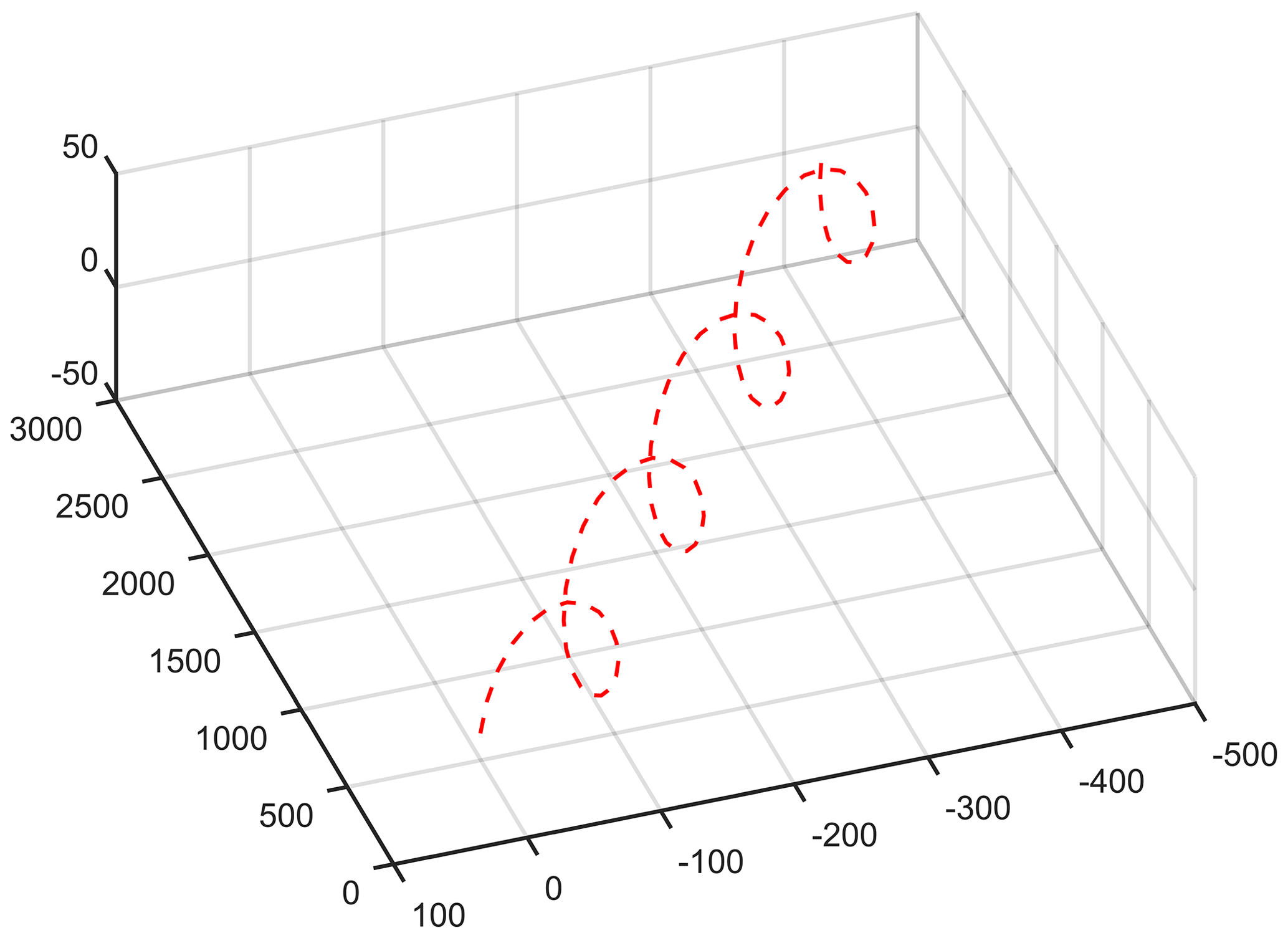
The trajectory of the spiral blades at is shown in Fig. 7.
4.2 Kinematic analysis of grain in spiral groove
The spiral blade of the screw transport drum and the inner shell form a closed space called the spiral groove. Between the spiral groove, grain particles do not interfere with each other. By simulating the motion of the grain particles under the action of spiral transport drum, the relationship between the axial velocity of grain particles and the motion parameters of spiral transport mechanism was deduced, as shown in Fig. 8.

In Fig. 8, vab is the chip removal velocity in the stationary coordinate system. vsl is the relative slip chip removal speed. vta is the linear speed of the screw transport mechanism at this point. vpe is the vertical velocity. η0 is the helix angle of the screw transport drum. αt is chip removal angle. The relation between the axial rising speed of the grain and other components is as follows (Hou et al., 2020):
Then, Eq. (10) can be expressed as follows:
vpe means that the higher the vertical velocity, the higher the transmission efficiency of the screw transport drum will be. The coefficient of the grain transport capacity can be expressed by the ratio ε of vertical velocity to the linear velocity of the screw transport mechanism at this point, and the expression is as follows:
It can also be expressed with the following formula:
where ω0 is the rotational speed of the screw transport drum, and R is the radius of the point of the screw transport drum.
4.3 Simulation of grain detector movement process based on DEM-MBD
Considering that it is difficult to observe the movement track of grain particles after the detector is immersed in the grain pile, it is even more difficult to observe the movement track of grain particles inside the detector. And the interaction between the grain particles and screw has a complex mechanical relationship. Therefore, DEM-MBD simulation is used in this section to verify the motion process of the detector and the motion status of particles inside it. In this experiment, EDEM, discrete element simulation software, and Adams multi-body dynamics simulation software were used for the coupling simulation. Due to the simulation of a granary environment producing a large number of particles, it will increase the number of calculations and the amount of simulation time. Compared with wheat and rice, soybeans with a larger single particle volume, larger gap ratio, and similar spherical shape were selected as the simulation particle material to reduce the number of calculations.
Compared with dense rock and concrete, the soybean stored in the granary is more dispersed, and the adhesion between grains is very small. Therefore, the Hertz–Mindlin bond model and linear spring model provided in EDEM are not applicable. As the detector moves through the grain pile, the interaction between the soybean particles is complex. However, tangential and normal forces can be described in a certain way. The Hertz–Mindlin model covers tangential and normal forces in the contact process (Owen and Cleary, 2009). It can explain the influence of elastic modulus and Poisson's ratio on contact force and is applicable to most materials with specific parameters. Therefore, the Hertz–Mindlin (no slip) model was used to solve the contact state between soybean particles and between detector and soybean.
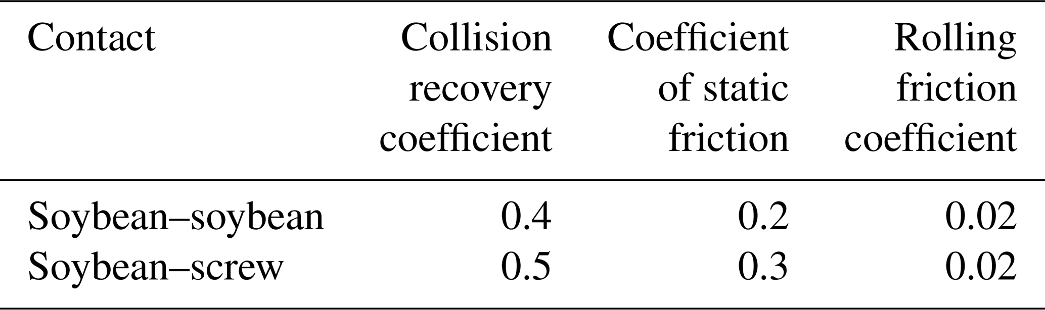
In EDEM, the particle model is modeled according to the actual size and shape of the soybeans, which results in a large increase in computation. In order to speed up the simulation, the soybean particle model was simplified to the equivalent sphere of 6 mm (Deshpande et al., 1993). The computer used for simulation was a professional workstation, and the processor was an Intel® Xeon® Gold 6154 CPU at 3.0 OG 2.99 GHz (two processors), the operating memory was 128 GB, and the maximum number of CPU cores was up to 72. It fully meets the operational requirements of EDEM. The rotational speed of the screw and the screw transport drum on the detector is controlled by Adams. The geometric parameters of the screw used in this simulation are shown in Table 1. The contact parameters are simplified and modified to facilitate the smooth progress of the simulation. Material parameters and simulation parameter settings are shown in Tables 2 and 3 (Ghodki et al., 2018; Yan et al., 2020).
In order to simulate the motion behavior of the detector when it is deep in the grain pile, the rotation speed of the screw and the screw transport drum should be set in Adams. In this simulation, the speed of the four screws was set at 300 rpm (revolutions per minute), and the speed of the screw transport drum was set at 420 rpm to ensure the transmission of grain. The gravity direction of the simulation environment is −y. The magnitude of the acceleration due to gravity is 9.8 m s−2. Through the interception of simulated images at different times, it can be clearly seen that the detector moves along the −Y direction under the action of the screw drive. At t=0.27 s, the particle is generated and stable after standing, the screw and the screw transport drum begin to rotate, and the detector starts to move. When t=3.27 s, the simulation is completed, and the whole device advances 95 mm along the −y direction. See Fig. 9 for more information.
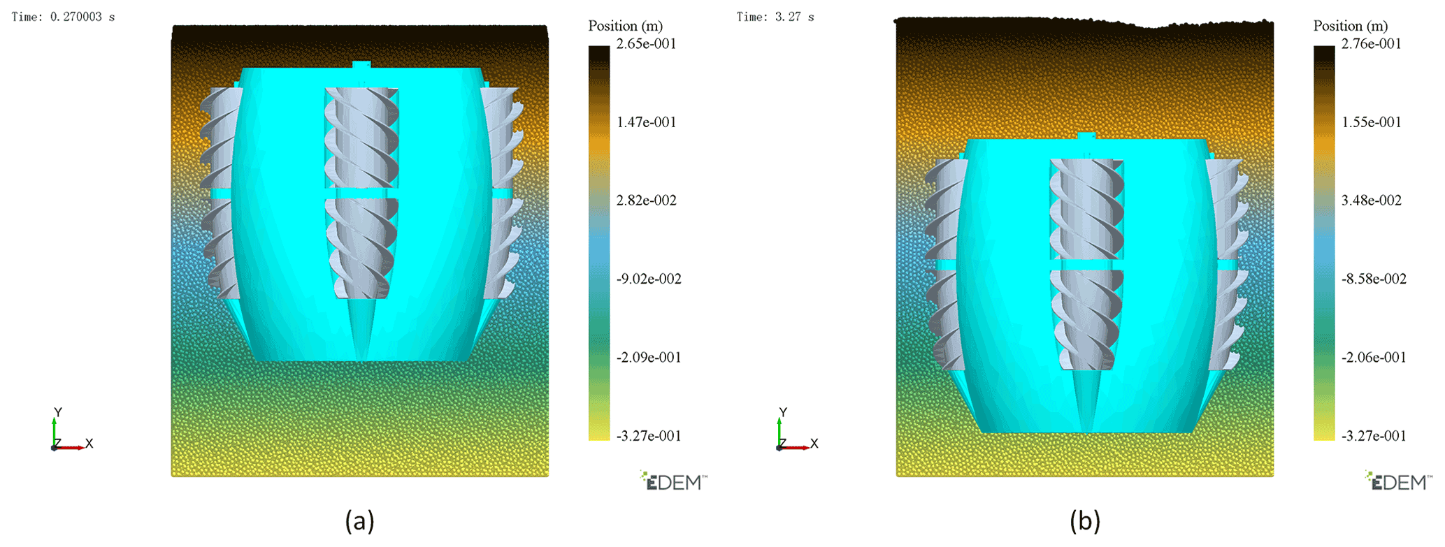
Figure 9Detector position changes. (a) Detector position at 0.27. (b) Position of detector at 3.27.
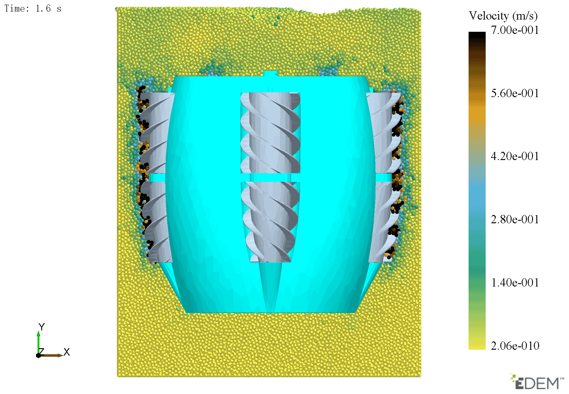
Figure 11 shows the velocity changes in particles around the screw transport drum and the direction of the velocity vector. It can be seen that particles move under the guidance of the spiral blade on the screw transport drum. The direction of the velocity vector is roughly consistent with the theoretical direction, and there is not too much disorder in the direction of the particle movement, but the particles are moving tangentially along the inner shell rather than efficiently along the drum. It shows that the setting speed of the spiral transport drum is greater than the required speed, which is not conducive to energy utilization. It generally achieves the goal of transporting grain particles from the front end of the detector to the back end. Since the simulation simulates the working condition after the detector is sunk into the grain pile, it needs to be stabilized after the particle generation, as shown in Fig. 10. Between t=0.27 s and t=0.65 s, the particles directly generated between the screw transport drum and the inner shell of the detector are discharged. At the later moments, the particles continuously enter the front end of the detector and are transmitted to the rear end of the detector through the screw transport drum. From t=1.6 s to t=3.27 s, the detector has already entered stable running. Since the screw speed on the detector rotates at a uniform speed, the particle velocity around the screw at the three moments does not change much, as shown in Fig. 11.
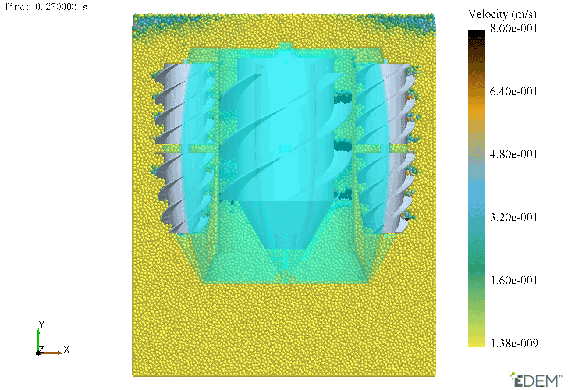
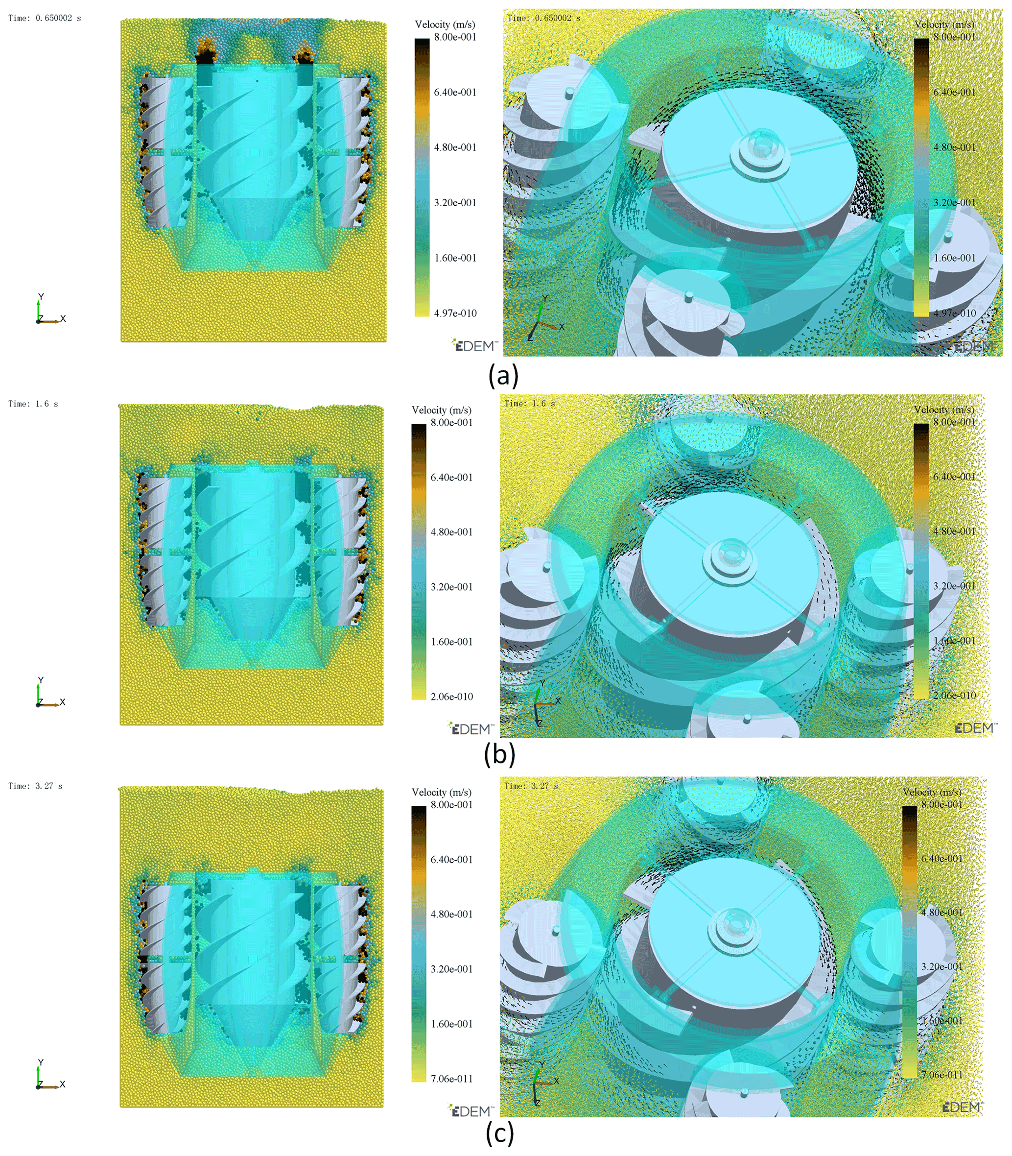
Figure 11Particle state and particle velocity vector transmitted by the screw transport drum at three moments.
The screw rotates to push the detector forward, and the spiral blades on the screw can divide the grain and exert force on the particles (see Fig. 12). The results show that the force distribution of particles near the screw is small and evenly distributed. The main force range is 0.12–0.18 N, and the maximum force range is 0.3–0.6 N. Particles around the periphery of the spiral blade will be subjected to a large force, and the distribution is relatively uniform. The force of particles between the spiral blades and close to the axis of the screw can be ignored. It shows that the force of the screw on grain layer is not only the normal stress exerted by screw but also the shear stress exerted by outer edge of the screw blade. The thrust generated by the screw is mainly generated by the shear stress. Combined with Fig. 13, it is found that the particle velocity between the spiral blades is the largest, which is close to the linear velocity of the screw drum. It shows that the grain layer between the spiral blades and the screw can be regarded as one.

Figure 12t=1.6 s force on particles around the screw. The maximum value of the legend in panel (a) is 0.3 N, the maximum value of legend in panel (b) is 0.6 N, and the minimum values of the two are the same.
4.4 The influence of key factors on maneuverability of detector
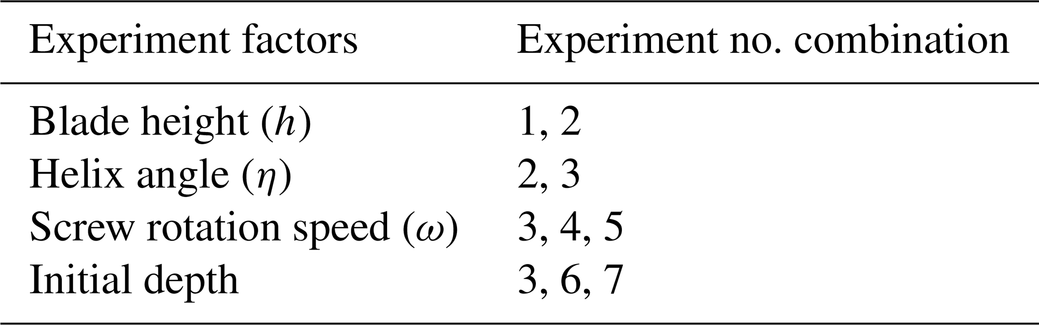
Through a single factor experiment. The effects of the screw angle, blade height and screw speed on detector's motion performance were studied. The influence of different depth operations in the grain pile on detector velocity is also studied. By coupling EDEM software with Adams multi-body dynamics software, the simulation results under different levels of the same factor are obtained and analyzed. The aim is to find the key parameters which have a great influence on the performance of the detector. The experimental arrangement is shown in Table 4, and different combinations of experiment numbers correspond to different experimental purposes. The purpose of the experiment is to find out the factors that have significant influence on the motion performance of the detector. The combination of experimental numbers and their experimental purposes are shown in Table 5.
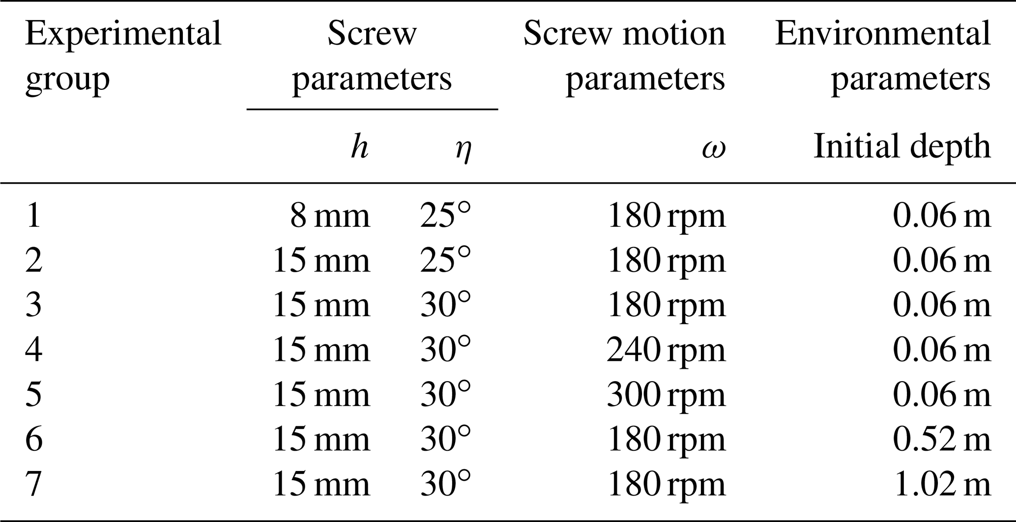
The experimental results are derived by simulation. Figure 14 shows the velocity change curves at different times in Experiment 1. Experimental errors lead to useless peaks in experimental data, which is not convenient for analyzing the experimental data and reading the graph. The experimental data need to be filtered. Then, the experimental results of different experimental purposes will be calculated and analyzed, and the influence degree of four different factors in Table 5 on the motion performance of the detector will be obtained.
Table 4Simulation experiment arrangement of single factor change.
Experimental data of different spiral blade heights were obtained according to simulation experiments, as shown in Figs. 15 and 16.
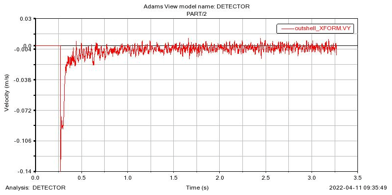
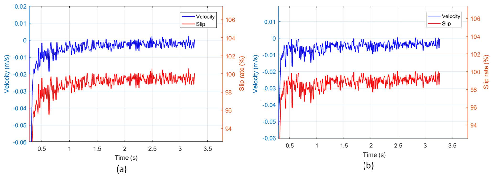
Figure 15Velocity and slip rate corresponding to different helical blade heights. (a) h=8 mm. (b) h=15 mm.
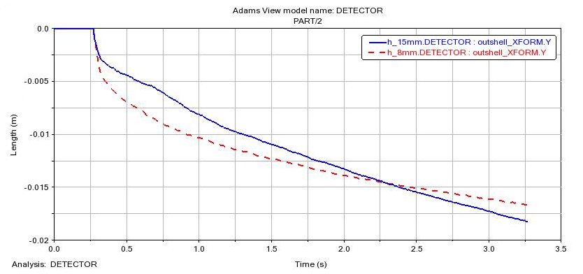
Because the detector moves in the negative direction of y axis, the velocity direction obtained by simulation is mostly negative. According to Fig. 15, the speed corresponding to h=8 mm is slightly lower than that corresponding to h=15 mm. The slip rate curve calculated by h=8 mm is slightly higher than that calculated by h=15 mm. The average speed and slip rate corresponding to h=8 mm are 0.0051 m s−1 and 98.77 %, respectively. The average speed and slip rate corresponding to h=15 mm are 0.0055 m s−1 and 98.60 %, respectively. It can be seen that the screw slip rate is high due to the large resistance. However, the increase in blade height also brings a positive effect to the increase in speed, and the slip rate decreases slightly. The comprehensive detail in Fig. 16 shows that the speed corresponding to h=8 mm before 0.5 s is greater than that corresponding to h=15 mm. The resistance increases with the increase in driving depth. The smaller spiral blades could not effectively separate grain layers, leading to a gradual increase in the slip rate and a gradual decline in velocity. In contrast, the displacement curve corresponding to h=15 mm shows that the attenuation of velocity decreases significantly.
The helix angle is also an important factor affecting the detector's walking performance. It can be seen by comparing Figs. 17 and 18.
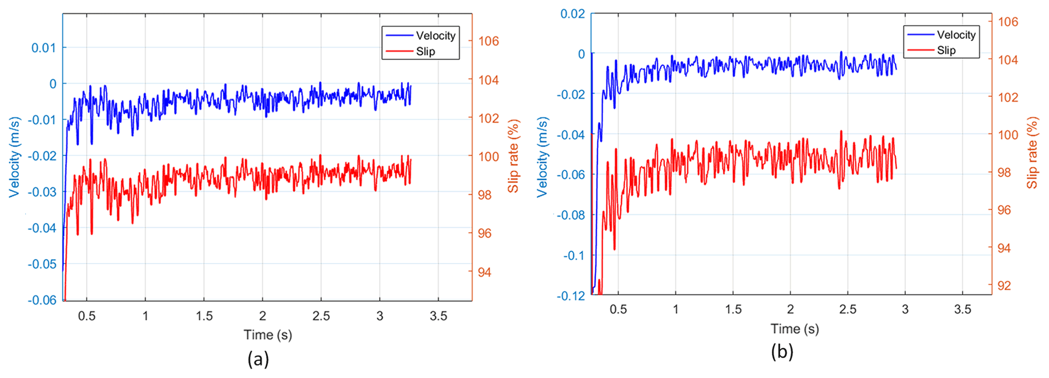
Figure 17Velocity and slip rate corresponding to different spiral lift angles. (a) η=25∘. (b) η=30∘.
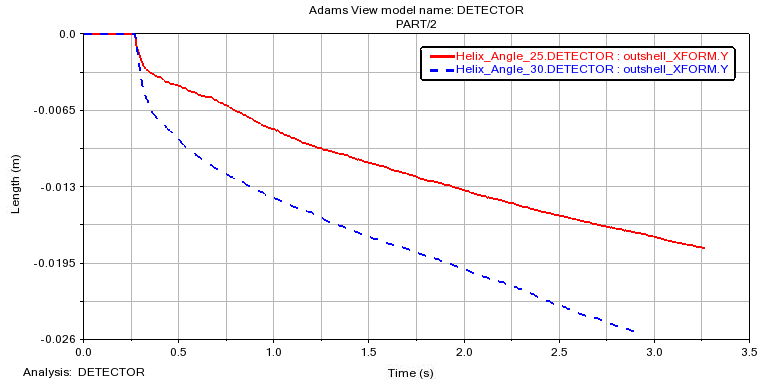
Figure 17 shows that the maximum speed of the detector with η of 25∘ is no more than 0.02 m s−1 after it is stationary in motion, which is obviously smaller than that of the detector with η of 30∘, and the slip rate is on the contrary. The reason for the above results is that the increase in spiral angle will increase the pitch. The increase in the pitch will naturally increase the efficiency of the screw cutting the grain layer. Eventually, the screw speed is increased, and the slip rate is reduced under the condition of constant rotation speed. The average speed and slip rates of η=25∘ are 0.0055 m s−1 and 98.60 %, respectively. η=30∘ corresponds to average speed and slip rates of 0.0086 m s−1 and 98 %. In Fig. 18, the displacement of η=25∘ is significantly smaller than that of η=30∘, and the velocity is always smaller than that of η=30∘. It indicates that the increase in helix angle from 25 to 30∘ is beneficial to the motion of detector, which confirms the theory of Cole (1961).
The increase in the screw rotation speed will lead to the increase in detector motion speed, but the change in speed and slip rate in the environment inside the grain pile needs further verification, as shown in Figs. 19 and 20.
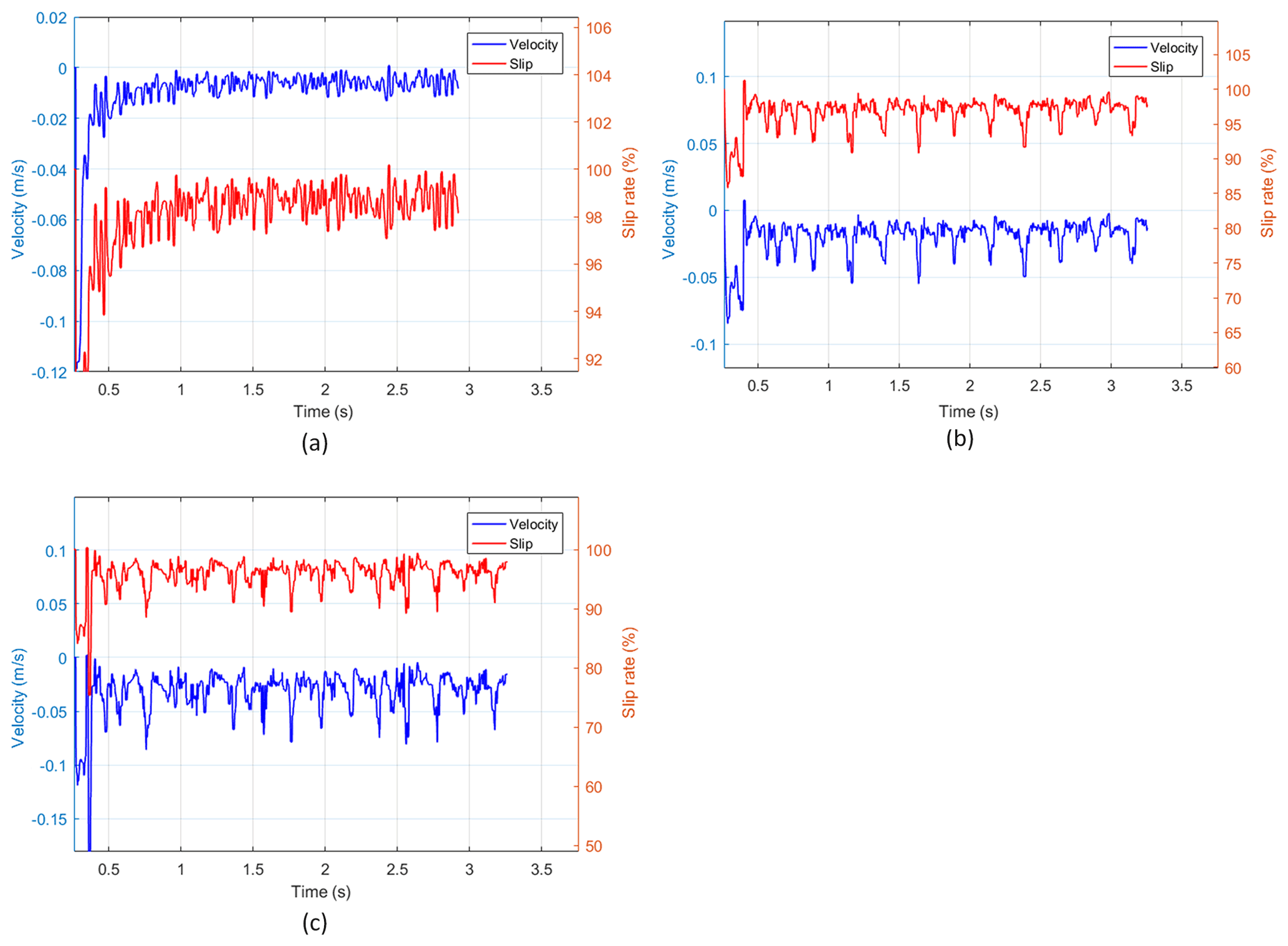
Figure 19Speed and slip rate corresponding to different screw speeds. (a) ω=180 rpm. (b) ω=240 rpm. (c) ω=300 rpm.
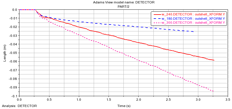
Combined with Figs. 19 and 20, it is shown that, with the increase in the screw rotation speed, the motion speed of the detector increases significantly. The slip rate also decreases with the increase in rotational speed. The screw rotation speeds of 180, 240, and 300 rpm are 0.0086, 0.0182, and 0.03 m s−1, respectively, and the corresponding slip rates are 98 %, 96.94 %, and 95.9 %. The screw rotation speed increases at a speed of 60 rpm. Combined with the image, it can be seen that the relationship between the three speed gradients and the corresponding speed is close to a linear increase. The magnitude of displacement is also close to a linear increase. The magnitude of the slip rate is also close to a linear decrease. It shows that the increase in the screw rotation speed within a certain range is beneficial for reducing the slip rate and improving the motion speed of the detector.
As the detector needs to go deep into the interior of the granary, it is necessary to study the kinematic rules at different depths. Figures 21 and 22 show the kinematic images at three depths.
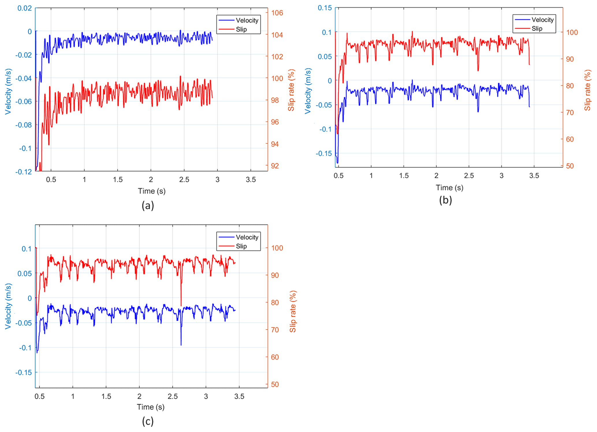
Figure 21Velocity and slip rate at different initial depths. (a) Initial depth is 0.06 m. (b) Initial depth is 0.52 m. (c) Initial depth is 1.02 m.
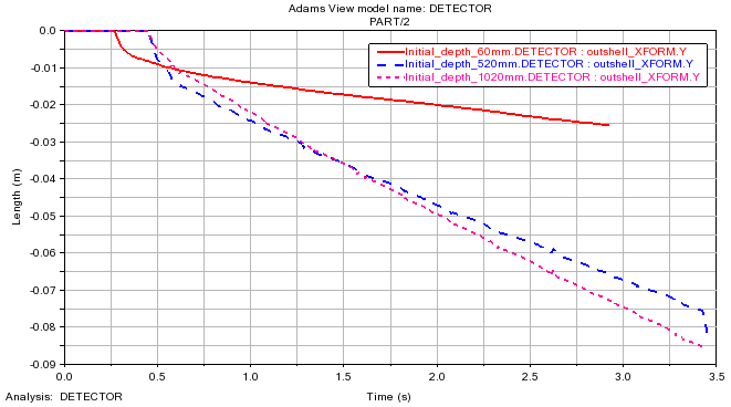
As the initial depth increases, as shown in Fig. 21, the velocity corresponding to different depths also increases, and the slip rate decreases. The average speed corresponding to the three initial depths of 0.06, 0.52, and 1.02 m is 0.0086, 0.0218, and 0.026 m s−1, respectively, and the average slip rate corresponding to them is 98 %, 95.11 %, and 94.18 %, respectively. Combined with Fig. 22, it can be shown that, compared with the change in speed and slip rate at the initial depth of 0.06 to 0.52 m, the change in speed and slip rate corresponding to the initial depth of 0.06 to 1.02 m is greatly reduced. It indicates that the motion speed of the detector is positively correlated with the depth under the condition of a constant screw speed. The possible reason for this phenomenon is that, with the increase in the depth of the granary, the pressure in the granary increases, and the porosity between grains decreases, which leads to the enhancement of the force between the screw and grains and thus reduces the slip rate. When the detector reaches a certain depth, the slip rate decreases and the speed increases slowly. The reason may be related to the mechanical properties inside the grain pile.
4.5 Simulation and analysis of detector steering motion
After the verification in Sect. 4.4, it is found that the relationship between the screw speed and movement speed is linear. It is assumed that the differential steering of the detector can be realized through the speed difference between the screws. However, the interaction between the screw and grain layer is very complex. Its kinematic and mechanical behavior remains to be clarified if the screw is turned in the internal environment of a grain pile. Therefore, on the basis of simulation verification and simulation, the results are analyzed. The geometric parameters of the simulated screw are the same as those in Table 1. The contact parameters and contact parameters between the detector and granular materials are shown in Tables 2 and 3. The simulation start is shown in Fig. 23.

In Fig. 23, when t=0.55 s, the detector is at rest at the initial position. The gravity direction is −Y, and the detector is moving in the −Y direction and turning around the X axis toward the Z axis. Figure 5 shows the relationship between the screw speed and the overall movement direction of the mechanism, which will not be described too much here. Only the rotation speed of the screw is taken as the influencing factor in the experiment. Two groups of experiments were set as the control, and the rotational speed ratio between the two groups of the screw was 4 : 1 and 2 : 1, respectively. The screw rotation ratio and speed in the two groups of experiments are shown in Table 6.
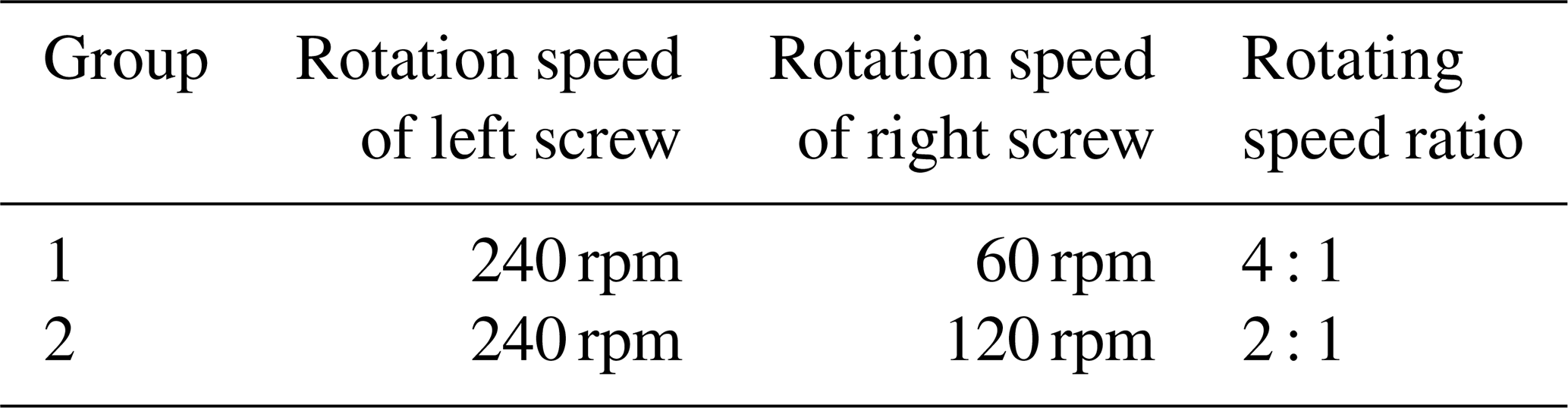

Figure 24Simulation of the screw speed ratio of 4 : 1 (a) and screw speed ratio of 2 : 1 (b), when t=2.16 s, t=4.32 s, and t=6.5 s.
The simulation results of Experiment 1 and Experiment 2 are shown in Fig. 24.
At the beginning of t=2.16 s, the speed of the detector with a rotational ratio of 2 : 1 in the Y direction is greater than that of the detector with a rotational ratio of 4 : 1 in the Y direction. The former has a greater effect on particles. From t=4.32 s and T=6.5 s, respectively, the effect of the detector with screw rotation ratio of 4 : 1 on particles is greater than that of the detector with screw rotation ratio of 2 : 1. It indicates that, after entering the steering process for a period of time, the increase in the speed difference increases the torque of the detector. In general, the displacement of the detector in Experiment 2 in the −Y direction is greater than that in Experiment 1.
The steering angle of the detector is also an important experimental result, which is the key to evaluating the steering ability of the detector.
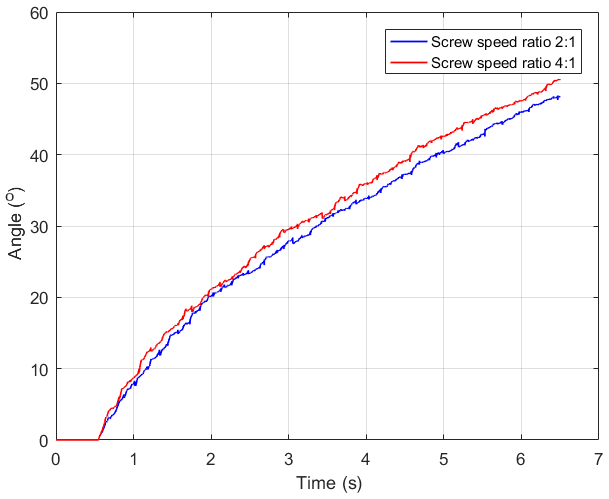
In Fig. 25, the steering angle of the detector in Experiment 1 is always larger than that in Experiment 2. The difference between the two has grown over time. Combined with the displacement of the detector in the −Y direction in Experiments 1 and 2, it can be shown that the steering radius of the detector in Experiment 1 is smaller. When the detector is steering, the steering radius is reduced by increasing the speed difference between the two groups of the screws, and the turning is finally completed.
This paper presents a drill-in granary grain condition detector. The scheme design of the drill-in granary grain condition detector and its walking process in grain pile are established. The kinematic model of a single screw was established, and the kinematic diagram was obtained by calculation and simulation, based on DEM-MBD. It was found that grain particles near the screw drum could be regarded as one with the screw. The kinematic model of the grain particles in the screw transport mechanism was established, and the motion state of grain particles in spiral groove was observed through simulation images. It is concluded that grain particles move under the guidance of spiral blades on screw transport drum. The idea that the particle velocity vector direction is consistent with the theoretical direction is confirmed. It can transport grain from the front end of the detector to the back end. Through experimental analysis, the increase in the screw blade height reduces the slip rate and effectively reduces the velocity attenuation caused by the working depth. The helix angle on the screw changes from 25 to 30∘, so that the speed of the detector increases and the slip rate decreases. The moving speed of the detector increases significantly as the screw rotation speed increases. The incremental relationship between the two is close to linear. Increasing the depth of the detector will increase the speed of the detector and reduce the slip rate. However, when the depth reaches 1.02 m, the range of variation decreases greatly. In the detector steering experiment, it is found that the larger the rotational speed ratio of two pairs of the screws, the smaller the steering radius will be. At present, only the kinematics of the model is studied. The mechanical properties between the detector and grain are the focus of the next step, and the corresponding theory has been used as support. In terms of kinematics, the future plan is to do an experimental verification on a prototype and design a reasonable orthogonal experiment to find out the optimal parameter setting for the future optimization design.
Code and data can be made available upon request to the corresponding author.
JY, QY, and YZ contributed ideas. JY wrote the first draft of the paper. JY and AH completed the review and editing of the paper. JY performed the kinematic analysis of the mechanism. JY and SS provided software technical support. JY conducted the simulation experiments. JY and QY completed the experimental analysis. GZ and ZH sourced the funding.
The contact author has declared that none of the authors has any competing interests.
Publisher's note: Copernicus Publications remains neutral with regard to jurisdictional claims in published maps and institutional affiliations.
The authors are grateful for the support received from various third parties (see the financial support section) that made this work possible.
The project has been supported by the Open Fund of the Hubei Key Laboratory of Mechanical Transmission and Manufacturing Engineering at the Wuhan University of Science and Technology (grant no. MTMEOF2021B01). This research has also been supported by the Hubei Province Unveiling Food Science And Technology Project (grant no. 2021kjcx-01) and Wuhan Polytechnic University Research Grant (grant no. 2021Y23).
This paper was edited by Daniel Condurache and reviewed by two anonymous referees.
Abramson, D., Hulasare, R., York, R. K., White, N. D. G., and Jayas, D. S.: Mycotoxins, ergosterol, and odor volatiles in durum wheat during granary storage at 16 % and 20 % moisture content, J. Stored Prod. Res., 41, 67–76, https://doi.org/10.1016/j.jspr.2003.11.002, 2005.
Banga, K. S., Kotwaliwale, N., Mohapatra, D., and Giri, S. K.: Techniques for insect detection in stored food grains: An overview, Food Control, 94, 167–176, https://doi.org/10.1016/j.foodcont.2018.07.008, 2018.
Brown, P. R., McWilliam, A., and Khamphoukeo, K.: Post-harvest damage to stored grain by rodents in village environments in Laos, Int. Biodeter. Biodegr., 82, 104–109, https://doi.org/10.1016/j.ibiod.2012.12.018, 2013.
Cole, B.: Inquiry into amphibious screw traction, Proceedings of the Institution of Mechanical Engineers, 175, 919–940, https://doi.org/10.1243/PIME_PROC_1961_175_060_02, 1961.
Darbois Texier, B., Ibarra, A., and Melo, F.: Helical Locomotion in a Granular Medium, Phys. Rev. Lett., 119, 068003, https://doi.org/10.1103/PhysRevLett.119.068003, 2017.
Deichmann, U., Goyal, A., and Mishra, D.: Will digital technologies transform agriculture in developing countries?, Agr. Econ., 47, 21–33, https://doi.org/10.1111/agec.12300, 2016.
Deshpande, S., Bal, S., and Ojha, T.: Physical properties of soybean, J. Agr. Eng. Res., 56, 89–98, https://doi.org/10.1006/jaer.1993.1063, 1993.
Duan, S., Yang, W., Wang, X., Mao, S., and Zhang, Y.: Forecasting of Grain Pile Temperature From Meteorological Factors Using Machine Learning, IEEE Access, 7, 130721–130733, https://doi.org/10.1109/access.2019.2940266, 2019.
Dugoff, H. and Ehlich, I. R.: Model tests of bouyant screw rotor configurations, J. Terramechanics, 4, 9–22, https://doi.org/10.1016/0022-4898(67)90123-1, 1967.
Eimanis, M. and Auzins, J.: Research of dynamics of double helicoidal vehicle in granular media, Eng. Rur. Develop., Jelgava, 1205–1209, https://doi.org/10.22616/ERDev2019.18.N358, 2019.
Feinstein, L.: Grain Storage–the Role of Fungi in Quality Loss, Bulletin of the Entomological Society of America, 15, 259, https://doi.org/10.1093/besa/15.3.259, 1969.
Ghodki, B. M., Patel, M., Namdeo, R., and Carpenter, G.: Calibration of discrete element model parameters: soybeans, Computational Particle Mechanics, 6, 3–10, https://doi.org/10.1007/s40571-018-0194-7, 2018.
Gitonga, Z. M., De Groote, H., Kassie, M., and Tefera, T.: Impact of metal silos on households' maize storage, storage losses and food security: An application of a propensity score matching, Food Policy, 43, 44–55, https://doi.org/10.1016/j.foodpol.2013.08.005, 2013.
Gonzales, H. B., Armstrong, P. R., and Maghirang, R. G.: Simultaneous monitoring of stored grain with relative humidity, temperature, and carbon dioxide sensors, American Society of Agricultural and Biological Engineers, 25, 595–604, https://doi.org/10.13031/2013.27466, 2009.
Green, M., McBryan, T., Mick, D., Nelson, D., and Marvi, H.: Regolith Excavation Performance of a Screw-Propelled Vehicle, Advanced Intelligent Systems, https://doi.org/10.1002/aisy.202100125, online first, 2021.
Henny, G. E. J. and Stamm, P. H. H.: 27. The construction and operation of grain silos in developing countries, in: APPROPRIATE TECHNOLOGY IN CIVIL ENGINEERING, Thomas Telford Publishing, 107–109, 1981.
Hou, X., Guo, H., Cao, P., Xue, P., Tang, T., and Deng, Z.: Research on a lunar mobile spiral surface-soil sampler, Adv. Mech. Eng., 12, 1687814018817114, https://doi.org/10.1177/1687814018817114, 2020.
Knight, S. J., Rush, E. S., and Stinson, B. G.: Trafficability tests with the marsh screw amphibian, J. Terramechanics, 2, 31–50, https://doi.org/10.1016/0022-4898(65)90130-8, 1965.
Kumar, D. and Kalita, P.: Reducing Postharvest Losses during Storage of Grain Crops to Strengthen Food Security in Developing Countries, Foods, 6, 8, https://doi.org/10.3390/foods6010008, 2017.
Li, D., Huang, S., Tang, Y., Marvi, H., Tao, J., and Aukes, D. M.: Compliant Fins for Locomotion in Granular Media, IEEE Robotics and Automation Letters, 6, 5984–5991, https://doi.org/10.1109/lra.2021.3084877, 2021.
Liu, X., Li, B., Shen, D., Cao, J., and Mao, B.: Analysis of grain storage loss based on decision tree algorithm, Procedia Comput. Sci., 122, 130–137, https://doi.org/10.1016/j.procs.2017.11.351, 2017.
Lu, C.: Wireless Granary Temperature and Humidity Monitoring System, Adv. Mat. Res., 217–218, 1536–1540, https://doi.org/10.4028/www.scientific.net/AMR.217-218.1536, 2011.
Lutful, K., Alagan, A., Nidal, N., and Almhana, J.: Sensor-based M2M Agriculture Monitoring Systems for Developing Countries: State and Challenges, Netw. Protoc. Algorithms, 5, 68–86, https://doi.org/10.5296/npa.v5i3.3787, 2013.
Magan, N. and Aldred, D.: Post-harvest control strategies: Minimizing mycotoxins in the food chain, Int. J. Food Microbiol., 119, 131–139, https://doi.org/10.1016/j.ijfoodmicro.2007.07.034, 2007.
Maier, D. E., Channaiah, L., Martinez-Kawas, A., Lawrence, J., Chaves, E., Coradi, P., and Fromme, G.: Monitoring carbon dioxide concentration for early detection of spoilage in stored grain, Julius-Kühn-Archiv, 505, https://doi.org/10.5073/jka.2010.425.332, 2010.
Manandhar, A., Milindi, P., and Shah, A.: An Overview of the Post-Harvest Grain Storage Practices of Smallholder Farmers in Developing Countries, Agriculture, 8, 57, https://doi.org/10.3390/agriculture8040057, 2018.
Mannaa, M. and Kim, K. D.: Influence of Temperature and Water Activity on Deleterious Fungi and Mycotoxin Production during Grain Storage, Mycobiology, 45, 240–254, https://doi.org/10.5941/myco.2017.45.4.240, 2018.
Nagaoka, K., Kubota, T., and Tanaka, S.: Maneuverability Analysis of Screw Drive Rover on Soft Terrain, 9th Asia-Pacific ISTVS Conference, and Annual Meeting of Japanese Society for Terramechanics, 18–20 October 2010, 2010a.
Nagaoka, K., Otsuki, M., Kubota, T., and Tanaka, S.: Terramechanics-based propulsive characteristics of mobile robot driven by Archimedean screw mechanism on soft soil, 2010 IEEE/RSJ International Conference on Intelligent Robots and Systems, Taipei, Taiwan, https://doi.org/10.1109/IROS.2010.5651010, 2010b.
Neethirajan, S., Jayas, D. S., and Sadistap, S.: Carbon Dioxide (CO2) Sensors for the Agri-food Industry – A Review, Food Bioprocess Tech., 2, 115–121, https://doi.org/10.1007/s11947-008-0154-y, 2008.
Neethirajan, S., Freund, M. S., Jayas, D. S., Shafai, C., Thomson, D. J., and White, N. D. G.: Development of carbon dioxide (CO2) sensor for grain quality monitoring, Biosyst. Eng., 106, 395–404, https://doi.org/10.1016/j.biosystemseng.2010.05.002, 2010.
Neumeyer, M. and Jones, B.: The marsh screw amphibian, J. Terramechanics, 2, 83–88, https://doi.org/10.1016/0022-4898(65)90133-3, 1965.
Newman, C.: Storage and ancillary equipment for bulk handling of grain, International Workshop on Bulk Handling and Storage of Grain in Humid Tropic, 6–9 October 1987, Kuala Lumpur, Malaysia, https://ageconsearch.umn.edu/record/134377 (last access: 15 November 2022), 1987.
Olorunfemi, B. J. and Kayode, S. E.: Post-Harvest Loss and Grain Storage Technology – A Review, Turk. J. Agric. – Food Science and Technology, 9, 75–83, https://doi.org/10.24925/turjaf.v9i1.75-83.3714, 2021.
Onibonoje, M. O., Nwulu, N. I., and Bokoro, P. N.: A wireless sensor network system for monitoring environmental factors affecting bulk grains storability, J. Food Process Eng., 42, e13256, https://doi.org/10.1111/jfpe.13256, 2019.
Owen, P. and Cleary, P.: Prediction of screw conveyor performance using the Discrete Element Method (DEM), Powder Technol., 193, 274–288, https://doi.org/10.1016/j.powtec.2009.03.012, 2009.
Pan, J., Chen, J., and Li, J.: Dynamical behaviors of self-propulsion intruder buried in granular materials, Soft Matter, 17, 9997–10004, https://doi.org/10.1039/d1sm00934f, 2021.
Qi, S. and Li, Y.: The Design of Grain Temperature-Moisture Monitoring System Based on Wireless Sensor Network, in: Communications and Information Processing, edited by: Zhao, M. and Sha, J., Communications in Computer and Information Science, Vol. 289, Springer, Berlin, Heidelberg, https://doi.org/10.1007/978-3-642-31968-6_53, 2012.
Ramachandran, R. P.: Integrated approach on stored grain quality management with CO2 monitoring-A review, J. Stored Prod. Res., 96, 101950, https://doi.org/10.1016/j.jspr.2022.101950, 2022.
Safar, M. J. A., Samsol, M. H., Ismail, A. H., Basah, S. N., Basaruddin, K. S., and Salleh, A. F.: Design and Development of a Reconfigurable Screw-wheeled Omnidirectional Mobile Robot, IOP Conf. Ser.-Mat. Sci., 705, 012041, https://doi.org/10.1088/1757-899x/705/1/012041, 2019.
Schmidt, M., Horstmann, S., De Colli, L., Danaher, M., Speer, K., Zannini, E., and Arendt, E. K.: Impact of fungal contamination of wheat on grain quality criteria, J. Cereal Sci., 69, 95–103, https://doi.org/10.1016/j.jcs.2016.02.010, 2016.
Singh, C. B. and Fielke, J. M.: Recent developments in stored grain sensors, monitoring and management technology, IEEE Instrumentation and Measurement Magazine, 20, 32–55, https://doi.org/10.1109/MIM.2017.7951690, 2017.
Thoesen, A., Ramirez, S., and Marvi, H.: Screw-powered propulsion in granular media: An experimental and computational study, 2018 IEEE International Conference on Robotics and Automation (ICRA), 21–25 May 2018, Brisbane, Australia, https://doi.org/10.1109/ICRA.2018.8460916, 2018.
Thoesen, A., McBryan, T., Mick, D., Green, M., Martia, J., and Marvi, H.: Granular scaling laws for helically driven dynamics, Phys. Rev. E, 102, 032902, https://doi.org/10.1103/PhysRevE.102.032902, 2020.
Wang, T., Zhao, D., Zhang, X., Wang, L., and Ding, L.: Design of Granary Temperature and Humidity Monitoring System Based on STM32 and Multi-Sensor Data Fusion, in: Proceedings of the 2nd International Conference on Green Communications and Networks 2012 (GCN 2012): Volume 4, Lecture Notes in Electrical Engineering, 115–121, https://doi.org/10.1007/978-3-642-35440-3_16, 2013.
Wu, W., Cui, H., Han, F., Liu, Z., Wu, X., Wu, Z., and Zhang, Q.: Digital monitoring of grain conditions in large-scale bulk storage facilities based on spatiotemporal distributions of grain temperature, Biosyst. Eng., 210, 247–260, https://doi.org/10.1016/j.biosystemseng.2021.08.028, 2021.
Yan, D., Yu, J., Wang, Y., Zhou, L., and Yu, Y.: A general modelling method for soybean seeds based on the discrete element method, Powder Technol., 372, 212–226, https://doi.org/10.1016/j.powtec.2020.05.054, 2020.
Yu, L., Zhang, Q., Meng, X., and Yan, Z.: Design of the granary temperature and humidity measure and control systembased on Zigbee wireless sensor network, 2011 International Conference on Electrical and Control Engineering, 16–18 September 2011, Yichang, China, https://doi.org/10.1109/ICECENG.2011.6057835, 2011.
Ziegler, V., Paraginski, R. T., and Ferreira, C. D.: Grain storage systems and effects of moisture, temperature and time on grain quality – A review, J. Stored Prod. Res., 91, 101770, https://doi.org/10.1016/j.jspr.2021.101770, 2021.