the Creative Commons Attribution 4.0 License.
the Creative Commons Attribution 4.0 License.
 | 08 Nov 2022
The evolution and restoration of European vertically arranged mechanical turret clocks before the 17th century
Tsung-Yi Lin
Wen-Feng Lin
From the 14th to 17th century in Europe, a variety of types of mechanical turret clocks were manufactured, many of which have been replaced or abandoned. At present, vertically arranged mechanical turret clocks can be rarely found. This study mainly analyzed the mechanism and technology of nine existing vertically arranged mechanical turret clocks manufactured in Europe from the 15th to the 17th century, in order to determine the design rules based on mechanical evolution and variation. The systematical restoration of vertically arranged mechanical turret clocks in history has resulted in 16 representative mechanism configurations of movements of mechanical turret clocks. The content and results of this study can provide its readers a clearer understanding about the mechanism design and technology of the vertically arranged mechanical turret clocks of each period throughout history in order to establish a comprehensive knowledge system. Furthermore, understanding the design concept of the vertically arranged mechanical turret clock contributes to the establishment of every possible restoration design construction throughout history. These innovative results not only provide new historical materials that could be applied in the research of science and technology history, but also contribute to the development of creativity and science education teaching materials.
- Article
(9208 KB) - Full-text XML
- BibTeX
- EndNote


European mechanical clocks designed and manufactured from the 14th to the 18th century are a combination of technology and culture and have played an important role in the development of modern mechanical science and technology. The restoration and translation of mechanical clocks constitute a type of multi-disciplinary research involving science, technology, craft, history, culture, and life. Thus, this study contributes to the promotion of science and history for young people.
Table 1Basic information of the existing representative vertically arranged mechanical turret clocks.
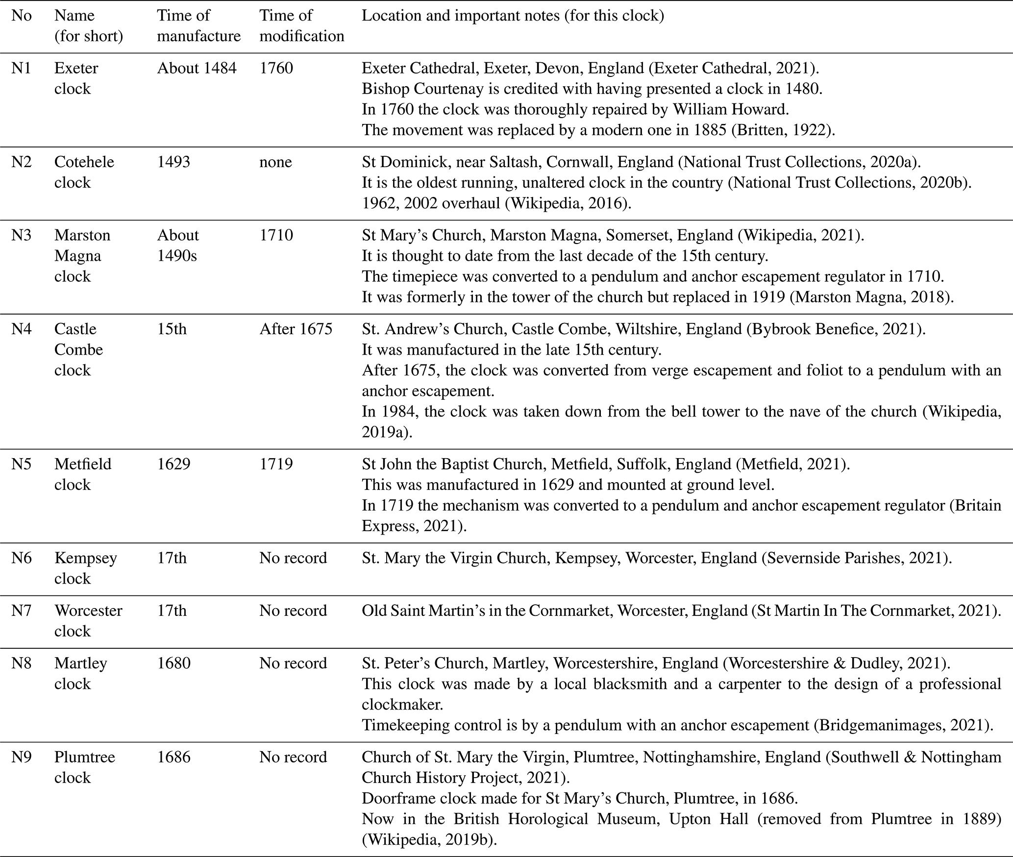
Currently, only a few of the studies in literature related to mechanical turret clocks have systematic professional knowledge and technical content; most of them are introductory, and the content mainly focuses on the repair, maintenance, and introduction of the historical culture of a specific mechanical turret clock. The reference literature has been organized in the form of Table 1. Hence, this study will not further discuss the content of the reference literature.
The two main key points of this study are as follows: (1) the mechanism and motion analysis of history's most representative vertically arranged mechanical turret clocks, focusing on their mechanism design evolution and variation, through which the technical context and innovative design thinking in the development of the vertically arranged mechanical turret clock was comprehended, systematically constructing a technical and knowledge system for the vertically arranged mechanical turret clock, which will serve as teaching material for the further development of creativity and science education in technology literacy education, and (2) the mechanism configuration synthesis of the vertically arranged mechanical turret clocks based on our restoration results and their technical context, using the mechanism configuration synthesis results and the mechanism analysis results of these representative vertically arranged mechanical turret clocks to further restore all feasible designs of the vertically arranged mechanical turret clocks in history, which provides new historical materials that could be applied in the research of science and technology history.
The method of mechanical evolution and variation applied in this study refers to the means to explore the evolvement of technology and design in a certain mechanical system, with focuses on the creation and accumulation of technology, improvement in materials, processing technology, and the promotion of social needs (Liang and Liang, 2000; Lin, 2020; Yan, 2009).
Since the 13th century, mechanical turret clocks have been used to tell the time in churches. From the 14th to the 17th century, various structures were developed and widely used across Europe. Due to the geographical factors and the COVID-19 pandemic, this study was unable to obtain original materials on the clock structures but collected abundant existing literature for analysis.
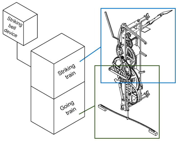
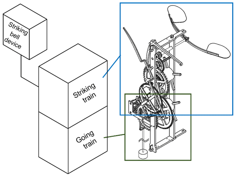
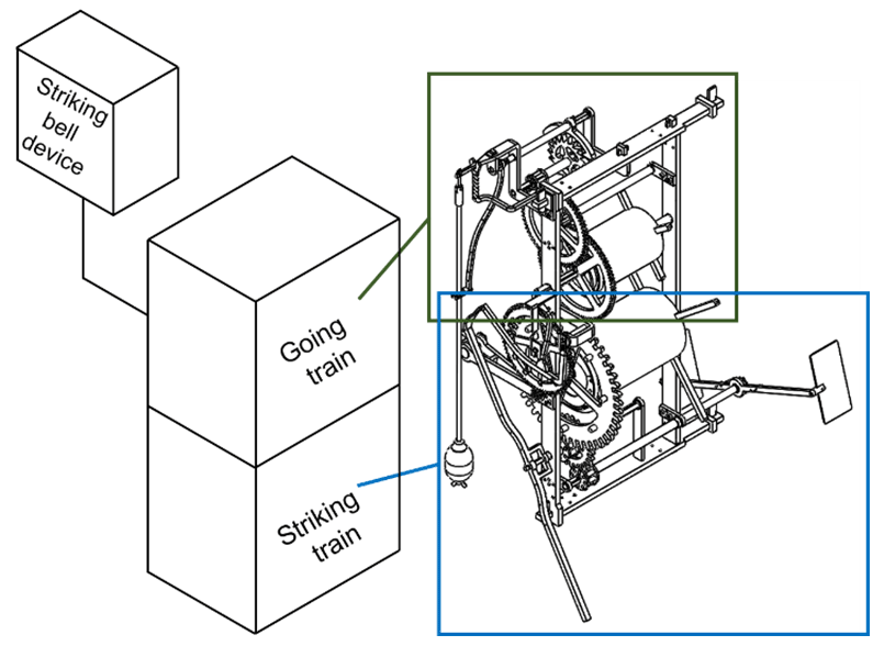
According to the literature on existing clocks, this study analyzed and compared the mechanisms of nine existing representative vertically arranged mechanical turret clocks (listed in Table 1) to explore their technology, restore the structures, and replicate the clock movements that have been modified or destroyed from the 14th to the 17th century. The vertically arranged mechanical turret clock generally refers to clocks in which the going train and striking train of the movement, particularly the power shafts, are installed vertically in a frame. Figure 1 shows the Cotehele clock (Frank, 2013; McKay, 1998), which has one of the earliest movement structures of mechanical turret clocks. Another common movement structure of mechanical turret clocks before the 17th century was the end-to-end structure of the Salisbury clock.
Table 1 presents a list of clocks organized by the manufacturing time. The Exeter clock, Marston Magna clock, Castle Combe clock, and Cotehele clock were manufactured in the 15th century, according to research. However, only the movement of the Cotehele clock has not been modified, while all others have been modified since 1675. Therefore, this study took the Cotehele clock of 1493 as the original structure of the vertically arranged mechanical turret clock to analyze the mechanism for the discussion of the evolution of the technology.
Current historical information has not confirmed whether the Cotehele clock is the earliest vertically arranged mechanical turret clock, but it is the earliest vertically arranged mechanical turret clock in existence (National Trust Collections, 2020b). Therefore, this study first performed a mechanism analysis of the Cotehele clock to know the original structure of vertically arranged mechanical turret clocks. As shown in Fig. 1, the movement of the Cotehele clock includes a going train and a striking train, which are installed in a vertical fashion. The iron frame of the movement is rectangular and fixed onto a wooden frame.

3.1 Mechanism analysis of the going train
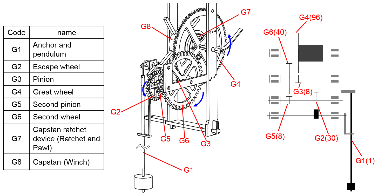
As shown in Fig. 2, the going train includes a power device, a going gear train, and an escapement regulator. The striking trigger lever (L1) outputs a signal to the striking train to begin moving.
-
The power device includes a capstan (the power rope wheel, the rope, and the weight) and a capstan ratchet device, which provides power for the going train through the torsion generated by the weight acting on the power rope wheel.
-
The going train only has one gear train. The great wheel (the minute wheel) is fixed to the great wheel shaft and co-axial with the power rope wheel, while the pinion is co-axial with the crown wheel. The speed ratio is designed to make the great wheel finish one complete revolution every hour ( rpm).
-
The escapement regulator is composed of a foliot and a verge escapement (the verge and the crown wheel). The swinging period of the foliot is one timing unit (12 s).
The great wheel's rotation speed is set by the going gear train of the Cotehele clock to one revolution per hour; that is, the rotation speed is ωG4 = rpm = rps. The calculation formula for the rotation speed ratio (γ) of the going train is shown in Eq. (1). The swing frequency (ωG1)T of the foliot can be obtained from Eq. (1), and the swing period is 1/ωG1. In Eq. (1), TG1 refers to the foliot swinging back and forth once, TG2 is the number of teeth on the crown wheel (25 teeth), TG3 is the number of teeth on the pinion (8 teeth), and TG4 is the number of teeth on the great wheel (96 teeth). The result of Eq. (1) shows that the period needed to swing back and forth once is 12 s.
3.2 Mechanism analysis of the striking train
As shown in Fig. 3, the striking train is composed of a power device, a striking gear train, a speed-decreasing device, and a striking trigger mechanism, which is used to control the number of strikes.
-
Like the going train, the power device is also driven by a weight.
-
There are three groups of striking gear trains, including the count wheel (gear) and pinion, great wheel and pinion, and speed-increasing gear and pinion. The speed ratio is designed to make the count wheel move one tooth every time the pinion (S2) rotates. Therefore, the number of teeth on the great wheel must be an integer multiple (N) of the pinion. When the number of teeth on the count wheel is 78, the number of teeth on the count wheel pinion is an integer multiple (N). At the same time, the bell strike pins (which turn the bell hammer) on the great wheel have the same integer multiple (N).
-
The speed-decreasing device consists of a pair of speed-increasing gear trains (a speed-increasing gear and a speed-increasing pinion) and a fly (a pair of blades and a one-way ratchet mechanism). The speed-increasing ratio is not a fixed number (independent of the striking train), and there is no limit to the speed-increasing ratio. The general speed ratio is between 3 and 10. The device is designed to reduce the descending speed of the weight and prevent it from falling increasingly fast, so as to stabilize the rotation speed of the whole striking gear train and reduce the impact when it stops.
-
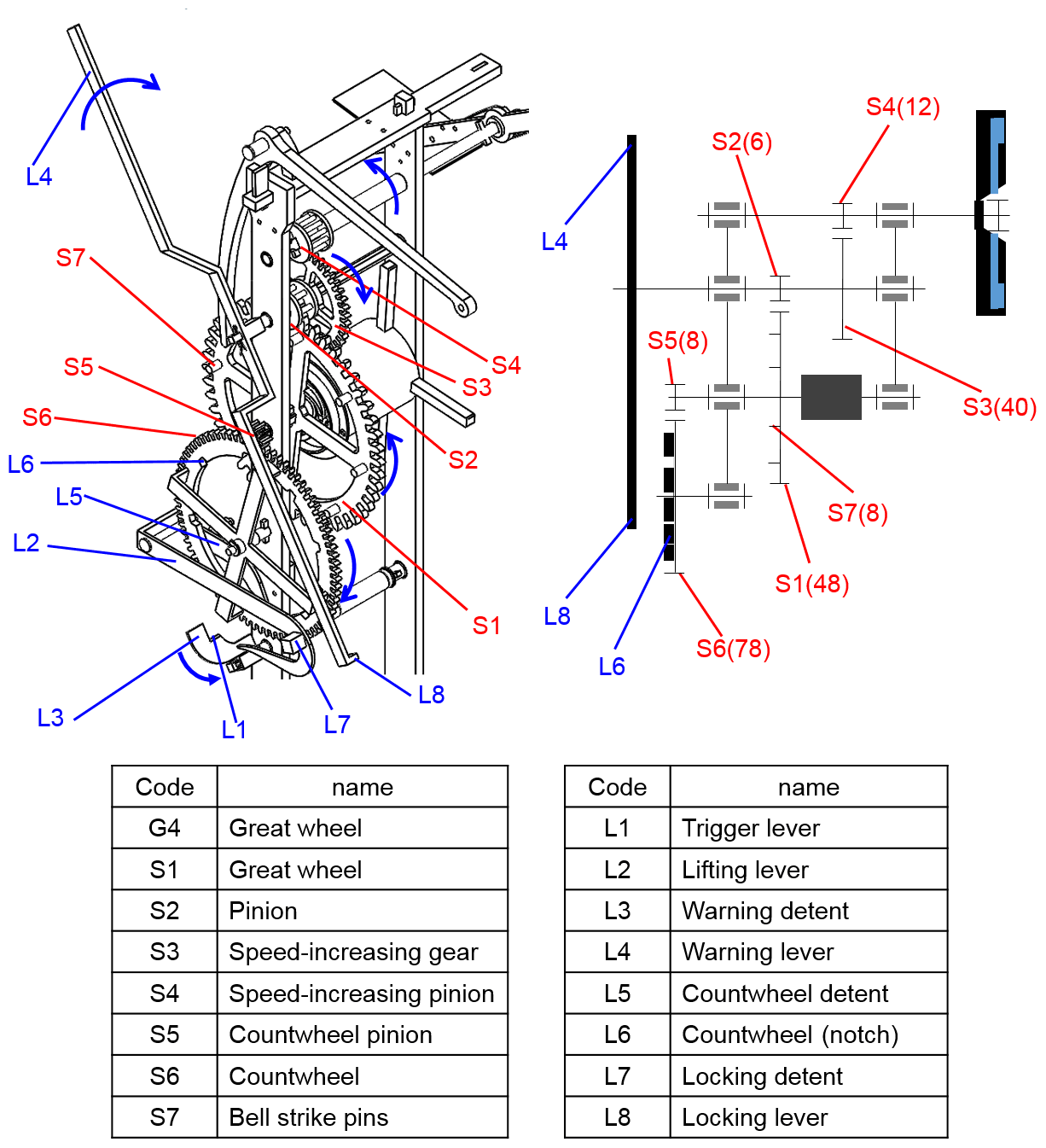
As shown in Fig. 3, the striking trigger mechanism consists of a trigger lever (L1), a lifting lever (L2), a warning detent (L3), a warning lever (L4), a count wheel detent (L5), a count wheel notch (L6), a locking detent (L7), and a locking lever (L8). The L1 lifts the L2 every hour, and the striking train enters the standby state before striking the hour. The analysis of the striking trigger's structure and motion is as follows.
3.2.1 Structure analysis of the striking trigger mechanism
Compared to the structure of the earlier end-to-end mechanical turret clocks, the striking mechanism of the Cotehele clock is an innovative design. As shown in Fig. 3, the trigger lever (L1) moves with the great wheel shaft (G4), and the lifting lever (L2) is installed on the frame to lift L5 and L7 and turn the whole striking gear train. In this design, L5 and L7 are fixed on L2, belonging to the same shaft of L2. L8 is the locking lever, which is installed on the pinion shaft and moves with the whole striking gear train and which actuates the striking gear train by blocking or releasing L7. L3 is the warning detent, which moves with L1 for the accuracy of striking. L4 is the warning lever, which is on the same shaft as L8. The two levers are two ends of a rotating lever, of which the endpoint acts upon L3 to control the starting time of the striking train.
3.2.2 Motion analysis of the striking trigger mechanism
The working process of the Cotehele clock striking train is as follows:
- Step 1.
-
L1 rotates continuously counterclockwise with the great wheel (G4). When it is about to strike the hour, L2 is moved and lifted, and L5 is lifted out of the notch of L6.
- Step 2.
-
L1 continues to rotate counterclockwise. Before striking the hour, L7 releases L8 when it rises to a certain height as L2. At this time, the whole striking gear train is released to rotate freely under the torsion of the weight. Therefore, L8 and L4 rotate clockwise, and L4 is blocked by L3 after rotating about 180∘, at which time the system enters the standby state.
- Step 3.
-
L1 and L3 continue to rotate counterclockwise. Firstly, L1 slides over L2, lowering L2 and L5 until the stop pin of L5 falls on the inner ring of L6. When it is about to strike the hour (on the hour), L4 slides over L3, and the striking train starts to move. At this time, each time L8 performs one revolution, the bell strike pins on the great wheel move the bell strike lever and pull the rope to strike the bell once.
- Step 4.
-
After striking, the stop pin of L5 falls into the notch of L6, while L2 and L7 are at the lowest point. At this time, the clockwise-rotating L8 is blocked by L7, the striking gear train is blocked, and the fly continues to rotate to release kinetic energy until it is still, thus completing the striking procedure.
3.3 Restoration model and experimental test
In this study, restoration design was performed based on the results of historical research, and a restored model of the Cotehele Clock was made to scale. Also shown in Fig. 14a, the geometric and kinematic parameters of the restoration model are shown in Table 2. Based on this model, kinematic and dynamic experimental tests were performed, including (1) finding the minimum weight required to drive the going train, (2) finding the minimum weight required to drive the striking train, and (3) testing the foliot swinging period at different balance weight positions for the foliot and verge escapement regulator.
Table 2Cotehele clock restoration model's geometric and kinematic parameters.
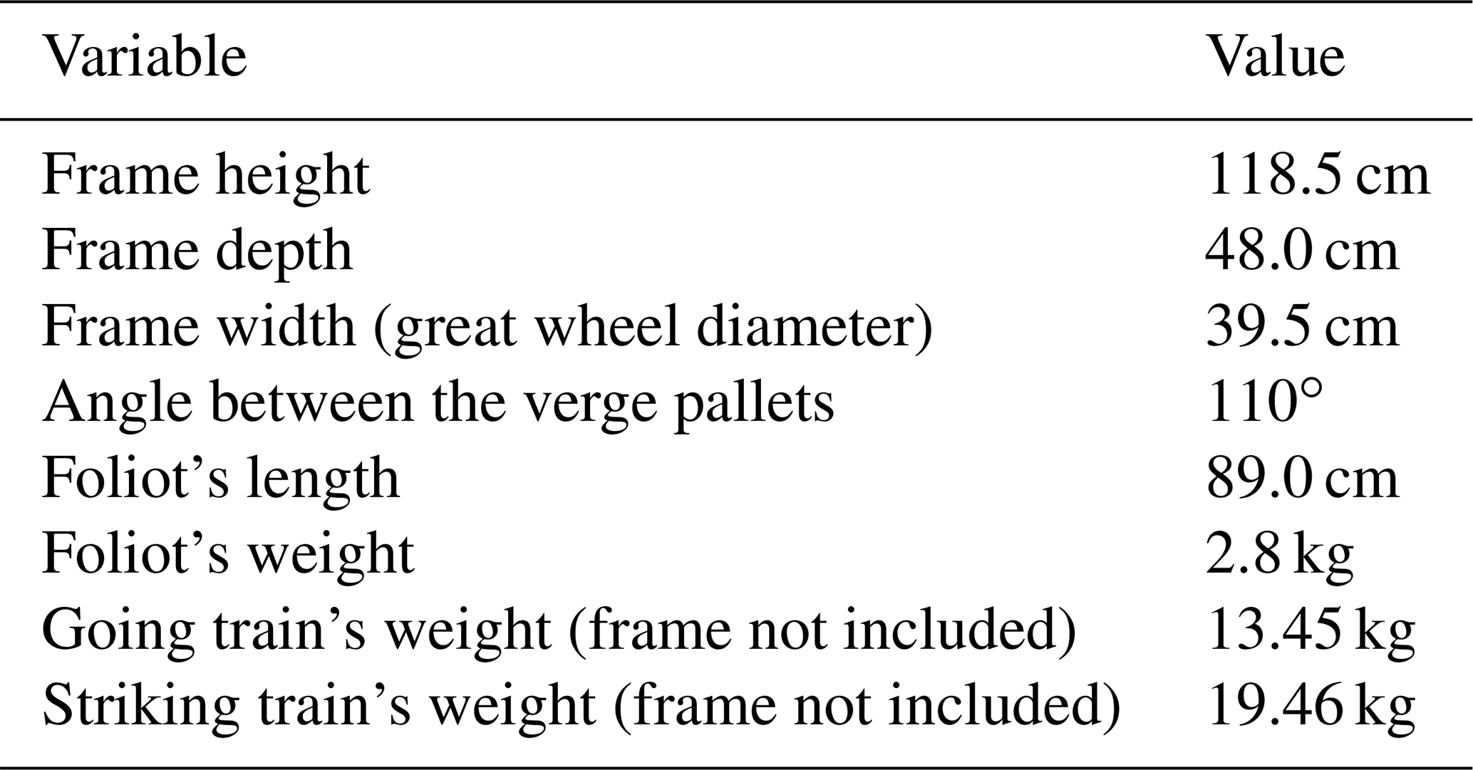
The going train and striking train of this restoration model utilize weights along with fixed pulleys and ropes to drive the power rope wheel. After several experimental tests, the optimal results are shown in Table 3; that is, in addition to the going train system having to overcome the friction generated during motion, it needs to provide the kinetic energy for a swinging motion of the foliot and verge escapement regulator, which requires a minimum weight of 20.85 kg. On the other hand, the striking train system requires a minimum weight of 12.00 kg to steadily start the motion of the striking trigger mechanism and continuously drive the bell hammer as well as to overcome the friction generated during motion.
Table 3Weight required to drive the going train and striking train.
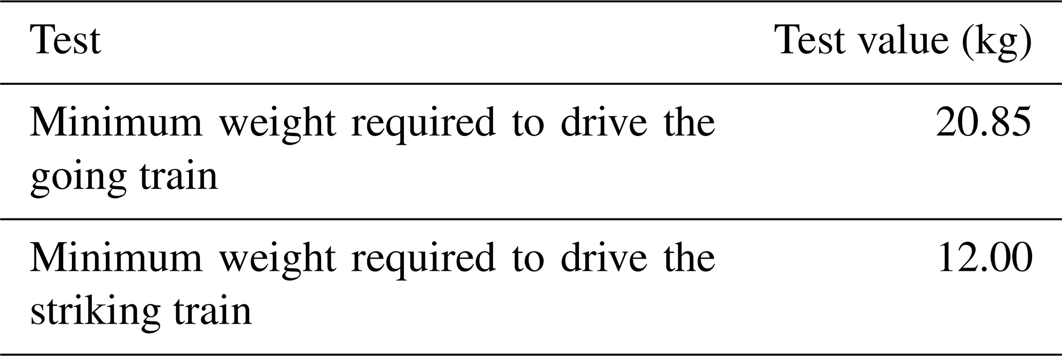
Table 4Parameters used for the foliot swinging period's experimental test.
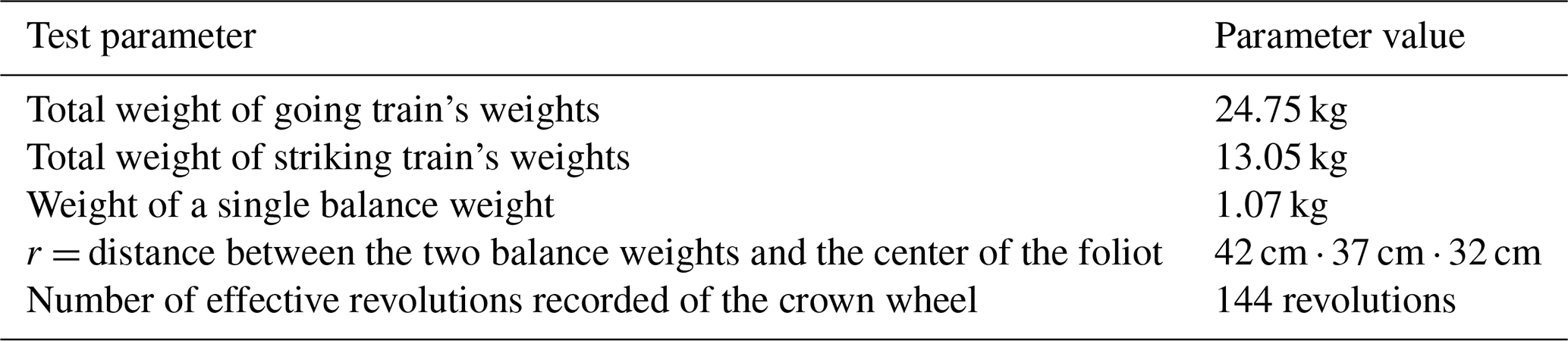
Table 5Foliot swinging period's experimental test and calculation results.
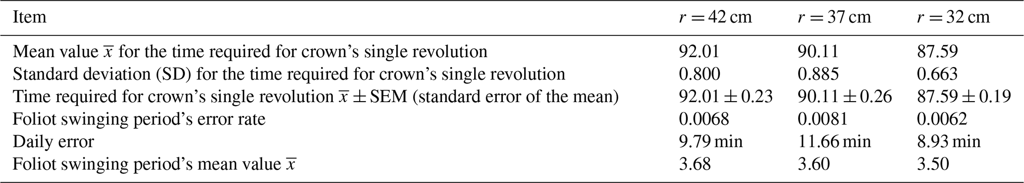
The parameters used for the foliot swinging period's experimental test are shown in Table 4, among which, in order to understand the influence of the distance (r) between the two balance weights' position and the center of the foliot on the swinging period, tests are conducted with the value of r being 42, 37, and 32 cm and the following: (1) the 25 teeth on the crown wheel were marked with numbers from 1 to 25. (2) Using a video camera to record the process of crown wheel's motion, for the purpose of reducing the measurement and observational error, the time for each tooth movement is not recorded; instead the unit of measurement is a revolution of the crown wheel, so the length of the video was used to calculate the data for the time required for the crown wheel to do one revolution, among which for each r position, the value of 144 effective revolutions was recorded. (3) The above data were used to calculate the mean value , standard deviation (SD), and the standard error of the mean (SEM), as shown in Table 5, to finally calculate the error rate of the swinging period for each r value. As shown in Table 5, the daily error is far smaller than the daily error of the foliot and verge escapement regulator of mechanical tower clocks in later history (about 15 min) (James and Jane, 1999); the main difference is that the manufacturing and assembly precision is higher for the restoration model.
From Table 5 it is known that when r = 42 cm, the foliot swinging period (T) is 3.68 s; when r = 37 cm, the foliot's T = 3.60 s; when r = 32 cm, the foliot's T = 3.50 s. Through the method of interpolation, it can be concluded that Δr and ΔT are directly proportional, for which the distance between the balance weights and the center of the foliot (r) can be adjusted to calibrate the foliot's swinging period (T). From the experimental test results shown in Table 5, it can be concluded that this restoration model has good timing accuracy and repeatability. However, there is a considerable gap between its swinging period and T = 12 s obtained in motion analysis in historical research. Therefore, for the improvement of this restoration model without having to change the gear numbers of the going train, the length of the foliot and the value r can be increased, while also reducing the angle between the verge pallets to increase the foliot's swinging range and thus increase the foliot's swinging period.
3.4 Summary
As discussed above, the structures of the going train and the striking train of the Cotehele clock are roughly the same as those of the Salisbury Cathedral clock from 1386. The main difference lies in the changes caused by the different arrangements of trains. For example, the structure of the going train of the Cotehele clock is upside down, and the striking train has a different trigger mechanism structure, as a warning mechanism is added to improve the accuracy of time-telling. The entire trigger mechanism differs from the end-to-end structure, indicating that the structure of the Cotehele clock is the original vertically arranged mechanical turret clock.
According to Table 1, besides the Cotehele clock (N2), there were three other modified mechanical turret clocks in existence during the 15th century. This section describes their original structural types and their modified structures, so as to understand the evolution of the technology. The following is the comparison with Cotehole clock (N2), prioritizing the ones that have less variation, in the order of the Marston Magna clock (N3), the Castle Combe clock (N4), and the Exeter clock (N1).
4.1 Marston Magna clock (N3)
The first clock to discuss is the Marston Magna clock, which was modified in 1710 (Marston Magna, 2018). Only the going train was modified, mainly by changing the foliot and verge escapement regulator into the pendulum and anchor escapement regulator. The structure of its movement remained unchanged. As shown in Fig. 4, like the Cotehele clock, the striking train and the going train are arranged in a vertically arranged fashion. Moreover, the structure and actuation of its striking trigger mechanism are generally the same as those of the Cotehele clock. Therefore, it can be inferred that the original structural type of the Marston Magna clock is similar to that of the Cotehele clock. The existing Marston Magna clock has become one of the new movement structure types of vertically arranged mechanical turret clocks with pendulums. This type of going train is also the main structure of a going train with a pendulum, as shown in Fig. 5. This structure comes from the end-to-end mechanical turret clocks containing a pendulum that was manufactured after 1670, such as the turret clock (1672) made by William Clement (Bennet, 1956).
Because the structure and actuation mode of the Marston Magna clock are similar to those of the Cotehele clock, the rotation speed of the great wheel caused by its going gear train is also one revolution per hour (ωG4 = rpm = rps). Therefore, as shown in Eq. (2), the number of teeth on the going gear train and the swing frequency of the pendulum (ωG1)T can be obtained from the equation of the rotation speed ratio (γ) of its going train, and the swing period is 1/ωG1. For example, in Eq. (2), TG1 indicates that the pendulum swings back and forth once, TG2 is the number of teeth on the escape wheel (30 teeth), TG3 is the number of teeth on the pinion (8 teeth), TG4 is the number of teeth on the great wheel (96 teeth), TG5 is the number of teeth on the second pinion (8 teeth), and TG6 is the number of teeth on the second gear (40 teeth). According to the result of Eq. (2), the cycle of the pendulum swinging back and forth is 2 s.
4.2 Castle Combe clock (N4)
According to historical records, the existing Castle Combe clock was modified after 1670 (Wikipedia, 2019a). As shown in Fig. 6, the going train was replaced by a pendulum and anchor escapement regulator, and the going train and striking train of the clock's movement were reversed, with the former in the upper position and the latter in the lower position. To be specific, in the design modification, the position of the entire movement should be reversed, and other adjustments should be made accordingly. It can be seen that the striking mechanism of L2 (the same lever as L5 and L7) changed the most in its structure. However, it can be inferred that the original structure of the Castle Combe clock was similar to that of the Cotehele clock. In addition, this modified Castle Combe clock provides a design case of the striking trigger, of which the going train is on top of the striking train.
Figure 7Structure of the Exeter clock (N1) (Rabbott, 2015).
4.3 Exeter Cathedral astronomical clock (N1)
The literature states that the Exeter clock (N1) was manufactured around 1484, which is earlier than the Cotehele clock. The structure of the striking train and the striking trigger mechanism of the existing clocks are generally the same as those of the Cotehele clock. As shown in Fig. 7, its original structure was the same as that of the Cotehele clock. However, because the striking train was placed on the side of the going train, the structure of the movement changed greatly, forming the side by side structure. Such structure caused the design problem of L2 movement under the striking trigger lever of the striking trigger mechanism, so there was a great variation of the structure of L2. In addition, the going train was also replaced by a pendulum and anchor escapement regulator, which was also seen in the existing Marston Magna clock (N3) and Castle Combe clock (N4). Therefore, the existing Exeter clock (N1) is a case of a vertically arranged turret clock similar to the Cotehele clock but has evolved into a mechanical turret clock with a side-by-side structure.
4.4 Summary
Based on the above analysis, it can be seen that the structure of the movement for vertically arranged mechanical turret clocks in the 15th century was the same as that of the Cotehele clock. Therefore, this study concludes that the Cotehele clock is the original model of the vertically arranged mechanical turret clock, and the existing Exeter clock (N1), Marston Magna clock (N3), and Castle Combe clock (N4) are three variants of the vertically arranged mechanical turret clocks that evolved from the Cotehele clock.
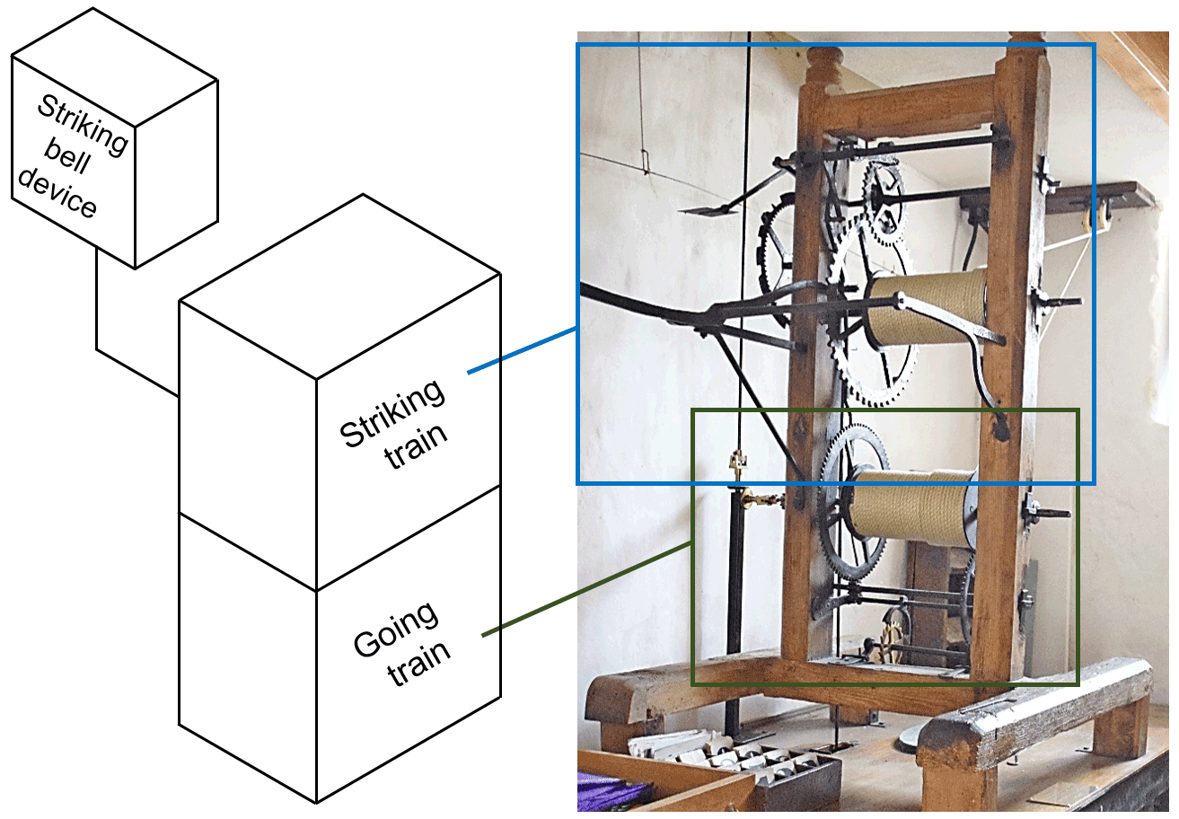
Figure 8Structure of the Metfield clock (N5) (Simon, 2019).
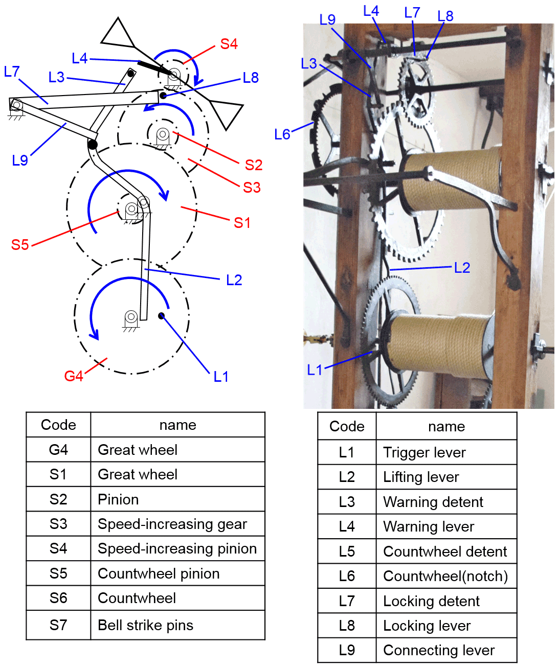
Figure 9Striking train structure of the Metfield clock (N5) (Simon, 2019).
According to the literature, Metfield clock (N5) was manufactured in 1629 and later modified in 1719 (Britain Express, 2021). It is recorded that only the going train was modified, changing the foliot and verge escapement regulator into a pendulum and anchor escapement regulator, while the structure of its movement remained unchanged. As shown in Fig. 8, the original structure was arranged with the striking train being in the upper position and the going train being in the lower position. However, its striking trigger mechanism is different from that of the Cotehele clock, as it adopted the same early end-to-end type striking trigger mechanism as the Salisbury clock and the Cassiobury clock. As shown in Fig. 9, the special feature lies in the design of the starting trigger mechanism of L1 and L2, as well as the warning mechanism of L3 and L4. Therefore, the original Metfield clock (N5) and its striking trigger mechanism constitute the second style of a vertically arranged mechanical turret clock, while the existing Metfield clock (N5) is a variation of the second structure. The structure and actuating steps of its striking train are described as in the following.
5.1 Structure analysis of the striking trigger mechanism
As shown in Fig. 9, a trigger lever (L1) is the start lever on the great wheel, which turns L2 and L3. L2 shares the same lever with L3. L2 and L3 are the two ends of the rotating lever, and two pins are installed in the L3 end. One pin is in the middle (pin 3a) and turns L9, while the other is used as a warning pin opposite to L4. L4 is fixed on the speed-increasing pinion shaft. L5, L7, and L9 are on the same shaft, and L8 is installed on the outer ring of the speed-increasing gear opposite to L7. L5 is matched to the notch of the count wheel and controls the count wheel.
5.2 Motion analysis of the striking trigger mechanism
The working flow of the Metfield clock (N5) striking train is as follows:
- Step 1.
-
L1 rotates counterclockwise with the great wheel and turns L2 when it is about to strike the hour, making L2 and L3 rotate clockwise. L3 simultaneously lifts L9, along with L7 and L5.
- Step 2.
-
L1 continues to rotate counterclockwise. Before striking the hour, L3 turns L9 to separate (lift) L5 from the notch of L6. When L7 rises to a certain height, L8 is released first and followed by the whole striking gear train, which can rotate freely under the torsion of the weight. L4 rotates clockwise before being blocked by L3, and the system then enters the standby state.
- Step 3.
-
L3 and L2 continue to rotate clockwise. On the hour, L1 slides over L2 to reverse L2 and L3, and then L4 slides over L3. At the same time, L5 moves down together with L9 until the stop pin of L5 slides onto the outer ring of L6, and then the striking train starts to move. Each time L8 rotates one revolution, the bell strike pins on the great wheel move the bell strike lever and pull the rope to strike the bell once.
- Step 4.
-
When the striking is over, the stop pin of L5 falls into the notch of L6, and L9 and L7 are lowered and reset to the lowest point. At this time, L8, which rotates counterclockwise, is blocked by L7, so the striking gear train is blocked. The fly continues to rotate and release kinetic energy until it is still, thus completing the striking procedure.
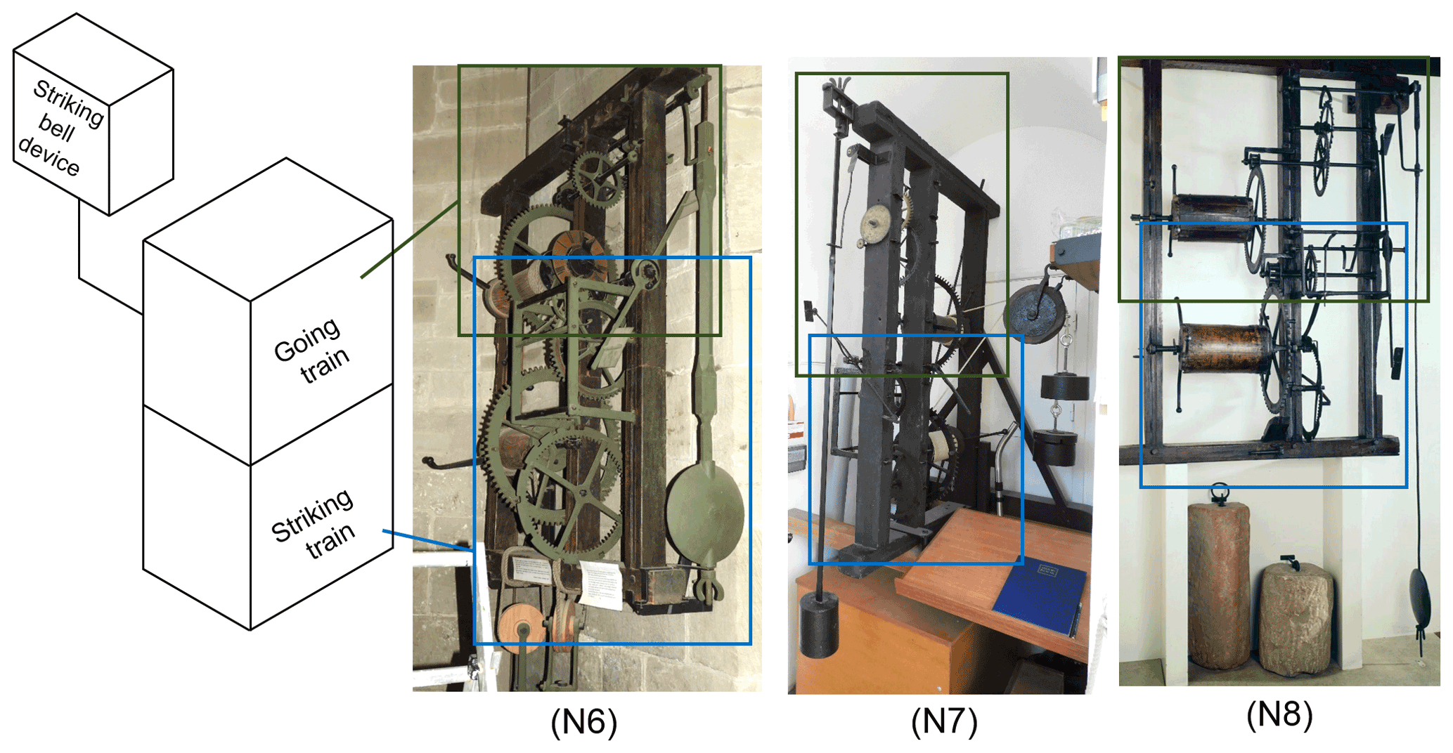
Figure 10The structures of the Kempsey clock (N6) (Chadclocks, 2018a), Worcester clock (N7) (Chadclocks, 2018b), and Martley clock (N8) (Bridgemanimages, 2021).
The existing Kempsey clock (N6), Worcester clock (N7), and Martley clock (N8) have similar movement structures, with the going trains located over the striking trains. Moreover, the going trains are all installed with pendulum and anchor escapement regulators, as shown in Fig. 10. Therefore, they were either manufactured or modified after 1675. The analysis of their structures reveals that the striking trigger mechanism evolved from the second style, as it did in the Metfield clock (N5). However, the structure became simpler and more modular, representing an innovative and commercial design and forming the third style in the development of vertically arranged mechanical turret clocks. In addition, the main difference among these three sets is that the style of L8 for the Kempsey clock (N6) and the Worcester clock (N7) is the hoop wheel, while that for the Martley clock (N8) is the stop pin. L1 of the Kempsey clock (N6) is a shift pin ( rpm) installed on the great wheel (minute hand wheel), while L1 of the Worcester clock (N7) and of N8 is a lever installed on the great wheel shaft ( rpm). The following section describes the structure and actuation steps of the striking train of the Kempsey clock (N6):
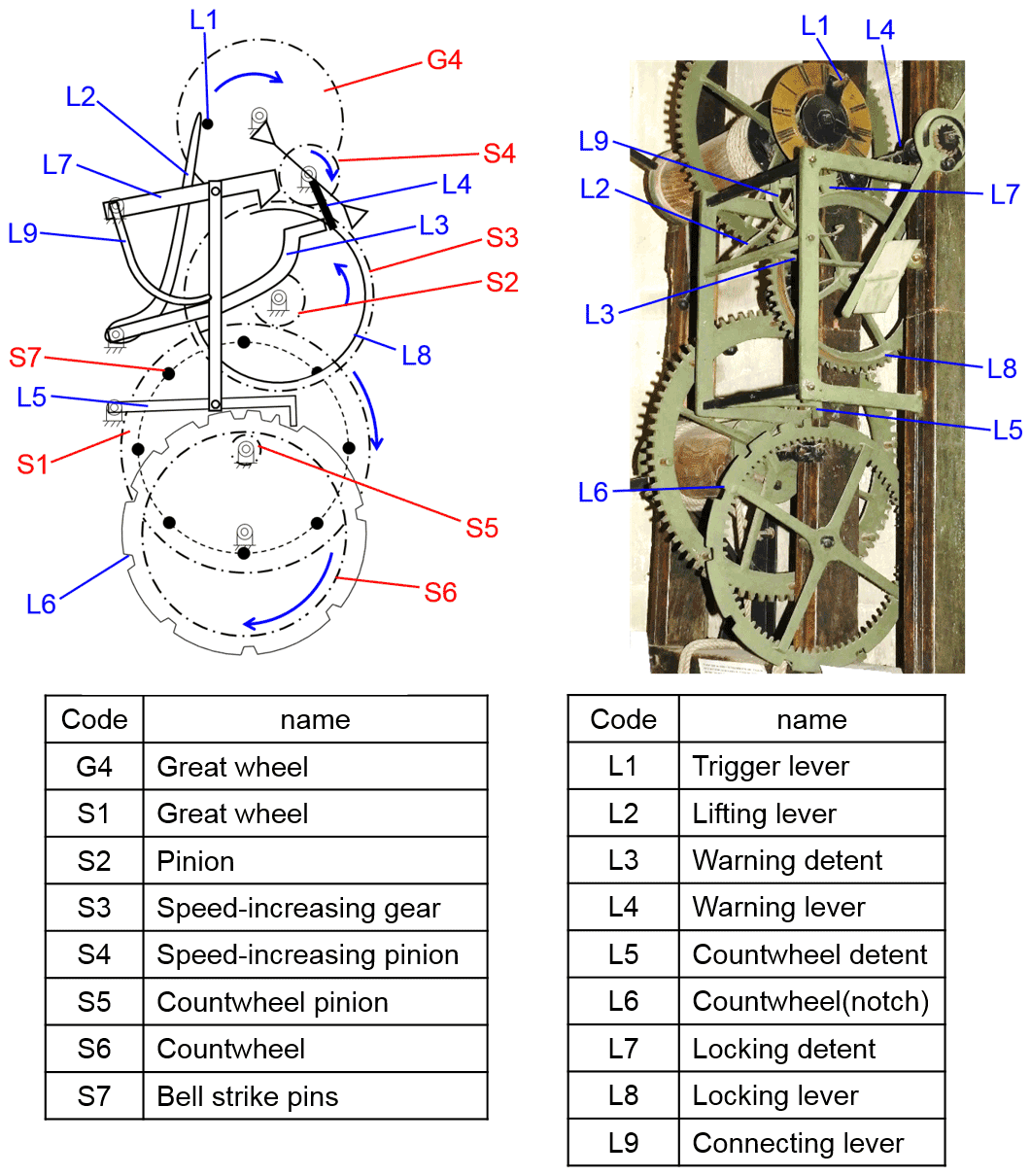
Figure 11Striking train structure of the Kempsey clock (N6) (Chadclocks, 2018a).
6.1 Structure analysis of the striking trigger mechanism
As shown in Fig. 11, L1 is the start lever on the great wheel that turns L2, which shares the same shaft and interlocks with L3. L9, L7, and L5 also interlock with each other, with L9 located on top of L3. L3 can turn and lift L9, and its end is used as a warning pin opposite to L4, which is fixed on the speed-increasing pinion shaft. L8 is an iron ring with a notch installed on the speed-increasing gear opposite to L7, and L5 is designed to work with the notch of the count wheel in order to control the count wheel.
6.2 Motion analysis of the striking trigger mechanism
The working process of the Kempsey clock (N6) striking system is as follows:
- Step 1.
-
L1 rotates clockwise with the great wheel and turns L2 when it is about to strike the hour and causes L2 and L3 to rotate counterclockwise. L3 simultaneously lifts L9, along with L7 and L5.
- Step 2.
-
L1 continues to rotate clockwise and lifts L2. Before striking the hour, L3 lifts L9 to separate L5 from the notch of L6. When L7 rises to a certain height, L8 is released first and followed by the whole striking gear train, which can rotate freely under the torsion of the weight. L4 rotates clockwise until it is blocked by L3, and the system enters a standby state.
- Step 3.
-
L3 and L2 continue to rotate counterclockwise. On the hour, L4 slides over L3 before L1 slides over L2. L2 and L3 then rotate clockwise to reset, lowering L9 and causing the stop pin of L5 to slide onto the outer ring of L6. At the same time, L7 falls on the iron ring of L8 and the striking train starts to move. Each time L8 rotates one revolution, the bell strike pins on the great wheel move the bell strike lever and pull the rope to strike the bell once.
- Step 4.
-
When the striking is over, the stop pin of L5 falls into the notch of L6, and L9 and L7 are lowered and reset to the lowest point. At this time, L8, which rotates counterclockwise, is blocked by L7, so the striking gear train is blocked. The fly continues to rotate and release kinetic energy until it is still, thus completing the striking procedure.
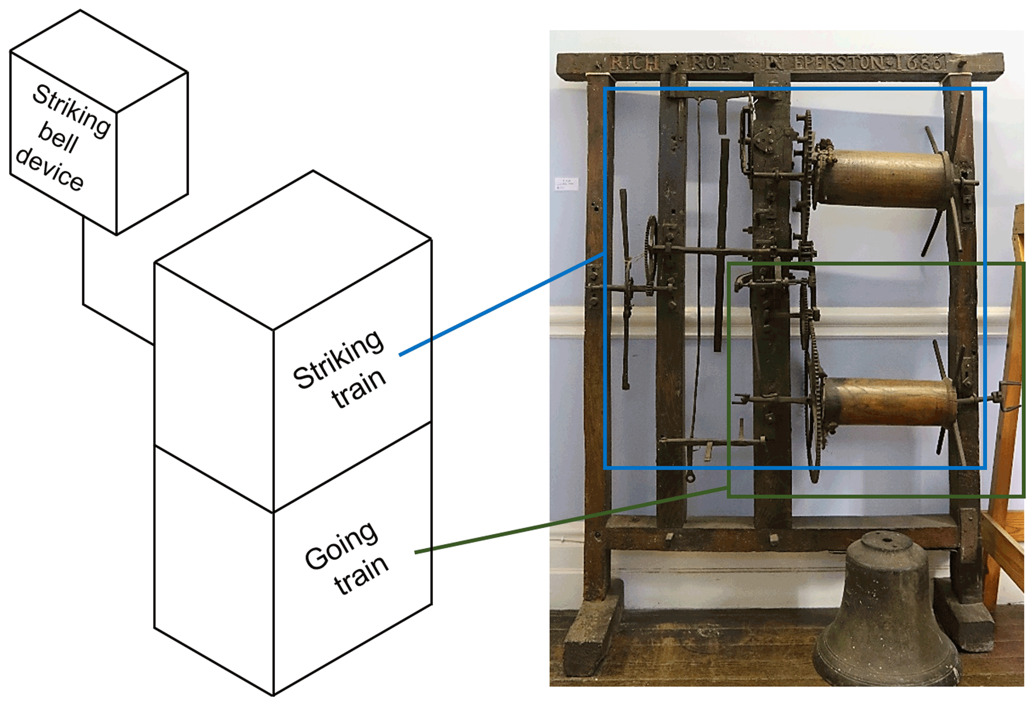
Figure 12Structure of the Plumtree clock (N9) (Rabbott, 2018).
The Plumtree clock (N9) was manufactured in 1686. As observed from the existing object, its going train was installed with a pendulum and anchor escapement regulator, but its movement is a vertically arranged structure with the striking train located on top of the going train, which differs from the third structure that was commonly used, as shown in Fig. 12. Therefore, there was a great variation in its striking trigger mechanism. L1, L4, and L8 were designed based on the first style, while the design of L2 and L3 is similar to the second and third styles. Therefore, the Plumtree clock (N9) and its striking trigger mechanism belong to the fourth style of vertically arranged mechanical turret clocks. The structure and actuation steps of the striking train are described in the following.
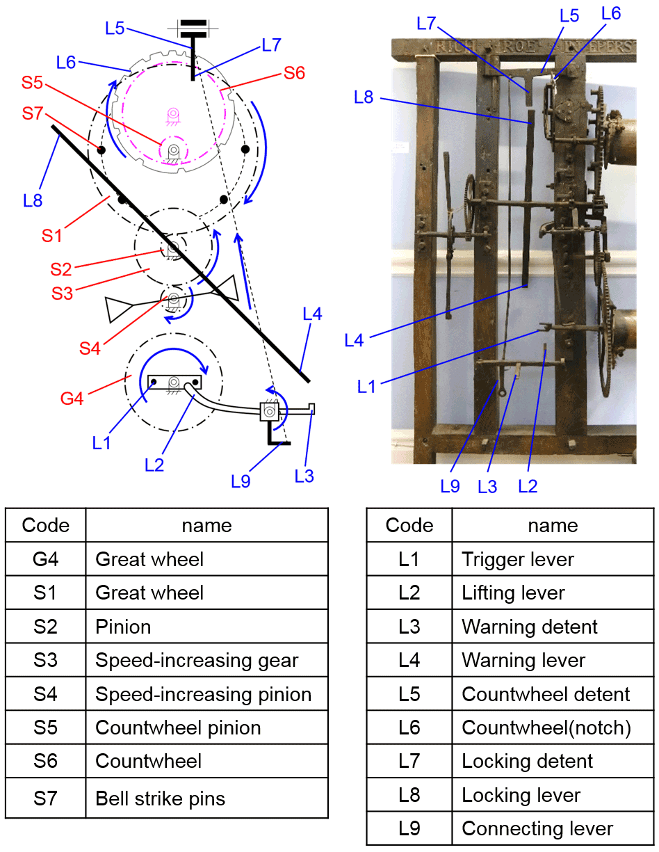
Figure 13Striking train structure of the Plumtree clock (N9) (Rabbott, 2018).
Table 6Restoration of mechanism configurations based on the technology evolution of vertically arranged mechanical turret clocks.
7.1 Structure analysis of the striking trigger mechanism
As shown in Fig. 13, L1 is the start lever ( rpm) and is installed on the great wheel shaft that turns L2, which is co-axial with L3 and L9. L7 and L5 are on the same lever and connect L9 with an iron lever to control its lifting. L8 and L4 are on the two sides of the same rotating lever, respectively. L8 and L7 are opposite to each other and control the actuation of the striking train. L4 is opposite to L3 and is used for standby actuation.
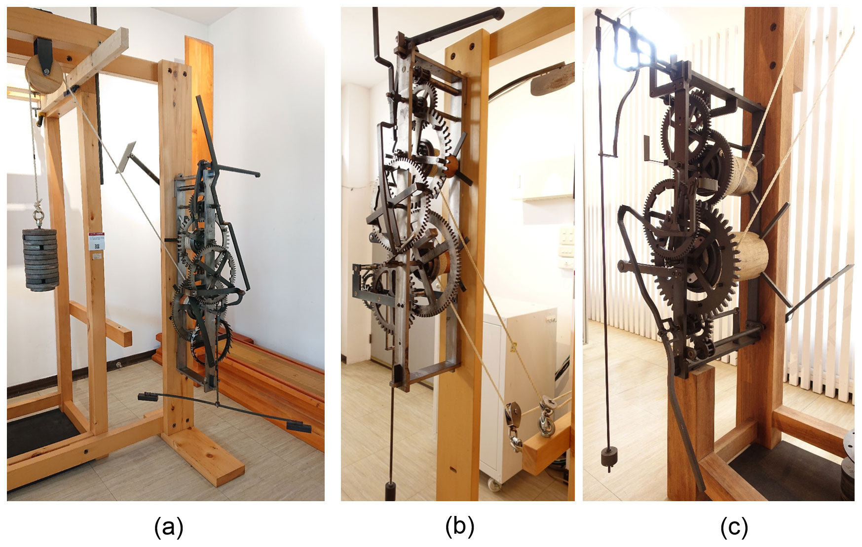
Figure 14Restoration design: (a) Cotehele clock, (b) Marston Magna clock, and (c) Castle Combe clock (photo by Wen-Feng Lin).
7.2 Motion analysis of the striking trigger mechanism
The working process of the Plumtree clock (N9) striking train is as follows:
- Step 1.
-
L1 rotates counterclockwise with the great wheel and turns L2 when it is about to strike the hour, making L2, L3, and L9 rotate clockwise. L9 simultaneously lifts L7 and L5 through the iron lever.
- Step 2.
-
L1 continues to rotate counterclockwise, lifting L2, L3, and L9. Before striking the hour, L5 is lifted out of the notch of L6. When L7 rises to a certain height, L8 is released first and followed by the whole striking gear train, which can rotate freely under the torsion of the weight. L4 (which shares the same shaft with L8) rotates counterclockwise until it is blocked by L3, and the system enters a standby state.
- Step 3.
-
L3 and L2 continue to rotate clockwise. On the hour, L4 slides over L3 and L1 slides over L2. At this time, L2, L3, and L9 are reversed to reset in order to lower L7 and L5 and make the stop pin of L5 slide on the outer ring of L6. The striking train then starts to move. Each time L8 rotates one revolution, the bell strike pins on the great wheel move the bell strike lever and pull the rope to strike the bell once.
- Step 4.
-
When the striking is over, the stop pin of L5 falls into the notch of L6, and L9 and L7 are lowered and reset to the lowest point. At this time, L8, which rotates clockwise, is blocked by L7, so the striking gear train is blocked. The fly continues to rotate and release kinetic energy until it is still, thus completing the striking procedure.
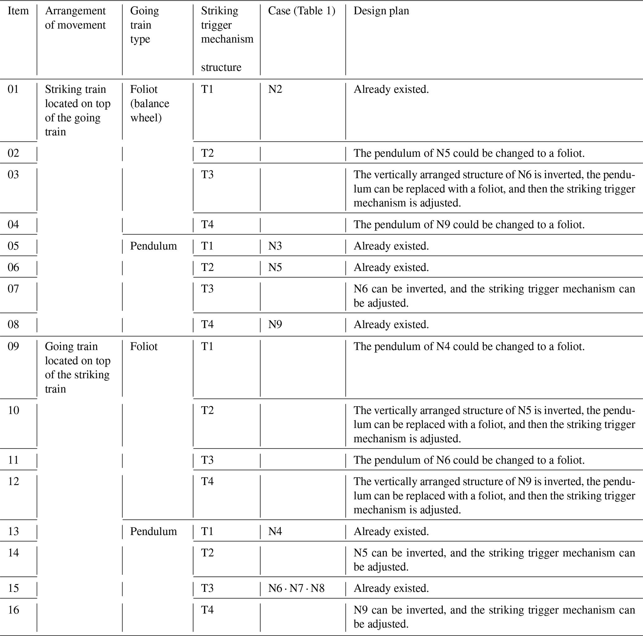
In this section, the restoration design of the mechanism configurations of movements was carried out based on the analysis of the mechanism and structure of the nine vertically arranged mechanical turret clocks listed in Table 1.
-
There are two types of movement arrangements: one in which the striking train is located over the going train and the other one in which the placement is vice versa.
-
There are also two types of going trains: one which uses a foliot (balance wheel), as shown in Fig. 2, and one which uses a pendulum, as shown in Fig. 5. As the balance wheel is a variation of the foliot, it is regarded as being the same type.
-
The striking train is distinguished by the type of striking trigger mechanism used. There are four representative types based on the technology evolution mentioned above, including (a) T1, the striking trigger mechanism of the Cotehele clock (N2), (b) T2, the striking trigger mechanism of the Metfield clock (N5), (c) T3, the striking trigger mechanism of the Kempsey clock (N6), and (d) T4, the striking trigger mechanism of the Plumtree clock (N9).
Besides the vertical arrangement of the going train and striking train, various internal arrangements of the gear trains can be found, which affect the design of the striking trigger mechanism, reflecting the different types of striking trigger mechanisms. Therefore, the arrangement of the internal gear trains was not included in the variables of this restoration design. While theoretically, there should be many types of striking trigger mechanisms, most of the movement structures in history actually evolved from relevant technology. Therefore, in this study, the movement structures were arranged according to the three parameter changes mentioned above, resulting in 16 (2 × 2 × 4) representative restorations of the mechanism configurations of movements of vertically arranged mechanical turret clocks, as shown in Table 6. Among them, item no. 01 is the earliest style of vertically arranged mechanical turret clocks, while item no. 12 is a mature structure, serving as the main style of vertically arranged mechanical turret clocks with pendulums in the 17th century.
Finally, based on the results on this study, restored models of three vertically arranged mechanical turret clocks, namely the Cotehele clock (N2), the Marston Magna clock (N3), and the Castle Combe clock (N4), were manufactured, as shown in Fig. 14.
This study analyzed the mechanisms of nine existing European vertically arranged mechanical turret clocks manufactured from the 15th to the 17th century and found four main movement structures and restorations of 16 representative mechanism configurations of movements based on the evolution of the technology, from which restored models of three vertically arranged mechanical turret clocks, namely the Cotehele clock (N2), the Marston Magna clock (N3), and the Castle Combe clock (N4), were manufactured. The innovative findings can provide references to the structural evolution of vertically arranged mechanical turret clocks in different periods of history, their restoration research, and for researchers of science and technology history.
The structure of vertically arranged mechanical turret clocks is unique and of aesthetic value, especially for the four existing clocks of the 15th century. This study explored the evolution of technology, from the original structure of the Cotehele clock (N2) to the structures of the Marston Magna clock (N3), the Castle Combe clock (N4), and the Exeter Cathedral astronomical clock (N1). The continuous modification and innovation of the new technologies to pursue more accurate timekeeping can inspire teaching plans for contemporary science education and enrich learners' historical and scientific knowledge.
The data are available upon request from the corresponding author.
WFL was responsible for collecting the research literature, organizing the paper structure, and writing the paper. TYL provided the research direction of this paper, together with suggestions for the revision and correction of the paper.
The contact author has declared that neither of the authors has any competing interests.
Publisher's note: Copernicus Publications remains neutral with regard to jurisdictional claims in published maps and institutional affiliations.
The authors are grateful to the Ministry of Science and Technology (Taiwan, ROC; grant no. NSC 100-2221-E-006-065-MY3) for their support of this work.
This research has been supported by the Ministry of Science and Technology, Taiwan (grant no. NSC 100-2221-E-006-065-MY3).
This paper was edited by Daniel Condurache and reviewed by two anonymous referees.
Bennet, G. W.: A Turret Clock by William Clement, Horological Journal, 98, 348–349, 1956.
Bridgemanimages: https://www.bridgemanimages.com/en/noartistknown/clocks-public-wood-framed-turret-clock-horloge-tourelle-english-c-1680/object/asset/5061604, last access: 9 May 2021.
Britain Express: https://www.britainexpress.com/counties/suffolk/churches/metfield.htm, last access: 17 February 2021.
Britten, F. J.: Old Clocks and Watches & their Makers, E. & F. N. Spon, Ltd, London, 37–38, 1922.
Bybrook Benefice: https://bybrook.org.uk/our-churches/castle-combe/, last access: 19 October 2021.
Chadclocks: Photo for the album “2018 Worcester”, Flickr, https://www.flickr.com/photos/22415137@N08/43673944851 (last access: 9 September 2019), 2018a.
Chadclocks: Photo for the album “2018 Worcester”, Flickr, https://www.flickr.com/photos/22415137@N08/29803643158 (last access: 9 September 2019), 2018b.
Exeter Cathedral: https://www.exeter-cathedral.org.uk/history-heritage/, last access: 12 December 2021.
Frank, M.: The Evolution Of Tower Clock Movements And Their Design Over The Past 1000 years, 11–12, MY-TIME-MACHINES, http://www.my-time-machines.net/speech_final_web.pdf (last access: 9 September 2015), 2013.
James, J. and Jane, F. R.: From Sundials to Atomic Clocks Understanding Time and Frequency, U.S. Government Printing Office, Washington, DC 20402, 36–37, ISBN 9780160500107, 1999.
Liang, Z. J. and Liang, S.: A New Angle of View in Machinery History Studies – Drawing Up Evolution Pedigree and Innovation, Proceedings of 2000 HMM International Symposium on History of Machines and Mechanisms, edited by: Ceccarelli, M., Springer, Switzerland, 283–290, https://doi.org/10.1007/978-94-015-9554-4_32, 2000.
Lin, T. Y.: SHUIYUN SHIZHUAN—ZHONGGUO GUDAI QINZONG TIAOSUQI ZHI XITONGHUA FUYUAN SHEJI, edited by: Zhang, B. C., Shandong Education Press, Jinan, China, 3–6, ISBN 9787570109678, 2020.
Marston Magna: http://web.archive.org/web/20150214091900/http://marstonmagnachurch.org/History.html, last access: 9 September 2018.
McKay, C. G.: The Turret Clock Keeper's Handbook, Antiquarian Horological Society, London, UK, 27–28, ISBN 9781492317708, 1998.
Metfield: https://metfieldsuffolk.com/church/, last access: 19 November 2021.
National Trust Collections: https://www.nationaltrustcollections.org.uk/place/cotehele, last access: 25 October 2020a.
National Trust Collections: https://www.nationaltrustcollections.org.uk/object/347888, last access: 25 October 2020b.
Rabbott, A.: Photo for the file “Early mechanism for the Exeter Cathedral astronomical clock 01.jpg”, Wikipedia, https://en.wikipedia.org/wiki/File:Early_mechanism_for_the_Exeter_Cathedral_astronomical_clock_01.jpg (last access: 15 May 2021), 2015.
Rabbott, A.: Photo for the file “Door Frame Clock by Richard Roe of 1686 01.jpg”, Wikipedia, https://en.wikipedia.org/wiki/File:Door_Frame_Clock_by_Richard_Roe_of_1686_01.jpg (last access: 15 May 2021), 2018.
Severnside Parishes: http://www.severnsideparishes.co.uk/index.php/churches/st-mary-kempsey/history, last access: 19 November 2021.
Simon, K.: Photo for the album “Metfield”, Flickr, https://www.flickr.com/photos/norfolkodyssey/40640190723, last access: 9 September 2019.
Southwell & Nottingham Church History Project: https://southwellchurches.nottingham.ac.uk/plumtree/hintro.php, last access: 19 November 2021.
St Martin In The Cornmarket: https://stmartininthecornmarket.co.uk/index.php/about-us/, last access: 19 November 2021.
Wikipedia: https://en.wikipedia.org/wiki/Cotehele_clock, last access: 9 November 2016.
Wikipedia: https://en.wikipedia.org/wiki/Castle_Combe_Clock, last access: 9 January 2019a.
Wikipedia: https://en.wikipedia.org/wiki/Richard_Roe_(clockmaker), last access: 23 November 2019b.
Wikipedia: https://en.wikipedia.org/wiki/St_Mary's_Church,_Marston_Magna, last access: 19 October 2021.
Worcestershire & Dudley: https://www.worcesteranddudleyhistoricchurches.org.uk/application-form-church-history/places/martley, last access: 9 November 2021.
Yan, H. S.: An Approach for the Reconstruction Synthesis of Lost Ancient Chinese Mechanisms, Proceedings of 2008 HMM International Symposium on History of Machines and Mechanisms, edited by: Yan, H. S. and Ceccarelli, M., Springer, Switzerland, 325–336, https://doi.org/10.1007/978-1-4020-9485-9_23, 2009.
- Abstract
- Introduction (motives and purposes)
- Research limitations and sampling
- The first style of a vertically arranged mechanical turret clock
- The main structures of vertically arranged mechanical turret clocks in the 15th century
- The second style of a vertically arranged mechanical turret clock – Metfield clock (N5)
- The third style of a vertically arranged mechanical turret clock – Kempsey clock (N6)
- The fourth style of a vertically arranged mechanical turret clock – Plumtree clock (N9)
- Restoration of the mechanism configurations of movements
- Conclusions
- Data availability
- Author contributions
- Competing interests
- Disclaimer
- Acknowledgements
- Financial support
- Review statement
- References