the Creative Commons Attribution 4.0 License.
the Creative Commons Attribution 4.0 License.
 | 16 Feb 2022
A new type of auxiliary structure for tunnel-surrounding rock support – composite cantilever support structure
Jun Qu
Shixin Bai
Yazhe Li
The deformation and damage mechanisms of tunnel-surrounding rock masses have always been a major problem in underground engineering, and studying these mechanisms plays an important role in preventing this kind of geological disaster. Against the background of the above project, in this paper, we propose a new type of support structure: a composite cantilever support structure. Studies involving the numerical calculation and application of this support structure are carried out, and the conducted investigation indicates that (1) for a relatively broken rock mass, the composite cantilever support structure can effectively restrain the deformation of the tunnel-surrounding rock mass, (2) through numerical calculation, the appropriate design parameters of the support structure are obtained, and (3) the design parameters and design structure of the composite cantilever support structure must be further studied and verified under complex geological conditions by engineering.
- Article
(8640 KB) - Full-text XML
- BibTeX
- EndNote


Serious tunnel deformation poses a great threat to engineering construction projects, such as the Huinashan highway tunnel in Japan, the Tauern tunnel in Austria, and the Arlberg tunnel, which are typical examples of tunnel-surrounding rock deformation (Kimura et al., 1987; Weidinger and Lauffer, 2009; Xue et al., 2019). Deformation of tunnel-surrounding rock has been a major problem in underground engineering for a long time (Wu et al., 2015; Liu et al., 2014; Wang, 2010; Wu and Zhu, 2012).
During the excavation, the tunnel-surrounding rock begins to move towards the tunnel, which is called convergence (Brown et al., 1983; Lin et al., 2005). If the strength of the rock mass is high and the section shape is favourable, when the deformation of the rock mass develops to a certain extent, it will stop by itself, and the surrounding rock will be stable. In contrast, the deformation of the surrounding rock will freely develop and cause the overall instability and failure of the surrounding rock mass (Huo, 2006). It is assumed that at the same time of excavation, the supporting structure will be immediately constructed. When the support structure has great rigidity, the surrounding rock may not deform, but the support structure must keep the surrounding rock in the original initial stress state. So, the reaction force of the support structure must be equal to the total pressure formed by the initial stress in the surrounding rock (Li and Xu, 2013). In contrast, if the supporting structure is set too late or if the rigidity is too low, the surrounding rock structure will relax, the self-supporting capacity will decrease, and the required supporting resistance of the supporting structure will increase.
To ensure the stability of the tunnel-surrounding rock, it is necessary to adopt reasonable support and reinforcement methods to improve the mechanical properties of the surrounding rock and to satisfy the stability requirements of the support structure. The support structure is mainly divided into active support and passive support (Panet and Guenot, 1983; Varljen et al., 1977; Niu et al., 2015; Sun et al., 2015). Passive support is mainly composed of the support material, which passively bears the relaxation and deformation pressure caused by crustal stress and surrounding rock expansion. After failure, the surrounding rock acts as a load on the support structure, which cannot exhibit its own bearing capacity, and the mechanical properties and failure processes of the rock mass after damage play a decisive role in the stability of the supporting structure (Qing et al., 2007; Li et al., 2011). Active support refers to the use of bolts, shotcretes, metal meshes, grouting, and other methods or different combinations of support methods. Active support can largely improve the bearing capacity of the surrounding rock (Li et al., 2010; Yang et al., 2014; Li et al., 2011; Huang et al., 2013).
Scholars have performed substantial work on the deformation and support methods of tunnel-surrounding rock and have introduced new support theories and support systems from different perspectives, but many deficiencies remain (Wu et al., 2018; Guo et al., 2014; Zheng et al., 2015; Yang et al., 2015; Guo et al., 2015; Oreste, 2003). Based on numerical calculation and engineering practice, this paper proposes a new supporting structure that can effectively restrain the deformation trend of the obvious expansion of the surrounding rock during the construction process.
The paper is organized as follows. Section 2 briefly introduces the composite cantilever support structure, which is compared with the bolt support method by numerical calculation and application research. Section 3 discusses the experimental results, analysis, and evaluation of the application effect of the composite cantilever support structure. Section 4 draws the conclusions.
2.1 Overview
In this section, the composite cantilever support structure is discussed and compared with the anchor bolt. Numerical experiments are designed for the composite cantilever support structure. Finally, the support structure is applied to the surrounding rock support of a highway tunnel.
2.2 Composite cantilever support structure
The composite cantilever support structure includes the seamless steel pipe (108 mm-diameter steel pipe is used in this paper) and the bored pipe staggered at the arch waist of the tunnel, one end of which is fixed on the arch frame with a grouting port reserved and the other end inserted into the surrounding rock. The composite cantilever support structure is shown in Fig. 1.
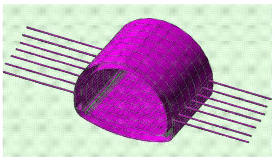
During the construction of the support structure, the seamless steel pipe is inserted into the steel bar and filled with cement mortar. Cement slurry is injected into the bored pipe to grout the surrounding rock of the tunnel. The other ends of the seamless steel pipe and bored pipe are fixed on the arch frame, and concrete is sprayed along the inner wall of the tunnel to form the initial lining of the tunnel.
In tunnel construction, the bench method is often used to excavate, and the tunnel excavation section is divided into two parts. The calculation model and examples in this paper assume that this construction method is used.
The mechanism of the composite cantilever support structure is as follows.
-
The surrounding rock is strengthened, the fissure water of the rock is blocked, and the deformation as well as settlement of the arch are reduced.
-
After the upper stage is completed, it becomes an elastic foundation beam structure on both sides of the initial support, which can bear three stress modes, namely, tension, compression, and bending, to prevent the large deformation caused by the excavation of the lower stage.
-
By sharing the surrounding rock load caused by the excavation of the upper steps, the disadvantage of the insufficient bearing capacity of the initial soft foundation soaked by groundwater is solved.
2.3 Calculation and analysis of the composite cantilever support structure
The finite-element method software is used to analyze the effects of the length and insertion angle of the composite cantilever on the displacement and internal force of the tunnel structure. The model is based on the Mohr–Coulomb constitutive model; the surrounding rock is assumed to conform to the elastic–plastic constitutive relationship and fixes the horizontal displacement on both sides of the model and the vertical displacement at the bottom, as shown in Fig. 2.
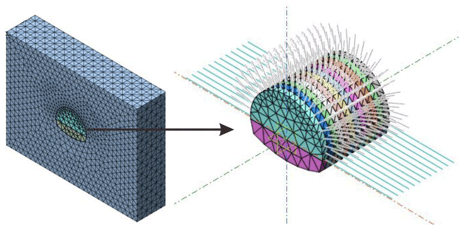
Figure 2Three-dimensional finite-element analysis model of the composite cantilever support structure.
The model boundary is 3-D far from the side and bottom of the tunnel (D is the tunnel span), and the average buried depth from the upper part of the tunnel to the surface is 10 m. In numerical simulation, a two-dimensional model uses the beam element to simulate shotcrete and the truss element to simulate the bolt and steel tube; a three-dimensional model uses the plate element to simulate shotcrete and the embedded truss element to simulate the bolt and steel tube.
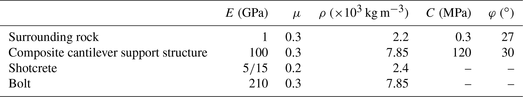
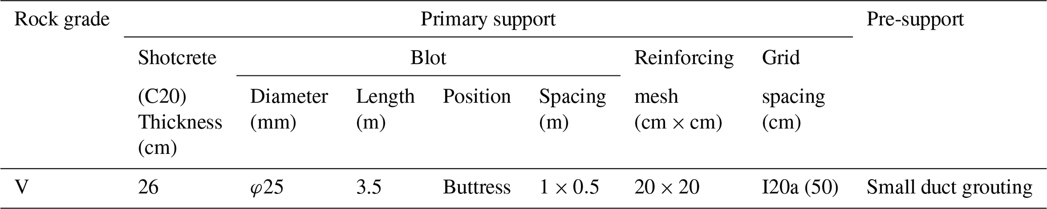
2.3.1 Parameters of the surrounding rock and support structure
The parameters of the surrounding rock and support structure are shown in Table 1.
2.3.2 The influence of the cantilever length on the support effect
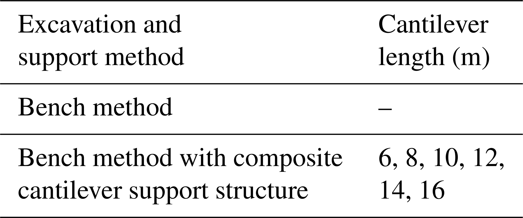
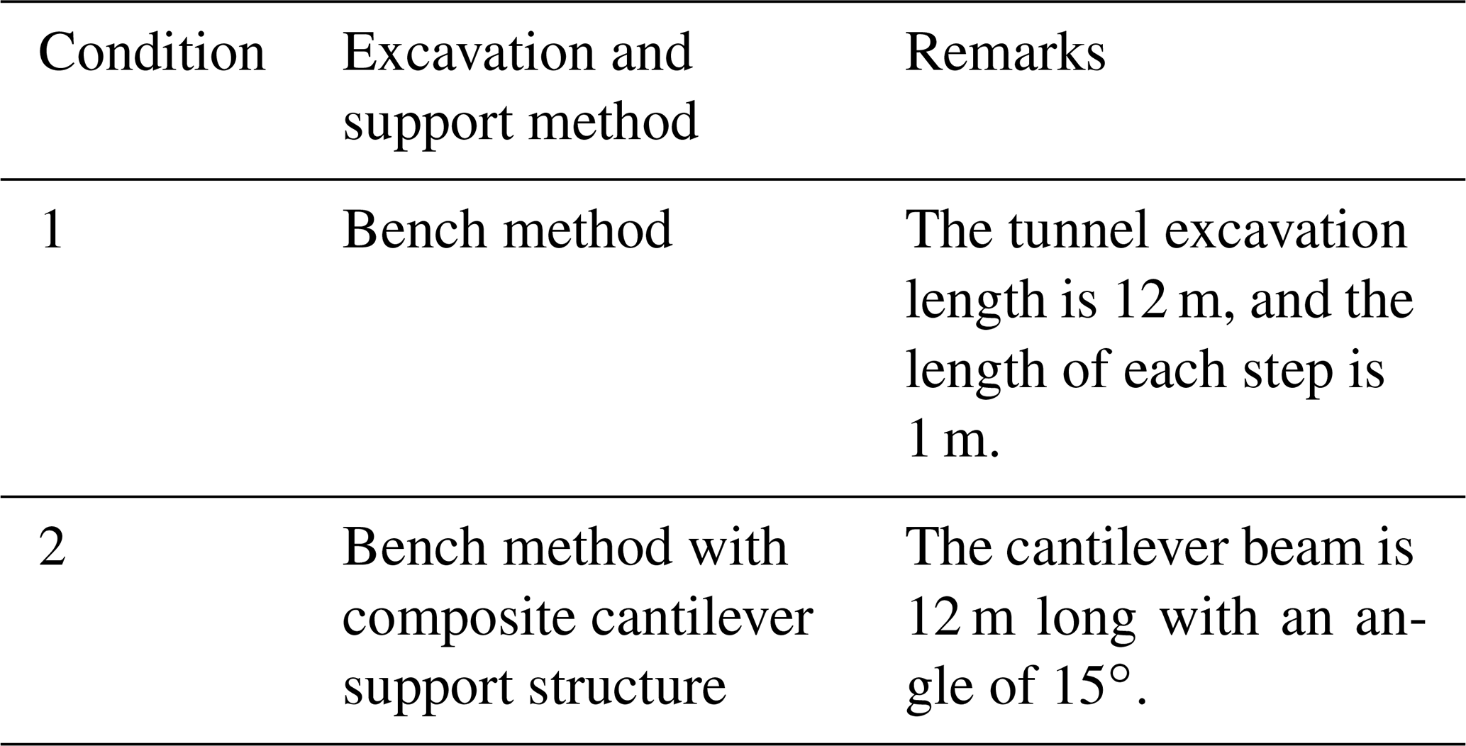
The tunnel model adopts two construction methods: the normal bench method and the bench method with the composite cantilever support structure. Effects of different cantilever lengths on the displacement and internal force of the tunnel support structure are analyzed by changing the length of the cantilever beam. The insertion angle of the cantilever beam is 15∘, and there are seven kinds of specific working conditions shown in Table 2.
2.3.3 The influence of the cantilever angle on the support effect
To analyze the influence of the cantilever angle on the support effect, the model of Condition 6 in Table 2 is used for analysis. We set the angle of the cantilever beam to 0, 5, 10, 20, 25, and 30∘ and carry out numerical simulation. The numerical simulation results of six working conditions are compared with that of the insertion angle of 15∘.
2.3.4 The deformation effect of the surrounding rock and support structure of the tunnel analysis
Through the above analysis, the selection of the parameters is optimized. We further establish the three-dimensional finite-element model of the tunnel and analyze the influence of the composite cantilever support structure on the deformation of the surrounding rock and support structure of the tunnel. See Table 3 for the working conditions.
2.4 Application effect analysis
Fifty meters of the left line (comparison section) and right line (test section) of a highway tunnel (Fig. 3) were selected for study. The test section and comparison section have similar geological conditions. The terrain of the entrance is steep with an aspect of 275–280∘ and a slope of 35–50∘. The intersection angle between the terrain contour line and the tunnel axis of the left line is approximately 65∘, and the intersection angle with the right line is approximately 40∘. There is no surface water flow, and the slope stability is good. The Quaternary overburden near the portal and total strong weathering layer of the rock are very thick; they are mainly composed of cohesive soil or gravelly soil. Affected by faults, tunnel excavation easily collapses after excavation.
The lithology is Devonian metasandstone, phyllite, etc., and the occurrence of the rock stratum is 158∘ ∠ 50∘. There are two groups of main joints: (1) 130∘ ∠ 80∘ and (2) 350∘ ∠ 50∘. The completely, strongly weathered rock is very thick. The left- and right-hand side slopes of the tunnel portal are mainly soil or similar soil slopes with poor stability.
The same original design support (Table 4) is used for the test section and comparison section, and the composite cantilever support structure is added for the test section.

The survey points are arranged 5 m after entering the tunnel, and the monitoring section spacing is 10 m. After blasting, the survey points will be arranged in time, and the initial reading will be obtained within 6 h.
3.1 Numerical experiment results
3.1.1 Analysis of the influence of the cantilever length on the supporting structure
The model calculation results of Conditions 1, 4, and 7 are typical, as shown in Figs. 4–6.
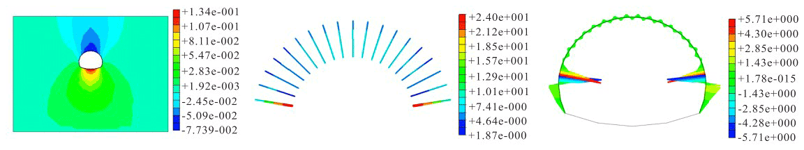
Figure 4Working Condition 1: vertical displacement of the surrounding rock (mm), moment of shotcrete (KN m), and axial force of the anchor rod (KN).
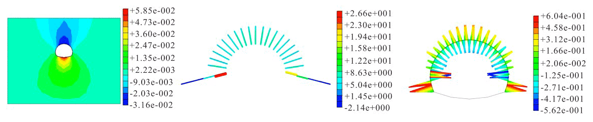
Figure 5Working Condition 4: vertical displacement of the surrounding rock (mm), moment of shotcrete (KN m), and axial force of the anchor rod and cantilever beam (KN).
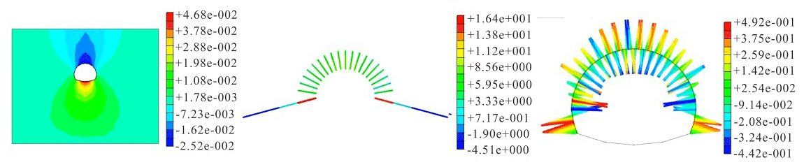
Figure 6Working Condition 7: vertical displacement of the surrounding rock (mm), moment of shotcrete (KN m), and axial force of the bolt and cantilever beam (KN).
The numerical results are shown in Table 5.
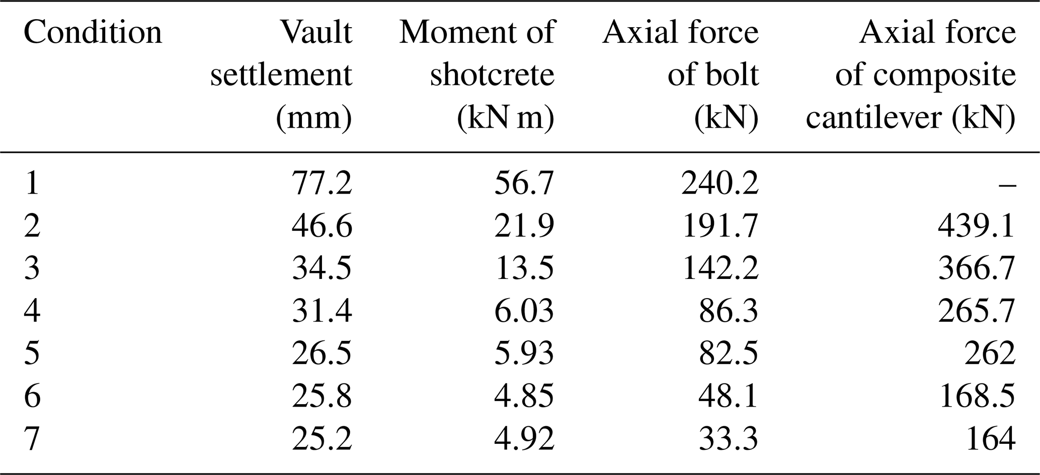
The chart shows that the settlement of the vault can be significantly reduced by the composite cantilever beam. In Condition 1, without the reinforcement of the composite cantilever beam, after a section excavation of the tunnel is completed, the vault subsidence is 10.6 mm, and the floor exhibits an obvious bulging deformation. The settlement is 7–12 mm, which indicates that the tunnel has a large deformation. In Conditions 2–7, the tunnel is set with different lengths of the composite cantilever beam. We can see that with the increase in the length of the cantilever beam, the internal forces of the vault subsidence, the surrounding rock, and the supporting structure gradually decrease, which shows that the deformation of the surrounding rock is well controlled by adopting the new support technology. In addition, when the length of the cantilever beam increases to 12 m, the structural displacement and internal force only slightly decrease. Through calculation and analysis, the curve of the relationship among the length of the cantilever beam, the settlement of the arch crown, and the internal force of the support structure are obtained, as shown in Figs. 7–8.
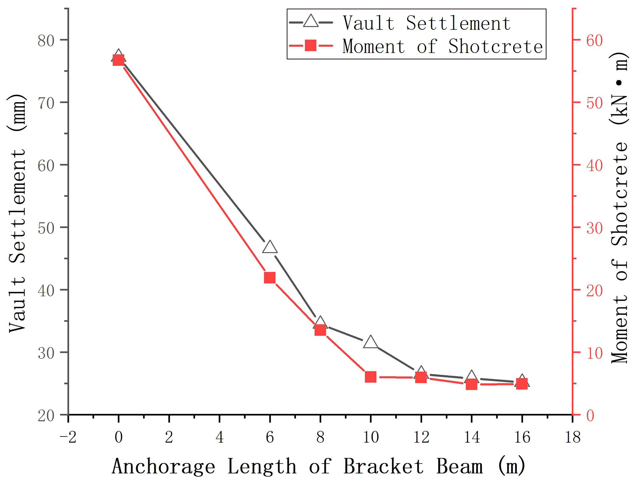
Figure 7Relation curve of the cantilever beam length with vault settlement and moment of shotcrete.
According to the numerical simulation results, with the increase in length of the cantilever beam, the settlement of the vault gradually decreases. It is suitable for selecting a cantilever beam with a length of 10–12 m, which is equal to the tunnel diameter.

Figure 8Relation curve of the cantilever beam length with the axial force of the cantilever beam and the axial force of the composite cantilever.
3.1.2 Analysis of the influence of the cantilever angle on the supporting structure
The numerical simulation results of each working condition are shown in Fig. 9.
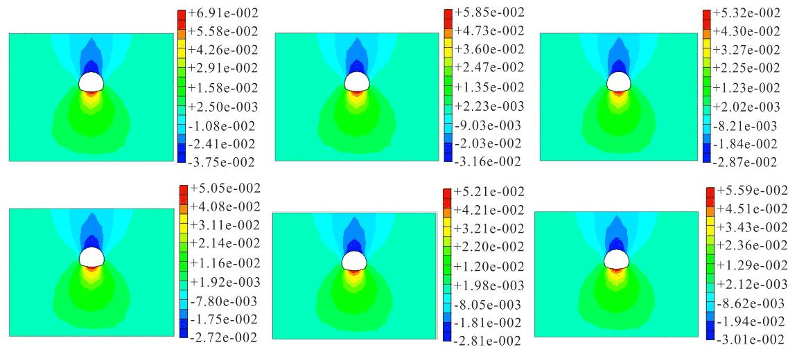
The numerical results are shown in Table 6.
The relationship curve between the angle of the cantilever beam and the settlement of the vault is obtained, as shown in Fig. 10.
Figure 10Relation curve of the cantilever beam angle and vertical displacement of the vault.
According to the chart, with the increase in the angle of the cantilever beam, the vertical settlement of the vault gradually decreases. When the angle of the cantilever beam is greater than 15∘, the settlement of the vault begins to minimally change, so the angle of the cantilever beam should be 15–20∘.
3.1.3 Analysis of the surrounding rock and supporting deformation of the tunnel
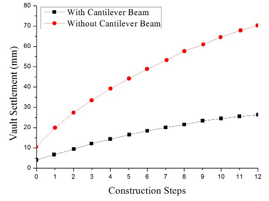
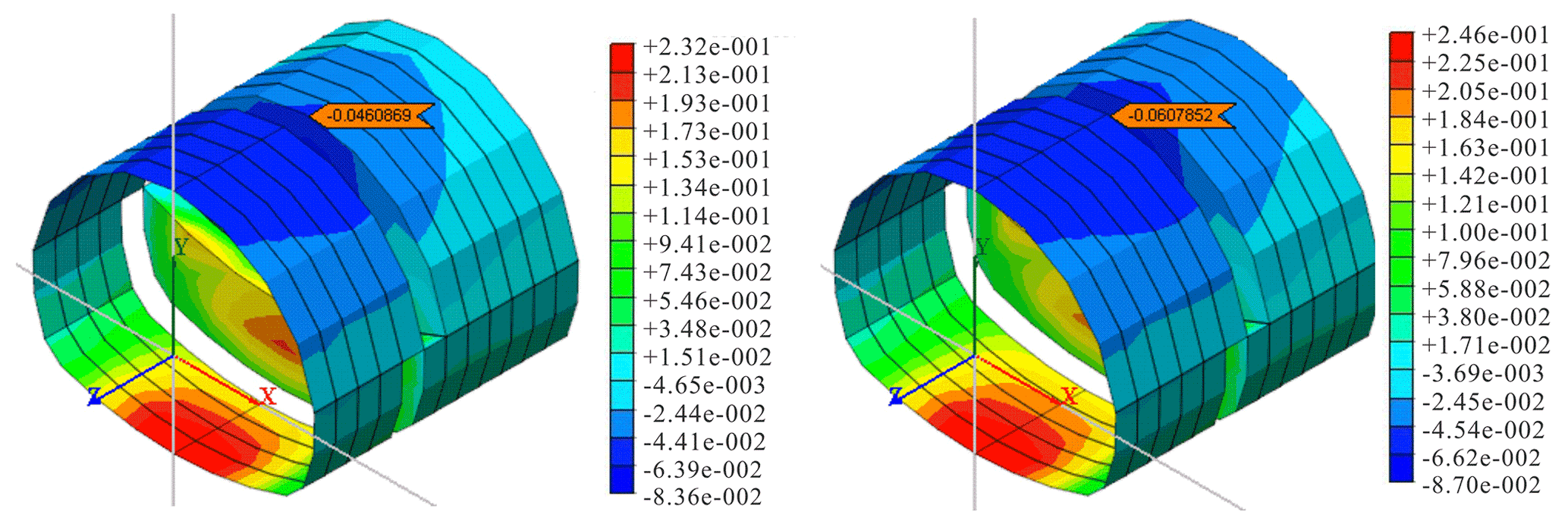
(1) Variation law of the tunnel vault settlement with construction steps. To fully consider the impact of excavation on the completed tunnel, the initial excavation surface of the tunnel is selected as the analysis section. The settlement analysis results of the vault with and without cantilever support are shown in Figs. 11–12.
Figure 13 shows the vault settlement of the excavation section with the increase in the number of construction steps. With the progress of construction, the vertical settlement of the vault in Condition 1 continues to increase. When the tunnel is excavated for 12 m, the vault settlement of the excavation face reaches 71.6 mm. In Condition 2, after the cantilever beam is applied, the vault settlement is controlled, and the maximum settlement is 26.6 mm. When the construction reaches 12 steps, the settlement deformation of the initial section is basically stable.
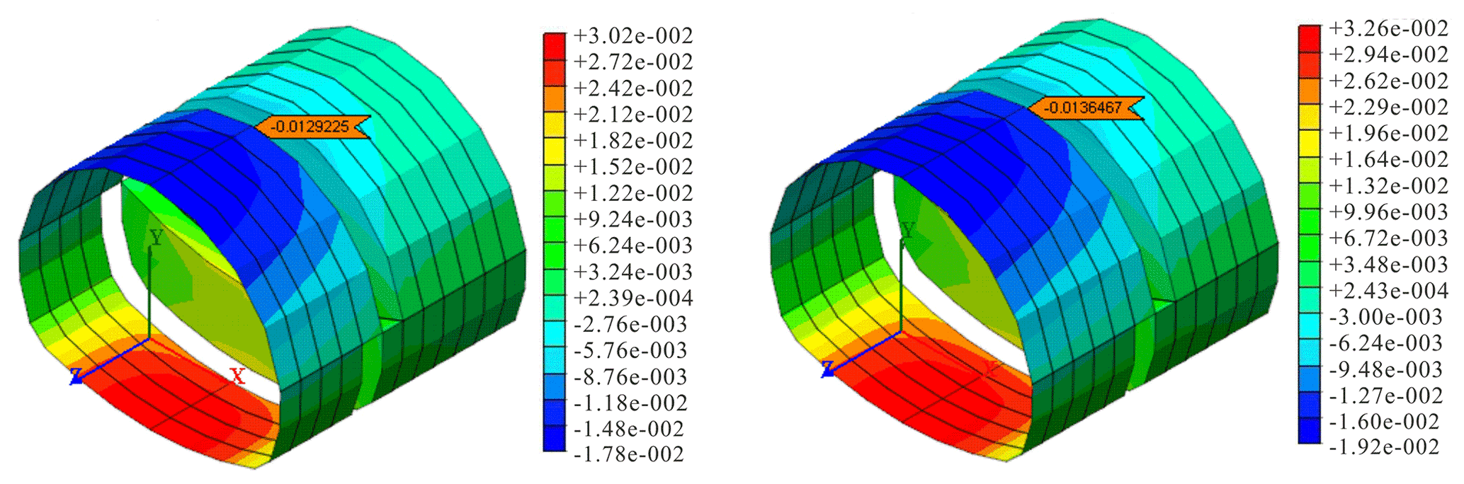
(2) Relationship between the excavation of the upper and lower steps of the tunnel and the settlement of the vault. Excavation section y=6 was selected to analyze the settlement value of the arch crown caused by the excavation of the upper and lower steps of the tunnel. See Figs. 14–15 for the analysis results.
The statistical results are shown in Table 7.
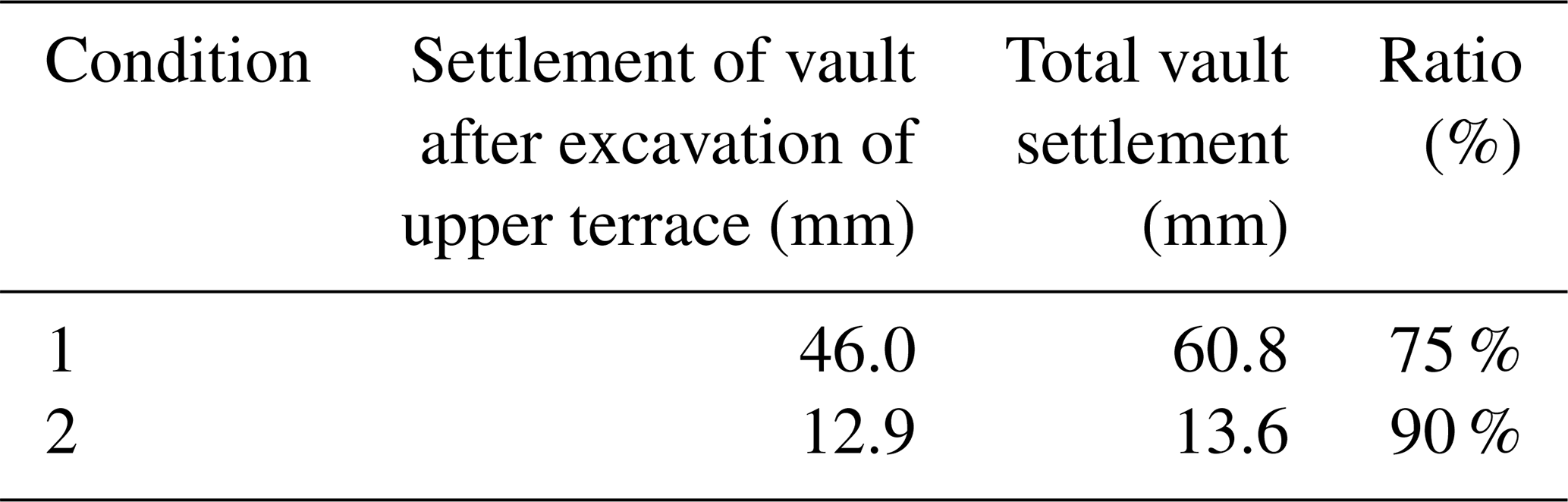
Before the excavation of the lower step, the settlement of the vault caused by the excavation of the upper step is compared, and the settlement of the vault of the model with the cantilever beam accounts for more than 90 % of the total settlement. Thus, the vault settlement is basically stable before the excavation of the lower bench. The cantilever beam can effectively control the deformation around the tunnel caused by the excavation of the upper bench and restrain the deformation of the working face.
3.2 Application effect of the composite cantilever support structure
After 5 m of tunnel excavation, the survey points are set, and the monitoring section spacing is 10 m. After blasting, survey points are arranged, and the initial readings are obtained within 6 h. The surrounding rock convergence of the test section and comparison section is shown in Figs. 16–17, and the convergence monitoring duration is approximately 2 months.
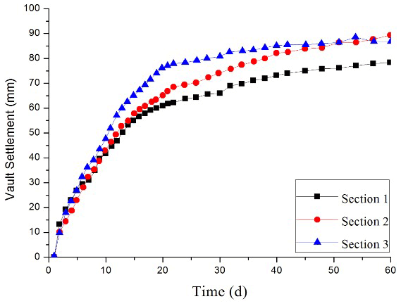
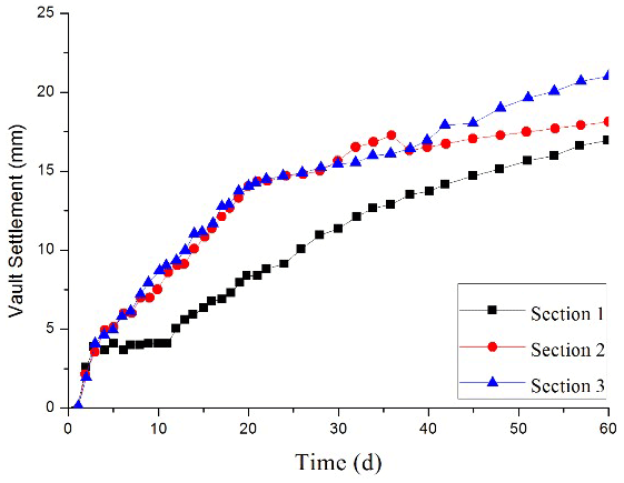
Figure 17Settlement–time curve of the vault supported by the bench method with the composite cantilever support structure.
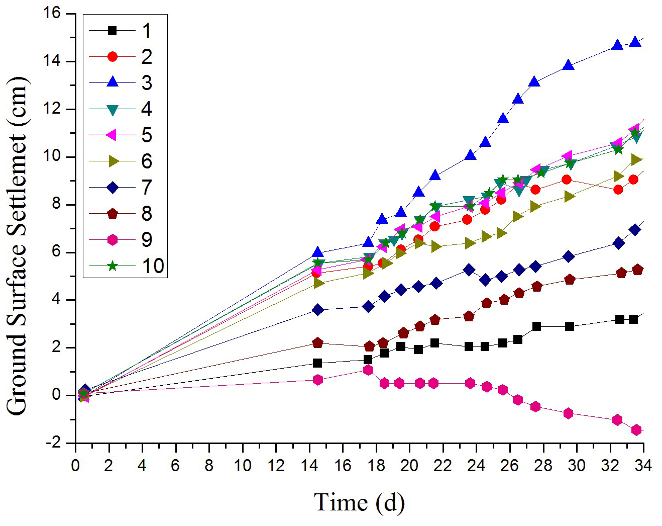
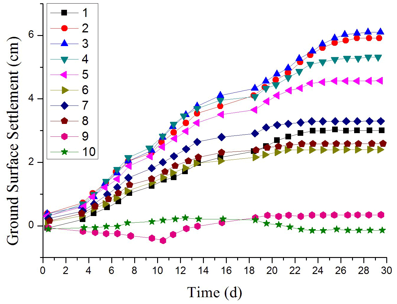
Figure 19Settlement–time curve of the ground surface (bench method with the composite cantilever support structure).
From the monitoring results, the deformation of the surrounding rock in the test section is well controlled by changing the support method and using the composite cantilever support structure. The vault subsidence is 17–22 mm, and the settlement deformation of the vault is obviously reduced. The ground settlement of the test section using the technology of the composite cantilever support structure is also well controlled is shown in Figs. 18–19. The settlement rate of the test section is much less than that of the comparison section. The deformation of the test section tends to be stable for approximately 10 d, while that of the comparison section is more than 20 d.
In this section, we will analyze (1) the calculation and analysis of the initial support structure of the tunnel with the composite cantilever structure and (2) the optimization design of the composite cantilever structure.
4.1 Tunnel calculation and application analysis with a composite cantilever support structure
-
The settlement of the tunnel with a composite cantilever support structure is greatly reduced (the settlement is reduced by more than 60 %). Thus, the auxiliary support structure can effectively control the deformation of the tunnel structure and surrounding rock.
-
In the actual field construction application, whether to adopt the composite cantilever support structure measures depends on the deformation monitoring results of the surrounding rock after the excavation of the upper bench, which cannot be used for the surrounding rock with small deformation.
-
Composite cantilever support structure does not affect other working procedures of the tunnel, and the site operation is convenient.
4.2 Research on the optimal design of the composite cantilever support structure
-
The analysis of the mechanical mechanism of the composite cantilever support structure shows that in the relatively broken surrounding rock, the length of the cantilever beam should be controlled at approximately the tunnel diameter.
-
The angle of the cantilever beam should be controlled at 15∘. The stress of the cantilever beam and the deformation of the supporting structure are reasonable and can further control the settlement deformation of the initial support. The deformation amount is reduced by more than 30 % compared with that of the horizontal driving cantilever beam.
In this paper, we reach the following conclusions: the deformation of the tunnel-surrounding rock can be effectively controlled by adopting the composite cantilever support structure. This method is applied to the soft and broken surrounding rock sections, such as the fault tunnel zone, water-rich section, and shallow buried section of the tunnel portal. It is a very effective construction method for the design of tunnel structures.
The actual measurements and calculations show that the internal force of the supporting structure, the deformation of the tunnel, and the amount of surface settlement are obviously reduced after the composite cantilever support structure is used, and the reinforcement measures are effective for reducing the ground surface subsidence. In the field test, the process flow of the whole composite cantilever support structure is simple and does not affect other construction processes, which has a certain engineering application significance.
Under complex geological conditions, the design parameters of the composite cantilever support structure, such as the embedded depth of the double-wing cantilever beam, must be further studied and verified by engineering.
All the data used in this paper can be obtained from the corresponding author upon request.
JQ and QX designed the study and wrote the manuscript. SB calculated the model and conducted the application research. QX provided guidance on the writing and YL translation of the paper. All the authors gave their final approval for publication.
The contact author has declared that neither they nor their co-authors have any competing interests.
Publisher's note: Copernicus Publications remains neutral with regard to jurisdictional claims in published maps and institutional affiliations.
This work was supported by the National Natural Science Foundation of China (grant no. 42072341) and the Fundamental Research Funds for the Central Universities (grant no. 2-9-2018-096).
This paper was edited by Guimin Chen and reviewed by two anonymous referees.
Brown, E. T., Bray, J. W., Ladanyi, B., and Hoek, E.: Ground response curves for rock tunnels, J. Geotech. Eng.-ASCE, 109, 15–39, 1983.
Guo, Z., Wang, J., Zhang, Y., Pan, Q., and Peng, L.: Failure mechanism and constant resistance large deformation control measures of deep soft rock in qingshui coal mine, Caikuang Yu Anquan Gongcheng Xuebao [Journal of Mining & Safety Engineering], 31, 945–949, https://doi.org/10.1007/0-306-46862-X_151, 2014.
Guo, Z., Li, E., Zhang, Y., Deng, X., and Wang, J.: Study on deformation and failure mechanism of the tectonic stress areas' soft rock roadway in nanshan coal mine, Caikuang yu Anquan Gongcheng Xuebao [Journal of Mining and Safety Engineering], 32, 267–272, https://doi.org/10.13545/j.cnki.jmse.2015.02.015, 2015.
Huang, W. Z., Wang, W. J., and Yu, W. J.: Analysis on secondary support parameter of deep high-stress & broken-expand surrounding rock, Caikuang yu Anquan Gongcheng Xuebao [Journal of Mining and Safety Engineering], 30, 665–672, 2013.
Huo, Y. H.: Study on the gray model and its application in forecasting the deformation of tunnel surrounding rock, Journal of Bjing Jiaotong University, 4, 42–45, https://doi.org/10.3969/j.issn.1673-0291.2006.04.011, 2006.
Kimura, F., Okabayashi, N., and Kawamoto, T.: Tunnelling through squeezing rock in two large fault zones of the enasan tunnel ii, Rock Mech. Rock Eng., 20, 151–166, https://doi.org/10.1007/BF01020366, 1987.
Li, Q. S., Bo, F. L., Ding, X. Y., and Wang, J. S.: Deformation characteristics of soft rock roadway in deep mines and supporting control technology, Journal of Shan-dong University of Science and Technology (Natural Science), 29, 8–14, https://doi.org/10.16452/j.cnki.sdkjzk.2010.04.006, 2010.
Li, X., Yao, Q., Man, J., Chen, C., and He, L.: Development of fractures in soft rock surrounding a roadway and their control, Mining Science & Technology, 21, 573–579, https://doi.org/10.1016/j.mstc.2011.02.026, 2011.
Li, Y. and Xu, C. B. S.: Analysis of Long term Deformation of Tunnel Surrounding Rock of Dyoushan Tunnel, Journal of Highway and Transportation Research and Development, 30, 120–124, 2013.
Lin, L. Q., Sheng, H. Z., Dong, H. X., Li, D. W., and Bin, X. Q.: Monitoring and analysis on the deformation of tunnel surrounding rock affected by faults, Hydrogeology and Engineering Geology, 32, 102–107, https://doi.org/10.1007/s11769-005-0030-x, 2005.
Liu, Y., Wu, X, J., Liu, Z. Q., Liu, Y. Y., and Su, B.: Discussion of and solutions for the large deformation mechanism of a tunnel in carbonaceous slate, Modern Tunnelling Technology, 51, 19–24, https://doi.org/10.13807/j.cnki.mtt.2014.06.004, 2014.
Niu, J. C., Gao, J. P., Zhang, S. J., Ding, Y. H., and Zhu, S. Y.: Comprehensive analysis on surrounding rock stability of deep soft rock roadway and supporting practice, Mining Safety & Environmental Protection, 42, 68–71, 2015.
Oreste, P. P.: Analysis of structural interaction in tunnels using the convergence-confinemen approach, Tunn. Undergr. Sp. Tech., 13, 347–363, https://doi.org/10.1016/S0886-7798(03)00004-X, 2003.
Panet, M. and Guenot, A.: Analysis of convergence behind the face of a tunnel: Tunnelling 82, proceedings of the 3rd international symposium, Brighton, 7–11 June 1982, P197–204, IMM, London, 1982, Int. J. Rock Mech. Min., 20, A16, https://doi.org/10.1016/0148-9062(83)91744-8, 1983.
Qing, L. S., Jun, W. W., Liang, P. C., and Lei, Y.: Numerical analysis on influence of reinforcing floor on stability of sides in deep soft rock roadways, Journal of China Coal Society, 28, 210–216, https://doi.org/10.1016/S1872-2067(07)60020-5, 2007.
Sun, L., Wu, H., Yang, B., and Li, Q.: Support failure of a high-stress soft-rock roadway in deep coal mine and the equalized yielding support technology: a case study, International Journal of Coal Science & Technology, 002, 279–286, 2015.
Varljen, J., Baticic, L., Sincicmodric, G., Varljen, N., and Kapovic, M.: Long term measurements in underground openings and their interpretation with special consideration to the rheological behaviour of the rock, Int. J. Rock Mech. Min., 16, 286–298, https://doi.org/10.1016/0148-9062(79)90600-4, 1977.
Wang, W. F.: Key points and large deformation control in construction of tunnel in carbonaceous slate, Tunnel Construction, 30, 697–700, 2010.
Weidinger, F. and Lauffer, H.: The tauern tunnel first and second tubes from the contractor's viewpoint. tauerntunnel erste und zweite Röhre aus der Sicht des Bauausführenden, Geomechanics & Tunnelling, 2, 24–32, https://doi.org/10.1002/geot.200900002, 2009.
Wu, A., Chen, S., Wang, Y., and Chen, X.: Failure mechanism and supporting measures for large deformation of soft rock roadway in baluba copper mine, Arch. Min. Sci., 63, 449–464, https://doi.org/10.24425/122458, 2018.
Wu, F., Miao, J., Bao, H., and Wu, J.: Large Deformation of Tunnel in Slate-Schistose Rock, in: Lollino, G., Giordan, D., Thuro, K., Carranza-Torres, C., Wu, F., Marinos, P., and Delgado, C., Engineering Geology for Society and Territory – Volume 6, Springer International Publishing, https://doi.org/10.1007/978-3-319-09060-3_3, 2015.
Wu, J. G. and Zhu, H. Y.: Discussion of the rock classifification and selection of support parameters for a soft rock tunnel with large deformation, Modern Tunnelling Technology, 49, 10–16, https://doi.org/10.13807/j.cnki.mtt.2012.04.003, 2012.
Xue, Q., Leung, H., Huang, L., Zhang, R., Liu, B., Wang, J., and Li, L.: Modeling of torsional oscillation of drillstring dynamics, Nonlinear Dynam., 96, 267–283, https://doi.org/10.1007/s11071-019-04789-x, 2019.
Yang, J., Yu, S., Tao, Z., Sun, X., and Wang, D.: On the deformation and failure characteristics of the tertiary soft rock roadway and coupling control measures, Caikuang yu Anquan Gongcheng Xuebao [Journal of Mining and Safety Engineering], 31, 373–378+384, 2014.
Yang, X., Lou, H., Nan, C., Dong, G., Xiao, L., and Jiao, Y.: Study on large deformation mechanism and support of soft rock road way, Coal Sci. Technol., 43, 1–6, https://doi.org/10.13199/j.cnki.cst.2015.09.001, 2015.
Zheng, P. Q., Cheng, W. Z., Tan, X. J., and Dai, Y. H.: Study of failure mechanism of floor heave and supporting technology in soft rock of large deformation roadway, Chinese Journal of Rock Mechanics and Engineering, 34, 3143–3150, https://doi.org/10.13722/j.cnki.jrme.2014.0185, 2015.