the Creative Commons Attribution 4.0 License.
the Creative Commons Attribution 4.0 License.
 | 21 Oct 2022
Evolution and mechanism configuration synthesis of chamber clocks movement prior to 1700
Tsung-Yi Lin
Wen-Feng Lin
Chamber clocks are weight-driven wall clocks and the first type of domestic clocks to be widely used in the home. During the 16th and 17th centuries, although horologists in Europe made various types of chamber clocks in large numbers, many of the clocks have since been either replaced or discarded. In this study, we used the method of mechanical evolution and variation, analyzed and compared clock movements based on historical data and existing clocks, and synthesized all possible movement configurations of early-day chamber clocks. A total of 4 going-train configurations and 10 striking-train configurations were identified, making a total of 40 feasible movement configurations. In addition, 14 existing representative chamber clocks were selected as examples to illustrate the above configurations and their variations, which enabled the creation of a comprehensive atlas of the movement designs. The results of the study can not only help to systematically carry out the reconstruction design of various chamber clocks, but also provide new information for scholars of history of science to further historical research and develop new materials for creativity as well as science and technology education.
- Article
(14224 KB) - Full-text XML
- BibTeX
- EndNote


In recent years, we have conducted reconstruction research on ancient machinery. We were able to not only determine the likely original forms of these pieces of machinery, but also systematically piece together the technical context and knowledge system involved. We were thus able to attract young students and achieve tangible results by furthering innovation and develop new materials for creativity, science and technology education. This paper focuses on the reconstruction study of chamber clocks before the year 1700, and it is hoped that the results will be of help to future pedagogy and reconstruction efforts.
Chamber clocks are a type of weight-driven wall clocks and the first type of domestic clocks to be widely used in the home. A typical chamber clock had an end-to-end birdcage frame, a dial, a single hour hand, and a bowl-shaped large bell above the frame. The shape and stylistic features of the frames, as well as the painting and patterns of the dials, exhibited cultural characteristics unique to horologists from different parts of the world. The main types of chamber clocks include the European Gothic clock and English lantern clock, as shown in Fig. 1.
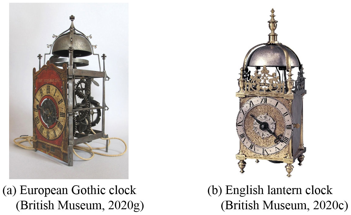
Figure 1Chamber clocks.
Most likely originating before 1500, European Gothic clocks were primarily made of iron and were made by horologists in Europe, especially in Germany, France and Switzerland. Most well-known are the chamber clocks made by the Liechti family. A study of the clock's development showed that European Gothic clocks evolved from tower clocks, and that its movement was actually a miniaturized version of the tower clock movement (Robey, 2018).
On the other hand, English lantern clocks were developed during the late 16th century and made of brass and iron. Most of the clocks were made in England rather than in Germany. After 1600, they became popular and was the main type of chamber clocks in use in England and Europe. The English lantern clock was different from the European Gothic clock in that its frame was made up of four corner pillars affixed to a square base and top plates with screws, and a series of vertical plates arranged in parallel to install the movement. The dial had a large circular numeral ring, and an engraved cast-brass fret sat above the dial. These styles gradually evolved into the standards of the English horology guild, leading to the standardization of components and the creation of a production supply chain. Thus, there was little change in the physical form of the English lantern clocks during the course of its development. The standard height of a lantern clock was approximately 38 or 41 cm (Robey, 2016; Robey and Gillibrand, 2013).
In the 1670s, the verge escapement was replaced by the anchor escapement. This required a longer pendulum and therefore a longer case, resulting in the European Gothic clocks and English lantern clocks being replaced by longcase clocks (National Trust for Scotland, 2020).
This study focuses on European chamber clocks made before 1700 and traces their mechanical evolutions to explore and analyze the mechanisms and technologies of the movements (Liang and Liang, 2000; Liang and Shu, 2006; Lin, 2020; Teng et al., 2004; Yan, 2009), identify design patterns, generalize and classify the patterns, and finally, synthesize the different movement configurations in a systematic manner. The results of this study can help provide new information for scholars of history of science to determine the original designs and structures of chamber clocks, which could be used to further innovation and develop new materials for creativity as well as science and technology education.
Although horologists in Europe made various types of chamber clocks in large numbers during the 16th and 17th centuries, many of the clocks were replaced and discarded, especially those made before 1657. To improve timekeeping accuracy, foliots and balance wheels were replaced by pendulums around 1659–1660. After the invention of the anchor escapement in 1670, pendulum and verge-escapement regulators were replaced by pendulum and anchor-escapement regulators. Despite these improvements, little changes were made to the striking train.
Due to time and budget constraints, it was difficult to obtain access to the original chamber clocks and other relevant data. In addition to the available historical data from books and journals, the current study also used search engines to collect data on chamber clocks from the Internet. Many chamber clocks have since become collector items after the 19th century, and have undergone varying degrees of repair and restoration. Many of the existing chamber clocks are also either replicas or imitations. These, however, did not adversely affect the current study, but instead provided additional information that benefited the current reconstruction study. In addition, chamber clocks were a mass-produced product, and the clocks made by various manufacturers were more standardized than tower clocks. In particular, the production of the English lantern clocks during the 17th century benefitted from an effective guild system, which standardized components and divided work in the production process (Wikipedia, 2019).
Table 1Mechanisms and configurations of the 14 existing representative chamber clocks. (The indicated year of production does not represent the year the configuration was developed. The order in which the clocks are presented also does not indicate the evolutionary order.)
The scope of this study was limited to weight-driven chamber clocks produced before the 17th century, particularly the European Gothic clocks and English lantern clocks. Using historical data and existing clocks, the study compared and analyzed the movement mechanisms, and the results are listed in Table 1, which lists 14 representative chamber clocks that are currently in existence.
In this study, N2 in Table 1 was first used as an example to analyze its movement mechanism and synthesize all possible movement configurations. The movements of the 14 representative chamber clocks listed in Table 1 were then analyzed to construct a comprehensive atlas of the movement designs.
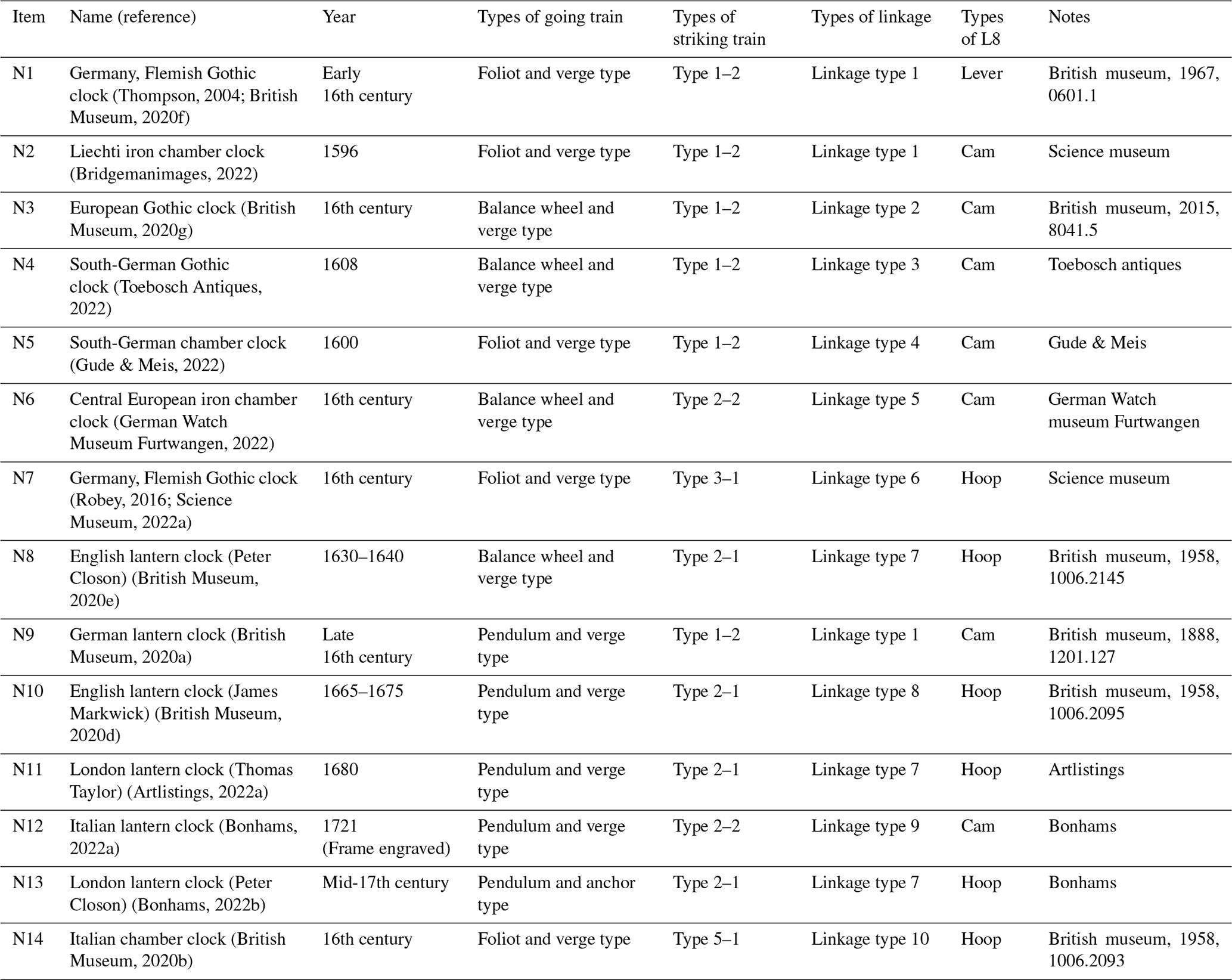
The core of a chamber clock is the movement, which is primarily composed of a going train and a striking train. Movements were initially hour-striking, and later iterations included an alarm and quarter-striking function. This paper will focus on movements with hour-striking function, and will use chamber clock N2 as shown in Fig. 2 to explain the movement mechanism and design.
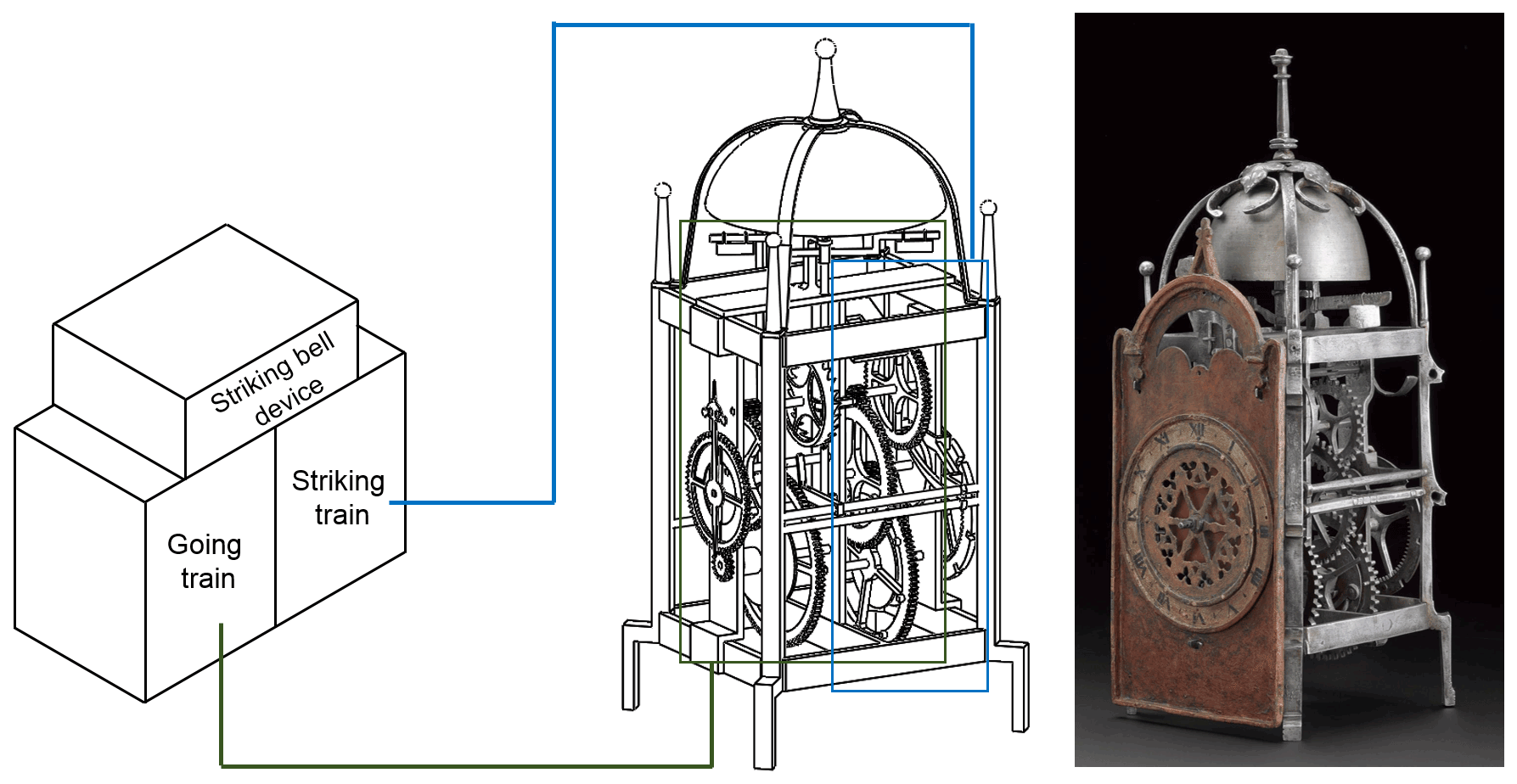
Figure 2N2 – Liechti iron chamber clock (Science Museum, 2022b).
3.1 Historical research
According to historical records, the Liechti iron chamber clock, shown in Fig. 2, was built in 1596 and was one of the chamber clocks made by the Liechti family of Winterthur, Switzerland. Erhard Liechti (∼ 1530–1591), who first made these chamber clocks, affixed his initials “EL” to all his works. His two sons, Ulrich Liechti (1560–1627) and Andreas Liechti (1562–1621), inherited his clock-making business and also affixed their initials “UAL” onto their clocks (Bridgemanimages, 2022). Unlike the typical European Gothic clocks, which were un-initialed, it was more common for English lantern clocks to be initialed (Robey, 2016, 2012).
The movement of the Liechti iron chamber clock was arranged end-to-end inside a birdcage, i.e., the going train and the striking train were arranged end-to-end and housed inside a rectangular birdcage. The operations of the movement are explained in the following sections.

3.2 Analysis of the going-system mechanism
The going system, as shown in Fig. 3, is used to keep time and includes a power-transfer mechanism, a going train, and an escapement regulator. A trigger lever (L1) outputs a signal to activate the striking.
-
Power-transfer mechanism: It consists of a capstan (rope pulley, rope, weight) and a capstan ratchet device (ratchet and pawl). The power-transfer mechanism uses the torque generated by the weight on the rope pulley to provide power to the going system.
-
Going train: It consists of three sets of gears, namely, the great wheel (G6) and pinion (G5), the second wheel (G4) and second pinion (G3), and the hour-hand pinion (G7) and hour-hand wheel (G8). The gear train is so designed that the hour-hand wheel (G8) completes one revolution every 12 h ( rph = rpm).
-
Escapement regulator: It is composed of the foliot and verge escapement (verge and crown wheel). The period of oscillation of the foliot is a timing unit (3.94 s).
Because the output of the going train is the hour-hand wheel, the rotation speed of which is ωG8 = rpm = rps, the frequency of oscillation of the foliot is ωG1, and its period of oscillation is . Therefore, the velocity ratio (γ) of the going system is as shown in Eq. (1), where TG1 represents one oscillation of the foliot, TG2 is the number of teeth of the crown wheel (19 teeth), TG3 is the number of teeth of the second pinion (6 teeth), TG4 is the number of teeth of the second wheel (48 teeth), TG5 is the number of teeth of the pinion (8 teeth), TG6 is the number of teeth of the great wheel (48 teeth), TG7 is the number of teeth of the hour-hand pinion (6 teeth), and TG8 is the number of teeth of the hour-hand wheel (72 teeth). Using Eq. (1), the period of oscillation of the foliot is calculated to be 3.94 s:
3.3 Analysis of the striking system mechanism
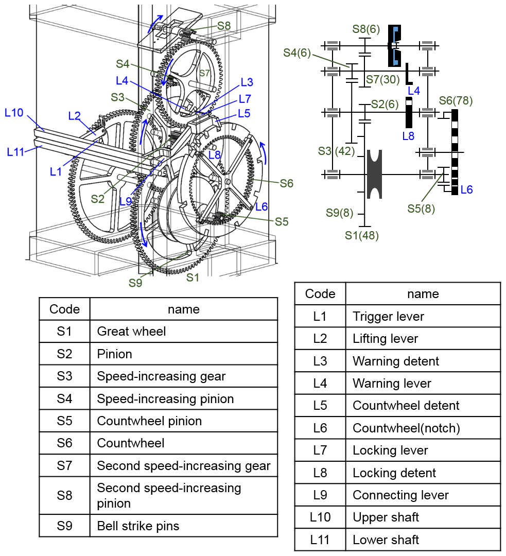
The striking system, as shown in Fig. 4, is composed of a power-transfer mechanism, a striking train, a speed-reduction mechanism, and a trigger mechanism that is used to control the number of strikes.
-
Power-transfer mechanism: The structure is the same as that of the going system and is also driven by a weight.
-
Striking train: It consists of four sets of gears, namely, the great wheel (S1) and pinion (S2), speed-increasing gear (S3) and speed-increasing pinion (S4), count-wheel pinion (S5) and count wheel (S6), and second speed-increasing gear (S7) and second speed-increasing pinion (S8). The velocity ratio is designed such that for each revolution of pinion (S2), the count wheel (S6) moves by one tooth; therefore, the number of teeth of the great wheel (TS1) is an integer multiple (N) of the pinion (TS2). When the number of teeth of the count wheel (TS6) is 78, then the number of teeth of the count-wheel pinion (TS5) will be N. At the same time, there are also N number of bell strike pins (used to trigger the hammers) on the great wheel. When the number of teeth of the count wheel is a multiple (α) of 78, the number of teeth of the count-wheel pinion will be a multiple (α) of N, as shown in Eq. (2).
-
Speed-reducing mechanism: It is composed of two pairs of speed-increasing gears (the speed-increasing gear and speed-increasing pinion, plus the second speed-increasing gear and second speed-increasing pinion) and a fly (a pair of blades and a one-way ratchet mechanism). The velocity ratio is independent of the striking train. Generally, the velocity ratio is between 50–100, the main purpose of which is to reduce the falling speed of the weight to prevent the weight from falling faster and faster, so as to maintain constant motion of the striking train and reduce the impact of its stopping action.
-
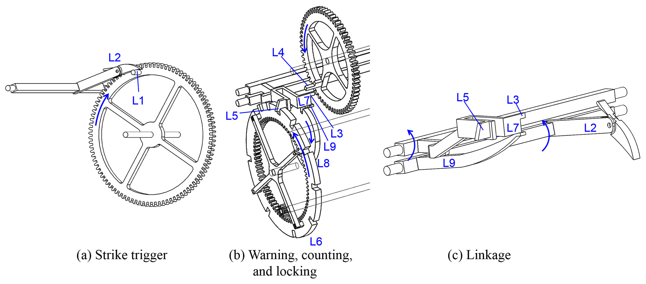
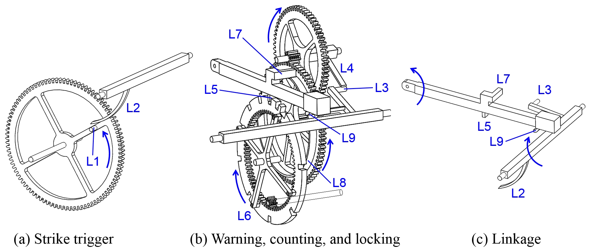
Trigger mechanism: It is composed of the trigger lever (L1), lifting lever (L2), warning detent (L3), warning lever (L4), count-wheel detent (L5), count wheel notch (L6), locking lever (L7), locking detent (L8), and connecting lever (L9). When the time approaches the hour, the trigger lever (L1) will raise the lifting lever (L2), and the striking train then enters into the warning mode (standby), waiting to strike on the hour. The structure and function of the trigger mechanism are explained below.
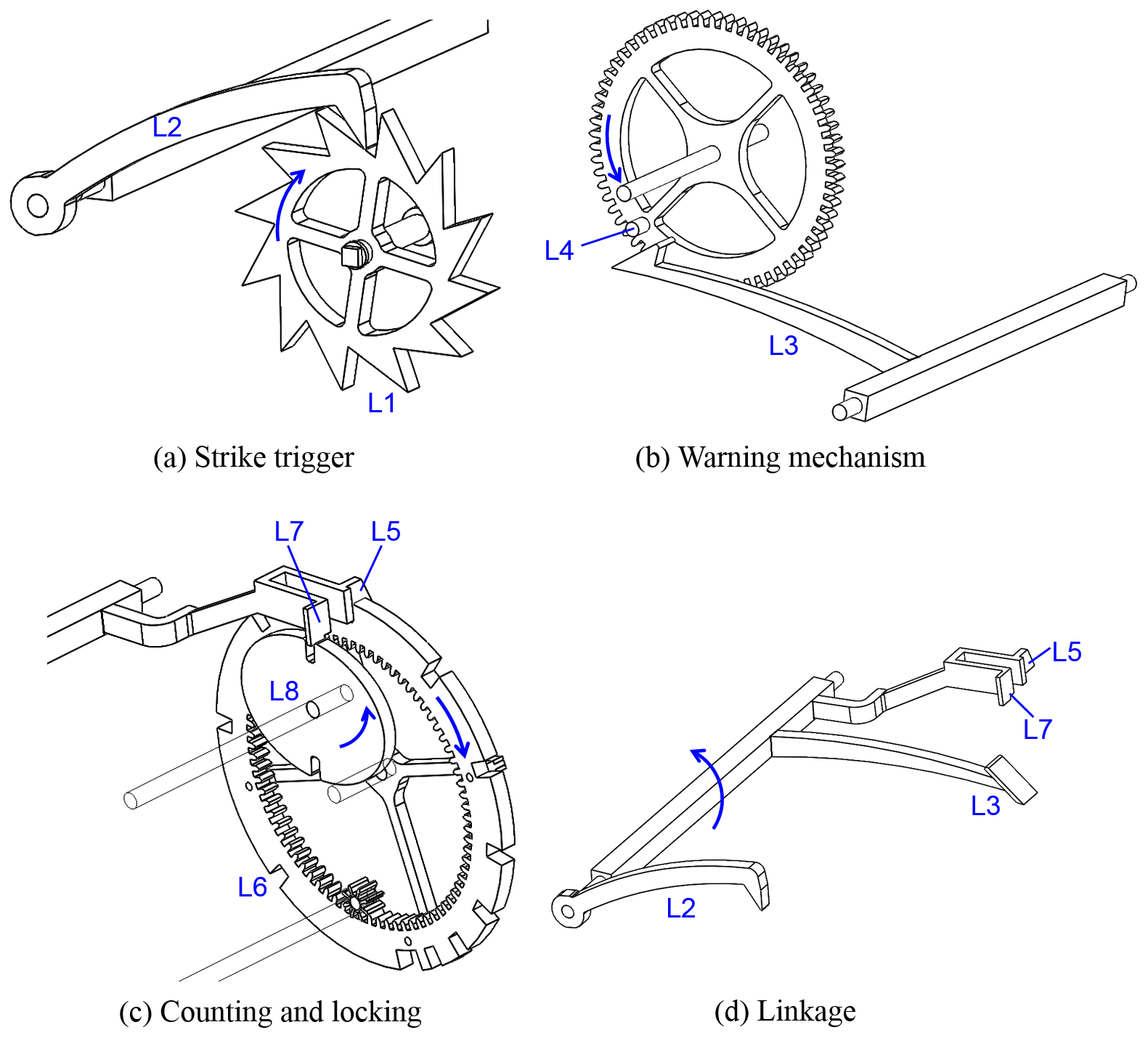
The trigger mechanism of the Liechti iron chamber clock (N2) consists of four pairs of inter-connected levers, namely, L1 and L2, L3 and L4, L5 and L6, and L7 and L8, as shown in Fig. 4. Each lever pair performs the following functions, respectively: trigger, warning, counting (for use as a control), and locking. Levers L3, L5, and L7 are mounted on the same lever.
-
Trigger: L1 is the trigger lever, which is a pin near the outer rim of the great wheel of the going train; L2 is the lifting lever, which is affixed to the lower shaft (L11). A “nag's head” is attached to the end of L2 to adjust the accuracy of time-keeping, and is replaceable when it becomes worn due to friction. Lever L9 is the connecting lever, which is also affixed to the lower shaft. Moving clockwise along with the great wheel (G4), L1 lifts L2 when approaching an hour. This action also lifts L9, which in turn lifts L5 from the notch on L6, thus releasing the entire striking train.
-
Warning function: L3 is the warning detent, which is affixed to the upper shaft (L10). The detent works in conjunction with the warning lever (L4), which is a pin on the second speed-increasing gear. When the striking train is released, L4 will rotate counter-clockwise along the second speed-increasing gear. After moving by a small angular distance, it will be blocked by the detent at L3, thus stopping the movement of the striking train.
-
Counting: L5 is the count-wheel detent, which works in conjunction with the count-wheel notches (L6). It is used to count and control the number of strikes. Typically, L5 is on the same lever as L7 and they move in unison.
-
Locking: L8 is the locking detent, which is positioned on the cam on the same arbor as the speed-increasing gear; there is a notch on the cam. Lever L7 is the locking lever, and its detent works in conjunction with the notch on L8. When L1 continues to move clockwise, L3 (same with L5 and L7) will move to a specific height together with L2 on the hour, releasing L4, L6 and L8. At this moment, the entire striking train will be released due to the torque produced by the weight. The striking train starts to rotate freely, thus activating the striking system. At the same time, L1 slides over L2, L2 is lowered together with L9, thus L5 (same with L7 and L3) is also lowered until the L5 detent drops and slides along on the rim of the count wheel. During this time, for every L8 turn, the striking pin on the great wheel (S1) will move the strike lever, which will pull on the rope to make a strike.
At the end of a strike, the count-wheel detent (L5) falls into the count-wheel notch (L6), while the locking lever (L7) falls into the notch of the cam (L8). The striking train then comes to a stop, while the fly continues its movement to release energy until it comes to a full stop. This completes a striking cycle.
By analyzing and comparing historical data of early-day chamber clocks and existing clocks, the following possible configurations of going trains and striking trains were identified. They are explained in the following sections.
4.1 Configurations of the going-system mechanism
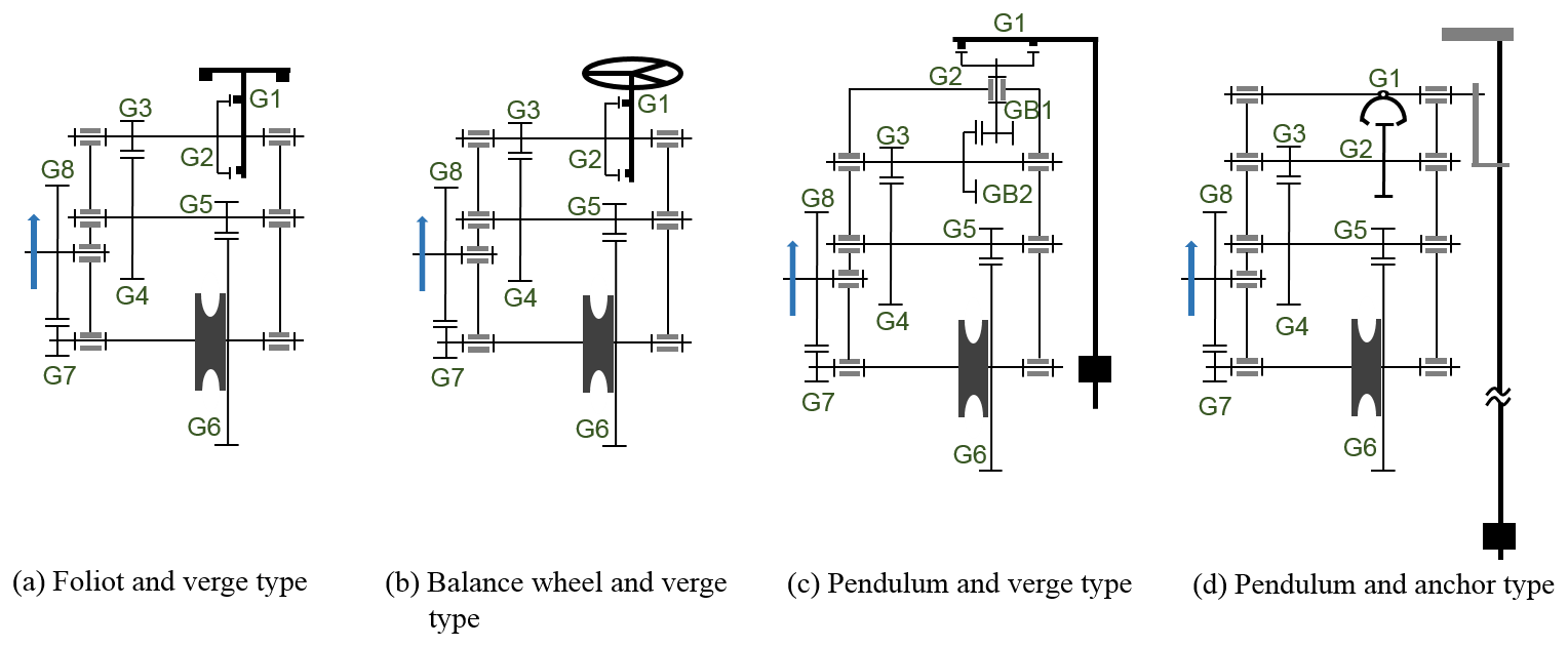
The configurations of going systems in chamber clocks are classified by the type of escapement regulator used, which in turn determines the configuration of the clock's going train. Before 1700, four types of escapement regulators were in use: foliot and verge-escapement regulator, balance wheel and verge-escapement regulator, pendulum and verge-escapement regulator, and pendulum and anchor-escapement regulator. This resulted in four different going-system configurations, as shown in Fig. 5.
4.1.1 Foliot and verge type
Believed to be the earliest type of movement configuration, the foliot and verge type was the main type in use before 1657. This configuration used a foliot and verge-escapement regulator, with a structure similar to that of a tower clock, as shown in Fig. 3. The foliot balance was a type of oscillator, where its oscillation frequency was one unit of time. The balance included two movable weights hanging from the foliot used to adjusting its oscillation frequency; the heavier the weight or the farther away it was from the axis, the lower the oscillation frequency. On the other hand, the verge escapement is a recoil escapement that consisted of a vertical rod (verge) with two metal plates (pallets), which were oriented with an angle in between them and were attached near the opposite ends of the rod. As the foliot oscillated, only one pallet would catch a tooth of the crown wheel at a time, thus producing an intermittent motion. The foliot and verge-escapement regulator had an error of approximately plus or minus 15 min d−1 (Andrewes, 2002).
4.1.2 Balance wheel and verge type
There is no evidence that shows that the first chamber clock did not use a balance wheel and verge-escapement regulator, since both the balance wheel and verge configuration and the foliot and verge configuration were typical going-system configurations prior to 1657. In particular, almost all lantern clocks during 1600–1660 used balance wheels and verge-escapement regulators. For the Gothic clocks listed in Table 1, the operations of the balance wheels and foliots, as well as their assembly, were similar. The diameter of the balance wheel was similar to the length of the horizontal rod (such as the foliot), and the center of the rod was affixed to an arbor and suspended inside the frame (Robey, 2018), as shown in N3 Fig. 11. On the other hand, the balance wheels in lantern clocks were affixed to an arbor using a horizontal rod about half the wheel's diameter in length, which in turn was directly affixed to the frame, rather than being suspended, as shown in N8 in Fig. 22. The oscillation speed of the balance wheel was adjusted by increasing or decreasing the weight of the balance wheel, and the error was about plus or minus 15 min d−1 (Andrewes, 2002).
4.1.3 Pendulum and verge type (made between 1660–1680)
After Christiaan Huygens invented the pendulum clock in 1657, pendulums and verge-escapement regulators were soon used in lantern clocks in 1658. The verge and crown wheel were positioned horizontally, and a set of vertical gears (the third wheel and third pinion) was added to the going train, as in N9 in Fig. 24. Initially, short pendulums were used. For lantern clocks, the length was shorter than the distance between the top and bottom plates, which was about 6 in. For this reason, the pendulums were also referred to as short pendulums, bob pendulums, or verge pendulums. The pendulums were typically installed at the rear, either inside or outside the frame. Others, called center-verge pendulums, were installed at the center of the frame, between the going and striking trains, as shown in N11 in Fig. 29. The timekeeping error was about 1–2 min d−1. To further improve accuracy, short-pendulum lantern clocks were replaced by long pendulums, just as the balance wheel and verge type had been replaced by pendulum and verge type (Brian Loomes, 2022).
4.1.4 Pendulum and anchor type (made after 1680)
The anchor escapement used in tower clocks around 1670 was designed to reduce pendulum swing to improve isochronism. Around 1680, lantern clocks started to use pendulums and anchor-escapement regulators. The pendulum was a long pendulum about 91.44 cm in length, which was 6 times longer than a short pendulum (Brian Loomes, 2022). The timing error was approximately 1 min or less per day.
However, the long pendulums used in lantern clocks were exposed. To encase the pendulum, elongated wooden boxes were used, which eventually led to the development of longcase clocks. After 1680, lantern clocks were eventually replaced by longcase clocks.
4.2 Configurations of the striking-system mechanism
The striking-system configuration is primarily dependent on the gear arrangements of the striking train and the type of trigger mechanism.
4.2.1 Types of striking train
Arrangement of the gears and pinions in the striking train is dependent on the relative placements of the great wheel, count wheel, and speed-increasing gear to the rope pulley. Because the great wheel is always on the inner side (placed towards the movement's center), there are five different types of striking-train configurations:
-
Type 1: The count wheel is positioned at the movement's outer side (away from the movement's center), and both the speed-increasing gear and great wheel are at the inner side (towards the movement's center).
-
Type 2: The count wheel is positioned at outer side of the movement, and the speed-increasing gear is also at the outer side.
-
Type 3: The count wheel and great wheel are positioned at the inner side, and both the speed-increasing gear and great wheel are also at the inner side.
-
Type 4: The count wheel and great wheel are positioned at the inner side, and the speed-increasing gear is at the outer side.
-
Type 5: The count wheel and great wheel are perpendicular to each other.
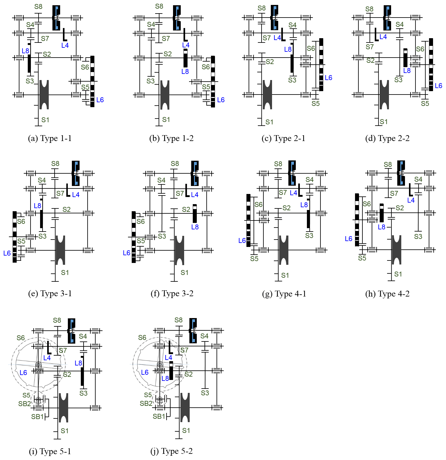
4.2.2 Types of trigger mechanism
The development of the trigger mechanisms is very diverse. Some chamber clocks did not have a warning detent (L3) and warning lever (L4), while others required a connecting lever (L9). Either way, most trigger mechanisms consisted of not more than nine levers. Among them, L1, a lever attached to the great wheel or hour-hand wheel shaft in the going train, triggers the strike mechanism. The L6 are notches on the count wheel, L4 is positioned on the speed-increasing pinion shaft, while L8 is positioned on the cam on the same arbor as the speed-increasing gear. The other elements, i.e., L2, L3, L5, L7, and L9 form the linkage assembly.
To avoid too many and too detailed classifications of the striking-system configuration, this study only takes into account the most important consideration in the design of a trigger mechanism: the position of the locking detent, i.e., whether L8 is positioned on the speed-increasing gear. In this study, the striking-system configurations are classified based on (1) the five types of gear arrangements of the striking trains and (2) the two positions of the locking detent. A total of 10 configurations (5 ⋅ 2 = 10) were identified, as shown in Fig. 6.
The above classification did not take into account the type of linkage. The reasons are as follows: (1) The type of linkage used is primarily determined by the configuration of the above striking systems. After each striking-system configuration is identified, a corresponding type of linkage will also be determined; the number of matches as a result will be limited. Thus any difference will only be regarded as a variant. (2) In addition, the forms of the levers (L1–L9) differ widely. Different forms of levers are also regarded as variants.
The following sections contain structural analyses of the 14 existing representative chamber clocks listed in Table 1. The analyses could be used not only as design examples for the different configurations, but also to create a design atlas for the reconstruction of early-day chamber clocks.
N1 – Germany, Flemish Gothic clock
Clock N1 is a Flemish Gothic clock manufactured around 1520. Its going system uses a foliot and verge type, as shown in Fig. 7. The striking-system configuration is Type 1–2. It is similar to the Liechti iron chamber clock N2 shown in Fig. 4, the simplified diagram of which is shown in Fig. 6b. The N1 trigger mechanism is shown in Fig. 8. Lever L4 is a crank positioned on the speed-increasing pinion shaft. The count-wheel is an internal gear with its teeth cut in the internal surface of the gear body, and the notches are distributed along its outer rim. For this reason, the count wheel moves in the same direction as the rope pulley. Lever L8 is not positioned on the speed-increasing gear, and together with the count wheel, is positioned at the movement's outer side (away from the movement's center); L8 is a crank that moves in opposite direction to the rope pulley.

Figure 7N1: German iron chamber clock (British Museum, 2020f).

Lever L1, a pin positioned on the great wheel, is used to raise L2 and cause movement to L9, as shown in Fig. 8a. Figure 8b shows the mechanism of and interaction between L3 and L4, L5 and L6, and L7 and L8. Figure 8c illustrates the strike linkage, where L3, L5, and L7 are positioned on the same lever, while L2 and L5 (same as L3 and L7) are positioned on different levers and on different sides. Both L2 and L9 are on the same lever and move in unison, and L9 lifts L3 (L5 and L7). The linkage thus consists of two levers. This linkage, which is the same as that in the Liechti iron chamber clock (N2), is a variant of Linkage Type 1.
N2 – Liechti iron chamber clock
Clock N2 is a Liechti iron chamber clock. Its going system uses a foliot and verge type, and its striking-system configuration is Type 1–2. The trigger is shown in Fig. 9, where L4 is a pin-wheel attached to the second speed-increasing gear. The count wheel is an internal gear. Lever L8 is a cam with a notch at the outer rim. It is not positioned on the speed-increasing gear, and together with the count wheel, is positioned at the movement's outer side (away from the movement's center). Figure 9c illustrates the N2 striking linkage, which is Linkage Type 1, a common linkage used with Type 1–2 striking-system configuration. While L3, L5 and L7 are positioned on the same lever, L2 and L5 (along with L3 and L7) are on different levers but positioned on the same side. Both L2 and L9 are on the same axis and thus move in unison; L9 lifts L5 (L7 and L3). The linkage thus consists of two levers.
N3 – European iron Gothic clock
Clock N3 is a European iron Gothic clock manufactured in the 16th century. Its going system uses a balance wheel and verge type, as shown in Figs. 10 and 11. The striking-system configuration is Type 1–2, which is similar to N2. The N3 trigger mechanism, shown in Fig. 12, is also similar in structure to N2 despite some differences in the arrangement of the linkage. Levers L2 and L5, as well as L3 and L7, are on the same axis and move in unison. (There is no L9.) The linkage thus consists of only one lever, as shown in Fig. 9b. This is Linkage Type 2, which was also commonly used in a Type 1–2 striking-system configuration.
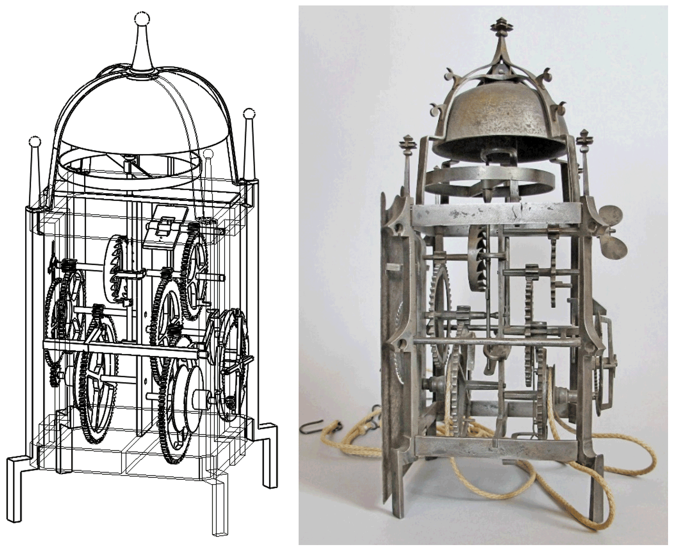
Figure 10N3 – European iron Gothic clock (British Museum, 2020g).
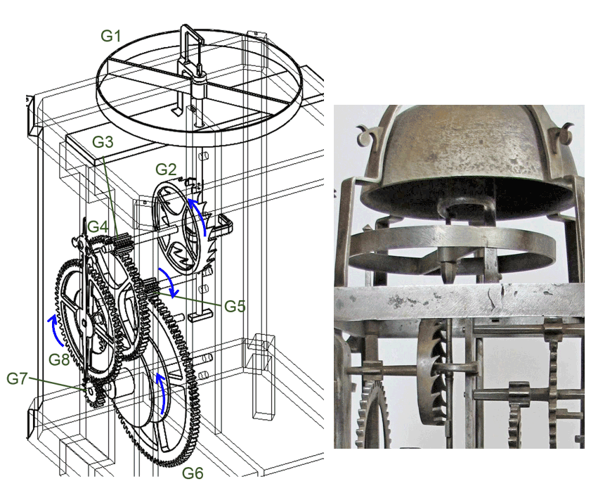
Figure 11Structure and operation of the N3 going system (British Museum, 2020g).
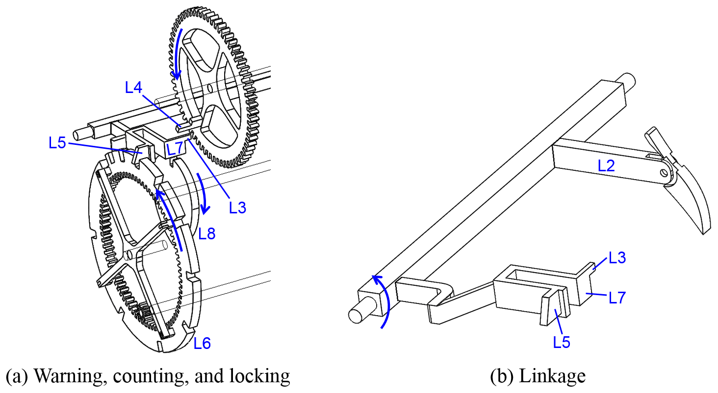
Figure 12Mechanism and operation of the N3 trigger mechanism. (The trigger is similar to that of N2.)
N4 – South-German Gothic clock
Clock N4 is a South-German iron Gothic clock manufactured in 1608. Its going system uses a balance wheel and verge type similar to that of N3, as shown in Fig. 13. The striking-system configuration is Type 1–2, and its mechanism is the same as that of N2. The trigger mechanism, shown in Fig. 14, is similar to that of N2, except for the different L4 mechanism and linkage. Lever L4 is a crank connected to the speed-increasing pinion shaft, while L3 and L2 are on the same axis and move in unison. The L3 and L2 are not on the same lever as L5 and L7, but instead are attached to the same lever as L9; L2 and L5 are on different levers and positioned on different sides, so L9 (L3) is used to lift L5; L5 and L7 are on the same lever. The linkage thus consists of two levers, as shown in Fig. 14b. This is Linkage Type 3, which was also commonly used in a Type 1–2 striking-system configuration.
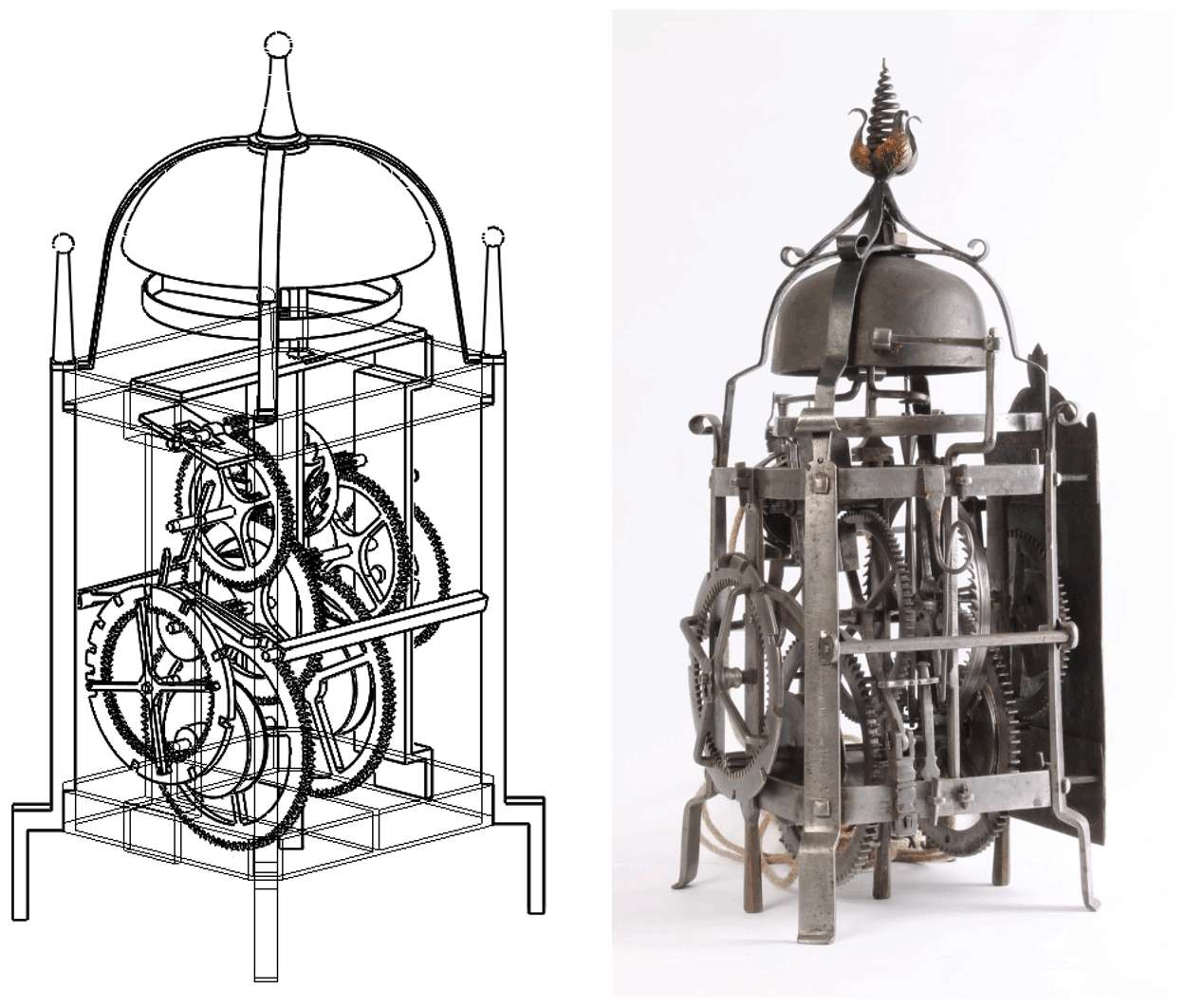
Figure 13N4 – South-German iron Gothic clock (Toebosch Antiques, 2022).
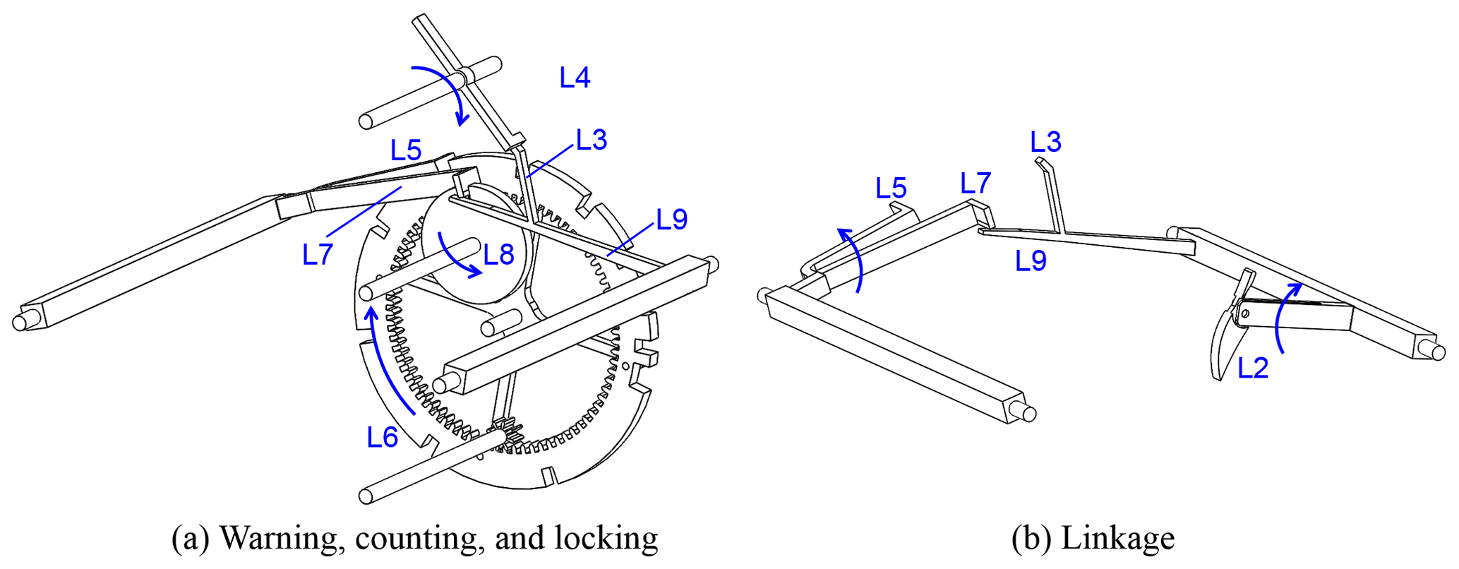
Figure 14Structure and operation of the N4 striking trigger. (The trigger is similar to that of N2.)
N5 – South-German iron chamber clock
Clock N5 is a South-German iron chamber clock manufactured in 1600. Its going system, as shown in Fig. 15, uses a foliot and verge type similar to that of N2. The striking-system configuration is Type 1–2, which is similar in mechanism to N2. However, the cam of L8 has two notches because the velocity ratio of the striking train is different from N2. It is so designed that for every half turn that the locking cam (L8) takes, the count wheel (S6) moves one tooth.

Figure 15N5 – South-German iron chamber clock (Gude & Meis, 2022).
The N5 trigger mechanism, as shown in Fig. 16, is vastly different from N2. This design difference, especially in the trigger and warning mechanism, might be due to the influence of the English lantern clock. In this setup, L1, in the form of a star wheel, is instead positioned on the hour-hand wheel shaft, and the trigger works like a ratchet and pawl; thus L2 is a pawl-shaped lever. The number of teeth on the star wheel is related to the number of rotations of the hour-hand wheel. In N5, every hour the star wheel moves one tooth, as in Fig. 16a. The warning function of L3 and L4 is shown in Fig. 16b. Lever L4 is a pin positioned on the second speed-increasing gear, and the L3 stopper is shaped to stop the pin on L4, which moves in a counter-clockwise direction.
The linkage is shown in Fig. 16d. Both L5 and L7 are on the same lever, while L2, L3, and L7 (L5) are on the same axis and move in unison. The linkage thus consists of only one lever. This is Linkage Type 4, which was also commonly used in a Type 1–2 striking-system configuration after 1600. This trigger mechanism was also common in European iron chamber clocks after about 1600.
N6 – Central European iron chamber clock
N6 is a Central European iron chamber clock, which, according to historical data, was made in the 16th century. Its going system uses a balance wheel and verge type, which is the same as that of N3. However, the structure of the balance wheel is more complicated, as shown in Fig. 17. The striking-system configuration is Type 2–2, which is a rare configuration, and its simplified diagram is shown in Fig. 6d. Because L8 is a cam attached to the outer surface of the speed-increasing gear and adjacent to the count wheel, N6 is a variant of Type 2–2. It is very similar to Type 1–2, except for the placement of the speed-increasing gear. However, this placement has little effect on the type of trigger, except that in the linkage, L3, L5, and L7 cannot be positioned on the same lever as in Linkage Type 1 and Linkage Type 2.
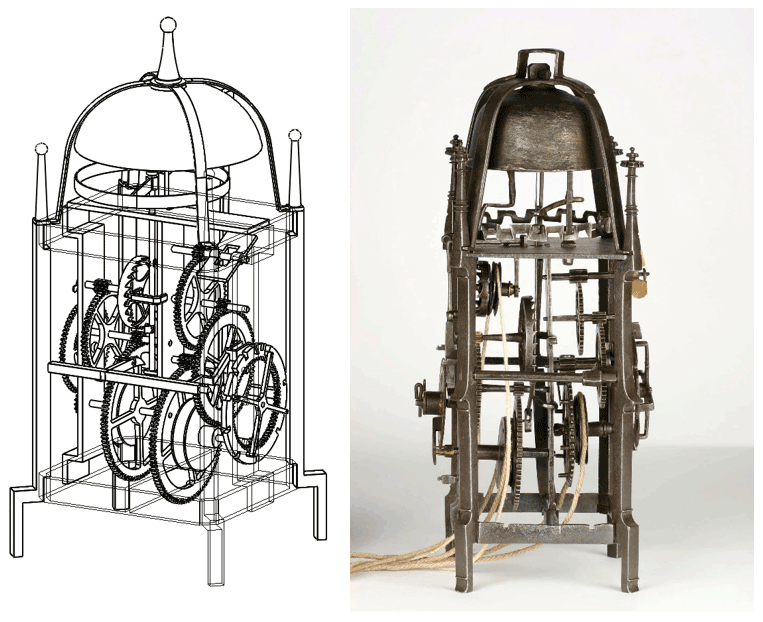
Figure 17N6 – Central European iron chamber clock (German Watch Museum Furtwangen, 2022).
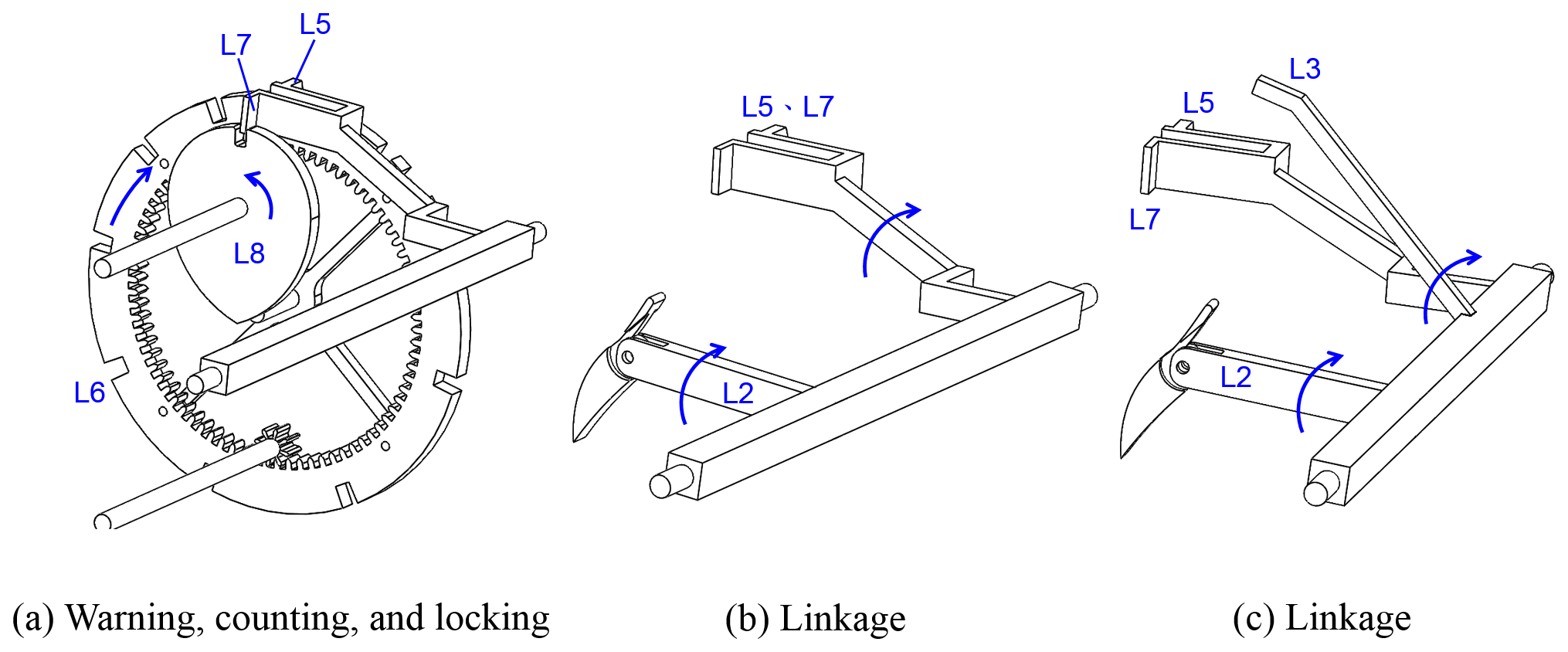
Figure 18Structure and operation of the N6 trigger mechanism. (The trigger is similar to that of N2.)
The trigger is shown in Fig. 18. Because the warning function cannot be observed to be present from Fig. 17, this function is not indicated in Fig. 18b; as such, the trigger only consists of one lever. If a warning function were to be added, the mechanism will be as shown in Fig. 18c. This is Linkage Type 5, which could be used in a Type 2–2 or Type 1–2 striking-system configuration.
N7 – Flemish Gothic clock
Clock N7 is a Flemish Gothic clock (Germany), which, according to historical data, was made during the 16th century. Its going system, as shown in Fig. 19, uses a foliot and verge type, which is the same as that of N2. The striking-system configuration is Type 3–1, which is a rare configuration, and its simplified diagram is shown in Fig. 6e. The count wheel and speed-increasing gear are positioned on the inner side, while L8 is a hoop wheel affixed on the speed-increasing gear.
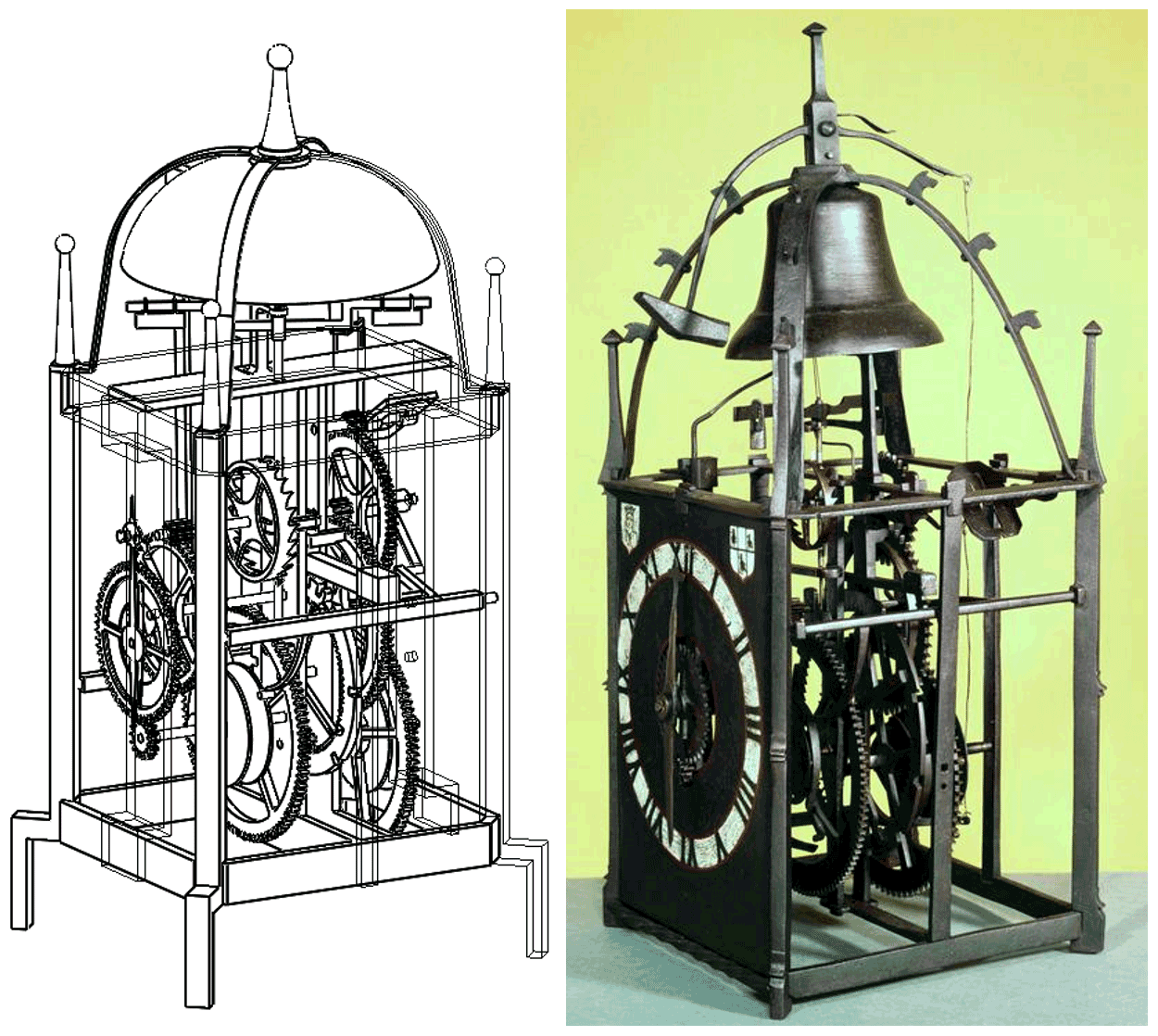
Figure 19N7 – German iron chamber clock (Science Museum, 2022a).
The trigger is shown in Fig. 20. Lever L1, a pin attached to the great wheel in the going train, is used to move and lift L2. Both L3 and L2, which are on the same lever and move in unison, work in conjunction with L4 to provide warning; L4 is a crank attached to the speed-increasing pinion shaft. The N7 linkage is shown in Fig. 20c. Both L5 and L7 are on the same lever, but the two and L2 are on different levers and are positioned on opposite sides; L9, L2, and L3 are on the same lever and move in unison, with L9 working to lift L5 and L7. The linkage thus consists of two levers. This is Linkage Type 6, which is a configuration that could be used in a Type 3–1 striking-system configuration.
N8 – English lantern clock (Peter Closon)
Clock N8 is an English lantern clock (Peter Closon) made around 1630–1640. Its going system, as shown in Figs. 21 and 22, uses a balance wheel and verge type, the mechanism and installation of which is slightly different from the European iron chamber clock such as N3. The striking-system configuration is Type 2–1, where both the count wheel and speed-increasing gear are positioned at the outer side. The count wheel is a spur wheel with notches at its outer rim; thus it moves in an opposite direction to the rope pulley. Lever L8 is a hoop wheel affixed on the speed-increasing gear, and it moves in the same direction as the count wheel.

Figure 21N8 – Lantern clock (Peter Closon) (British Museum, 2020e).
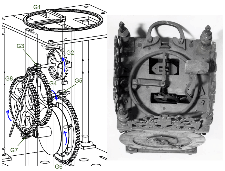
Figure 22Structure and operation of the N8 going system (British Museum, 2020e).
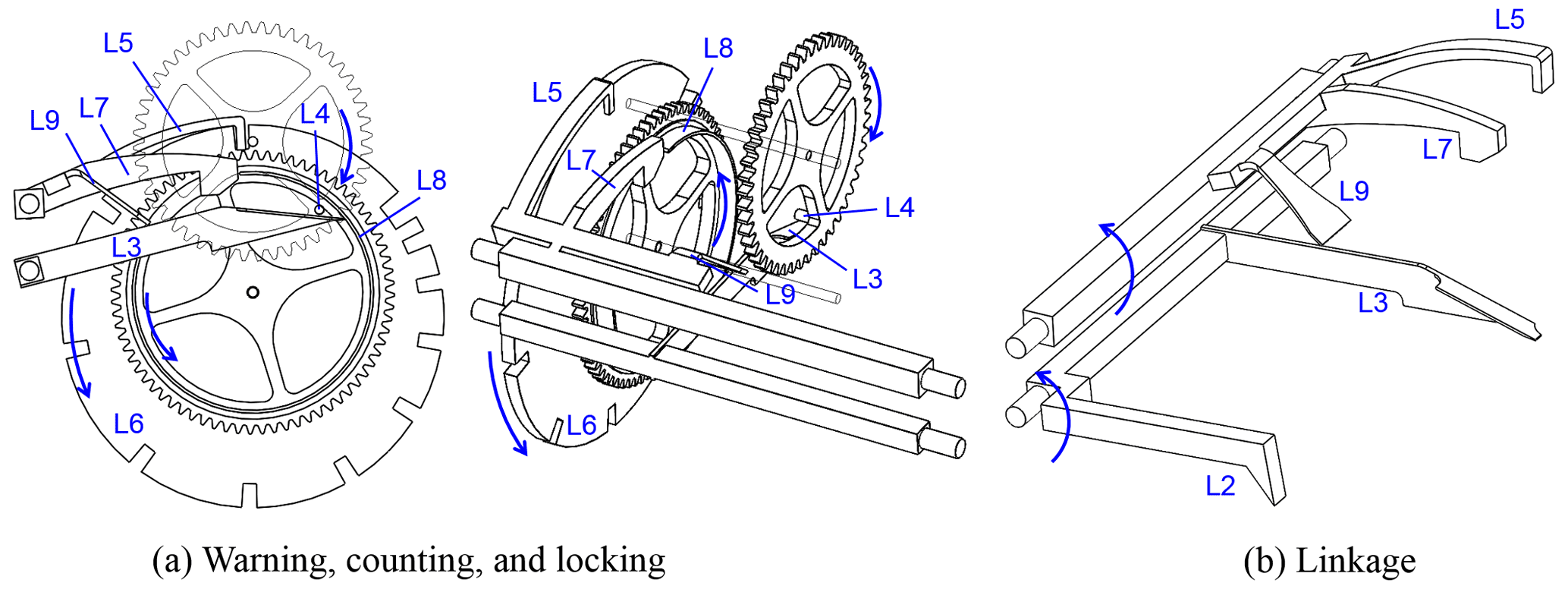
Figure 23Structure and operation of the N8 striking trigger. (The trigger is similar to that of N5.)
The N8 trigger is shown in Fig. 23, and its trigger and warning mechanisms are the same as that of N5. The linkage is shown in Fig. 23b; L5, L7 and L9 are on the same lever, L2 and L5 are on different levers but on the same side, while L2 and L3 are on the same axis and move in unison; L3 moves to lift L9 (including L5, L7). The linkage thus consists of two levers. This is Linkage Type 7, which is most commonly used in a Type 2–1 striking-system configuration.
N9 – German lantern clock
Clock N9 is a German lantern clock manufactured around the end of the 16th century. As shown in Figs. 24 and 25, its going system uses a pendulum and verge type. The short pendulum is positioned at the inside of the frame toward the rear, and the verge and crown wheel are mounted horizontally on the top plate. There is also an additional set of gears (GB1+GB2). The simplified diagram is shown in Fig. 5c. The striking-system configuration is Type 1–2, which is different from typical English lantern clocks, which used Type 2–1. Instead, the striking-system mechanism is the same as the European iron chamber clock (such as N2). However, the cam of L8 has two notches because the velocity ratio of the striking train is different from N2. It is so designed that for every half turn that the locking cam (L8) takes, the count wheel (S6) moves one tooth.

Figure 24N9 – Lantern clock (James Markwick) (British Museum, 2020a).
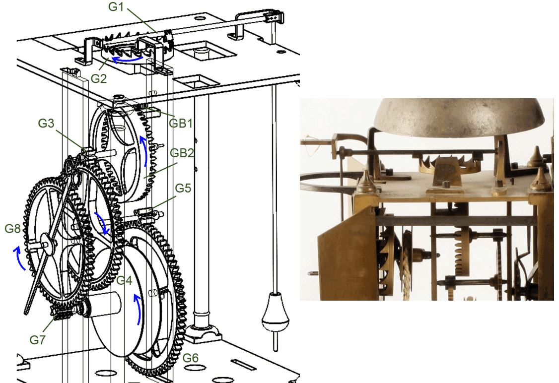
Figure 25Structure and operation of the N9 going system (Artlistings, 2022b). (The photograph is an illustration of a similar type.)
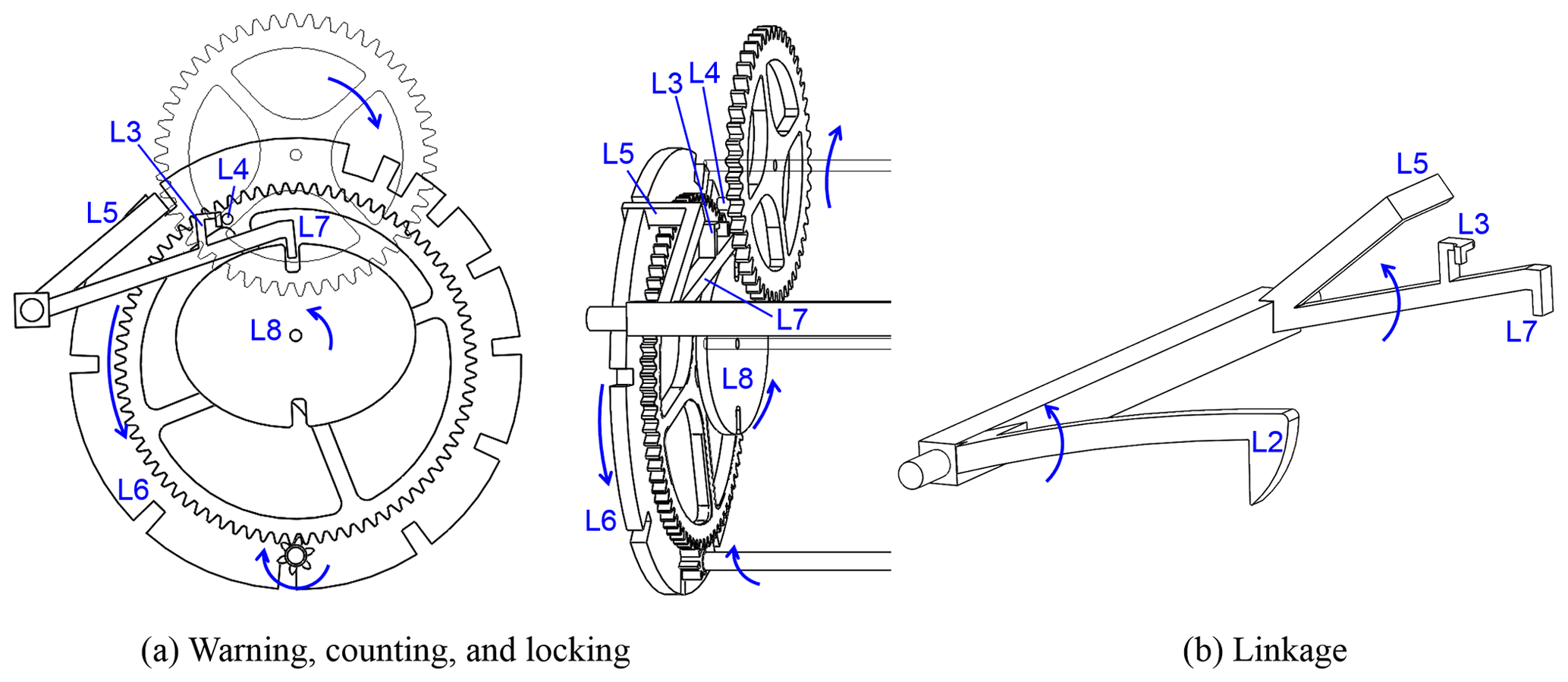
Figure 26Structure and operation of the N9 striking trigger. (The trigger is similar to that of N5.)
The trigger is shown in Fig. 26, and its trigger and warning mechanisms are the same as that of N5. The N9 linkage is shown in Fig. 26b; L3, L5 and L7 are on the same lever, while L2 and L5 (L7 and L3) are on another axis and move in unison. Thus the trigger consists of only one lever. This is Linkage Type 1, which was commonly used in a Type 1–2 striking-system configuration.
N10 – English lantern clock (James Markwick)
Clock N10 is an English lantern clock made by James Markwick around 1665–1675. Its going system uses a pendulum and verge type as shown in Fig. 27, which is the same as that in N9. The striking-system configuration is Type 2–1, and the trigger is shown in Fig. 28. The trigger is structurally similar to that of N8, except for the placement of L3, L5, and L7. In N10, L3, L5, and L7 are each on a separate lever, but they still remain on the same axis and move in unison. Therefore, the linkage is a variation of Linkage Type 7, but is classified as Linkage Type 8.
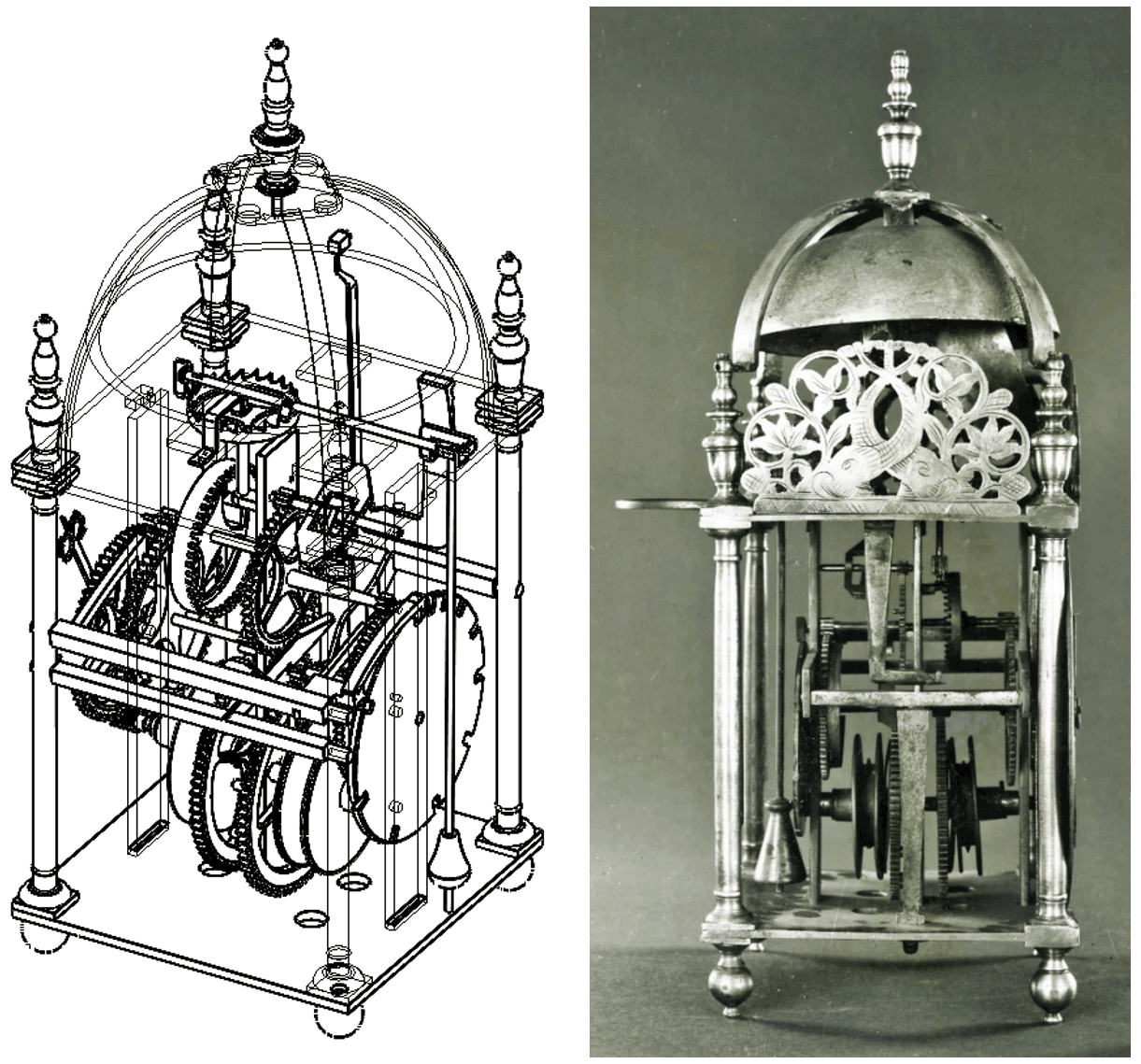
Figure 27N10 – Lantern clock (James Markwick) (British Museum, 2020d).
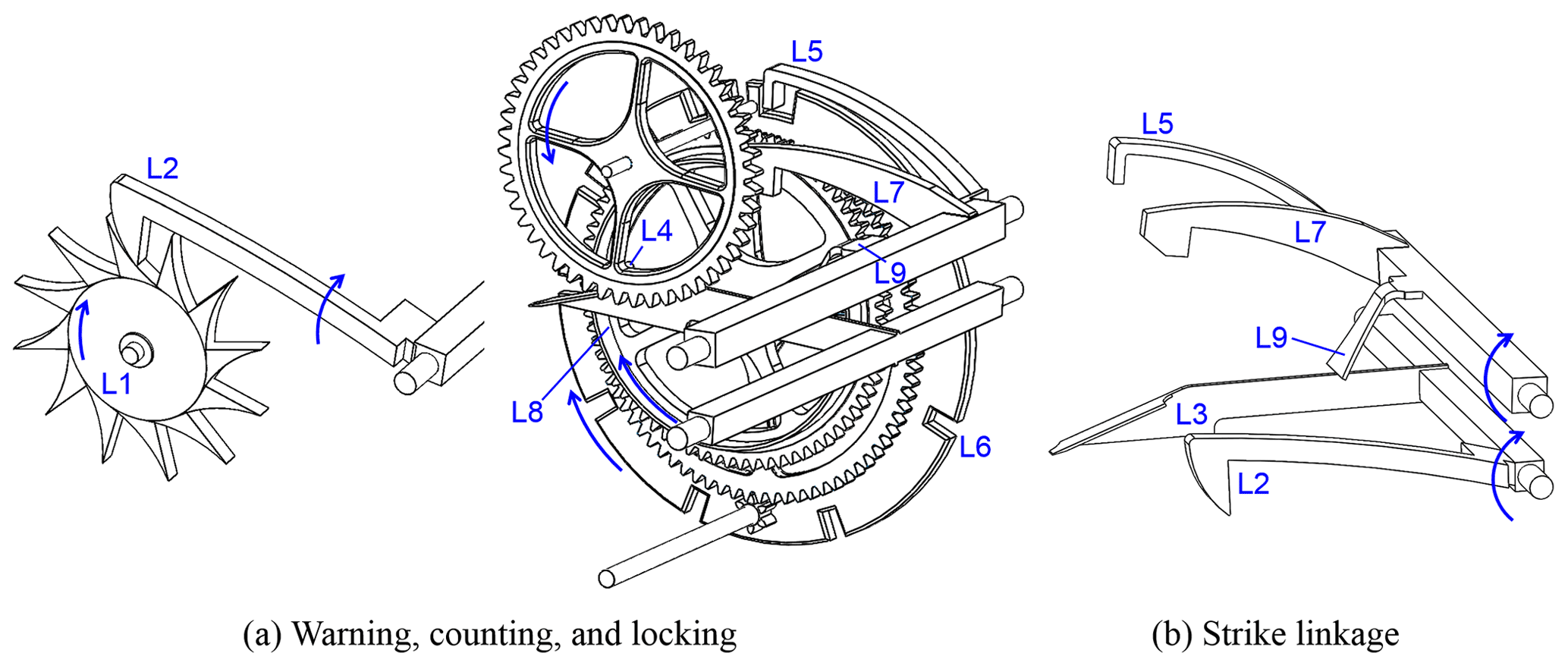
Figure 28Structure and operation of the N10 striking trigger. (The trigger is similar to that of N5.)
N11 – London lantern clock (Thomas Taylor)
Clock N11 is a London lantern clock (Thomas Taylor) made around the 1680s. Its going system uses a pendulum and verge type, which is the same as that of N9. However, the short pendulum is installed at the center of the movement and is referred to as a center-verge pendulum, as shown in Fig. 29. The striking-system configuration is Type 2–1, which is the same as that of N8. Thus, it also uses Linkage Type 7.

Figure 29N11 – Lantern clock (Thomas Taylor) (Artlistings, 2022a).
N12 – Italian lantern Clock
Clock N12 is an Italian lantern clock manufactured around 1721. Its going system shown in Fig. 30 uses a pendulum and verge type, which is the same as that of N9. Its striking system configuration is Type 2–2, which has the same mechanism as that of N6. The N12 trigger, shown in Fig. 31, is similar in mechanism to that of N5. However, the warning mechanism is different; L4 is a gear, which is the second speed-increasing gear, while L3 is a pawl. The linkage is shown in Fig. 31b. While L5 and L7 are on the same lever, L2, L3, and L5 (L7) are on the same axis and move in unison. The linkage thus consists of only one lever. This is Linkage Type 9, which was also used in a Type 2–2 striking-system configuration.
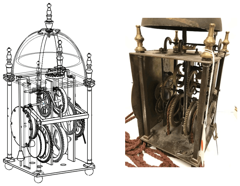
Figure 30N12 – Italian lantern clock (Bonhams, 2022a).
Figure 31Structure and operation of the N12 trigger mechanism. (The trigger is similar to that of N5.)
N13 – London lantern clock (Peter Closon)
Clock N13 is a London lantern clock (Peter Closon) manufactured around the second half of the 17th century. Its going system uses a pendulum and anchor type, with the long pendulum suspended at the outside of the back of the frame using a spring. The teeth of the anchor escapement push against a fork that moves the pendulum and anchor, as shown in Figs. 32 and 33. The simplified diagram is shown in Fig. 5d. The striking-system configuration is Type 2–1, and because its mechanism is the same as that of N8, Linkage Type 7 is used.
Figure 32N13 – London lantern clock (Thomas Taylor Holborne) (Bonhams, 2022b).
Figure 33Structure and operation of the N13 going system (Bonhams, 2022b).
Figure 34N14: Structure of the Italian chamber clock (British Museum, 2020b).
N14 – Italian chamber clock
Clock N14 is an Italian chamber clock manufactured in the 16th century. Its going system uses a foliot and verge type, the structure and installation of which are similar to N2, as shown in Fig. 34. The striking-system configuration is Type 5–1, where the count wheel and the arbor of the rope pulley are perpendicular to each other. (The count wheel and the great wheel are perpendicular to each other.) The count wheel is a spur gear with its teeth projecting radially, and the notches are distributed along its inner rim. The speed-increasing gear is positioned at the movement's outer side (away from the movement's center). Lever L8 is a hoop wheel affixed to the speed-increasing gear, and its movement is opposite that of the rope pulley.
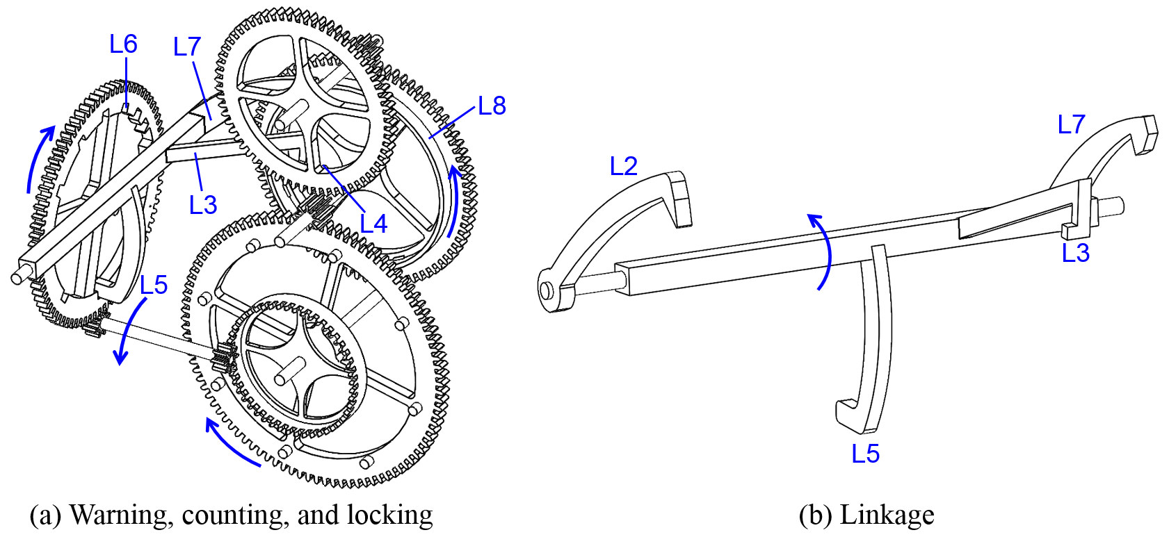
Figure 35Structure and operation of the N14 trigger mechanism. (The trigger is similar to that of N5.)
The trigger is shown in Fig. 35. Its warning and trigger mechanisms are the same as that of N5. The N14 linkage is shown in Fig. 35b; L2, L3, L5 and L7 are levers along the same axis and move in unison. The linkage thus consists of only one lever. Lever L5 points downward and matches with the notches (L6) at the inner rim of the count wheel. When L5 falls into a notch at L6, L7 will also fall into a notch at L8; at this point, the linkage is lowered to its lowest point. This is Linkage Type 10, which was used in a Type 5–1 striking-system configuration.
The study analyzed the mechanism of 14 representative chamber clocks listed in Table 1. Results show that only two types of going systems were used in early European iron chamber (Gothic) clocks: (1) foliot and verge type and (2) balance wheel and verge type. Although there were many types of accompanying striking systems, Table 1 shows that most were Type 1–2, a few were Types 2–2, 3–1, and 5–1; no Types 3–2, 4–1, 4–2, and 5–2 were found. In addition, the corresponding linkage mechanisms were primarily Linkage Type 1 and Linkage Type 2, and thus N2 and N3 were the main types of early chamber clocks. By 1600, English lantern clocks became the mainstream. The going systems of early English lantern clocks used balance wheel and verge type, while the striking-system configurations were primarily Type 2–1. After 1658, pendulum and verge type as well as pendulum and anchor type became the mainstream for going trains. Striking-system configurations were primarily Type 2–1, and the corresponding linkage mechanisms were mostly Linkage Type 7 and Linkage Type 8. Thus, N8, N10, and N13 were representative of the early English lantern clocks.
In this study, we used the method of mechanical evolution and variation, analyzed and compared clock movements based on historical data and existing clocks, and synthesized 40 possible movement configurations of early-day chamber clocks. A total of 4 going-system configurations (including foliot and verge, balance wheel and verge, pendulum and verge, and pendulum and anchor) and 10 striking-system configurations (including 5 striking-train types and 2 locking-detent positions) were identified. In addition, 14 existing representative chamber clocks were used as examples and their mechanism analyzed to illustrate the above configurations and their variations. The study results showed that there were many variations in the design of the linkages and levers in the striking-system configuration. A total of 10 configurations were identified in this study, which could help in the creation of a comprehensive atlas of the movement designs. The results can not only help to systematically carry out the reconstruction design of various chamber clocks, but also provide new information for scholars of history of science to further historical research and develop new materials for creativity, science and technology education.
The data are available upon request from the corresponding author.
WFL was responsible for collecting the research literature, organizing the paper structure, and writing the paper. TYL provided the research direction of this paper, together with suggestions for the revision and correction of the paper.
The contact author has declared that neither of the authors has any competing interests.
Publisher's note: Copernicus Publications remains neutral with regard to jurisdictional claims in published maps and institutional affiliations.
The authors are grateful to the Ministry of Science and Technology (Taiwan, ROC; grant no. NSC 100-2221-E-006-065-MY3), for the support of this work.
This research has been supported by the Ministry of Science and Technology, Taiwan (grant no. NSC 100-2221-E-006-065-MY3).
This paper was edited by Daniel Condurache and reviewed by two anonymous referees.
Andrewes, J. H.: A chronicle of timekeeping, Sci. Am., 278, 76–85, 2002.
Artlistings: https://www.artlistings.com/Clocks/Lantern-clocks/An-English-brass-lantern-clock-with-wings.-Thomas-Taylor-Holborne-London.-circa-1680, last access: 10 January 2022a.
Artlistings: https://www.artlistings.com/Clocks/Lantern-clocks/A-well-engraved-French-brass-alarm-lantern-timepiece.-circa-1740, last access: 10 January 2022b.
Bonhams: https://www.bonhams.com/auctions/25473/lot/70/, last access: 10 January 2022a.
Bonhams: https://www.bonhams.com/auctions/24663/lot/50/?category=list, last access: 10 January 2022b.
Brian Loomes: https://www.brianloomes.com/collecting/lanternbegin/bobpendulum.html, last access: 2 March 2022.
Bridgemanimages: https://www.bridgemanimages.com/en-US/noartistknown/clocks-domestic-general-liechti-iron-chamber-clock-1596/object/asset/5061456, last access: 6 January 2022.
British Museum: https://www.britishmuseum.org/collection/object/H_1888-1201-127, last access: 23 November 2020a.
British Museum: https://www.britishmuseum.org/collection/object/H_1958-1006-2093, last access: 17 February 2020b.
British Museum: https://www.britishmuseum.org/collection/object/H_1958-1006-2094, last access: 23 November 2020c.
British Museum: https://www.britishmuseum.org/collection/object/H_1958-1006-2095, last access: 23 November 2020d.
British Museum: https://www.britishmuseum.org/collection/object/H_1958-1006-2145, last access: 23 November 2020e.
British Museum: https://www.britishmuseum.org/collection/object/H_1967-0601-1, last access: 23 November 2020f.
British Museum: https://www.britishmuseum.org/collection/object/H_2015-8041-5, last access: 23 June 2020g.
German Watch Museum Furtwangen: https://bawue.museum-digital.de/object/29725, last access: 10 January 2022.
Gude & Meis: https://gudemeis.com/en/collectie/a-large-south-german-gothic-polychrome-painted-iron-wall-clock-circa-1600/, last access: 10 January 2022.
Liang, Z. J. and Liang, S.: A New Angle of View in Machinery History Studies – Drawing Up Evolution Pedigree and Innovation, Proceedings of 2000 HMM International Symposium on History of Machines and Mechanisms, edited by: Ceccarelli, M., Springer, Switzerland, 283–290, https://doi.org/10.1007/978-94-015-9554-4_32, 2000.
Liang, Z. J. and Shu, L.: A general reference proven system for study machinery evolution history – linkage of history and innovation, Proceedings of the sixth China–Japan International Conference on History of Mechanical Technology and Mechanical Design, 29 October 2006, Beijing, China, 50–56, 2006.
Lin, T. Y.: SHUIYUN SHIZHUAN – ZHONGGUO GUDAI QINZONG TIAOSUQI ZHI XITONGHUA FUYUAN SHEJI, edited by: Zhang, B. C., Shandong Education Press, Jinan, China, 3–6, ISBN 9787570109678, 2020.
National Trust for Scotland: https://www.nts.org.uk/stories/time-stands-still, last access: 17 February 2020.
Robey, J. A.: A Large European Iron Chamber Clock, Antiquarian Horology, 33, 335–346, 2012.
Robey, J. A.: The origin of the English lantern clock Part 1: Comparison with European Gothic clocks, Antiquarian Horology, 37, 511–521, 2016.
Robey, J. A.: An early Gothic Hausuhr, Antiquarian Horology, 39, 475–484, 2018.
Robey, J. and Gillibrand, L.: The Porrvis Clock of 1567 — The Earliest Surviving Domestic Clock Made in England, Antiquarian Horology, 34, 503–518, 2013.
Science museum: https://collection.sciencemuseumgroup.org.uk/objects/co795/german-16th-century-iron-chamber-clock-gothic-clock-weight-driven-balance-wheel-clock, last access: 5 January 2022a.
Science museum: https://collection.sciencemuseum.org.uk/objects/co531, last access: 5 January 2022b.
Teng, H. F., Zeng, W., Liang, D. W., Sun, Z. G., Liu, J., and Li, G. Q.: Evolutionary design method and its application, Chin. J. Mech. Eng., 40, 1–5, 2004.
Thompson, D.: Clocks, British Museum Press, London, 20, ISBN 9780714128122, 2004.
Toebosch Antiques: https://www.toeboschantiques.com/Clocks/Wall-clocks/A-South-German-iron-striking-renaissance-chamber-clock-with-alarm.-dated-1608, last access: 10 January 2022.
Wikipedia: https://en.wikipedia.org/wiki/Lantern_clock, last access: 23 November 2019.
Yan, H. S.: An Approach for the Reconstruction Synthesis of Lost Ancient Chinese Mechanisms, Proceedings of 2008 HMM International Symposium on History of Machines and Mechanisms, edited by: Yan, H. S. and Ceccarelli, M., Springer, Switzerland, 325–336, https://doi.org/10.1007/978-1-4020-9485-9_23, 2009.
- Abstract
- Motivation and research objective
- Limitations of the study and sampling
- Typical chamber clock movement: N2 Liechti iron chamber clock (1596)
- Possible movement configurations of early-day chamber clocks
- Structural analyses of existing chamber clocks
- Conclusions
- Data availability
- Author contributions
- Competing interests
- Disclaimer
- Acknowledgements
- Financial support
- Review statement
- References