the Creative Commons Attribution 4.0 License.
the Creative Commons Attribution 4.0 License.
 | 30 Aug 2022
Dynamic and sliding mode control of space netted pocket system capturing and attitude maneuver non-cooperative target
Chao Tang
Zhuoran Huang
Cheng Wei
Yang Zhao
Similar to a space flying net, the capture field of the space netted pocket system is large and it can be applied to capture space non-cooperative targets flexibly. To maintain the stability of the space netted pocket system, eight inflatable rods are used as the supporting structure of the net surface. In this paper, a space netted pocket system is designed and modeled. Based on ANCF (absolute nodal coordinate formulation), a dynamic model of the complex space rope net system is established, and then an accurate model of closing rope considering the variable length is derived by introducing mass flow element. A double closed-loop sliding control method is designed to maintain the stable attitude of the service spacecraft. An extended observer is applied to estimate and compensate for the disturbances due to the uncertainty of the contact and flexibility in the system. Finally, the dynamic model and control method is verified through the simulation of the virtual prototype. Results show that the service spacecraft can maintain the attitude stability during target captured process and can track the desired angle during attitude maneuver. The flexible deformation and collision cause great disturbance to the service spacecraft, and the extended observer can improve the control accuracy from 10−3 to 10−4.
- Article
(4322 KB) - Full-text XML
- BibTeX
- EndNote


In recent years, with the increase of human space activities, threats to space activities from space debris are worsening (Barmin et al., 2014; Chen, 2011). The contact capture method is a simple and feasible way to capture space debris. There are mainly two types of contact capture: rigid capture and flexible capture (Nishida and Kawamoto, 2011; Shan et al., 2016). Like space manipulator and capture claw, the rigid capture methods will inevitably cause collision between the capture target and operation platform. Therefore, the rigid capture methods are more complicated and require high control accuracy. The space net as a typical flexible acquisition method is more lightweight and simple (Zhang et al., 2017). The capture domain of the space net is larger, which can reduce the control accuracy requirements and reduce the cost. Therefore, the space net is an active space debris removal method with broad application prospects.
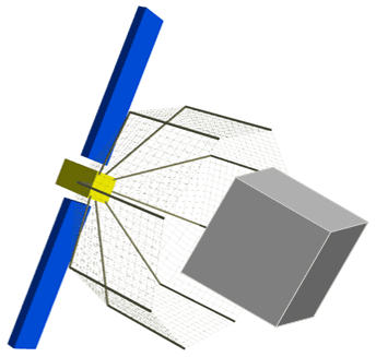
The space fly net launches a flexible rope net to cover the space debris in a large envelope and drags space debris to the atmosphere burned or grave orbit. In recent years, a lot of theoretical and experimental researches has been carried out around the space fly net. In terms of large-scale experiments, RemoveDEBRIS project has now completed the first space rope net capture test in orbit (Forshaw et al., 2016, 2017) and e.Deorbit project has carried out parabolic flight test (Biesbroek et al., 2017). At the same time, many theories about space net dynamics modeling, space net deployment control, space net capture performance analysis and space net structure optimization design are deeply researched (Bonnal et al., 2013; Ming et al., 2017; Xu et al., 2019). However, it is difficult for the fly net system to maintain the net shape fully deployed for a long time. And the capture success rate will be reduced due to the space fly net hardly maintaining the net shape for a long time. Some scholars have proposed the motorized fly net to control the net shape (Huang et al., 2015; Meng et al., 2017), but multiple motorized devices around the net will greatly increase the complexity and cost of the system. The space rope netted pocket capture mechanism described in this paper can inherit the advantages of lightness and simplicity. Furthermore, the inflatable rods in the system can maintain the net shape for a long time, which can improve the success rate of capture. The rope net surface of the netted pocket capture mechanism in Fig. 1 is supported in an umbrella-like shape by eight flexible rods. First, the service spacecraft approaches the captured target until the target enters the net. Second, the closing devices at the end of inflatable rods are tightened to complete the closing. Finally, with attitude maneuver of the service spacecraft, the space netted pocket drags the captured target to change orbit.
Due to the strong nonlinearity dynamics of the net and the large uncertainty of the target, the precise control of the rope net spacecraft is more difficult. The traditional PD (proportional differential) controller can hardly meet the accuracy requirements of the mission. For the stability control of tethered satellites, Huang et al. considered the effect of the flexibility of rope, and designed an adaptive control method to achieve attitude stability control of combinations with unknown parameters (Huang et al., 2016); Wei et al. (2019) designed a spacecraft attitude stability ADRC (active disturbance rejection control) controller which can estimate and compensate uncertainties of system parameters in real time (Wei et al., 2019).
However, the current research generally only focuses on the attitude control during capture or maneuver, and the process of capture and maneuver is not continuous. Moreover, the dynamic model and simulation prototype for controller verification is imperfect, which cannot simulate the nonlinear properties and contact collision of the rope accurately. So, it is untrue to verify controllers using the imperfect dynamic model for the space netted pocket system.
To solve these problems, this paper designs an extended observer to compensate the uncertainty and disturbance of the model based on the principle of active disturbance rejection control (ADRC). Combined with the robust sliding mode control method, the attitude controller of the service spacecraft is constructed. At the same time, a complex dynamic model of the net pocket system is established based on the dynamic theories such as variable flexible cable, ANCF (absolute nodal coordinate formulation) and collision theory. The closed-loop simulation of dynamics and control can be completed through the virtual simulation prototype.
2.1 Netted pocket system composition and size design
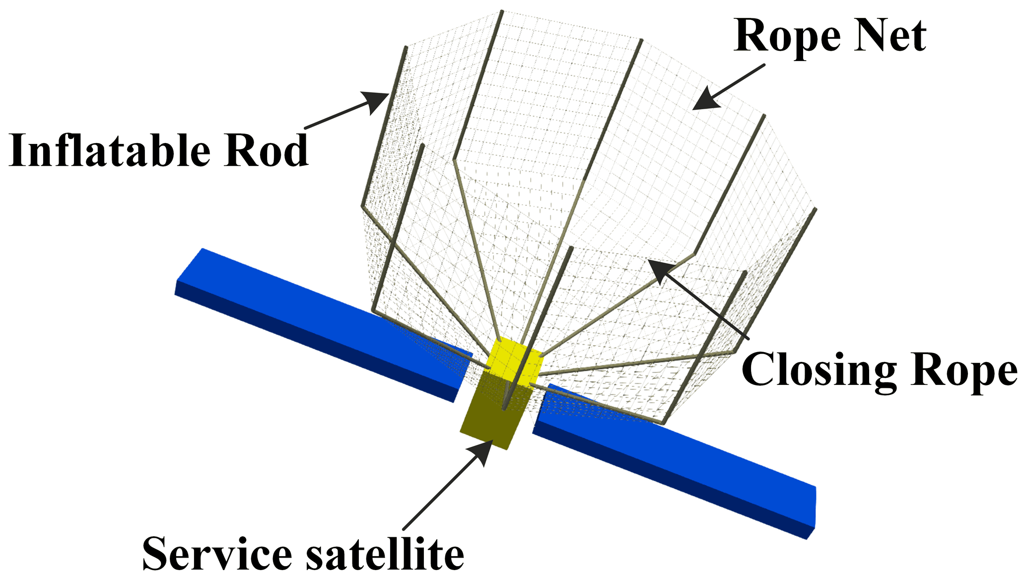
As shown in Fig. 2, the netted pocket system consists of eight flexible support inflatable rods, which are connected by rope net. The inflatable rods are evenly distributed in a positive octagonal shape, with a single rod diameter of 0.1 m. The rope-retracting mechanism at the end of each rod pulls the rope to close the net. The size and braided shape of the single net piece between support rods are designed as shown in Fig. 3. The upper part of the square rope net is 14×12 (row × column) configuration and the lower part of the triangular rope net is 10×12 (row × column) configuration. The maximum diameter of the net pocket is 15.12 m and the maximum depth is 12 m.

2.2 Dynamic model of the space netted pocket
2.2.1 Dynamic model of the closing ropes based on variable flexible ropes
A rope retractor is installed at the end of each inflatable rod, and the diameter of the opened net is adjusted by controlling the length of the closing rope. Due to the rope retractor, the system structure is complex, and it is difficult to simulate the ropes inside and outside the retractor at the same time. In this case, the simulation takes a long time, and the rope inside the retractor has little impact on the rope net capture system. Therefore, in order to simplify the dynamic model of the rope net capture device and improve the simulation speed, this paper establishes the dynamic model of closing ropes based on the ANCF flexible cable dynamics model. Using v1 as the mass flow velocity at the element boundary node, the variable length flexible cable element model of the closing rope is established in Fig. 4.
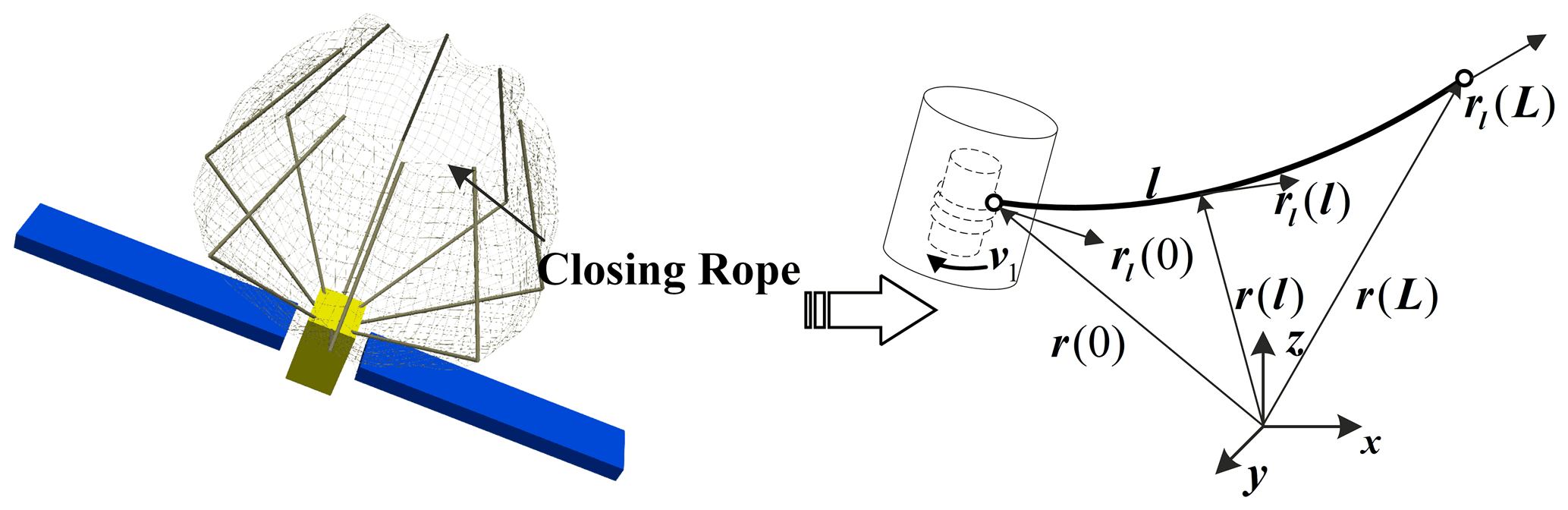
Based on ANCF, the generalized coordinates of flexible cable element jq can be expressed as
where jrT(0) and jrT(L) are the position vector of nodes at both ends of the element; and and are the gradient vector nodes at both ends of the element. And the position vector jr(l) of any node on the central axis of the element can be written as
where S(l) is the shape function; ξ can be written as follows:
The length of the rope element L(t) and the position of the particle l(t) are time variables, so the variable length element shape function S(l,t) is a function of time. Then the velocity and acceleration of any point are expressed as
In the case of varying element length, the Lagrange method is no longer applicable with the assumption of the mass flow at the boundary. The dynamical equations are derived using D'Alembert's principle, which states that the sum of virtual work done by inertial force and acting force on any virtual displacement is 0.
δri is the particle i in any moment to meet the constraints of the virtual displacement. The force on the rope element can be decomposed into elastic force FE and external force Ff, then the dynamics equation of the cable element can be written as
Considering only the axial and bending deformation of the cable, the expression of the virtual work of each part can be written as
where are axial strain and curvature, and E is elasticity modulus. A is the cross-sectional area and J is the moment of inertia of the flexible cable element. c is the damping coefficient and .
Combining Eqs. (10), (11) and (12), the dynamic equation of the variable flexible cable element can be written as
where
Considering a long cable with N−1 flexible elements, only the lengths of the flexible elements at the ends can be varied, while the lengths of the other elements remain constant. The equation for a variable length cable can be obtained by combining the dynamic equations of all the elements.
where q represents the generalized coordinates of the system, consisting of the generalized coordinates of each node. M and Q represent the relative generalized mass matrix and generalized forces of the cable.
2.2.2 Dynamic model of space rope netted system based on ANCF
In Gerstmayr and Shabana (2006), the ANCF equations for the dynamics of the space rope netted system can be expressed as
where M is the mass matrix, q is the generalized coordinates, Qε generalized force vector, C is constraint equation, and U is strain energy. The details in Eq. (17) can also be obtained by taking v1=0 from the variable length flexible cable model.
2.2.3 Contact collision force model
According to the Hertz contact model, the contact force at the collision point consists of the normal collision force Fn and the tangential friction force Ft.
Using the nonlinear spring damping model, the normal collision force is calculated as
where n is the normal unit vector and v is the normal relative velocity. The expressions of kn and gn are as follows:
where reff is the radius of curvature of the contact point, m1 and m2 are the mass of the contact pair, E is the elastic modulus of the material, and other unknown quantities are as follows:
Coulomb friction is used in the tangential direction as follows:
where μ is the coefficient of friction, which is determined by the tangential relative velocity vt.
In the process of catching and towing target, the cable element collides with the target. Based on the principle of virtual work, the contact force can be transformed to a generalized nodal force.
2.3 Attitude dynamics of the service spacecraft
The attitude Euler angle of the service spacecraft can be selected as , then the spacecraft attitude dynamic equation can be written as
where Mc is the control torque of the service spacecraft. is the rotational inertia of the service spacecraft and ω is the angular velocity of the service spacecraft. dq is the system uncertainty terms such as the interference generated by the mutual collision and the large deformation of flexible netted pocket. Ω is the skew–symmetric matrix of the form as follows:
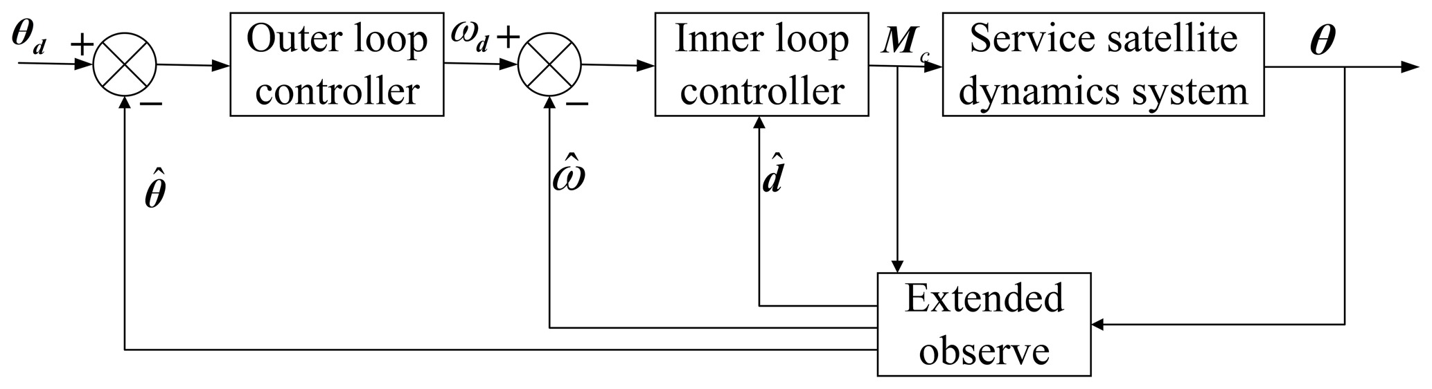
In this paper, the spacecraft attitude controller uses an extended observer to estimate dq, and a two-loop sliding mode control method to design the attitude control torque Mc, which can ensure the service spacecraft attitude θ tracking the desired attitude angle θd. The outer-loop sliding mode control law calculates the attitude angular velocity ωd and transmits ωd to the inner loop; the inner-loop sliding mode control law tracks the attitude angle ωd. The entire two-loop control system is shown in Fig. 5.
3.1 Design of spacecraft attitude extended observer
Based on Eq. (23), the system state equation can be written as
Referring to Freidovich and Khalil (2008), the spacecraft attitude extended observer is designed as
where is the state estimation of θ, is the state estimation of and is the state estimation of . δ is taken as follows:
3.2 Design of outer loop sliding mode control
The integral sliding mode (Liu and Wang, 2011) is adopted to realize the sliding mode surface design. Taking , the sliding mode surface of the outer loop can be written as follows:
where Kw>0 is 3×3 diagonal matrix.
The derivation of Eq. (29) can be obtained as follows:
where and outer loop control law is
where ρw>0. Taking Lyapunov function (Pham et al., 2019), it can be proved that
when the inner loop converges quickly and ωe is sufficiently small. There is and the error eθ is asymptotically stable.
3.3 Design of inner loop sliding mode control
The sliding surface of the inner loop is designed as
where Kn>0 is 3×3 diagonal matrix. The derivation of Eq. (33) can be obtained as follows:
The control law of the inner loop is designed as
where , . To further eliminate the “chattering”, the saturation function sat(s) is used as the switching function.
Taking Lyapunov function, , it can be proved (Slotine and Sastry, 1983) that
The Eq. (36) proves that Vn is exponential convergence.
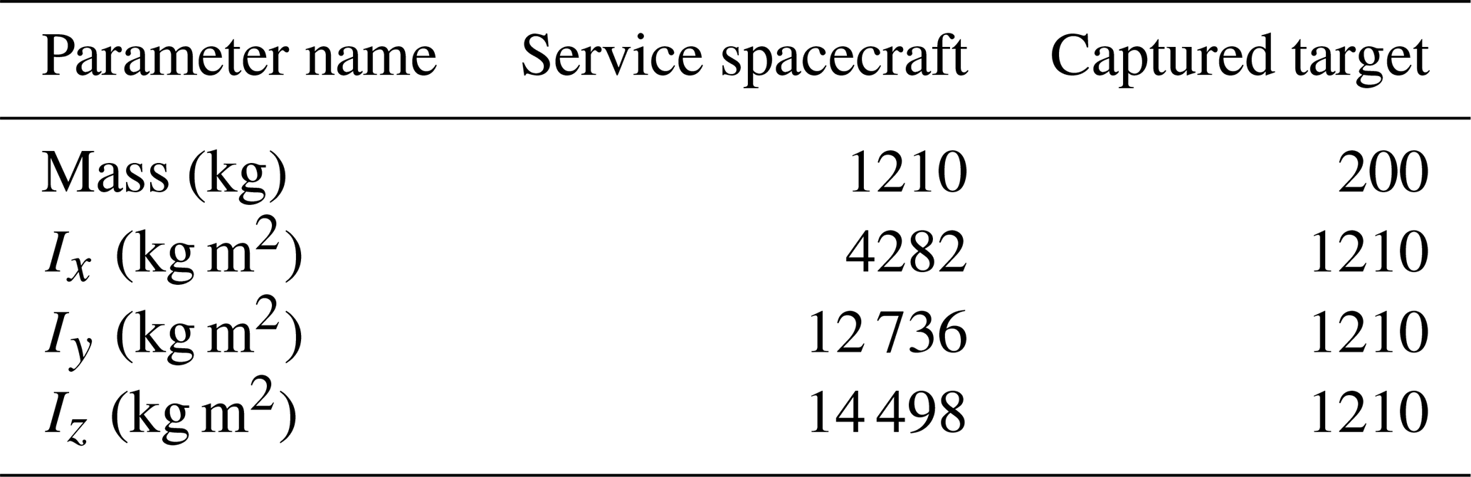
This paper utilizes the multi-body dynamic simulation software (MBDyn) developed by the author's laboratory to perform dynamic simulation. The dynamic parameters of the service spacecraft and captured target are in Table 1.
Table 1The dynamic parameters of the service spacecraft and captured target.
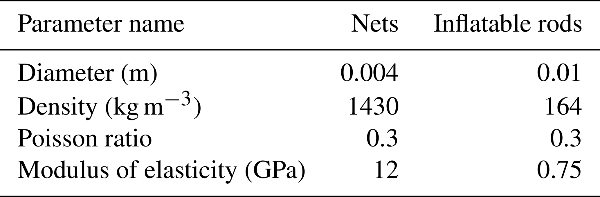
The material parameters of the inflatable deployment rod and rope net are in Table 2.
Table 2The material parameters of the inflatable deployment rod and rope net.
4.1 Service spacecraft attitude maneuvering process simulation
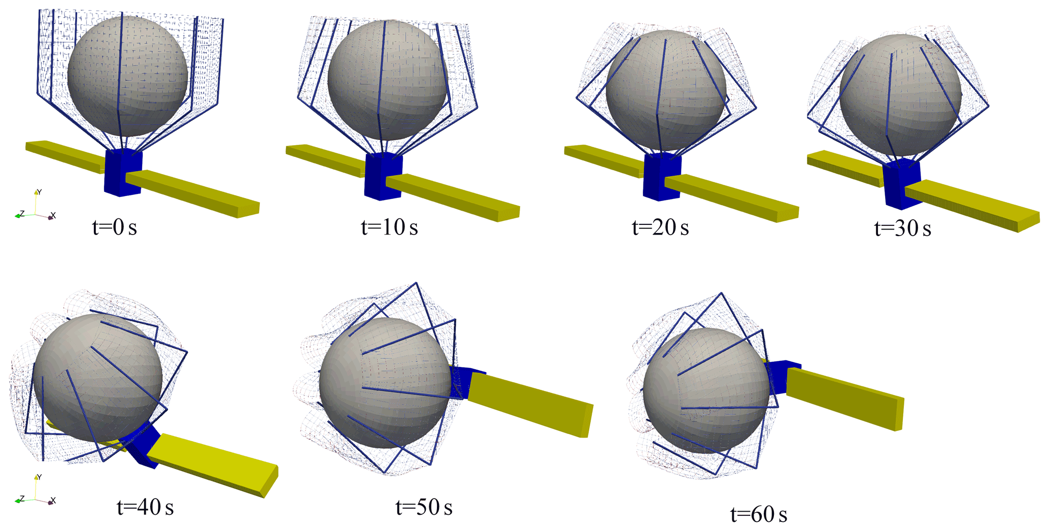
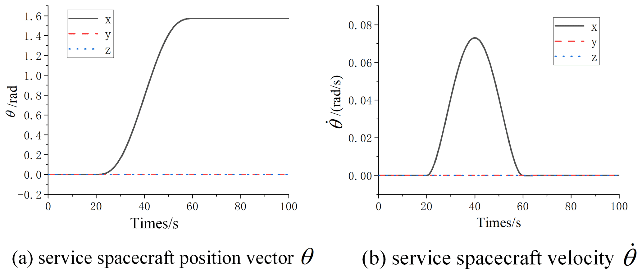
The process of the service spacecraft capture target and attitude maneuver is designed as follows: 0–20 s is the process of net retraction during which the service spacecraft remains stationary; 20–60 s is the process of service spacecraft attitude maneuvering 90∘ around x axis; and 60–100 s is the process of service spacecraft attitude maintenance. In order to ensure the smooth and continuous motion process, the rope retrieval length in the 0–20 s and the spacecraft attitude maneuvering in 20–60 s are planned using the 5 times interpolation, and then the angular velocity and angular acceleration are 0 at 20 and 60 s can be determined.
Set the parameters of the sliding mode controller kw=1, kn=10, ρn=0.01, the parameters in the saturation function Δ=0.5 , and the parameters of the expansion observer R=100. The dynamics and control closed-loop simulation of the attitude maneuvering process is performed, and the calculation results are in Fig. 6.

The estimates of the attitude motion state and disturbance by the expansion observer are shown in Fig. 8. Comparing Figs. 8 and 7, it can be seen that the estimates of the observer are consistent with the motion process, which illustrates the validity of the observations.

As shown in Fig. 9, compared with ordinary sliding mode control, the error of extended observer controller is reduced by 1 order of magnitude. Therefore, the control accuracy of the double-loop sliding mode attitude controller based on the extended observer is significantly higher than the ordinary sliding mode control. It indicates that the extended observer compensates the disturbance effectively, and the service spacecraft attitude controller designed in this paper can meet the stability requirements of the attitude maneuvering process.
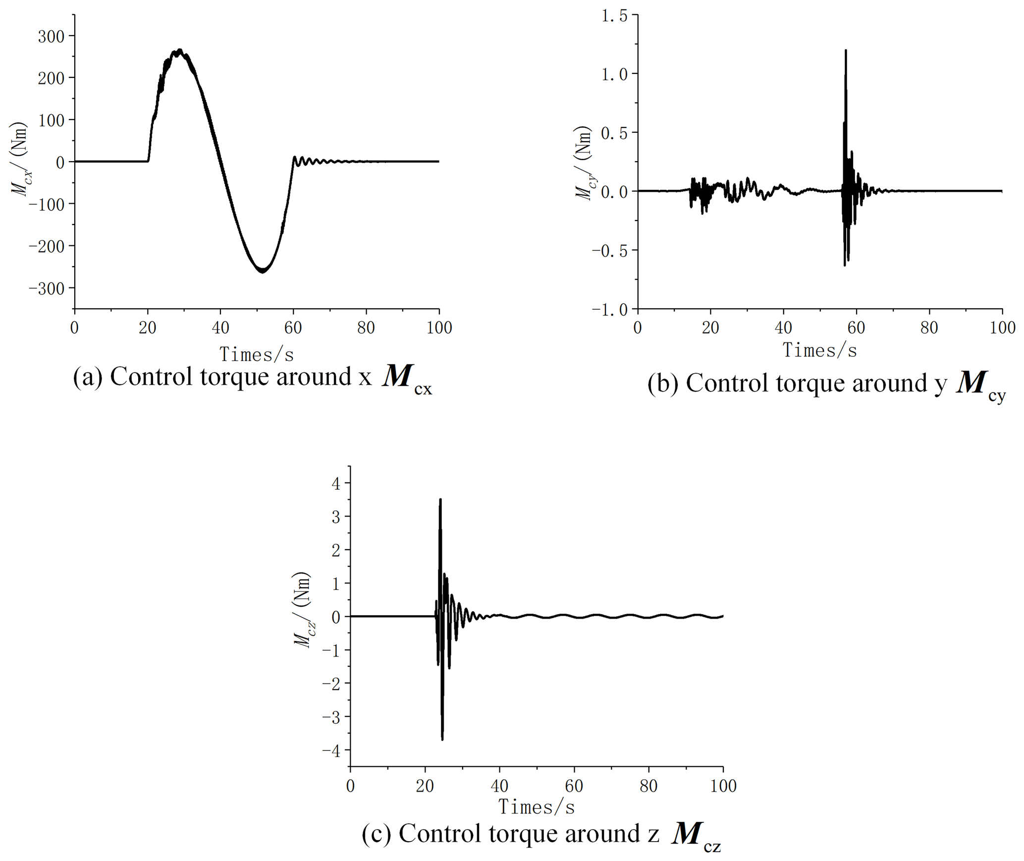
As shown in Fig. 10, the net is a centrosymmetric structure and the initial state of target is located in the center, so the control torque Mc in each direction is small during 0 to 20 s. Due to the collision increases at 20 and 60 s, the control torque produces buffeting. And during 20 to 60 s, the service spacecraft attitude maneuvers around the x axis, so the control torque is much higher than . The flexible structure of the system generates certain perturbations. So, in the attitude holding process after 60 s, the control torque curve still fluctuates until the system stabilizes.
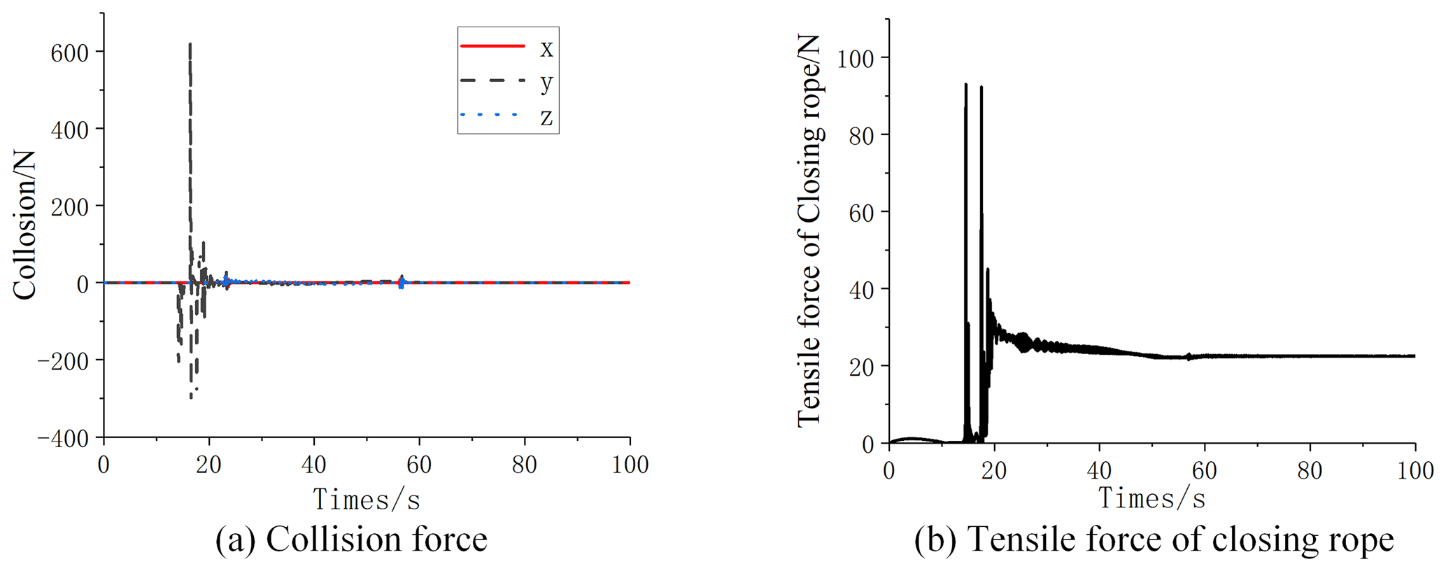
It can be seen from the collision force curve in Fig. 11a that the collision force between the capture target and the rope net is mainly concentrated in the y direction. During 0 to 15 s, tensile force of closing rope is mainly caused by the bending of the inflatable rod, and the value is small as shown in Fig. 11b. During 15 to 20 s, the collision force is large, so the tensile force of closing rope is also with large step. As shown in Fig. 11b, the tension force of the closing rope tends to be stable and non-zero after 20 s, indicating that the rope net is tightly wrapped in the target and there is no relative movement between them. It can also be seen from the collision force curve that the close wrapping of the rope net around the target significantly reduces the collision in the maneuvering process. Thus, the interference is further reduced, and the control torque of spacecraft is facilitated as shown in Fig. 10.
In this paper, the dynamics and stability control of the space net pocket capture and towing process are studied, and the following conclusions are obtained.
-
The dynamic model of the space netted pocket capture system is carried out. Based on the ANCF method, the dynamic model of the space rope system can respond to the large deformation properties of the catching mechanism. Based on the dynamic model of the closing rope established from the ANCF flexible cable theory, the simulation of the non-cooperative target capture process is realized, and the dynamic response of the closing rope recovery can be analyzed.
-
A sliding mode controller based on the extended observer is designed with reference to the service spacecraft dynamic equations. Only the attitude of the spacecraft is needed to complete the maneuver control, as the extended observer can observe the velocity angular velocity of the spacecraft. Moreover, based on spacecraft attitude extended observer, the sliding mode controller can ensure the high accuracy and stable attitude control of the service spacecraft.
-
Closed-loop dynamics and control simulations are performed for the capture and towing process of the service spacecraft. The simulation results can reflect the large deformation of the net pocket and the contact collision between the net pocket and the target during the capture and towing process. The closed-loop simulation results verify that the control accuracy is improved by 1 order of magnitude under the interference compensation of the expansion observer, which is beneficial for realizing the stable attitude control of service spacecrafts with large deformation structure.
The simulation software is jointly developed with a third party. The other party is for commercial purposes and does not want the software code to be disclosed.
In this paper, the simulation conditions and relevant parameter data are listed in Tables 1 and 2. And the effective data results are shown by curves in Figs. 7–11.
CT was mainly responsible for the calculation and data analysis of the simulation examples in this paper. ZH was mainly responsible for the modeling of simulation examples in this paper. CW was mainly responsible for the development of the dynamics software in this paper. YZ was mainly responsible for the research of dynamics and control theory in this paper.
The contact author has declared that none of the authors has any competing interests.
Publisher’s note: Copernicus Publications remains neutral with regard to jurisdictional claims in published maps and institutional affiliations.
This research has been supported by the Heilongjiang Postdoctoral Fund (grant no. LBH-Z21141) and the National Natural Science Foundation of China (grant no. 12102316).
This paper was edited by Daniel Condurache and reviewed by two anonymous referees.
Barmin, I. V., Dunham, D. W., Kulagin, V. P., Savinykh, V. P., and Tsvetkov, V. Y.: Rings of debris in near-Earth space, Solar Syst. Res., 48, 593–600, https://doi.org/10.1134/s0038094614070041, 2014.
Biesbroek, R., Innocenti, L., Wolahan, A., and Serrano, S. M.: E.DEORBIT – ESA'S ACTIVE DEBRIS REMOVAL MISSION, JBIS-J. Brit. Interpla., 70, 143–151, 2017.
Bonnal, C., Ruault, J.-M., and Desjean, M.-C.: Active debris removal: Recent progress and current trends, Acta Astronaut., 85, 51–60, https://doi.org/10.1016/j.actaastro.2012.11.009, 2013.
Chen, S.: The Space Debris Problem, Asian Perspec., 35, 537–558, https://doi.org/10.1017/S1752971911000145, 2011.
Forshaw, J. L., Aglietti, G. S., Navarathinam, N., Kadhem, H., Salmon, T., Pisseloup, A., Joffre, E., Chabot, T., Retat, I., Axthelm, R., Barraclough, S., Ratcliffe, A., Bernal, C., Chaumette, F., Pollini, A., and Steyn, W. H.: RemoveDEBRIS: An in-orbit active debris removal demonstration mission, Acta Astronaut., 127, 448–463, https://doi.org/10.1016/j.actaastro.2016.06.018, 2016.
Forshaw, J. L., Aglietti, G. S., Salmon, T., Retat, I., Roe, M., Burgess, C., Chabot, T., Pisseloup, A., Phipps, A., Bernal, C., Chaumette, F., Pollini, A., and Steyn, W. H.: Final payload test results for the RemoveDebris active debris removal mission, Acta Astronaut., 138, 326–342, https://doi.org/10.1016/j.actaastro.2017.06.003, 2017.
Freidovich, L. B. and Khalil, H. K.: Performance Recovery of Feedback-Linearization-Based Designs, IEEE T. Autom. Control, 53, 2324–2334, https://doi.org/10.1109/TAC.2008.2006821, 2008.
Gerstmayr, J. and Shabana, A. A.: Analysis of thin beams and cables using the absolute nodal co-ordinate formulation, Nonlinear Dynam., 45, 109–130, https://doi.org/10.1007/s11071-006-1856-1, 2006.
Huang, P., Zhang, F., Ma, J., Meng, Z., and Liu, Z.: Dynamics and configuration control of the Maneuvering-Net Space Robot System, Adv. Space Res., 55, 1004–1014, https://doi.org/10.1016/j.asr.2014.11.009, 2015.
Huang, P., Zhang, F., Meng, Z., and Liu, Z.: Adaptive control for space debris removal with uncertain kinematics, dynamics and states, Acta Astronaut., 128, 416–430, https://doi.org/10.1016/j.actaastro.2016.07.043, 2016.
Liu, J. and Wang, X.: Advanced sliding mode control for mechanical systems, in: Advanced sliding mode control for mechanical systems, Higher Education Press, https://doi.org/10.1007/978-3-642-20907-9, 2011.
Meng, Z., Huang, P., and Guo, J.: Approach Modeling and Control of an Autonomous Maneuverable Space Net, IEEE T. Aero. Elec. Sys., 53, 2651–2661, https://doi.org/10.1109/TAES.2017.2709794, 2017.
Ming, Z., Yuanwen, Z., Leping, Y., and Qingbin, Z.: The Deployment Dynamics of a New Mixed SpaceWeb, in: Conference Proceedings of 2017 3rd Ieee International Conference on Control Science and Systems Engineering (iccsse), New York, 661–666, https://doi.org/10.1109/CCSSE.2017.8088015, 2017.
Nishida, S.-I. and Kawamoto, S.: Strategy for capturing of a tumbling space debris, Acta Astronaut., 68, 113–120, https://doi.org/10.1016/j.actaastro.2010.06.045, 2011.
Pham, D. B., Kim, J., Lee, S.-G., and Gwak, K.-W.: Double-Loop Control with Hierarchical Sliding Mode and Proportional Integral Loop for 2D Ridable Ballbot, Int. J. Precis. Eng. Man., 20, 1519–1532, https://doi.org/10.1007/s12541-019-00139-4, 2019.
Shan, M., Guo, J., and Gill, E.: Review and comparison of active space debris capturing and removal methods, Prog. Aerosp. Sci., 80, 18–32, https://doi.org/10.1016/j.paerosci.2015.11.001, 2016.
Slotine, J. J. and Sastry, S. S.: Tracking control of non-linear systems using sliding surfaces with application to robot manipulators, with application to robot manipulators, International Journal of Control, 38, 465–492, https://doi.org/10.1080/00207178308933088, 1983.
Wei, C., Liu, H., Tan, C., Liu, Y., and Zhao, Y.: Rapid attitude maneuver of the space tether net capture system using active disturbance rejection control, Mech. Sci., 10, 575–587, https://doi.org/10.5194/ms-10-575-2019, 2019.
Xu, B., Yang, Y., Yan, Y., and Zhang, B.: Bionics design and dynamics analysis of space webs based on spider predation, Acta Astronaut., 159, 294–307, https://doi.org/10.1016/j.actaastro.2019.03.045, 2019.
Zhang, F., Huang, P., Meng, Z., Zhang, Y., and Liu, Z.: Dynamics analysis and controller design for maneuverable tethered space net robot, J. Guid. Control Dynam., 40, 2828–2843, 2017.
- Abstract
- Introduction
- Dynamics modeling of space netted pocket
- Design of spacecraft attitude double closed-loop sliding mode controller
- Simulation analysis of capture and towing process
- Conclusion
- Code availability
- Data availability
- Author contributions
- Competing interests
- Disclaimer
- Financial support
- Review statement
- References