the Creative Commons Attribution 4.0 License.
the Creative Commons Attribution 4.0 License.
 | 09 Aug 2022
Structural optimization of a pipe-climbing robot based on ANSYS
Yi Zheng
Minghua Liu
Baoshun Li
Guoqing Ma
In order to improve the structural performance of the out-of-pipe pipe-climbing robot, the out-of-pipe pipe-climbing robot is optimized. First, MATLAB software was used to optimize the structure and size of the robot according to the mathematical model of robot mechanics and size constraints. Then, SolidWorks software was used to establish a three-dimensional model of the robot which was then imported into ANSYS Workbench software. Static and modal analyses were then performed on key robot components under different working conditions and the topology optimization module in ANSYS Workbench was used to perform the topology optimization of the key components. Finally, the optimized components were statically analysed. By comparing the performance of the components before and after optimization, it was found the weights of the optimized frame and clamping arm were respectively reduced by 24 % and 20 %, and the maximum stress was respectively reduced by 46 % and 20 %. Ultimately, it was found that the stiffness and strength of the robot were improved and a lighter weight was achieved via optimization; thus, this work provides a reference for future research on pipe-climbing robots.
- Article
(2300 KB) - Full-text XML
- BibTeX
- EndNote


Outer pipe-climbing robots (hereinafter referred to as pipe-climbing robots) are industrial robots that work on the outer wall of a pipeline. Instead of manual labour by humans, pipe-climbing robots can be equipped to perform a series of work in harsh conditions, such as via welding seam inspection and repair equipment to detect and repair the outer weld seam of the pipe or via scanning equipment to detect leaks in the pipeline (Salehpour et al., 2018).
After years of development, industrial robots have almost comprehensive functions and there are a variety of industrial robots that can meet different job requirements. Therefore, at present, the research focus of industrial robots has gradually shifted from the development of new functions to the optimization of existing robots. The objectives that need to be optimized and how to optimize are the main issues that people are now discussing (Bach et al., 2021). The optimization of industrial robots mainly starts from two aspects: hardware and software, and this paper mainly studies the structure optimization in hardware optimization. The optimization of the mechanical structure of the industrial robot is mainly to improve the flexibility and enhance the load capacity of the robot (Chen et al., 2021). On the premise of not changing the main mechanical structure, improving flexibility can be achieved by reducing the overall weight of the robot, such as changing the size of parts or reducing some of the secondary parts of the robot to make the structure more compact. Increasing the load capacity can be achieved by selecting materials with strong rigidity or increasing the overall weight of the robot. It can be seen from the above that there is a certain degree of contradiction between improving flexibility and enhancing load capacity, and structural optimization needs to achieve a balance between the two to meet the requirements to the greatest extent (Soliman et al., 2016).
For the out-pipe-climbing robot, the outer wall of the pipe as its working environment is a cylinder. The out-pipe-climbing robot should not only ensure that it does not fall when it remains stationary on the outer wall of the pipe but also maintain its own balance during the movement (Gao, 2021). Structural optimization is particularly important. The improvement of flexibility means that the out-pipe-climbing robot can adapt to more types of pipes and the enhancement of load capacity means that it can carry more operating equipment (Kermorgant, 2018).
This paper first presents the optimization of the existing structure in MATLAB after which a mathematical model was established, functions were used to find the most reasonable structural distribution, and static and modal analyses were conducted on key components of the robot to obtain the strength and stiffness data before optimization.
Subsequently, different parameters were set for topology optimization and the optimized model was obtained (Ma et al., 2020). Topology optimization aims to find the best material distribution with maximum structural performance in a given design domain and is usually used in engineering to determine a basic structural layout under complex load conditions (Shen et al., 2021). Topology optimization currently includes the homogenization method (Liu et al., 2021), the variable density method (Ding et al., 2021), the evolutionary structural optimization (ESO) method (Zhang et al., 2021), the level-set method (Kambampati et al., 2021), the deformable hole method (Xue et al., 2019), and the moving morphable void (MMV) method among others.
Static and modal analyses were then performed again on the optimized components and the results were compared with the original analysis results to confirm whether the optimization goal was met (L. Wang et al., 2020).
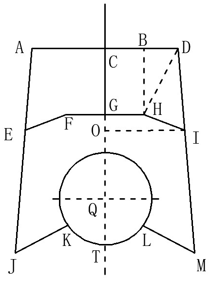
Among other components, a pipe-climbing robot is composed of a driving device, a suction device, and a clamping and rotating device. The driving device drives the robot to move. The suction device is composed of a permanent magnet and a yoke, and the permanent magnet is moved up and down by a screw in the suction device. The increase and decrease of the adsorption force are realized so that the robot can adhere to the pipe wall without falling. The clamping and rotating device is used as the auxiliary of the adsorption device to maintain the travelling direction and rotation of the robot. Figure 1 shows the specific structure of the robot.

Figure 1The two-dimensional model of the pipe-climbing robot. 1 – Carrier shelf, 2 – carrier, 3 – front frame, 4 – connecting rod, 5 – steering gear, 6 – steering gear, 7 – rear frame, 8 – drive wheel bracket, 9 – absorption screw, 10 – absorption sleeve, 11 – absorption permanent magnet, 12 – pushing screw, 13 – link block, 14 – connecting rod, 15 – cushion spring, 16 – drive wheel motor, 17 – rotating wheel motor, 18 – steering wheel, 19 – clamping arm, 20 – pipeline, 21 – pushing screw-stepper motor, 22 – absorption screw-stepper motor, and 23 – driving wheel.
The clamping arms on both sides are the key components of the clamping and rotating device, and their size is related to whether clamping and rotating actions can be carried out. Thus, the dimensional parameters of the clamping arms and connecting components were optimized in the present study.
2.1 Model establishment of the clamping and rotating device
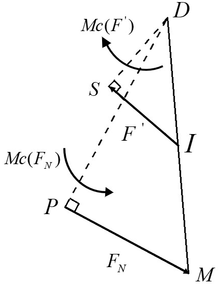
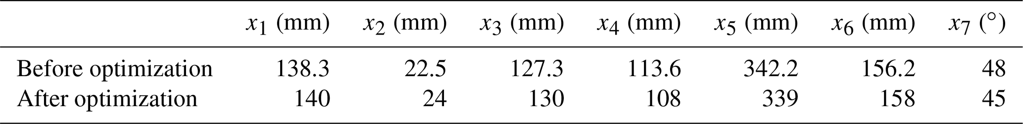
For the convenience of calculation, a simplified model was established. As shown in Fig. 1, because the clamping and rotating device is symmetrical, only the right side is analysed. G is the upper end of the connecting frame block and O is the downward movement of the connecting frame block. In Fig. 2, let CD, GH, HI, DI, DM, and LM respectively be x1, x2, x3, x4, x5, and x6, (mm), and let ∠DML be x7 (∘).
The design variables of the clamping and rotating device are as follows:
2.2 Mathematical model construction
2.2.1 Mechanical constraints
Figure 3 presents the force analysis of the clamping arm. The maximum distance that the connecting frame can move up and down under the drive of the screw rod was set as CG = 70 mm, the diameter of the pipe was set as 180 mm, and the distance from the centre of the pipe to the lower surface of the front frame was set as 220 mm. The force equation of the pipe-climbing robot during movement can be expressed as
where F is the rated tension of the screw rod, F′ is the pulling force at point I, α is ∠DIH, FN is the clamping force generated by the clamping point M of the clamping arm in the clamping state, Mc(F′) is the moment of pull-down force F′ on point D in the clamping state, and Mc(FN) is the moment generated by the clamping force FN generated at the clamping point M to point D in the clamping state.
2.2.2 Geometric dimensional constraints
During the movement of the robot, it must first be ensured that the installation space of each component is complete and does not interfere with other components; for the clamping and rotating device in particular, it must be ensured that the clamping arms on both sides do not collide with each other during the clamping action and that the robot can move normally on the outside of the pipe. Because collision with the pipe cannot occur, the geometric constraints are established as follows:
The following conditions must also be met in order to avoid motion interference. ∠BDI is β.
When the pipe is clamped by the clamping and rotating device, the angle between the two clamping arms should be 120∘; thus, ∠KQT should be between 55 and 65∘ and the formula is as follows. ∠IDH is χ, ∠JCL is δ, and ∠MDL is ε.
When the connecting frame block and the two connecting rods are in a straight line, the horizontal distance from the steering wheel to the centre point of the pipeline should be greater than 0.16 m, and the formula is as follows. ∠IDL is ϕ.
2.2.3 Objective function establishment
The objective function is established with the maximum clamping force of the clamping and rotating device on the pipe when the screw is in the clamping state. ∠HIO is φ.
To meet the optimization goal, each component should be as compact as possible; therefore,
Thus, the final objective function is as follows (mm):
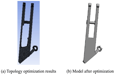
2.3 Optimization results
The use of the fminocon( ) function is optimized as follows:
The calling format of this function is as follows:
In the formula, F is the objective function, CF is the M file for the nonlinear constraint function, OPT is the control option, X is the design variable, and fopt is the optimization result of the objective function. The optimization results are reported in Table 1 and the optimized 3D models of the robot are respectively illustrated in Fig. 4.

By analysing the maximum deformation and equivalent stress distribution of the robot under different loads, the relevant performance of the robot was determined and then optimized. Different load applications of the robot were converted into the states of the related components under different working conditions (W. Wang et al., 2020). The movement of the robot can be divided into two working conditions, namely, the no-load and full-load conditions. The full-load condition has an impact on the performance of the robot components and the requirements are the greatest under this condition. When the robot is fully loaded, the displacement and deformation of the robot frame and the clamping arm are the greatest. Therefore, the key components of the robot were analysed under the full-load condition.
It was assumed that the working equipment carried by the robot was 5 kg, the suction force was 20 N when fully loaded, the rear suction force was 45 N when the front end was lifted, and the working equipment was fixed on the front frame. In Fig. 5, under the full-load condition, the robot is parallel to the pipeline and the front of the robot is lifted.
3.1 Static analysis
The simplified robot model was imported into ANSYS Workbench software. The material was set as aluminium alloy (6063-T5), the yield strength of which was 145 MPa, the elastic modulus of which was 69GPa, and the Poisson's ratio of which was 0.33 (Yan et al., 2020).
3.1.1 Parallel to the pipeline
When the robot is working on the pipeline, the detection device is mounted on the front frame; thus, the front frame and the part of the clamping arm connected to the front frame were statically analysed.
Front frame
The front frame receives the pressure of the upper-end weight, the adsorption force of the lower-end adsorption device, the support force of the lower drive wheel, and the support force of the clamping and rotating device on both sides.
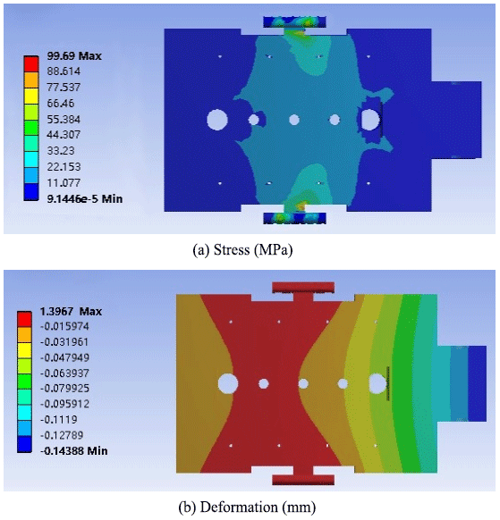
Figure 6 presents the cloud diagrams of the stress and deformation of the front frame, and it can be seen from Fig. 6a that the maximum stress of the front frame (99.69 MPa) occurred at the joint with the clamp arm hinge. Moreover, the maximum displacement was 1.4 mm. The maximum stress was less than the yield strength (145 Mpa), and the strength and stiffness of the structure were reasonable.
Front-frame clamping arm
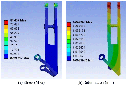
The front-frame clamping arm receives the pressure of the front frame and the upper part of the frame. When the robot is stationary, the clamping arm is in a clamped state and is subjected to the pulling force of the pushing screw, the adsorption force of the suction device, its own gravity, and the supporting force of the pipeline.
Figure 7 presents the cloud diagrams of the stress and deformation of the front-frame clamping arm, and it can be seen from Fig. 7a that the maximum stress of the front-frame clamping arm (84.407 MPa) occurred at the hinge connection between the clamping arm and the front frame. The maximum stress was less than the yield strength (145 MPa) and the maximum displacement was 0.069 mm.
3.1.2 Raised front frame
When the front frame is raised, the weight on the front frame falls on the rear frame and this analysis was also performed under full-load conditions.
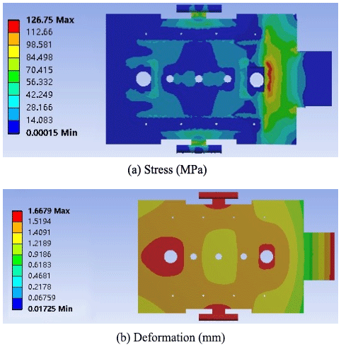
Rear frame
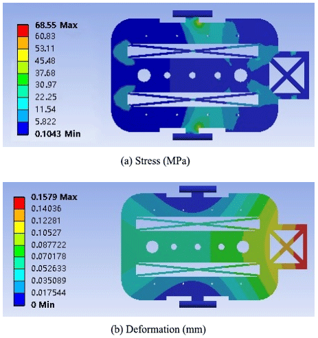
The upper end of the rear frame is under the pressure of the upper object and the lower end is supported by the clamping arms on both sides and its own gravity. The adsorption force was 45 N, and the stress and deformation cloud diagrams were obtained after applying the corresponding load and contact constraints.
The cloud diagrams of the stress and deformation of the rear frame are exhibited in Fig. 8. It can be seen from Fig. 8a that the maximum stress of the rear frame (136.75 MPa) occurred at the connection between the middle and the front frame. Figure 8b reveals that the maximum displacement was 1.7 mm. Moreover, the maximum stress was less than the yield strength which, therefore, meets the strength requirements.
Rear-frame clamping arm
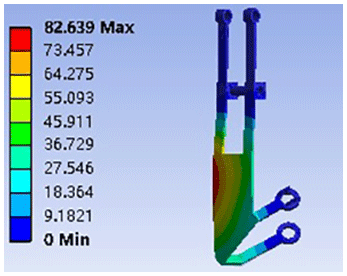
The rear-frame clamping arm receives the pressure of the rear frame and the part of the front frame mounted on the end of the rear frame. When the robot is stationary, the clamping arm is in a clamped state and is subjected to the pulling force of the pushing screw, the adsorption force of the suction device, its own gravity, and support from the pipeline.
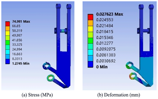
The cloud diagrams of the stress and deformation of the rear-frame clamping arm are exhibited in Fig. 9. It can be seen from the figure that the maximum stress of the rear-frame clamping arm (94.276 MPa) occurred at the hinge connection with the frame and the connection with the steering wheel, and meets the strength requirements. Furthermore, the maximum displacement was 1.65 mm.
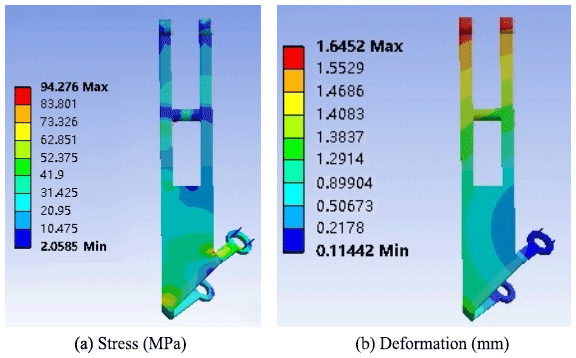
Figure 9The cloud diagrams of the stress and deformation of the clamping arm of the rear frame.
3.2 Modal analysis
The simplified robot model was imported into ANSYS Workbench software. The corresponding material properties were set, mesh division was performed, the constraint relationships were set, and modal analysis was performed on the frame and clamping arm.
3.2.1 Frame
Table 2 presents the sixth-order modal frequencies of the frame and Fig. 10 exhibits the first-order mode shape. It can be seen from the modal analysis that the lowest frequency of the frame was 44.224 and the overall dynamic characteristics were improved. The deformation of the intermediate shaft pin hole is large and the rigidity is small.

3.2.2 Clamping arm
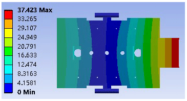
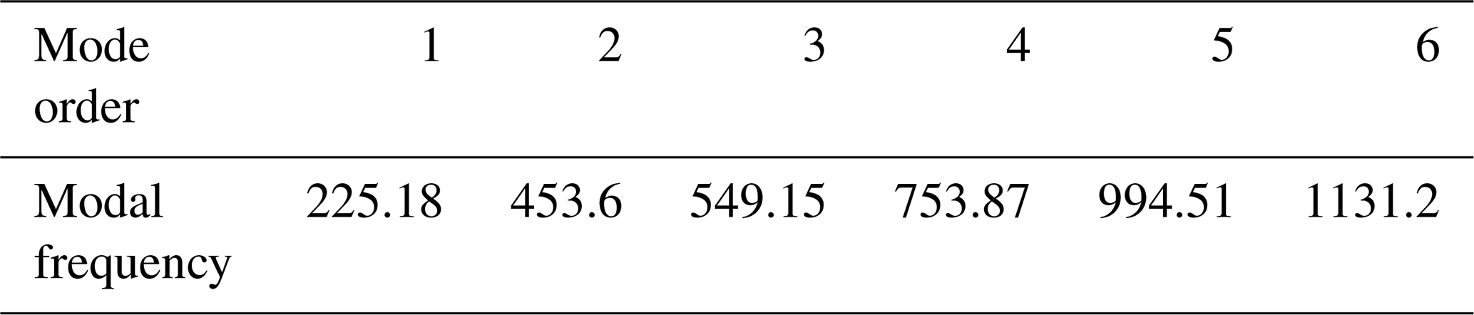
Table 3 reports the sixth-order modal frequencies of the rear-frame clamping arm and Fig. 11 presents the first-order mode shape. It can be seen from the modal analysis that the sixth-order modal frequencies of the clamping arm were between 225 and 1131 Hz. It can be seen from the figure that the deformation is larger in the lower half of the clamping arm, that is, between the connection with the connecting rod and the connection between the steering wheel mainly due to the excessive pressure when the frame is lifted. Greater deformation occurred between the connection of the connecting frame rod and the steering wheel which was primarily due to the lifting of the frame. So, optimize it by topology optimization.
Table 3The sixth-order modal frequencies of the clamping arm (Hz).
The variable density topology optimization method was applied in this research (Sookchanchai et al., 2021). Topology optimization is usually employed to determine the best material utilization or distribution in the design space under a given load. Therefore, structural optimization aims to achieve a local minimum, as given by Eq. (16).
In Eq. (16), the vector x represents the parameterization of the problem, f(x) is the objective function, and c(x) is the constraint condition of optimization. The objective function and constraints are the structural responses obtained from the finite-element analysis.
The material, contact, and other parameters of the structure were set in ANSYS Workbench software, the corresponding load was applied according to the motion mode of the robot, and the topology optimization module was applied for topology optimization. To meet the strength and rigidity requirements, the quality of the components was reduced as much as possible to make the structure more reasonable.
Compared with the state of being parallel to the pipe, the requirements for the frame when the front part is lifted are higher; thus, topology optimization was conducted for the frame and the clamping arm in the rear part under the lifted condition.
4.1 Frame optimization
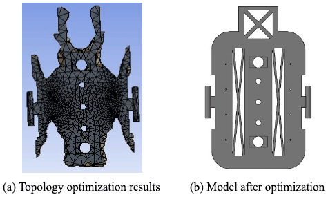
First, the frame was optimized according to the static analysis results; rounded corners were set, the maximum stress was improved, and topology optimization was performed. The topology optimization results are exhibited in Fig. 12.
4.2 Clamping arm optimization
In the two states under the full-load condition, the maximum stress of the clamping arm occurred at the connection of the hinge with the frame. Therefore, this was first improved and topology optimization was performed. The optimization results are exhibited in Fig. 13.
The analysis results of the rear frame were compared with those of the front lifted state and the rear-frame clamping arm.
5.1 Static analysis
The static analysis results of the frame and clamping arm are respectively presented in Figs. 14 and 15.
Compared with the results before optimization, the maximum stress of the front frame and the maximum stress of the clamping arm are obviously reduced to a certain extent.
5.2 Modal analysis
The sixth-order modal frequencies of the frame and clamping arm are respectively reported in Tables 4 and 5.

Table 5The sixth-order modal frequencies of the clamping arm (Hz).

In this work, a pipe-climbing robot was designed and its structure was optimized by MATLAB to make the structure more reasonable. Then, static and modal analyses were performed on the robot frame and clamping arm, and the frame was analysed under different working conditions. Moreover, the structural performance and the stiffness and stress distributions of the clamping arm were evaluated. Then, ANSYS Workbench software was employed to optimize the topologies of the frame and the clamping arm. By setting different parameters, the maximum deformation resistance that could be withstood relative to the defined load condition and the design space, the best structural material layout, and the most effective structure were determined.
After comparing the analysis results before and after optimization, it was found that the maximum stress of the frame was reduced by 46 %, the maximum displacement was reduced by 1.5 mm, and the mass was reduced by 24 % after optimization from the original 0.98 kg to the current 0.8 kg. Moreover, after optimization, the maximum stress of the clamping arm was reduced by 20 %, the maximum displacement was reduced by 1.6 mm, and the mass was reduced by 20 % from the original 0.36 kg to the current 0.3 kg. Ultimately, the rigidity and strength performances were enhanced, the quality was reduced, the structure was lightened, and the optimization goal was achieved. Thus, this work provides a reference for future research on pipe-climbing robots.
ANSYS finite-element analysis software was used to analyse the design of a climbing robot outside the tube. The code is not publicly available. For further information, please contact the corresponding author.
YZ provided the design ideas and thesis direction guidance. ML implemented the device design and related simulation design. BL, GM, JL, and MX provided the backup technical support.
The contact author has declared that none of the authors has any competing interests.
Publisher's note: Copernicus Publications remains neutral with regard to jurisdictional claims in published maps and institutional affiliations.
This work was supported by the Qingdao Postdoctoral Applied Research Project (grant no. A2020-070), the Natural Science Foundation of Shandong Province (grant no. ZR2020QE151), and the Qingdao Huanghai University Doctoral Research Fund Project (grant no. 2020boshi02).
This paper was edited by Giovanni Berselli and reviewed by three anonymous referees.
Bach, D., Makoto, O., and Makoto, Y.: Sequential mixture of Gaussian processes and saddlepoint approximation for reliability-based design optimization of structures, Struct. Multidiscip. O., 64, 02855, https://doi.org/10.1007/s00158-021-02855-w, 2021.
Chen, C., Chen, H., and Wu, S.: Structural Optimization of Industrial Robot Manipulator, Machine Tool & Hydraulics, 49, 25–29, 2021.
Ding, M., Geng, D., and Zhou, M.: Topology Optimization Strategy of Structual Strength Based on Variable Density Method, Journal of Shanghai Jiaotong University, 55, 764–773, https://doi.org/10.16183/j.cnki.jsjtu.2019.301, 2021.
Gao, Z.: Optimal Design of Mechanical Structure of Drive Shaft of Warehouse Rail Shuttle, Internal Combustion Engine & Parts, 10, 199–200, https://doi.org/10.3969/j.issn.1674-957X.2021.10.095, 2021.
Kambampati, S., Gray, J. S., and Alicia, K.: Level set topology optimization of load carrying battery packs, Int. J. Heat. Mass. Tran., 177, 121570, https://doi.org/10.1016/j.ijheatmasstransfer.2021.121570, 2021.
Kermorgant, O.: A magnetic climbing robot to perform autonomous welding in the shipbuilding industry, Robot. Cim.-Int. Manuf., 53, 178–186, https://doi.org/10.1016/j.rcim.2018.04.008, 2018.
Liu, Q., Fan, G., Tan, Z., and Zhang, H.: Precipitation of Al3Zr by two-step homogenization and its effect on the recrystallization and mechanical prope-rty in 2195 Al–Cu–Li alloys, Mat. Sci. Eng. R., 821, 141637, https://doi.org/10.1016/j.msea.2021.141637, 2021.
Ma, X., Chen, W., and Ren, Y.: Structural optimization design for the laser support structure based on ANSYS Workbench, Manufacturing Technology & Machine Tool, 1, 30–33, https://doi.org/10.19287/j.cnki.1005-2402.2020.01.002, 2020.
Shen, H., Bian, F., Yue, Y., Li, B. C., Yu, P., Yang, L. H., Chen, G. S., and Hu, L.: Multi-Structural Optimization of Bearingless Permanent Magnet Slice Motor Based on Virtual Prototype in Ansoft Maxwell, Appl. Sci., 11, 4740, https://doi.org/10.3390/app11114740, 2021.
Salehpour, M. H., Taghirad, H. D., and Moradi, H.: Two PID-Based Controllers for atethered Segway on Dome Shaped Structures, 2018 6th RSI International Conference on Robotics and Mechatronics, 2018.
Soliman, M., Frangopol, D. M., and Mondoro, A.: A probabilistic approach for optimizing inspection, monitoring, and maintenance actions against fatigue of critical ship details, Struct. Saf., 60, 91–101, https://doi.org/10.1016/j.strusafe.2015.12.004, 2016.
Sookchanchai, K., Olarnrithinun, S., and Uthaisangsuk, V.: Lightweight design of an automotive lower control arm using topology optimization for forming process, IOP Conf. Ser.-Mat. Sci., 1157, 012183, https://doi.org/10.1088/1757-899X/1157/1/012083, 2021.
Wang, L., He, F., and Han, Y.: Simulation study of plastic tailgate torsion stiffness based on finite element analysis, Manufacturing Automation, 42, 129–132, 2020.
Wang, W., Yang, Q., and Sun, C.: Motion coordinated simulation and experimental study of dual-robot system, Modular Machine Tool & Automatic Manufacturing Technique, 4, 42–46, 2020.
Xue, R., Du, Z., and Guo, X.: Topology optimization of hyperelastic struct ures via Moving Morphable Void (MMV) approach, Chinese Journal of Computational Mechanics, 36, 441–447, https://doi.org/10.7511/jslx20180702001, 2019.
Yan, G., Shen, X., and Yu, F.: Optimization design of frame struc ture of ROV based on ANSYS-workbench, Manufacturing Automation, 42, 1–3+7, 2020.
Zhang, J., Chen, Y., Zhai, J., Hou, Z., Han, Q.: Topological optimization design on constrained layer damping treatment for vibration suppression of aircraft panelvia improved Evolutionary StructuralOptimization, Aerosp. Sci. Technol., 112, 106619, https://doi.org/10.1016/j.ast.2021.106619, 2021.