the Creative Commons Attribution 4.0 License.
the Creative Commons Attribution 4.0 License.
 | 20 Jul 2022
Structural analysis of ancient Chinese textile mechanisms
Shi-Wu Li
Ming-Jie Wang
Yan-An Yao
China is one of the first countries that produced textiles in the world. It has designed and developed a variety of equipment to facilitate textile work, for instance, reeling wheels for fiber processing, treadle spinning wheels for spinning, and looms for weaving cloth. These textile mechanisms can be found in the literature, and there are physical objects left as well. However, due to unclear descriptions of the transmission modes in the records and illustrations, as well as the long history and vast area of their use, a variety of designs with different structures may have been produced. Based on the generalized kinematic chain concept, this paper briefly describes the historical development of textile mechanisms in ancient China and analyzes the structures of mechanisms, such as reeling wheels, treadle spinning wheels, and looms. Finally, it explores the degree of freedom of the mechanisms to find feasible designs in line with functional requirements.
- Article
(6030 KB) - Full-text XML
- BibTeX
- EndNote


The ancient China textile industry had a long history of development with many important mechanical creations. It is a miniature of the development of ancient Chinese civilization. Industrial textile mainly consists of four steps: fiber processing, spinning, dyeing and finishing, and weaving. Fiber processing involves processing the silkworm cocoon, cotton, or hemp by reeling off raw silk (seeding) or rubbing and twisting strands to prepare them for spinning. After fiber processing, spinning converts the raw materials into yarns or produces the folded yarn by joining and twisting multiple single yarns. Then, the yarn is treated with warp and weft yarn fiber processing as preparation for weaving. Dyeing and finishing of the textile is achieved by chemical or physical methods that can dye the yarn while increasing its strength. Weaving interweaves the warp and weft yarn – processed with dyeing and finishing – in a perpendicular blending manner through the weaving device to make cloth.
There is extensive ancient Chinese technical literature containing mechanism illustrations, such as The Book of Agriculture by Wang (1969) of the Yuan Dynasty, Tiangong Kaiwu by Song et al. (1966) of the Ming Dynasty, and the Comprehensive Treatise on Agricultural Administration by Xu (1968) of the Ming Dynasty. This literature uses texts and pictures to introduce the textile equipment at the different times, and it has a research and reference value. However, due to incomplete or erroneous drawings, the types of the members and joints cannot be determined at times, making it impossible to clearly understand the actual operational situations of the mechanism. Hommel (1937) conducted a long field investigation, introduced several pieces of common textile equipment in ancient China, and briefly compared them with the textile machinery of ancient Europe. Needham (1965) briefly described the types of textile machinery in China and the West and the exchange and intercommunication between them. He also introduced the structures of several representative textile machineries. Lu (2003) described the actual production and application of textile equipment in various dynasties from the perspective of ancient Chinese machinery development. Zhang et al. (2004) briefly introduced simple ancient textile tools and revealed the process of how they developed into the mature looming and weaving technologies and discussed the evolution process of the textile machinery. Yan and Hsiao proposed a method that can systematically deduce a restoration design in line with historical data and modern technological levels based on the theory of mechanisms and the machine concept design method (Yan, 2016, 1998; Hsiao and Yan, 2014). However, they did not discuss the issues concerning the degree of freedom of textile mechanisms. Therefore, this paper briefly describes the historical development of textiles in ancient China, analyzes the structures of textile equipment, such as reeling wheels, treadle spinning wheels, and looms based on the generalized kinematic chain concept, and explores the degree of freedom of the mechanisms to present some possible designs.
The production of textiles in China dates back to several thousand years ago. As early as in primitive society, people had already started to collect wild hemp and natural silk and utilizing the hair and feathers of hunted animals. They wove simple clothes to replace grass and animal skins to cover themselves. In the latter period of primitive society, with the development of agriculture and livestock farming, people gradually grasped the artificial production of textile raw materials, such as extracting fiber from hemp, keeping sheep to get wool, and breeding silkworms for silk. In addition, they also began to use more tools, which greatly increased their productivity. From then on, decorative patterns and colors started to appear on textiles. However, all the tools – for example, the spinning wheel and spindle stick used for spinning – were driven directly by human hands; hence, this technique is called primitive hand spinning and weaving.
Approximately 3000 years ago, textile production made a great leap in both quantity and quality. After a long time of development, the textile tools had evolved into primitive manual textile machineries, such as cotton gin for fiber processing and a hand spinning wheel for spinning, as shown in Fig. 1. Furthermore, textile producers gradually became specialized, consequently promoting the development of textile technology. Textiles became the objects of transactions, and in some cases they even played the role of currency as a medium for exchange. By the Spring and Autumn period and the Warring States period (770–221 BCE), silk fabrics were already exquisite. With various textures and rich colors, silk textile became a noble clothing fabric well-known far and wide. Below the stages from the beginnings to the formation of manual mechanized spinning and weaving are outlined.
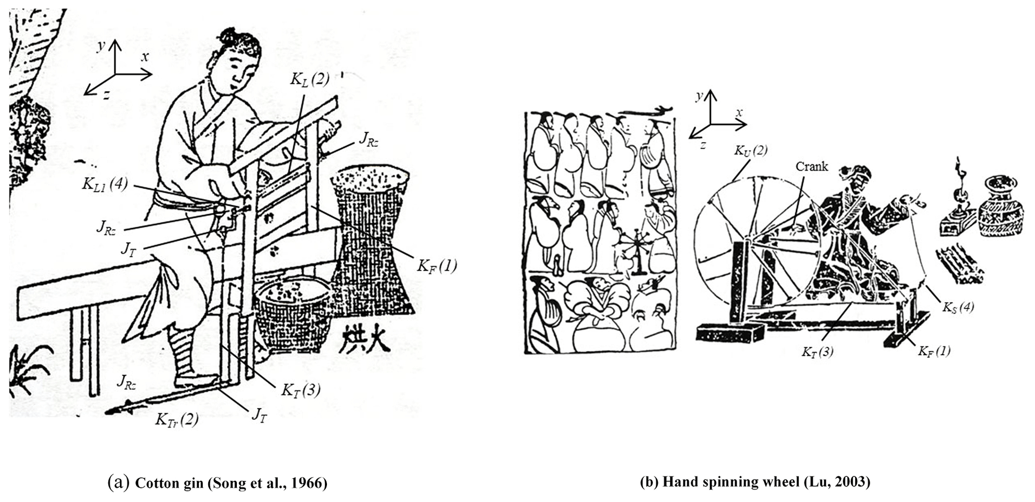
Figure 1Cotton gin and hand spinning wheel.
From the Qin and the Han dynasties (221 BCE–220 CE) to the Qing Dynasty (1636–1912 CE), natural silk was famous in the world as a specialty of China. During this period, the structure of manual textile machinery had become more complex to make looming and weaving more efficient and to produce better-quality textile. For example, the spinning wheels developed from single-spindle hand spinning wheels into multi-spindle (three to five spindles for each set) treadle spinning wheels, and the looms had developed into two major types, the plain and patterned looms. The textiles also had a variety of patterns and colors. The major fabric weaves known today, such as plain, twill, and satin weaves, were all widely used in the Song Dynasty (960–1279 CE). Silk fabric remained a high-end product as a clothing material, and arts and crafts silk textiles also appeared mainly for appreciation. During the Yuan and the Ming dynasties (1206–1636 CE), cotton spinning and weaving technology developed rapidly, and materials for daily clothing gradually changed from hemp to cotton cloth – the development period of manual mechanized spinning and weaving.
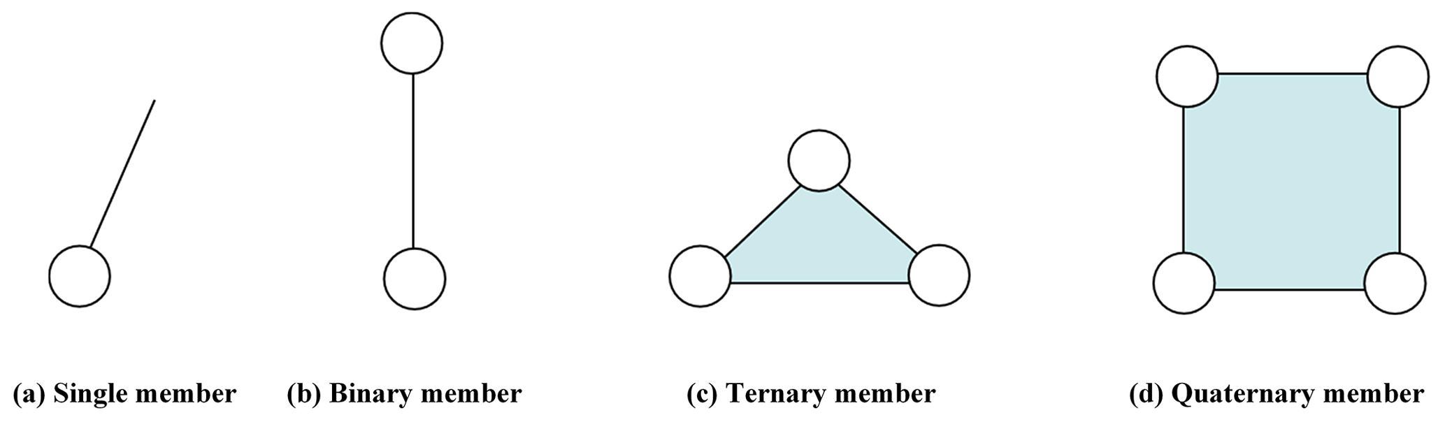
Textile machinery comprises members and joints in specific ways to realize the desired movement functions. In analyzing the structure of textile machinery, the generalized chain can be used to represent the movement relations between members and joints (Shi et al., 2020, 2017; Dong et al., 2020). According to the number of joints they are connected to, members can be categorized as a single member, binary member, ternary member, and quaternary member, and joints are represented with circles, as shown in Fig. 2 (Yan and Kuo, 2006; Hsiao, 2017, 2018).
The cotton gin, shown in Fig. 1a, is used for cotton fiber processing before looming and weaving. The treadle is stepped on to produce reciprocating motions, rotating the roller via the rope. Meanwhile, one hand rotates another roller; hence, the two rollers rotate in opposite directions. Using the empty hand to add cotton between the rollers, one can squeeze the cotton core and cotton seed at a higher efficiency. Stepping on the treadle to drive the roller via a rope requires a flywheel, which can force the roller to rotate with inertia force (the flywheel is not illustrated in the figure).
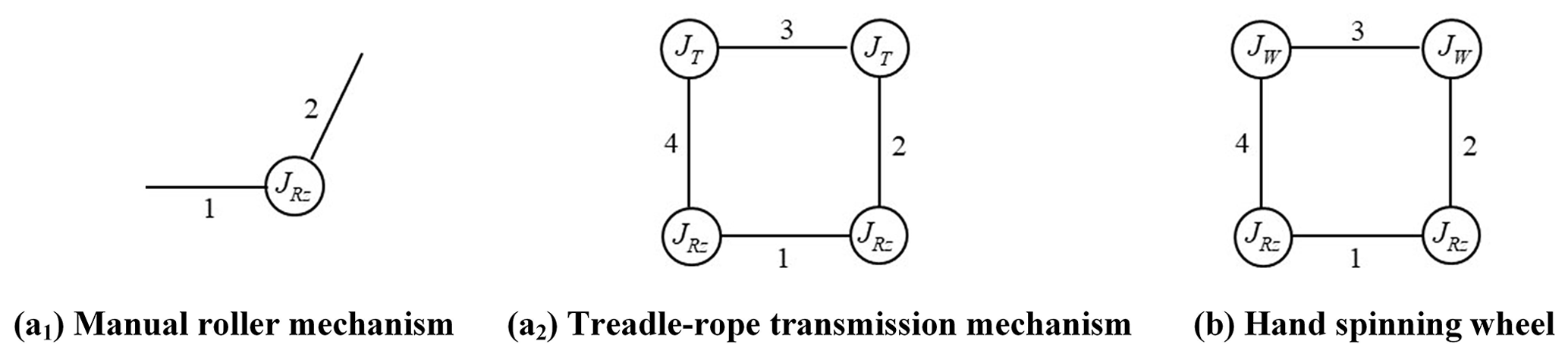
The cotton gin can be divided into two mechanisms: the manual roller and the treadle-rope transmission. The manual roller mechanism has two members and one joint. With a wooden frame as the frame (member 1, KF) and a roller as the motion link (member 2, KL), the roller connects to the frame with revolute joint . The corresponding chain is shown in Fig. 3a.1. The treadle-rope transmission has four members and four joints. It includes a wooden frame as the frame (member 1, KF), a treadle (member 2, KTr), a rope (member 3, KT), and another roller (member 4, ). The treadle connects to the frame via revolute joint , the rope connects with the treadle and the roller via thread joint JT, and the roller connects with the frame via revolute joint . The corresponding chain is shown in Fig. 3a.2.
Figure 1b shows a single-spindle hand spinning wheel found on a wall painting of a Han Dynasty tomb. It includes the frame (member 1, KF), the wheel with crank (member 2, KU), the rope (member 3, KT), and the spindle (member 4, KS). The wheel, which is rotated by the crank, drives the rope and the spindle at high speed for spinning thread. The wheel connects to the frame via revolute joint , the rope connects with the wheel and the spindle via wrapping joints JW, and the spindle connects with the frame via revolute joint . The corresponding chain is shown in Fig. 3b.
Various textile mechanisms were invented and used in ancient China. They utilized a variety of different mechanical members, such as link, pulley, and flexible parts, and generated manifold motion characteristics through the motion transmission between these members. Though these mechanisms have been documented and physical objects have been recovered, there are still multiple possible designs for their mechanical structures. Therefore, we describe the purpose and components of the reeling wheel, the treadle spinning wheel, and the loom, analyze their structures, and discuss their feasible designs.
4.1 The reeling wheel
The reeling wheel is used to extract and reel natural silk fibers. The earliest records of a reeling wheel appeared in the Tang Dynasty (618–907 CE). Early reeling wheels were operated with two hands and required two people to work together to get silks out. By the Song Dynasty (960–1279 CE) at the latest, reeling wheels operated by feet appeared and only one person could use their hands and feet to complete the work (Zhang et al., 2004). Figure 4 shows the original illustration in The Book of Agriculture (Wang, 1969), the structure of which consists of the frame (member 1, KF), the treadle (member 2, KTr), the connecting link (member 3, KL), the roller with crank (member 4, KCR), the rope (member 5, KT), the pulley with crank (member 6, KWC), and the silk-guiding link (member 7, KGL). Natural silk is extracted from silkworm cocoons in the cocoon boiler; it passes through the bore of the copper coin across the wooden shelf and through the groove on the silk-guiding link and is finally wound on the roller. The pulley with a crank on the table has a groove. The rope is wound on the groove of the pulley and the roller. And the crank is connected to the silk-guiding link. When driven by stepping on the treadle with one's foot, the connecting link drives the roller to rotate and transmits power to the rope, the pulley, and the silk-guiding link, making the silk-guiding link move back and forth. As the silk thread passes through the groove on the silk-guiding link before being wound on the roller, the reciprocating motion of the silk-guiding link can arrange the silk thread collected on the roller in proper order and evenly distribute it within a range (Hsiao et al., 2010). According to different functions, a reeling wheel can be divided into two sub-mechanisms, namely the treadle connecting link mechanism and the silk thread guiding mechanism, described in the following.
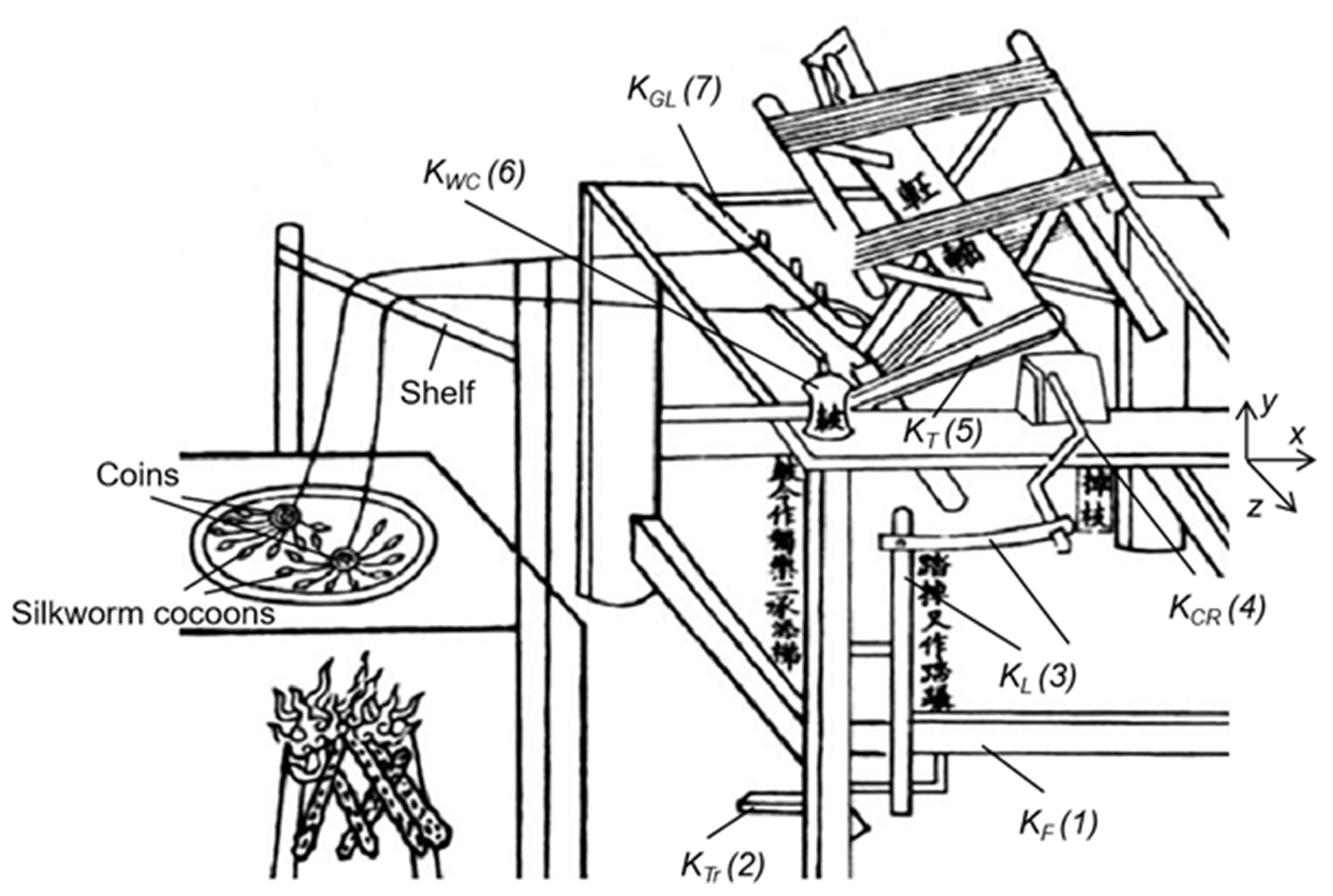
Figure 4Reeling wheel (Wang, 1969).
4.1.1 The treadle connecting member mechanism
The treadle connecting link mechanism consists of at least the frame (member 1, KF), the treadle (member 2, KTr), the connecting link (member 3, KL), and the roller with crank (member 4, KCR). The reciprocating swing motion of the treadle is converted into the rotary motion of the roller. As shown in Fig. 4, a set of the Cartesian coordinate system is defined, with the z axis being the axial direction of the roller and the x axis and the y axis being defined as the horizontal and vertical directions of the table, respectively. In this sub-mechanism, the treadle (KTr) is a binary member, which connects with the frame (KF) and the connecting link (KL) via revolute joints (), and the roller connects with the frame (KF) and the connecting link (KL) via revolute joints ().
4.1.2 The silk thread guiding mechanism
The silk thread guiding mechanism consists of the frame (member 1, KF), the roller with crank (member 4, KCR), the rope (member 5, KT), the pulley with crank (member 6, KWC), and the silk-guiding link (member 7, KGL). The rotation of the roller drives the pulley with a crank via the rope, and the rotation of the pulley drives the silk-guiding link to move back and forth so as to arrange the silk thread on the roller in good order. In this sub-mechanism, the rope (KT) is a binary member, and it connects with the roller (KCR) and the pulley (KWC) via wrapping joints (JW). The pulley with a crank (KWC) is a ternary member, and it connects with the frame (KF) and the silk-guiding link (KGL) via a revolute joint () and an uncertain joint (J1). The silk-guiding link is a binary member, and it connects with the frame (KF) via an uncertain joint (J2).
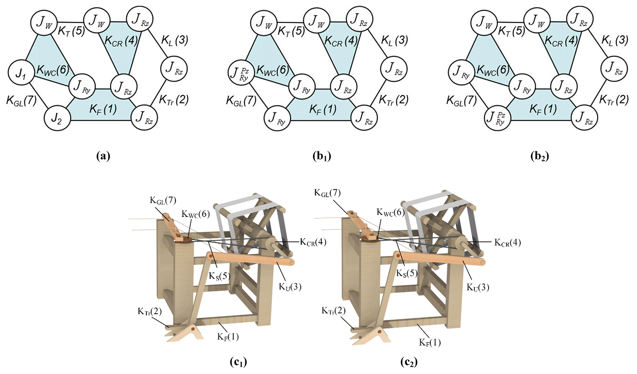
According to the analysis above, both the treadle connecting link mechanism and the silk thread guiding mechanism are planar mechanisms that can realize the required function. The corresponding chain of the reeling wheel is shown in Fig. 5a. According to the Grübler–Kutzbach criteria, which determine the degree of freedom of a planar mechanism (Yan, 2016), and considering the uncertain joints J1 and J2 of the three-member circuit formed by the frame (KF), the pulley with crank (KWC), and the silk-guiding link (KGL), the degrees of constraint for these two joints are discussed as follows.
-
As the number of isolated entries for this mechanism is 1 and no special concern is involved, the degree of freedom of the mechanism is 1.
-
The expression for the degree of freedom of a planar mechanism is shown in Eq. (1):
where NL is the number of members in the mechanism; is the number of Type i joints, and is the degree of constraint of joint Ji.
-
The number of members in this three-member circuit, NL, is three. Also, there is a revolute joint, and its degree of constraint in a planar mechanism is 2. According to Eq. (1),
-
According to Eq. (2),
Therefore, suppose an uncertain joint J1 is a revolute joint (). The uncertain joint J2 shall be a joint with 2 degrees of freedom – for instance, the pin-in-slot joint expressed as . These two uncertain joints can be exchanged. The chains corresponding to feasible designs are shown in Fig. 5b.1–b.2, and the simulation drawings are shown in Fig. 5c.1–c.2.
4.2 The treadle spinning wheel
In the Han Dynasty (206 BCE–220 CE), spinning wheels were operated by hands and were widely used (Zhang et al., 2004). However, the spinner turned the wheel with one hand and pulled the yarn with the other hand, which often resulted in uneven yarn thickness. The treadle spinning wheel uses the operator's feet as the power source. The feet rather than the hands control the treadle to drive the great wheel. With both hands, spinning can be more efficient, and the quality of the yarn is enhanced, as shown in Fig. 6 (Song et al., 1966; Hommel, 1937). It combines one or several threads of natural silk, cotton thread, or hemp fiber into a new thread through rubbing and twisting and collects the yarn roll for the spinning spindle on the spindle. Figure 6a shows that a spinner steps on the treadle to drive the great wheel in order to drive the two spindles to rotate simultaneously via the rope on the great wheel, making four single yarns into a two-fold yarn wound on the spindle through twisting. Its basic structure consists of the frame (member 1, KF), the treadle (member 2, KTr), the great wheel (member 3, KU), the rope (member 4, KT), and the spindle (member 5, KS).
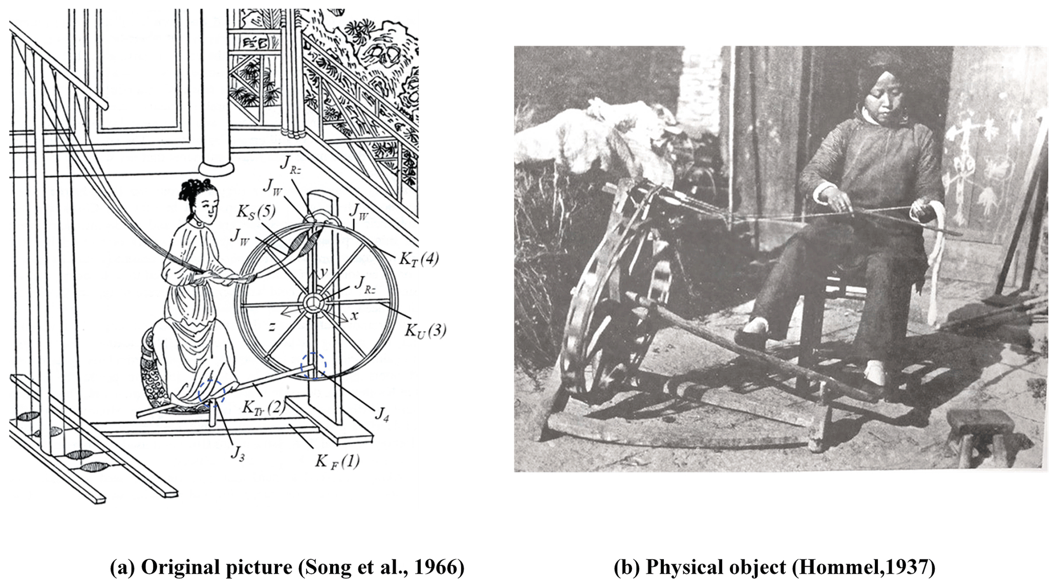
Figure 6Treadle spinning wheel.
In this mechanism, the treadle (KTr) is a binary member and connects with the frame (KF) and the great wheel (KU) via uncertain joints J3 and J4. The great wheel (KU) is a ternary member and connects with the frame (KF) and the rope (KT) via a revolute joint () and a wrapping joint (JW). The spindle (KS) is a binary member and connects with the frame (KF) and the rope (KT) via a revolute joint () and a wrapping joint (JW). The corresponding chain is shown in Fig. 7a.
According to the above analysis, the operator needs to control the treadle with two feet to drive the great wheel to rotate. Therefore, the treadle spinning wheel must be a spatial mechanism to meet the functional requirements. According to the Grübler–Kutzbach criteria, which determine the degree of freedom of a spatial mechanism, and considering the uncertain joints J3 and J4 in the three-member circuit of the frame (KF), the treadle (KTr), and the great wheel (KU), the degrees of constraint of these two joints are as follows.
-
As this mechanism uses two feet to control the treadle, the degree of freedom of the mechanism can be 1 or 2.
-
The expression for the degree of freedom of spatial mechanism is shown in Eq. (4):
where NL is the number of mechanism members, is the number of Type i joints, and is the degree of constraint of joint Ji.
-
The number of members, NL, in this three-member circuit is three, and there is one revolute joint. When the degree of freedom of a joint in a spatial mechanism is 1, the degree of constraint is 5. According to Eq. (4), it can be obtained as follows:
-
According to Eq. (5), it can be obtained as follows:
In order to enable the treadle to drive the great wheel for continuous rotation, the uncertain joints J3 and J4 need to have a continuous rotation degree of freedom in one axial direction and must have a restricted swinging rotation degree of freedom in another axial direction. Therefore, the degree of freedom of the joints is at least 2, and these two joints are exchangeable. According to modern spatial joint theory and the easy-to-make perspective, the possible types of joints are pin joints and spherical joints. The motion methods of a pin joint in the spatial mechanism can be the two-axial rotation and two-axial prismatic, and their degree of constraint is 2, which can be expressed as or . The motion methods of a spherical joint in the spatial mechanism can be a three-axial rotation, and their degree of constraint is 3, which can be expressed as . Therefore, the possible joint types of uncertain joint J3 are and , and the possible joint types of uncertain joint J4 are and . According to the restrictions by the degree of constraint, the chains of a feasible design are shown in Fig. 7b, and the simulation drawings are shown in Fig. 7c.
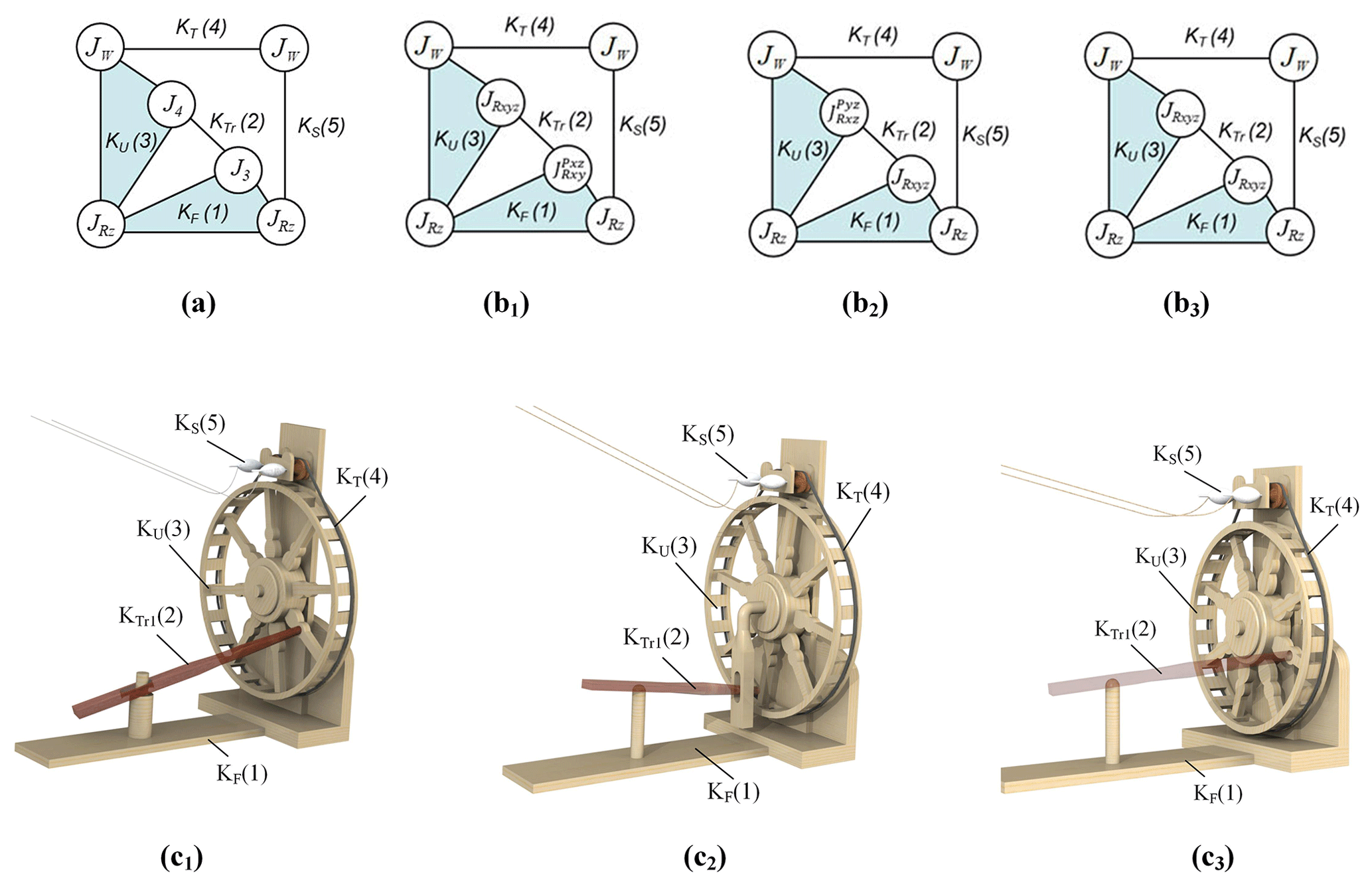
Figure 7Chains and simulation drawings of treadle spinning wheel (Hsiao and Yan, 2014).
4.3 The loom
According to unearthed textile relics, primitive looms appeared at the latest 5000 years ago. The structure of the primitive loom is simple and has no frame. The weaver uses the waist and legs to control the plane of the warp and complete the work of weaving. The primitive loom was still in use until 100 CE in ancient China. Around 1000 BCE, the frame, the heddles, and the heddle rods were added to the loom, giving it the complete weaving function (Zhang et al., 2004). The loom drives the transmission rope and the connecting link via the treadle, opening the shuttle path and facilitating the weaving process. It is a typical design of ancient Chinese weaving mechanisms, as shown in Fig. 8 (Song et al., 1966; Hommel, 1937). The weaving processes include the four steps, namely opening the shuttle path, weft insertion, weft pressing, and cloth rolling. It also includes three sub-mechanisms, namely the treadle heddle-lifting mechanism, the weft-pressing mechanism, and the cloth-rolling mechanism, required to produce plain-weave cloth (Hsiao and Yan, 2014). Figure 8c shows the structure of a dual-treadle, dual-heddle loom. One end of the warp is wound on the warp beam, and the other goes through the eye hole of the heddle. The heddle consists of an upper heddle rod, a lower heddle rod, and the eye holes of the heddle. The weaver steps on the treadle to drive the thread and the scale link. Consequently, the heddle moves up or down through the treadle heddle-lifting mechanism. When the heddle lifts or drops, it also raises or drops the warp, and the shuttle path is then provided. The weft is placed inside the shuttle, and for easier shuttle-picking through the shuttle path opening, both ends of the shuttle are pointy, as shown in Fig. 8d. When the shuttle is picked, the weft falls on the warp. After every shuttle picking, a weft-pressing rod of the weft-pressing mechanism must be used to firmly press the weft, making it part of the woven cloth. As the weaving process goes on, the newly woven cloth is wound on the cloth beam, and the warp needs to be released from the warp beam simultaneously.
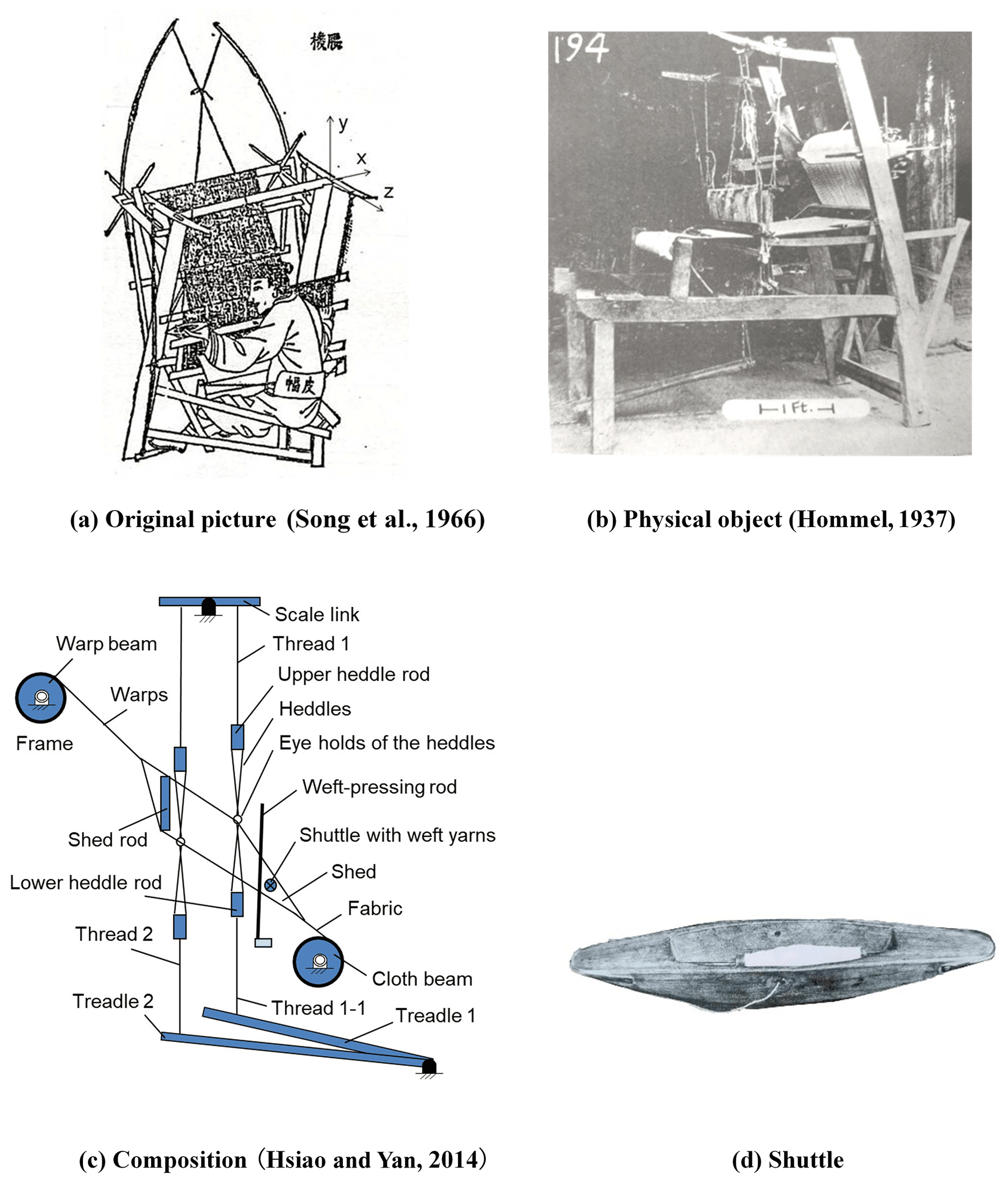
Figure 8The loom.
According to their functions and applications, the loom can be divided into three sub-mechanisms, namely the treadle heddle-lifting mechanism, the weft-pressing mechanism, and the cloth-rolling mechanism, described in the following.
4.3.1 The silk thread guiding mechanism
The quality of weaving is directly related to the opening and closing of the shuttle path, and the treadle heddle-lifting mechanism is a major component of controlling the shuttle path. It consists of six members: the frame, two treadles, two threads, and a scale link. In this mechanism, Treadle 1 (member 2, ) is a binary member and connects with the frame (KF) via the revolute joint (). Thread 1 (member 3, ) is a binary member and connects with treadle 1 () and the scale link (KSL) via thread joints (JT). The scale link (member 4, KSL) is a ternary member and connects with the frame (KF) via the revolute joint (). Thread 2 (member 5, ) is a binary member and connects with the scale link (KSL) and treadle 2 () via thread joints (JT). Treadle 2 (member 6, ) is a binary member and connects with the frame (KF) via the revolute joint (). The corresponding chain and the simulation drawing are shown in Fig. 9.
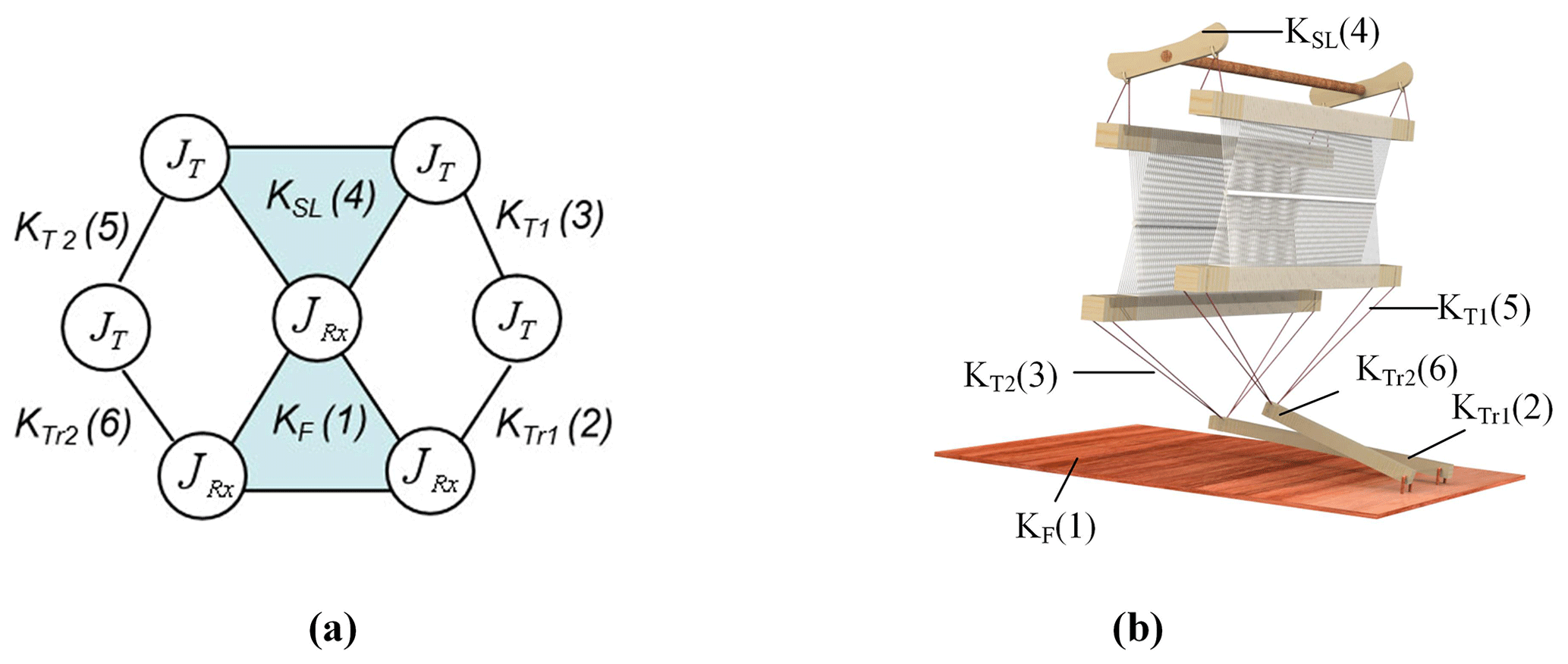
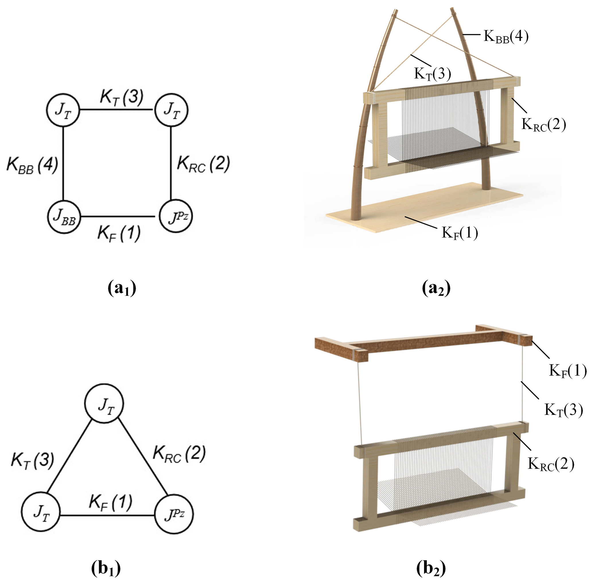
4.3.2 Weft-pressing mechanism
In order to make a compact structure of the textile, a weft-pressing rod must be used after each shuttle process to press the weft firmly. The mechanism, shown in Fig. 8a, uses bamboo as the flexible element to return the weft-pressing rod to its original place. Such a weft-pressing mechanism is a four-member mechanism and consists of the frame (member 1, KF), a weft-pressing rod (member 2, KRC), a rope (member 3, KT), and bamboo (member 4, KBB) that provides elastic force; among them, the weft-pressing rod is a binary member and connects with the warp and the rope via a prismatic joint () and a thread joint (JT). The warp is static at the moment and can be regarded as a frame. The bamboo is a binary member and connects with the frame and the rope via a bamboo joint (JBB) and a thread joint (JT), respectively. Figure 10a shows the corresponding chain and simulation drawing. Figure 8b shows a three-member weft-pressing mechanism consisting of the frame (member 1, KF), a weft-pressing rod (member 2, KRC), and a rope (member 3, KT). The rope connects with the frame and the weft-pressing rod via thread joints (JT), and the weft-pressing rod connects with the warp via a prismatic joint (). As the warp is static, it can be considered the frame. The corresponding chain and the simulation drawing are shown in Fig. 10b.
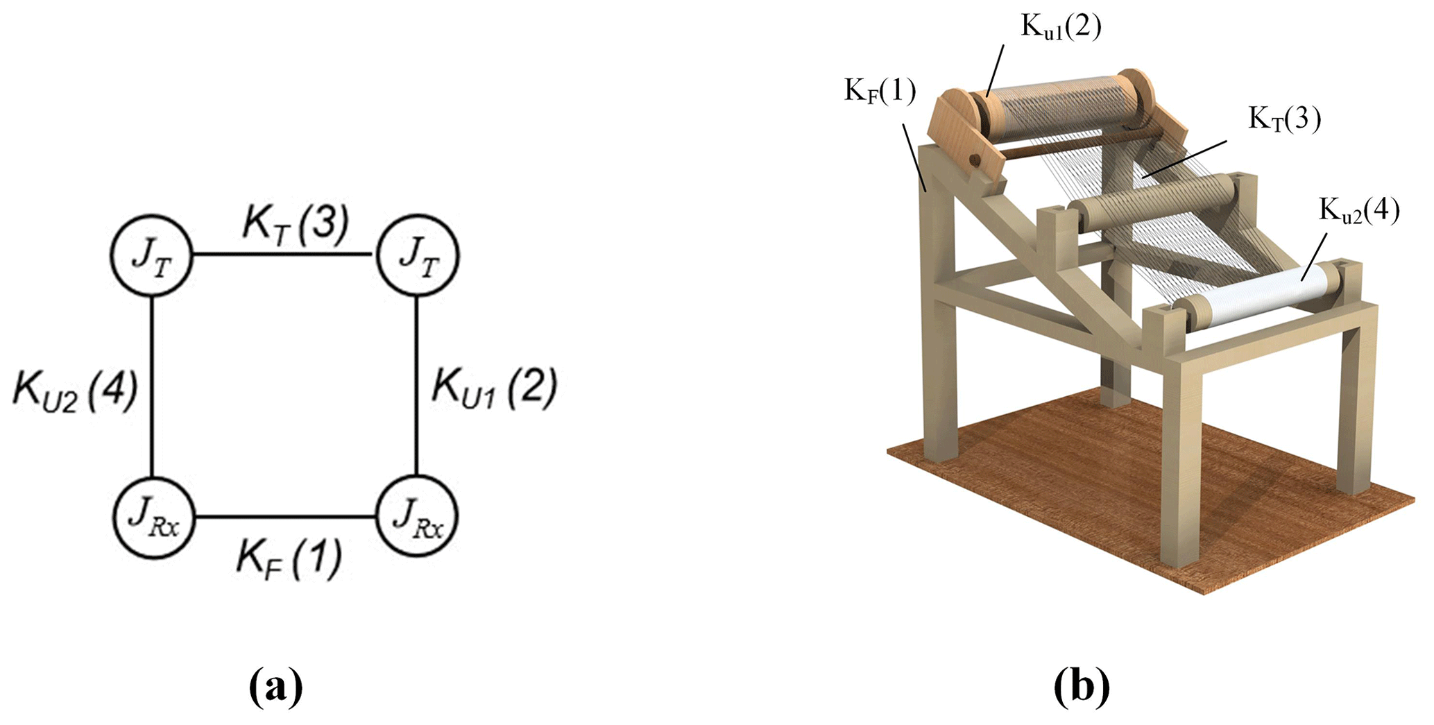
4.3.3 The cloth-rolling mechanism
In order to keep the tension of the warp on the loom and collect the cloth after the weft and the warp blends, the cloth-rolling mechanism is adopted. It consists of the frame (member 1, KF), a warp beam (member 2, ), the warp (member 3, KT), and a cloth beam (member 4, ). As for the joints, the warp beam connects with the frame via revolute joint , the warp connects with the warp beam and the cloth beam via wrapping joints JW, and the cloth beam connects with the frame via revolute joint . The corresponding chain and the simulation drawing are shown in Fig. 11.
The complex textile mechanisms of ancient China consist of connecting links, pulleys, and flexible transmission parts. A variety of motion characteristics is achieved through the interactions between the parts for textile works, including fiber processing, spinning, and weaving. In this paper, the concept of the generalized chain is used to perform structural analyses on three complex textile mechanisms, including the reeling wheel, the treadle spinning wheel, and the loom. The innovation of this paper and the difference to related studies is that this paper applied the criterion for the degrees of freedom to raise feasible design configurations for each textile mechanism. It provides a sketch for people to comprehend the characteristics of ancient Chinese textile mechanisms. As an effective tool, this method can reasonably deduce mechanical structure designs in accordance with motion characteristics and functional requirements. From the perspective of modern mechanical science, this method of the topological matrix not only clearly shows the structural changes in the textile mechanisms, but it is also an important aspect in the restoration of other ancient machinery.
The data are available upon request from the corresponding author.
SWL and KS directed the structural analysis of the textile mechanisms. MJW structured the paper. YAY made contributions to presentation approaches for the textile mechanisms.
The contact author has declared that none of the authors has any competing interests.
Publisher’s note: Copernicus Publications remains neutral with regard to jurisdictional claims in published maps and institutional affiliations.
The authors are grateful to the Shandong University of Science and Technology under grant 0104060540416 for the financial support of this work.
This research has been supported by the Elite Program of Shandong University of Science and Technology (grant no. 0104060540416).
This paper was edited by Guimin Chen and reviewed by two anonymous referees.
Dong, J., Shi, K., Zhang, Y., Tenigeer, and Yao, Y.: Mechanism analysis of ancient Chinese crossbows, Mech. Sci., 11, 437–445, https://doi.org/10.5194/ms-11-437-2020, 2020.
Hommel, R. P.: China at work: an illustrated record of the primitive industries of China's masses, whose life is toil, and thus an account of Chinese civilization, John Day Company, New York, 1937.
Hsiao, K. H.: On the structural analysis of open-keyhole puzzle locks in ancient China, Mech. Mach. Theory., 118, 168–179, https://doi.org/10.1016/j.mechmachtheory.2017.08.003, 2017.
Hsiao, K.-H.: Structural analysis of traditional Chinese hidden-keyhole padlocks, Mech. Sci., 9, 189–199, https://doi.org/10.5194/ms-9-189-2018, 2018.
Hsiao, K. H. and Yan, H. S.: Mechanisms in Ancient Chinese Books with Illustrations, 1st Edn., Springer International Publishing, https://doi.org/10.1007/978-3-319-02009-9, 2014.
Hsiao, K. H., Chen, Y. H., and Yan, H. S.: Structural Synthesis of Ancient Chinese Foot-operated Silk-reeling Mechanism, Front. Mech. Eng., 5, 279–288, https://doi.org/10.1007/s11465-010-0101-2, 2010.
Lu, J. Y.: History of Chinese Machinery, 1st Edn., Ancient Chinese Machinery Cultural Foundation, 2003.
Needham, J.: Science and civilization in China, Vol. 4, Part II, Cambridge University Press, Cambridge, 1965.
Shi, K., Zhang, Y., Lin, J. L., and Hsiao, K. H.: Ancient Chinese maze locks, T. Can. Soc. Mech. Eng., 41, 433–441, https://doi.org/10.1139/tcsme-2017-0030, 2017.
Shi, K., Hsiao, K. H., Zhao, Y., Huang, C. F., and Xiong, W. Y.: Structural analysis of ancient Chinese wooden locks, Mech. Mach. Theory., 146, 103741, https://doi.org/10.1016/j.mechmachtheory.2019.103741, 2020.
Song, Y. X., Sun, E. Z., and Sun, S. C. (Eds.): Chinese Technology in the Seventeen Century, Dover Publications, New York, 1966 (in Chinese).
Wang, Z.: Book of Agriculture, Yee Wen Publishing Co, Taipei, 1969 (in Chinese).
Xu, G. Q.: Complete Book of Agricultural Control, Taiwan Commerce Press, Taipei, 1968 (in Chinese).
Yan, H. S.: Creative Design of Mechanical Devices, 1st Edn., Springer, 1998.
Yan, H. S.: Mechanisms: Theory and Applications, 1st Edn., McGraw Hill Education (Asia), 2016.
Yan, H. S. and Kuo, C. H.: Representations and identifications of structural and motion state characteristics of mechanisms with variable topologies, T. Can. Soc. Mech. Eng., 30, 19–40, https://doi.org/10.1139/tcsme-2006-0003, 2006.
Zhang, C. H., You, Z. H., Wu, Z. Z., and Liu, Y. L.: History of Inventions in Chinese Mechanical Engineering, 2nd Edn., Tsinghua University Press, 2004.