the Creative Commons Attribution 4.0 License.
the Creative Commons Attribution 4.0 License.
 | 23 Jun 2022
Roundness error evaluation in image domain based on an improved bee colony algorithm
Benchi Jiang
Xin Du
Shilei Bian
Lulu Wu
The roundness error is the main geometric characteristic parameter of shaft and hole parts. Evaluation accuracy is an important indicator of the quality inspection technology. Existing roundness error evaluation methods are insufficient in terms of the calculation amount, convergence speed, and calculation accuracy. This study proposes a novel roundness error evaluation method based on improved bee colony algorithm to evaluate the roundness error of shaft and hole parts. Population initialization and search mechanism were considered for the optimal design to improve the convergence precision of the algorithm. The population was initialized in the local search domain defined by the contour data. The roughness error was obtained by the convergence solution of the circle center calculated iteratively by the step-decreasing method. The roundness error was also evaluated by taking the same set of image domain data as an example to verify the feasibility of the proposed method. The algorithm exhibited higher accuracy than that traditional methods and thus can be widely used to evaluate the roundness error of shaft and hole parts.
- Article
(886 KB) - Full-text XML
- BibTeX
- EndNote


Automatic online detection and real-time evaluation of the geometric errors of parts are important components of the intelligent upgrading of manufacturing systems; they also provide theoretical bases for material scheduling design and the self-optimization of process parameters of intelligent manufacturing systems (Tang et al., 2018). Roundness error is one of the main geometric characteristic parameters of shaft and hole parts. Evaluation accuracy is an important indicator of quality inspection technology. Compared with manual contact measurement, machine vision detection has the advantages of non-contact and high precision. Therefore, it has been increasing used in industrial manufacturing (Zhu et al., 2020).
Least square circle (LSC), minimum circumscribed circle (MCC), maximum inscribed circle (MIC), and minimum zone circle (MZC) are the main roundness error evaluation algorithms (Ding et al., 2013). Error problem solution, shaft roundness error evaluation, and hole roundness error evaluation are commonly calculated by LSC, MCC, and MIC, respectively. Only MZC conforms to the direct definition of roundness error. MZC belongs to the unconstrained nonlinear optimization calculation, which is a cumbersome solution process. The particle swarm optimization algorithm (PSO; Cui et al., 2006), region search method (Rossi et al., 2016; Huang et al., 2008), geometric optimization method (Zhang et al., 2010; Li et al., 2010), geometric relation method (Li et al., 2009; Song et al., 2022), and geometric constraint search method (GCSM; Yue et al., 2020; Rajamohan et al., 2021; Singh et al., 2021) have been proposed to simplify the computational complexity. PSO requires a large number of parameters to be entered manually. The region search method and geometric optimization method have the disadvantage of a large amount of computation and slow convergence speed; as such, they have poor applicability for the calculation of large data. MCC and MIC are required by geometric relation, but the process of obtaining the largest inscribed circle is complicated and has no uniform standard yet. A charge-coupled device (CCD) camera measurement is contactless, its detection speed is faster than the coordinate measuring machine (CMM) method, and it is easier to automate the measurement, making the detection results more accurate.
At present, the CMM method is mostly used for feature point detection, i.e., a small number of feature point parameters on the contour of the part are obtained, and the roundness error of the part is obtained accordingly. The use of CCD camera measurement can obtain a large number of part profile data points, and the roundness error evaluation results are more accurate. However, it also leads to a large volume of raw data and complex calculations when using the MZC principle, so this paper uses an improved artificial swarm algorithm to optimize the solution process and improve the solution speed. To solve the shortcomings of the above methods, scholars consider the bee colony algorithm, which emphasizes the behavior pattern of bee colony foraging. It takes into account few input parameters and has higher strength in optimizing solutions than genetic algorithm, PSO, and ant colony algorithm (Li et al., 2012). Local search ability needs to be further improved due to the influence of random numbers in the algorithm (Jadon et al., 2015). Hence, an improved artificial bee colony (IABC) algorithm was developed for the roundness error evaluation in an image domain. Taking the shaft part as an example, the part outline roundness data were processed through the vision system. The position and size of the error evaluation circle were calculated by the proposed algorithm. The local search domain for population initialization was judged according to the definition of roundness error to improve the efficiency of the algorithm. The roughness error was obtained by the convergence solution of the circle center calculated iteratively by the step-decreasing method. Analysis was performed by comparing the computational results of various existing methods using the same original data. The results showed that the evaluation accuracy of the proposed algorithm was better than that of commonly used algorithms.
2.1 Roundness error detection data acquisition
High-precision measurement systems for roundness error parameters mainly include three-coordinate measuring machines, acoustic emission side heads, capacitive probes, photodiodes, laser sensors, and CCD cameras (Zhang et al., 2014). The machine vision system with a CCD camera has the advantages of easy installation and high measurement accuracy. Therefore, the system was adapted to obtain the original image data of shaft parts.
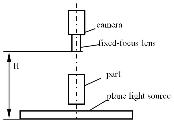
The roundness error was evaluated by using the end-face image; the quality of the obtained image will directly affect the detection precision of the whole measurement. Pictures were acquired by backlighting and using a CCD digital camera with a fixed-focus lens to improve image quality. The schematic diagram of image acquisition is shown in Fig. 1.
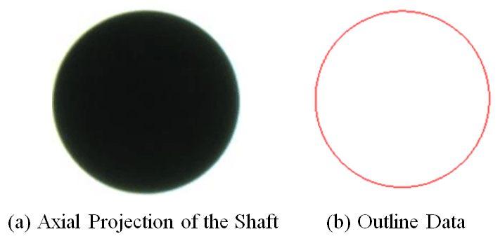
After obtaining the axial projection of the measuring part, part profile roundness data were obtained by graying and edge detection through machine vision technology. Figure 2 shows the procedure of the contour boundary extraction. Figure 2a shows the original picture from the camera. The part profile roundness data are presented in Fig. 2b.
2.2 Roundness error evaluation objective function
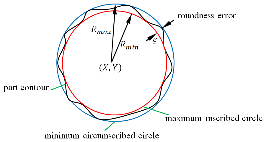
The set of contour boundary data points from the graph domain is denoted as , where (xi,yi) is the pixel coordinate position, and n is the serial number of the data point. Envelope sampling data points and the center position of two concentric circles with the minimum radius were determined. The roundness error was defined as the radius difference between the two concentric circles based on MZC (Fig. 3). The criterion can be as follows:
where e is the value of the objective function, i.e., the roundness error. (X,Y) is the center coordinate of the minimum area, (xi,yi) are data points for the collected part contour, and is the serial number of the data point.
3.1 Traditional bee colony algorithm
The traditional artificial bee colony (TABC) algorithm, an intelligent algorithm, completes the optimization process of the objective function through the cooperation of the population. The population is divided into the following three categories: leading bees, following bees, and scouting bees (Karaboga et al., 2014). First, the population is initialized, and parameter optimization is then carried out through the cycle iteration of leading bees, following bees, and scouting bees. The current optimal solution is regarded as the final result until the algorithm reaches the predetermined cycle number or meets the error condition. The algorithm implementation steps are as follows.
3.1.1 Initialize population
Generally, the initialized population is randomly processed to generate a new nectar source. The initial population is randomly described by Eq. (2).
where i is the serial number of the nectar source, j is the dimension of the solution space, , are the upper and lower bounds, and rand(0,1) is a random number in a range [0,1].
3.1.2 Leading bees
The leading bees randomly select one data value of generated nectar source. A new mining source is created based on Eq. (3). The fitness value of the new mining source, which represents the objective value, is evaluated by a fitness function in Eq. (4).
where xkj is the j dimension of the chosen neighborhood nectar, vij is the j-dimensional mining source of the selected nectar source, fi is objective function value, and fiti is the fitness function value.
3.1.3 Following bees
The significance of following bees is that mined the fitness value fiti corresponds to the nectar source. The following probability is proportional to the fitness value, which can be calculated by Eq. (5). After that, the nectar source is selected by following bees, and a new mining source is created by Eq. (3).
3.1.4 Scouting bees
If a nectar source is followed for a certain number of times, then the fitness value of the objective function fiti does not increase. The circumstance, falling into a local optimum, occurs, which means that leading bees need to be transformed into scouting bees. The nectar source is regenerated in the same way as the population initialization through Eq. (2).
3.2 Improved bee colony algorithm
The abovementioned TABC randomly generates the initial solution within the solution interval. The randomness, the global exploration ability, can be guaranteed. However, the rationality of the distribution of the initial population in the solution space is not perfect. Equation (2) shows that the new obtained solution depends on the quality of the random number. The result will probably cause a gathered phenomenon and an uneven distribution of the initialized population, thereby affecting the stability of the algorithm and iterative efficiency.
The improved bee colony algorithm (IABC) is proposed to improve the convergence accuracy of the algorithm for the solution of circle center coordinates. First, the local search domain is determined according to the original contour data. The convergent solution of the center of the circle is iteratively calculated by the step-decreasing method.
3.2.1 Definition of the local search domain
The population initialization region is determined according to the coordinates of the original contour data points to reasonably limit the search domain. It is equal to the solving range of the circle center. The specific steps are as follows.
The dimension of initialize population is , where the nectar source is , .
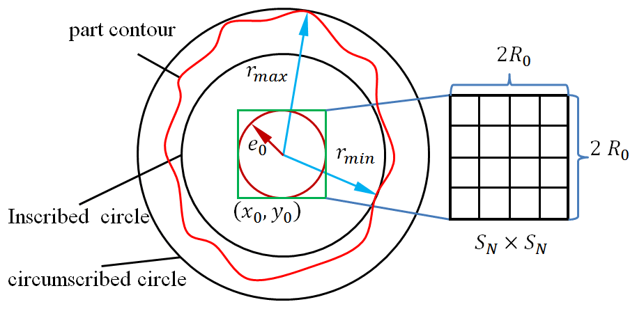
When solving the circumscribed circle and the inscribed circle, the initial circle center is obtained by Eq. (6) for the outer contour of the aforementioned part. More precise coordinates of the circle center are obtained by Eqs. (7) and (8).
where , n is number of data points, x0, y0 are the original coordinates of the circle center, rmax, rmin are the maximum and minimum distances from the initial circle center to the contour, respectively, e0 is the assumed initial roundness error, and R0 is the roundness error of the initial circle center, i.e., the radius of the region where the circle center is located.
The more uniform the initial solution distribution is, the more likely it is to search in the neighborhood of the optimal solution (Liu et al., 2017). The feasible region is divided evenly to ensure the uniformity of the initial population. A rectangular feasible region of the solution is constructed with the initial coordinates of the center of the circle (x0,y0) as the center and 2 times the error's assumed value e0, namely 2 R0, as the side length to facilitate uniform discrete processing of the circular region. We then divide it evenly into regions and take the center of each region as the initial solution of the colony algorithm, as shown in Fig. 4. The length of a single interval can be calculated by Eq. (9).
3.2.2 Step-decreasing search mechanism
The step-decreasing search method and the neighborhood search mechanism were adopted in the above uniform discrete interval. The purpose is to attract the following bees to iterate and update near the nectar source with a high adaptive value, guide the direction of random number, and improve the convergence speed of the algorithm.
In order to improve the solving efficiency of the algorithm and use the existing solution results, the step-decreasing search method was adopted. The nectar source update times t is introduced into the mining source update equation. With the increase in the nectar source mining times, the search range is gradually reduced to improve the solution accuracy. The ability of the local search domain was enhanced due to the parameter iteration in the two-dimensional space for an improved algorithm instead of the one-dimensional space for traditional algorithms. The search method of the new solution is shown in Eq. (10).
where xibest, yibest are the optimal solutions for the current nectar source, R is a random numbers in the range , and t is number of the nectar source update times.
3.2.3 Global optimal guidance
When the fitness value has not been updated continuously for t times, it demonstrates that it is trapped in a local optimum. A new solution needs to be randomly generated on the feasible region. In order to make full use of the previously generated initial population, the way of generating the initial population of TABC was improved based on the optimal individual guidance mechanism (Bansal et al., 2018). The optimal individual information generated by the previous iteration was introduced into the calculation formula of the next iteration. The expression of updated center solution is as follows:
where xibest, yibest is the optimal solution for the previous i iterations, Xmax, Xmin, Ymax, and Ymin are the feasible domain boundaries.

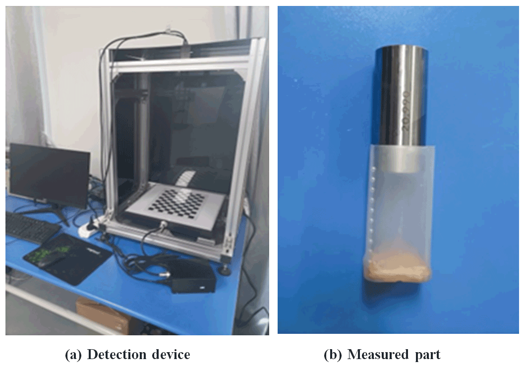
4.1 Experimental platform
A detection device was established according to the detection principle. Figure 6a and b show the detection device and pre-measured part, respectively. The camera model is a Basler ace acA4600-7gc, with a resolving power of 4408×3288, and the lens model is Basler C125-0818-5M-P, with a fixed focal length of 8.0 mm. The light type is planar light.
The calibration method (Zhang, 2000) was used to calibrate and correct the internal and external parameters of the camera using a checkerboard. The alignment of the shaft against the light source is a major concern in such vision-based systems. In order to solve this problem, this paper adopts the following methods: first, we adjust the camera angle according to the external parameters of the camera to make the optical axis of the camera perpendicular to the plane of the backlight. Then, by adjusting the parallelism between the stage and the light source plane to ensure the alignment of the axis and the light source, the part is placed in the center of the camera field of view to extract the edge coordinates. The roundness error of the 20.99±0.001 mm standard needle gauge parts was evaluated.
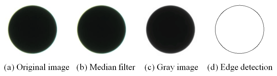
Image preprocessing and edge detection is as follows:
-
Image filtering. Using a median filter, the size of the filter core is 7×7. The results are shown in Fig. 7b.
-
Image graying. The weighted average method is used to transform the color image into a grayscale image, and the result is shown in Fig. 7c.
-
Edge detection. The backlight light source is used, most of the images are displayed in white, the parts to be tested are displayed in black, and the edges are step type. The contour is obtained by using adaptive threshold binarization (Yuan et al., 2016) and adaptive threshold Canny edge detection (Luo et al., 2009), and the results are shown in Fig. 7d.
The two-dimensional profile data were obtained by visual detection device, which was recorded as the point with 493 pixels, as shown in Table 1.

4.2 Verification
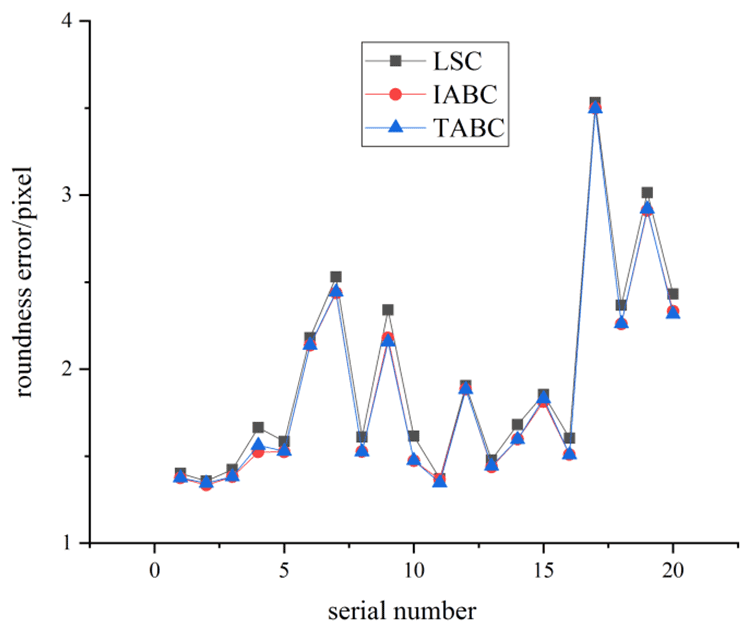
The accuracy of IABC was determined with the conditions of 50 as the total swarm size, 100 iterative numbers, and 15 as the maximum number of iterations of the same nectar source. The roundness error was calculated by the averaged value of running 50 times. Comparing the calculation of LSC and TABC, the results are recorded in Table 2.

As shown in Table 2, compared with the general LSC algorithm, the roundness error evaluation based on the IABC algorithm is smaller, which is in line with the smaller actual roundness error of the needle gauge. The comparison is shown in Fig. 8.
4.3 4.3 Comparative analysis with similar algorithms
A comparative analysis was conducted on the same set of measurement data in literature (Cui et al., 2006; Li et al., 2009) to further verify the effect of the proposed algorithm. The coordinates of data points are shown in Table 3.
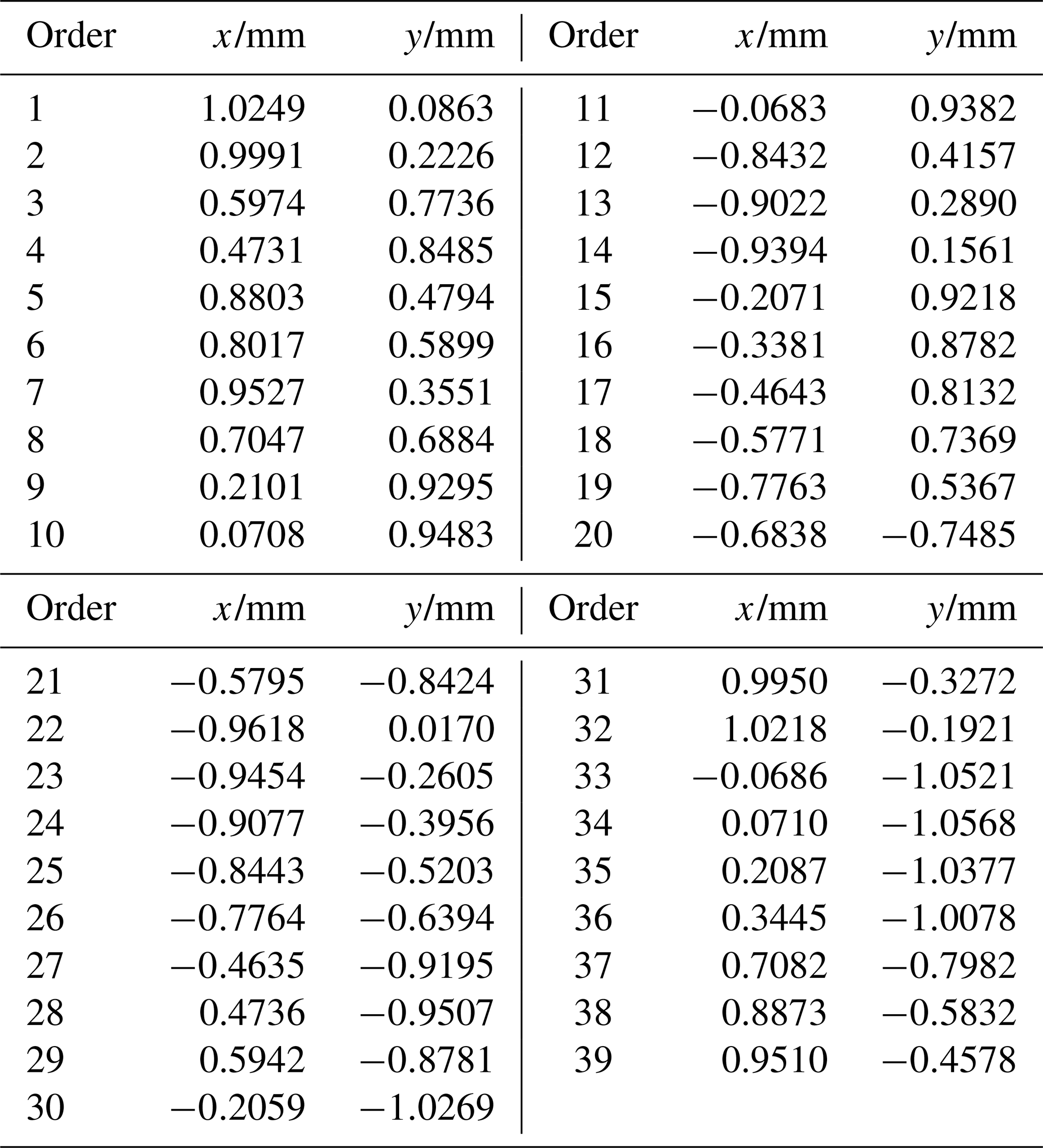
The relevant parameter settings of the algorithm in this paper are the same as those in Sect. 3.2. The evaluation results were compared with LSC (Li et al., 2009), PSO (Cui et al., 2006), GCSM (Yue et al., 2020), and MZC (Li et al., 2009), as shown in Table 4.
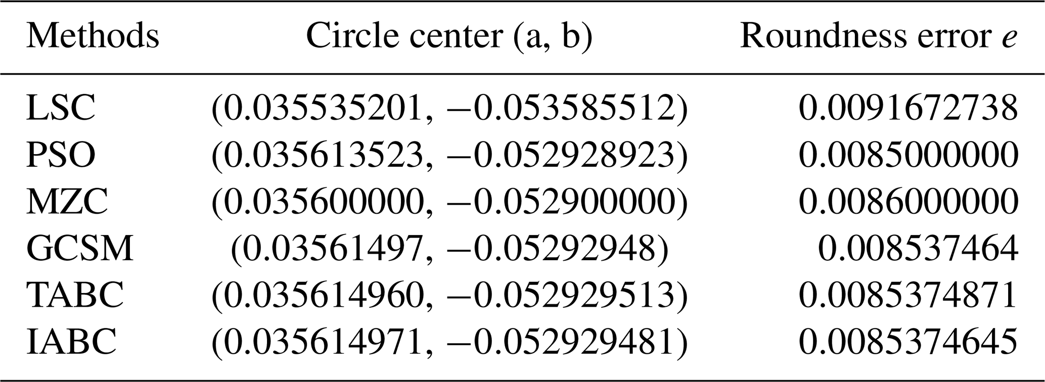
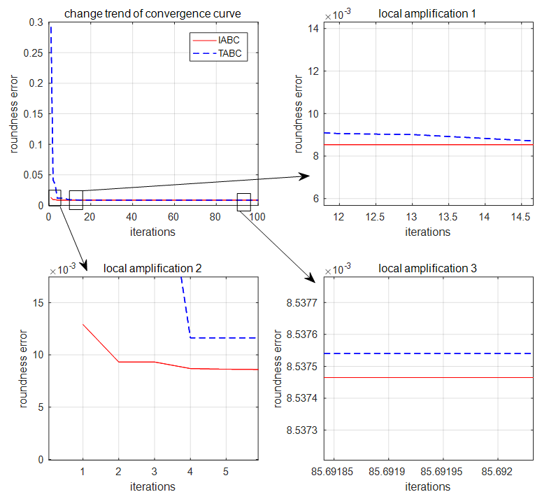
The results of the algorithm in this paper were close to the circle center position of LSC, the MZC method in the literature (Li et al., 2009), and PSO in the literature (Cui et al., 2006). Compared with the roundness error evaluation value of LSC (0.0091672738 mm), the evaluation value obtained by MZC in the reference (Li et al., 2009; 0.0086 mm), and the evaluation value of PSO in the reference (Cui et al., 2006; 0.0085 mm), the roundness error evaluation value (0.0085374645 mm) obtained in this paper is more accurate. Moreover, the center position and roundness error calculated in this paper have higher accuracy. It can be seen from the convergence diagram of the iteration curve in Fig. 9 that the initial solution obtained by the IABC is better than the TABC, with a faster convergence speed and a higher precision in the final solution.
IABC was proposed to solve the problem of the roundness error evaluation of shaft hole parts and the current insufficient accuracy of the roundness error evaluation. Population initialization, a search mechanism, and the optimal individual guidance were optimized. An experimental platform of the visual roundness error detection was established. A series of experiments were conducted to verify the superiority of the proposed method. Through evaluating standard needle gauges, the conclusion was drawn that the method was better than LSC. Additionally, comparative analysis were carried out based on LSC, PSO and MZC. The calculation results further showed that IABC had more feasibility and accuracy. Those conclusions demonstrate that the proposed method has certain theoretical and engineering value. In this paper, the roundness error of the part is calculated on the pixel surface. For the actual roundness error (µm), the following research plan includes subpixel edge detection to improve the precision of the part contour data. In this paper, it is considered that the original data obtained by machine vision technology are accurate, but due to the influence of camera distortion and environmental noise, the original contour data points of parts may have errors; this will bring some uncertainty to the result of the calculation.
Code and data can be made available upon request.
BJ provided the idea and wrote the revised draft of the paper. XD wrote the first draft of the paper. LW devised a scheme for the experiment. SB finished the analysis of the experimental data.
The contact author has declared that neither they nor their co-authors have any competing interests.
Publisher's note: Copernicus Publications remains neutral with regard to jurisdictional claims in published maps and institutional affiliations.
The authors would like to thank the National Natural Science Foundation of China for supporting this research.
This research has been supported by the National Natural Science Foundation of China (grant no. 52005003).
This paper was edited by Xichun Luo and reviewed by Abhilash Puthanveettil Madathil and one anonymous referee.
Bansal, J. C., Joshi, S. K. and Sharma, H.: Modified global best artificial bee colony for constrained optimization problems, Computers and Electrical Engineering, 67, 365–382, https://doi.org/10.1016/j.compeleceng.2017.10.021, 2018.
Cui, C. C., Huang, F. G., Zhang, R. C., and Li, B.: Roundness Error Evaluation Based on the Particle Swarm Optimization, Acta Metrologica Sinica, 4, 317–320, https://doi.org/10.3321/j.issn:1000-1158.2006.04.005, 2006.
Ding, L.: Design and application of roundness and cylindricity error evaluation algorithm, Xidian University, https://doi.org/10.7666/d.D363831, 2013.
Huang, F. G. and Zheng, Y. J.: A Method for Roundness Error Evaluation Based on Area Hunting., Acta Metrologica Sinica, 29, 117–119, https://d.wanfangdata.com.cn/periodical/jlxb98200802006 (last access: 20 June 2022), 2008.
Jadon, S. S., Bansal, J. C., Tiwari, R. and Sharma, H.: Accelerating Artificial Bee Colony Algorithm with Adaptive Local Search, Memet. Comput., 7, 215–230, https://doi.org/10.1007/s12293-015-0158-x, 2015.
Karaboga, D., Gorkemli, B., Ozturk, C., and Karaboga, N.: A comprehensive survey: artificial bee colony (ABC) algorithm and applications, Artif. Intell. Rev., 42, 21–57, https://doi.org/10.1007/s10462-012-9328-0, 2014.
Li, G., Niu, P., and Xiao, X.: Development and investigation of efficient artificial bee colony algorithm for numerical function optimization, Appl. Soft Comput., 12, 320–332, https://doi.org/10.1016/j.asoc.2011.08.040, 2012.
Li, X. M. and Shi, Z. Y.: The relationship between the minimum zone circle and the maximum inscribed circle and the minimum circumscribed circle, Precis. Eng., 33, 284–290, https://doi.org/10.1016/j.precisioneng.2008.04.005, 2009.
Li, X. M. and Shi, Z. Y.: Evaluation of roundness error from coordinate data using curvature technique, Measurement, 43, 164–168, https://doi.org/10.1016/j.measurement.2009.09.002, 2010.
Liu, X. F., Liu, P. Z., Luo, Y. M., and Fan, Y. L.: Improved artificial bee colony algorithm based on enhanced local search, CAAI Transactions on Intelligent Systems, 12, 684–693, https://doi.org/10.11992/tis.201612026, 2017.
Rajamohan, G. and Hoda, S.: Evaluation of circularity deviation from coordinate measurement data using an improved area hunting method, Mater. Today-Proc., 46, 7688–7694, https://doi.org/10.1016/j.matpr.2021.02.091, 2021.
Rossi, A. and Lanzetta, M.: Minimal Exhaustive Search Heuristics (MESH) of point clouds for form tolerances: the minimum zone roundness, Precis. Eng., 43, 154–163, https://doi.org/10.1016/j.precisioneng.2015.07.005, 2016.
Singh, D., Arunachalam, N., and Srinivasu, D. S.: A novel iterative-based field search technique for roundness evaluation, Procedia Manufacturing, 53, 268–275, https://doi.org/10.1016/j.promfg.2021.06.030, 2021.
Song, C., Jiao, L., Wang, X. B., Liu, Z. B., and Chen, H.: Improved Minimum Zone Circle Method for Roundness Error Evaluation of Shaft and Hole Parts, China Mechanical Engineering, 33, 1090–1097, https://doi.org/10.3969/j.issn.1004-132X.2022.09.011, 2022.
Tang, T., Teng, L., Wu, J., and Chen, M.: Realizing digitization in an all-round way is the only way to intelligent manufacturing reading “the road of intelligent manufacturing: digital factory”, China Mechanical Engineering, 29, 366–377, https://doi.org/10.3969/j.issn.1004-132X.2018.03.018, 2018.
Yuan, X. C., Wu, L. S., and Chen, H. W.: Rail image segmentation based on Otsu threshold method , Optics and Precision Engineering, 24, 1772–1781, https://doi.org/10.3788/OPE.20162407.1772, 2016.
Yue, L. L., Huang, Q. X., Mei, J., Cheng, R. J., Zhang, L. S., and Chen, L. J.: Method for Roundness Error Evaluation Based on Minimum Zone Method, J. Mech. Eng., 56, 42–48, https://doi.org/10.3901/JME.2020.04.042, 2020.
Zhang, C. Y., Lei, X. Q., Li, J. S., and Duan, M. L.: Method for Roundness Error Evaluation Based on Geometry Optimizatiion, J. Mech. Eng., 46, 8–12, https://doi.org/10.3901/JME.2010.12.008, 2010.
Zhang, X. C., Liang, T., and Tang, Y. M.: Roundness evaluation method based on error transformation and image domain, China Mechanical Engineering, 25, 1645–1650, https://doi.org/10.3969/j.issn.1004-132X.2014.12.016, 2014.
Zhang, Z. Y.: A Flexible New Technique for Camera Calibration, IEEE Transactions on Pattern Analysis and Machine Intelligence, 22, 1330–1334, https://doi.org/10.1109/34.888718, 2000.
Zhu, Y., Ling, Z. G., and Zhang, Y. Q.: Research progress and prospect of machine vision technology, Journal of Graphics, 41, 871–890, https://d.wanfangdata.com.cn/periodical/gctxxb202006002 (last access: 20 June 2022), 2020.
- Abstract
- Introduction
- Traditional roundness error evaluation model of MZC
- Roundness error evaluation based on improved bee colony algorithm
- Experiment
- Conclusions
- Code and data availability
- Author contributions
- Competing interests
- Disclaimer
- Acknowledgements
- Financial support
- Review statement
- References