the Creative Commons Attribution 4.0 License.
the Creative Commons Attribution 4.0 License.
 | 17 Jun 2022
Automation creation method for a double planet carrier gear train transplanting mechanism based on functional constraints
Liang Sun
Xuewen Huang
Yadan Xu
Zhizheng Ye
Chuanyu Wu
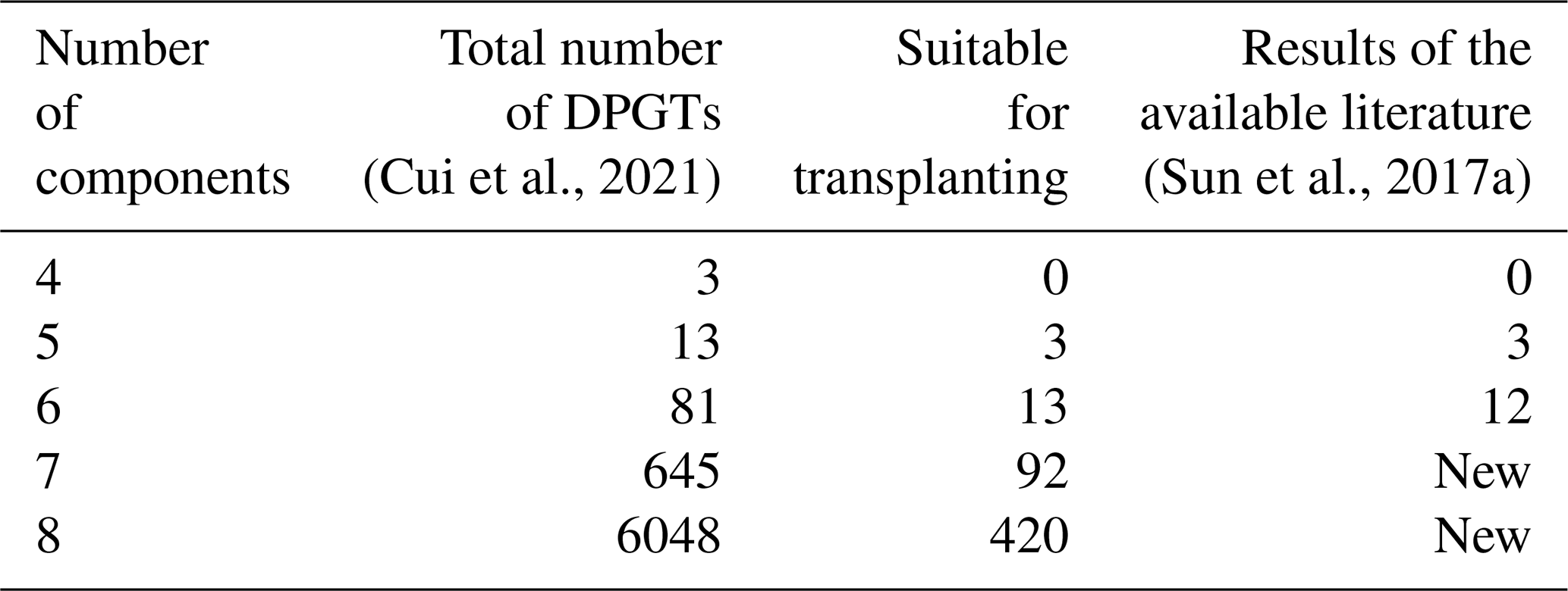
In order to satisfy the design requirements of diversified seedling transplanting mechanisms, this paper carried out systematic research on the creation method of planetary gear train mechanisms for transplanting based on the graph theory and the structural and functional characteristics of the transplanting gear train so as to establish a complete configuration atlas of a transplanting gear train. The structure and transmission ratio constraints of the planetary gear train for transplanting are established on the basis of the displacement graph of the planetary gear train. Selection methods for the planetary gear train rack, input, and output components are also proposed. The classification of three types of planetary gear trains is introduced by analysing the motion characteristics of the seedling transplanting mechanism, which realizes the systematic screening and classification of the double planet carrier gear train (DPGT) configuration. A total of 528 DPGTs, which are suitable for transplanting, including 3 five-bar, 13 six-bar, 92 seven-bar, and 420 eight-bar DPGTs are obtained. The problem of the single planet carrier transplanting mechanism not satisfying the requirements of a diversified transplanting trajectory is solved.
- Article
(1875 KB) - Full-text XML
- BibTeX
- EndNote


The seedling transplanting mechanism used in the transplanting machine is the core mechanism for simulating manual transplanting to complete picking, carrying, adjusting posture, planting, and other series of actions. Its working performance directly affects the quality of seedling transplanting. Therefore, in the design of the transplanting mechanism, the selection of the mechanism type that matches the agronomic requirements of seedling transplanting is the basis of the ideal trajectory, posture, and action required for seedling transplanting. Creating different transplanting mechanisms is often necessary due to the varieties and complexities of the seedling types and agronomic requirements (Zhang et al., 2013). However, this innovative design of personalized transplanting mechanisms is lacking in the research of seedling transplanting mechanisms. The existing gear train transplanting mechanism cannot satisfy the requirements of the different transplanting operations through dimensional optimization, thereby affecting the relevant research of seedling transplanting mechanisms.
Seedling transplanters can be divided into semi-automatic and automatic transplanters according to the automation level. The semi-automatic transplanters generally adopt a manual feeding operation and complete the planting operation with their transplanting mechanism. However, the automatic transplanters adopt a set or multiple sets of mechanisms to complete the feeding, carrying, and planting of seedlings and other series of transplanting actions. The automatic transplanters became the development direction of seedling transplanters (Yu et al., 2014) due to the advantages of high efficiency and stable transplanting quality. At present, the transplanting mechanism used in all types of transplanters mainly adopts multi-bar and gear train types (Xu, 2019). The multi-bar mechanism can obtain more transplanting trajectories through parameter optimization. However, the problems of high vibration and low operating efficiency exist due to the structural limitations of the linkage mechanism (Sun et al., 2019; for example, the vegetable pot seedling transplanting in a dry field is less than 50 plants per row per minute), which cannot satisfy the requirements of large field transplanting.
The planetary gear train mechanism has been widely used in seedling transplanting mechanisms due to its symmetrical structure, stable rotation, and efficient operation (Zhang et al., 2013). Yin et al. (2012) adopted a single planet carrier gear train by optimizing the centre distance of the gear, thereby realizing the large spacing transplanting of carpet seedlings by differential transmission. Zhu et al. (2014) proposed a new single planet carrier gear train transplanting mechanism by introducing a non-circular bevel gear into the helical staggered elliptic gear train and combining a reasonable transmission mode and sequence of spatial non-circular gear. The transplanting mechanism suitable for high-speed and wide–narrow distance is obtained through human–computer interaction optimization. Yu et al. (2012) presented a four-bar single planet carrier gear train by introducing elliptic gears and incomplete gear transmission to obtain vegetable pot seedling transplanting trajectories. Subsequently, Yu et al. (2013) presented another single planet carrier gear train with a concave and convex locking arc to obtain a special transmission ratio for rice pot seedling transplanting. Nevertheless, these transplanting mechanisms generally have a single configuration (single planet carrier gear train mechanism) with simple trajectory shapes. Although they have achieved favourable efficiency in the transplanting of rice carpet seedlings (400 plants per row per minute), they do not perform effectively in the application of pot seedling transplanting mechanisms with more complex trajectories. Compromising the continuity of gear transmission is often necessary to obtain the transmission ratio required for a particular trajectory and posture (Ye et al., 2017).
The double planet carrier gear train (DPGT) transplanting mechanism was gradually proposed considering the transplanting trajectories and postures. Takeyama (2007) adopted a five-bar DPGT, realizing the action of picking seedling and the posture of pushing seedlings. Sun et al. (2017b) proposed a non-uniform spatial planetary gear train by introducing non-circular gear and helical gear into a seven-bar DPGT. It achieved narrow–wide row spacing rice pot seedling transplanting with a complex spatial eight-shaped trajectory. Sun et al. (2019) proposed a design method of double planet carrier vegetable pot seedling transplanting mechanism based on an accurate four position set-up. A 3R (three revolute joints) solving model was established by considering the trajectory and transplanting arm posture. However, the innovative design of the existing double planet carrier transplanting mechanism mainly relies on the experience, intuition, and the trial mode of the designer but lacks a systematic design theory and method.
A suitable configuration is very difficult to find directly from the gear train atlas. Functional mechanism synthesis based on graph theory is an effective method for innovative mechanism design. For example, Chen (2020) proposed the screening conditions of a gear-train-type remote centre of motion mechanism by analysing the two-colour planetary gear train graph. The atlas of the virtual centre gear train with the potential of the remote centre of motion mechanism was obtained. Ding et al. (2012) obtained an innovative 11-bar 2 degrees of freedom (DOF) rode tractor by combining two six-bar 1 DOF mechanisms, which are similar to the existing mechanisms. Hu et al. (2013) synthesized the topological atlas of the foldable mechanism by analysing the topological characteristics of the foldable mechanism, and kinematic characteristics analysis and a motion performance evaluation of the configuration were carried out. Chen et al. (2018) analysed the topological synthesis graph of the motion chain for crank–rocker separation mechanism by a generalized processing method based on theoretical optimization conditions and a topological regeneration path design. In total, six topology graphs satisfying the design requirements of high pair kinematic chains were obtained, and the mechanism diagrams of separated kinematic chains were designed based on the basic chain topology design method. Xu et al. (2011) obtained the topological structure of the existing sofa bed by analysing its structure. The kinematic chain of eight links was obtained based on graph theory. The systematic creation method to obtain different configurations with the same function was proposed. Zhang et al. (2015) synthesized the configuration of fixed-axle gear train through the morphological analysis method and obtained the configuration scheme of an electrified mechanical transmission. The feasibility constraints and consistency conditions were defined by analysing the structure and function of EMT (electrified mechanical transmission), and the layout schemes and operating modes of various configurations were solved. Finally, a scheme meeting the structural and functional requirements was synthesized.
In the innovative design of the gear train transplanting mechanism, Liu (2017) proposed 1 DOF and 2 DOF screening criteria of a planetary gear train based on the double-colour graph. A total of 63 double-colour graphs of up to six-bars that satisfied the transplanting requirements were obtained. Xu (2019) presented a planetary gear train single-colour graph synthesis method based on the contracted graph interpolation point method. The planetary gear train double-colour graph was enumerated based on the single-colour graph. Finally, the planetary gear train for the transplanting mechanism was screened. However, these methods require human intervention in the reverse output transmission ratio analysis. The synthesized results of the available planetary gear train configurations were less than those of the six bar. In addition, the problem of the omission of applicable configurations exists.
Therefore, the automatic screening and creation method of the DPGT transplanting mechanism based on the adjacency matrix and functional constraints is carried out. A complete transplanting mechanism configuration atlas that satisfies the requirements of the diversified transplanting mechanism design is established.
The remainder of the article is organized as follows. Section 2 introduces the basic concepts of graph theory. Section 3 analyses the motion characteristics of the DPGT for transplanting. Section 4 proposes the creation constraints of DPGT transplanting mechanisms, including the structure constraints and transmission ratio constraints. The calculation method of the transmission ratio is introduced. The mechanism, which satisfies the constraints, is classified. Section 5 presents practical examples to verify the creation results. Section 6 presents the conclusion.
2.1 Labelled rotation graph and displacement graph
According to the representation of the gear train in graph theory (Yang et al., 2018), the Simpson gear train mechanism shown in Fig. 1a can be represented as labelled rotation graph (r graph), as shown in Fig. 1b. The solid vertex represents a component, the solid edge represents a revolute pair, the dashed edge represents a gear pair, the letters associated with the solid edges represent the position of the revolute pairs, and the same letters represent the coaxial revolute pair.
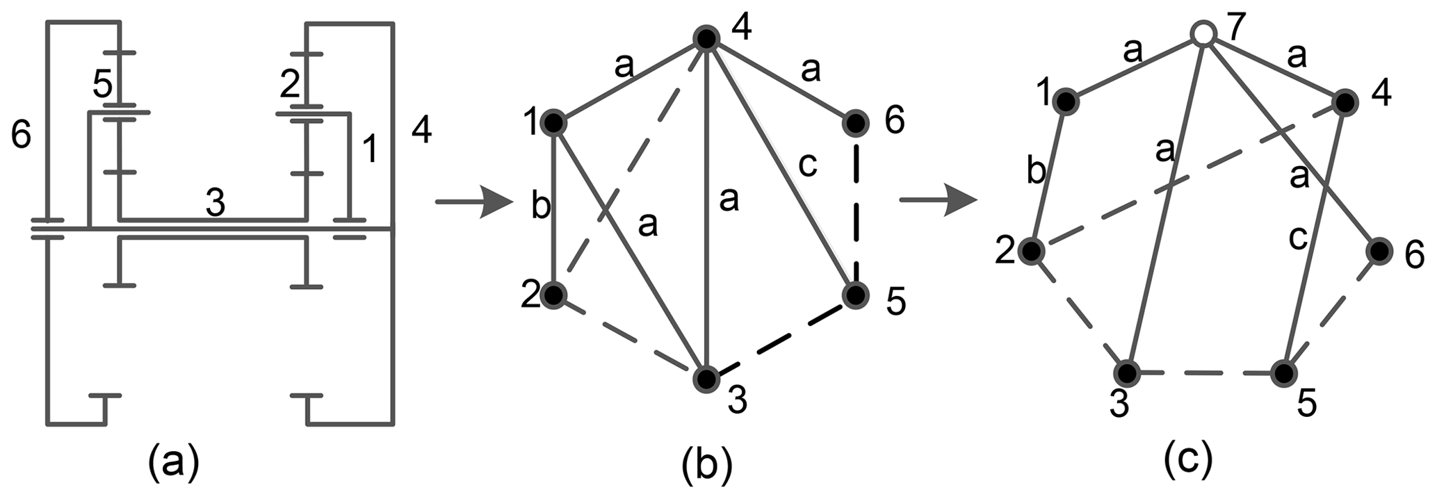
Figure 1(a) Simpson gear train mechanism diagram, (b) labelled rotation graph, and (c) displacement graph.
The adjacency matrix for a labelled rotation graph is defined as follows:
where n is the number of vertices on the graph. The adjacency matrix of Fig. 1b can be represented as follows:
According to Yang et al. (2018), if all solid vertices with the same level of edges are connected to a new common hollow vertex, then a displacement graph (d graph) without pseudo-isomorphism can be acquired. For example, Fig. 1c shows a d graph derived from Fig. 1b. The solid edge associated with the hollow vertex is represented by 2 to distinguish the r graph and d graph. Then, the adjacency matrix of the graph of Fig. 1c is as follows:
2.2 Tree and basic loop
The contacted and undirected graph without loops is defined as a tree. It is obtained from the d graph of the planetary gear train by deleting all gear edges. The corresponding unique basic loop is obtained by adding each gear edge to the tree. The number of basic loops is equal to the number of gear edges. All gear edges (dashed edges) of the Simpson gear train d graph in Fig. 1c are deleted. Then, dashed edges e23 e24 e35, and e56 are added successively to obtain four basic loops, as shown in Fig. 2c–f, where , , , .
2.3 Transfer vertex (planet carrier)
A transfer vertex exists in each basic loop. The solid vertex, except in the gear vertices, is the transfer vertex of the pair of gears. As shown in Fig. 2a, the basic loop has three solid vertices (1, 2, and 3), where vertices 2 and 3 represent gears, and vertex 1 is the transfer vertex of gears 2 and 3. The basic structure of a gear train can be obtained.
Figure 2(a) The tree and basic loops of the Simpson gear train. (b) The tree of the Simpson gear train, (c) basic loop f1, (d) basic loop f2, (e) basic loop f3, and (f) basic loop f4.
Figure 3 shows a DPGT transplanting mechanism (Takeyama, 2007) which is used for the integrated transplanting of vegetable pot seedlings in dry land.

Figure 3DPGT transplanting mechanism. (a) Transplanting mechanism schematic diagram. (b) Mechanism diagram.
The gear train on one side of the rotational centre can be used to describe the working principle of the mechanism because of its symmetrical characteristic. Figure 3b shows the mechanism diagram of a single-side gear train. The mechanism selects component 2 as the rack, component 1 (the first planet carrier) as the input component, and component 8 as the output component. Components 3 and 4 are meshed with component 2. Component 5 is meshed with components 3 and 7. Component 6 (the second planet carrier) is meshed with component 4. Component 8 is meshed with component 7. The planting arm is fixed to component 8. The transplanting trajectory is determined by the endpoint of the planting arm. When the first planet carrier rotates anticlockwise, the seedling paw on the planting arm picks and extracts the pot seedling from the pot tray and then plants it in the land.
In accordance with the motion characteristics of the mechanism, the following functional characteristics can be summarized to create a DPGT transplanting mechanism:
-
C1. The rack should be the component with only the gear function, and it should prioritize edge gears (only mesh with one gear). Otherwise, no-load gears become available. For example, in Fig. 3b, component 2 is selected as the rack, and component 8 is selected as the output. The no-load gear will not be generated.
-
C2. After selecting the rack, the input component shall select the component with the planet carrier function and rotate with the same level rack. For example, component 2 (gear) is the rack, component 1 (planet carrier) is the input, and components 1 and 2 have the same level revolute pair.
-
C3. The output component shall rotate in reverse rotation relative to the input component to facilitate the output component to realize a single ring or no ring motion trajectory (design requirement of transplanting trajectory). The output component shall select a gear without a planet carrier function. For example, if gear 2 is selected as the rack, then input component 1 turns anticlockwise, output component 8 turns clockwise, and then the gear train has a reverse output characteristic.
-
C4. The level of the revolute pairs of the output and input components should be different.
The functional characteristics of the mechanism can be related to the topological structure characteristics and transmission ratio law of the gear train. Therefore, the functional constraints of the mechanism creation of the DPGT transplanting mechanism are proposed based on topological structure and transmission ratio.
The overall constraints of the structure and transmission ratio required by the gear train transplanting mechanism Fa can be represented as follows:
where F1, F2 , F3, and F4 are structural constraints, and F5 and F6 are transmission ratio constraints. This finding indicates that the DPGT satisfies the basic motion requirements of the transplanting mechanism since it satisfies the structure and transmission ratio constraint conditions.
4.1 Structural constraint conditions
The meshing forms of the gears include internal meshing and external meshing. All the gears in the gear train adopt external meshing, considering the consistency requirement of the transmission gear (the pitch curve lengths of the meshed gear pairs are the same). Figure 4 shows an example to show the establishment of constraints.
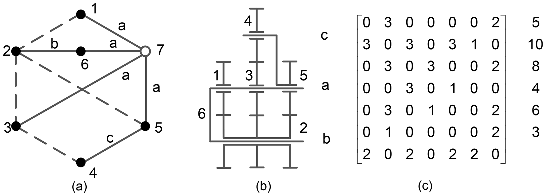
Figure 4Double planet carrier gear train. (a) The d graph, (b) mechanism diagram, and (c) the adjacency matrix of the d graph.
-
S1. The constraint conditions of the rack include selecting the component with only the gear function as the rack, without generating no-load gear.
-
Discussion 1. If component 5 is selected as the rack, then the gear train degenerates into a single planet carrier gear train. The fifth-row element in the adjacency matrix has three non-zero numbers (1, 2, and 3), where elements 1 and 2 indicate that component 5 is connected with two gears at different levels by revolute pairs. Component 5 is a planet carrier, according to the representation of the d graph. Thus, the corresponding component of the row only has the gear function when only elements 1 and 3 or 2 and 3 appear in a row of the adjacency matrix. When selecting component 5 as a rack, then there are two elements (1 or 2). Therefore, components 5 and 6 cannot be selected as a rack.
-
Discussion 2. Edge gears 1 and 4 are output components if gears 2 or 3 are selected as the rack. One of the edge gears must be a no-load gear because the transplanting mechanism has only one output. Hence, the condition that components 2 and 3 are used as the rack is not tenable.
-
Discussion 3. If edge gear 1 is selected as the rack and component 4 as the output, or component 4 as the rack and component 1 as the output, then the gear train does not have a no-load gear, and the corresponding row element of the component in the adjacency matrix satisfies the condition of rack selection. Therefore, components 1 and 4 have the potential to be selected as the rack.
The constraints of the rack selection of the d graph are defined as follows:
where Ad is the adjacency matrix of the planetary gear train d graph, nrack is the number of the rack vertex, and Ni is the number of elements 1 or 2 in the rack row. The constraint F1 shows that the number of elements 1 or 2 in the rack row is less than two.
-
S2. The constraint conditions of the input component are considered to select the vertex connected to the rack vertex by revolute pairs. The input and the rack must be connected by the same level of revolute pairs because the input component of the transplanting mechanism should be able to turn around the entire rack.
-
Discussion 1. The basic structure, consisting of vertices 1, 2, and 6 is expressed as , where the two numbers in the first set of parentheses represent meshing gears 1 and 2. The number 6 in the second set of parentheses represents the planet carrier that constrains the gear centre distance. In this basic structure, component 6 is connected to component 1 by a revolute pair. According to constraints on the rack, if gear 1 is determined as the rack, then component 6, which has the planet carrier function, can be selected as the input.
-
Discussion 2. Similarly, in the basic structure , gear 4 can be selected as the rack, and planet carrier 5 can be selected as the input component.
Therefore, in the basic structure, the constraints on the input component are defined as follows:
where nin is the number of the input component, and ni and nj represent the number of the two gears of the basic structure. nk represents the planet carrier of the two gears. Therefore, the input component can be directly determined by Eq. (4) after the rack is determined.
-
S3. The constraint conditions of the output component are as follows. First, the gear without the planet carrier function should be selected as the output component. The no-load gear does not exist. The following conditions should be satisfied to allow the transplanting mechanism to obtain a reasonable motion trajectory, that is, the output component must rotate in the opposite direction of the input component when the input component makes a full rotation.
-
Discussion 1. Component 5 has a planet carrier function and cannot be used as an output component.
-
Discussion 2. Gear 1 is selected as the rack, component 6 as the input component, and gears 2 or 3 as the output component; this condition is infeasible because no-load gear 4 is generated.
-
Discussion 3. Gear 1 is selected as the rack, component 6 as the input component, and gear 4 as the output component. There is no generation of a no-load gear. Therefore, gear 4 satisfies the constraint conditions of the output component.
Therefore, the constraints on the output component in the adjacency matrix can be expressed as follows:
where nout is the number of the output component, Nj is the number of elements 1 or 2 in an output row, and Nk is the number of the row in which the elements add up to 4 or 5. The constraint F3 indicates that the number of elements 1 or 2 in the output row is less than two, and the number of components, except the rack and output that elements add up to 4 or 5, should be equal to zero.
-
S4. The constraint conditions of the different levels of rotation axis of input and output components. The rotation axis of the output component should realize the full rotation relative to the axis of the rack. If the output component and the rack are at the same level, then the output and input components rotate coaxially; thus, the diversified transplanting trajectory design requirements are unsatisfied.
In Fig. 4, the solid vertices are divided according to their levels. The six solid vertices can be divided into three levels , , and . Assuming that component 1 is selected as the rack and component 4 as the output component with different levels of the two components 4 and 1 (component 1 belongs to the level La, and component 4 belongs to the level Lc), the selection of the input and output components is reasonable.
Therefore, the constraints of the different levels of input and output components can be expressed as follows:
where La and Lb indicate the number set of vertices in the same level.
In the mechanism creation, part of the results of the transmission path of gear train can be obtained using these constraint conditions. The complete transmission path selection of the gear train can be obtained by exchanging the rack and output component and determining the input component again based on constraint S3. According to this process, the entire transmission path of the planet gear train shown in Fig. 4 are as follows: , and .
4.2 Transmission ratio constraint conditions
-
S5. All the gear ratios should be included in the transmission ratio equations of the output and input components. As shown in Fig. 4, the planetary gear train has four pairs of gears, namely , , , and , and the corresponding gear transmission ratios are N21, N32, N43, and N52. After selecting the rack, input, and output components, the ratio of the angular velocity of the output component to the input component is the total transmission ratio. For example, (component 1 relative to component 5) contains the complete gear ratio of the gear train. Thus, the gear train is considered to satisfy the requirements of all gears in the transmission. This condition can be expressed as follows:
where Ad-u is the upper triangular adjacency matrix of the d graph, Nji is the transmission ratio of vertices i and j, and N is the set of all gear ratios in the total transmission ratio.
-
S6. The total gear transmission ratio is between 0 and 1. As shown in Fig. 4, when component 4 is selected as the rack and components 5 and 1 as input and output, respectively, then the total transmission ratio of gear train is . The total transmission ratio can satisfy the condition equal to zero due to the existence of the minus sign in the equation. The condition can be expressed as follows:
where ωout and ωin represent the angular velocity of the output and the input components, respectively.
4.3 Calculation method of the transmission ratio
As defined by the basic structure, the number of the basic structures is equal to the number of gear edges in the d graph, and each basic structure can construct an equation between the gear angular velocity and the transmission ratio.
As shown in Fig. 5, components i and j are gears, and component k is a planet carrier. A basic structure is constituted by components i, j, and k. The tangential velocity of the meshing points is the same, and the transmission ratio of the basic structure is defined as follows (Tsai, 2000):
where ωi, ωj, and ωk represent the angular velocities of components i, j, and k. Nji is the transmission ratio of gears j and i. The plus sign is considered if the gear is an internal meshing, and minus sign is considered if the gear is an external meshing.

As shown in Fig. 4a, the gear train has four gear edges, and the gear train has four basic structures, namely , , , and . The motion equations of the basic structures are established, and the transmission ratio equations of the entire planetary gear train can be obtained as follows:
Equation (10) is sorted out as follows (Wang et al., 2019):
If component 4 is selected as the rack, then the angular velocity of vertex 4 ω4=0. The column corresponding to vertex 4 in the coefficient matrix and the row corresponding to the angular velocity matrix from Eq. (11) are removed, and the following equation can be obtained:
Equation (12) solved , and the angular velocity matrix ω is calculated as follows:
In Fig. 4b, component 4 is selected as the rack, component 5 as the input, and component 1 as the output. The total transmission ratio of the planetary gear train is calculated as follows:
4.4 Classification of an applicable planetary gear train
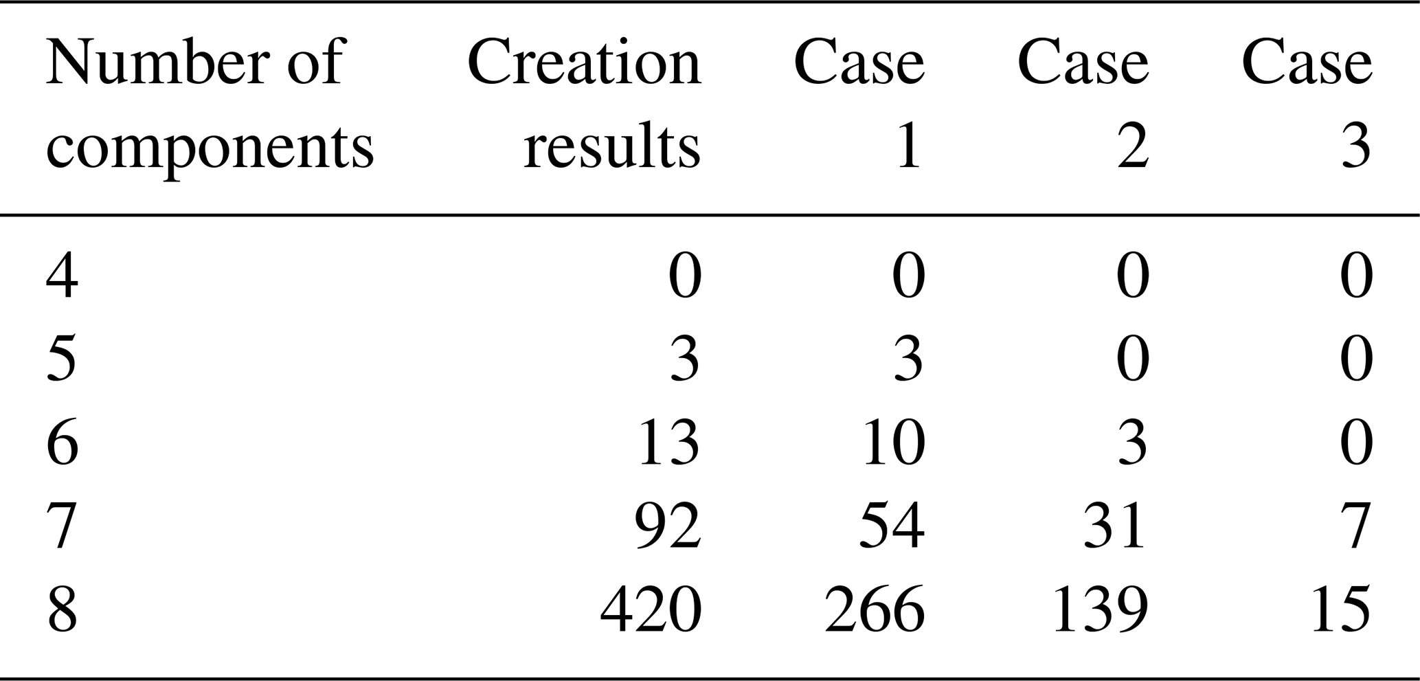
After the transmission path of a DPGT is determined, the three types of DPGT can be summarized by analysing the motion form of the output component. It is convenient for selecting an appropriate gear train in practical applications.
-
Case 1. The rack and output component only have different levels. The output motion form of this type of DPGT consists of the rotation of the second planet carrier around the rack axis, the output component around the second planet carrier, and the output around itself. As shown in Fig. 6, vertex 5 is selected as the rack, vertex 3 as the input, and vertex 6 as the output. Then, the motion form of vertex 6 is composed of three motion types (the circular motion of component 3 around the rotating axis of component 5, the circular motion of component 4 around the rotating axis of component 3, and its own rotation).
-
Case 2. The output component and the rack belong to different planet carriers. However, the rack and the output component planet carrier have the same level, or the output component and the rack planet carrier have the same level. The output motion of this type of DPGT consists of the rotation of the output around the rack and the rotation of the output. The second planet carrier no longer generates a full rotation of the output and only changes the rotation of the output. As shown in Fig. 4, vertex 4 is selected as the rack, vertex 5 as the input, and vertex 1 as the output. The motion form of vertex 1 consists of the circular motion around the rotation axis of component 4 and its own rotation.
-
Case 3. When selecting different components as rack, input, and output for the same gear train, Cases 1 and 2 appear in the same gear train. As shown in Fig. 7, the transmission path belongs to Case 2, and the transmission path belongs to Case 1.
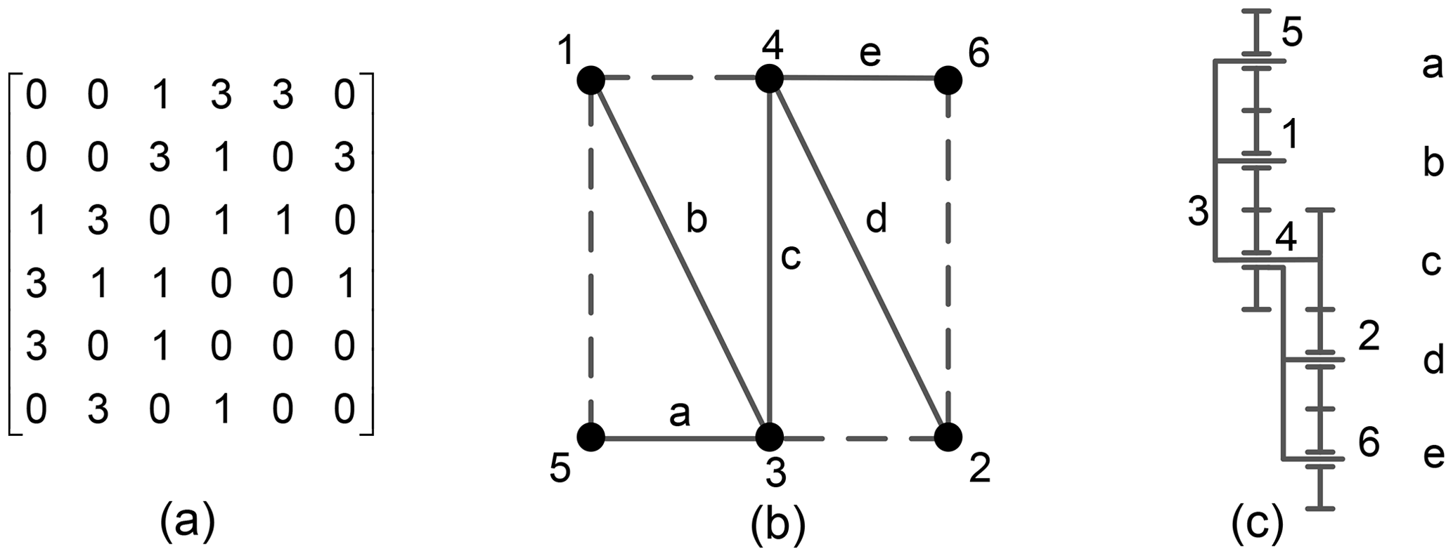
Figure 6Case 1 of the DPGT. (a) The adjacency matrix, (b) d graph, and (c) mechanism diagram.
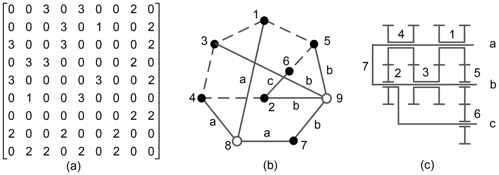
Figure 7Case 3 of the DPGT. (a) The adjacency matrix, (b) d graph, and (c) mechanism diagram.
4.5 Creation steps
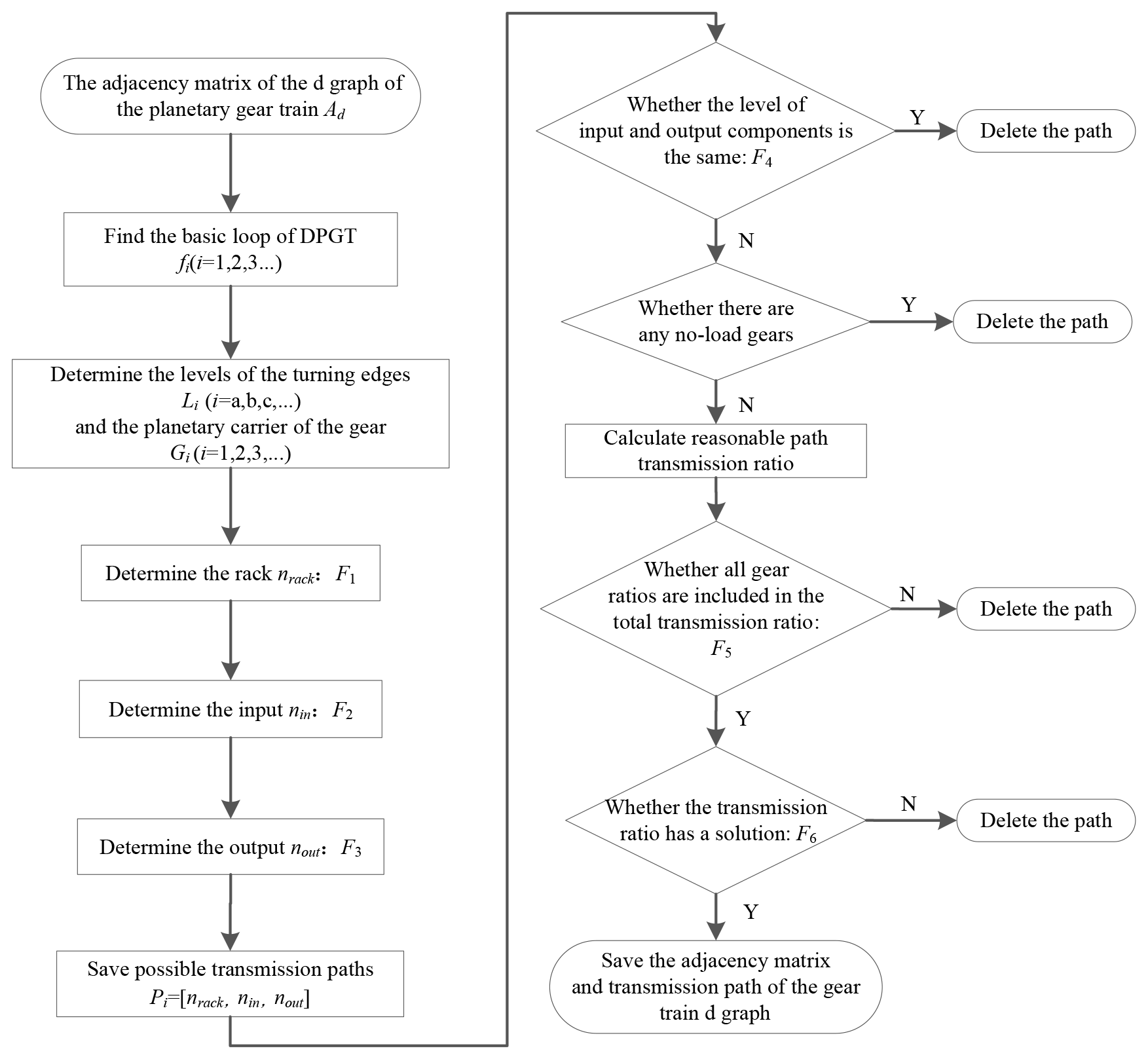
The constraints and classification of the DPGT are determined, and Fig. 6 illustrates the creation process of a DPGT according to the process shown in Fig. 8.
-
Step 1. A d graph adjacency matrix of a DPGT is selected, as shown in Fig. 6a.
-
Step 2. Basic loops are identified in the gear train.
-
Step 2.1. Gear pairs (element 3) are determined in the d graph upper triangular adjacency matrix, and the numbers of all gear pairs are recorded. The number of the gear pairs are , , , and .
-
Step 2.2. All gear edges are removed and then added, each in turn. The process starts at the first gear vertex of the gear pair, and the revolute edge is identified until the second gear vertex of the gear pair is returned through the revolute edge to obtain the basic loop. As shown in Fig. 6b, the basic loop of the gear train is , , , and .
-
Step 3. The corresponding transfer vertices of gear pairs are obtained by deleting the hollow vertices and gear vertices in the basic loop. The basic structures of the gear train shown in Fig. 6 are , , , and .
-
Step 4. The level of each gear axis is determined. According to the definition of the level of the d graph, the gear level shown in Fig. 6 is as follows: , , , , and .
-
Step 5. The rack, input, and output components of the gear train are determined. One of the vertices is selected as the rack. The input and output components are identified, and the transmission path is saved.
-
Case 1. If the gear train has two edge gears, then the two vertices must be the rack and output component.
-
Case 2. If the gear train has one edge gear, then the vertex must be the rack or output component. The gear train shown in Fig. 6 has two edge vertices (vertices with only one revolute edge and one gear edge), thereby satisfying Case 1. Vertex 6 is selected as the rack, vertex 5 as the output component, and transfer vertex 4 of vertex 6 as the input component. The transmission path is . Vertex 5 is selected as the rack, vertex 6 as the output component, and the transfer vertex 3 of vertex 5 as the input component. The transmission path is .
-
Step 6. The structure and transmission ratio are determined as being reasonable.
-
Step 6.1. Select one transmission path. Whether the level of the rack and output vertex is different or not is determined. If not, then it is saved, and the next step is performed. If yes, then the next path is selected, and Step 6.1 is repeated. The level of rack 6 of path P1 is different from that of the output component 5. The level of rack 5 of path P2 is different from that of the output component 6.
-
Step 6.2. Whether the entire gear ratios are included in the transmission ratio or not is determined. If all the gear ratios are included, then the next step is performed. If not, then the next path is selected, and Step 6.1 is repeated. The transmission ratios of path P1 and of path P2 contain four sets of gear ratios.
-
Step 6.3. The total transmission ratio of the transmission path is calculated, and whether the transmission ratio has a solution or not is determined. If a solution is obtained, then the next step is performed. If not, then the next path is selected, and Steps 6.1 and 6.2 are repeated. The solutions for the transmission ratios of path P1 and of path P2 are obtained.
-
Step 6.4. All reasonable paths are saved. If reasonable paths exist, then the gear train can be used for transplanting, and the d graph adjacency matrix of the gear train is saved. Finally, two reasonable paths , are obtained.
-
Step 7. The appropriate gear train is classified. Paths P1 and P2 match the type in Case 1.
5.1 Creation and classification results
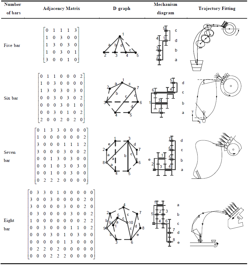
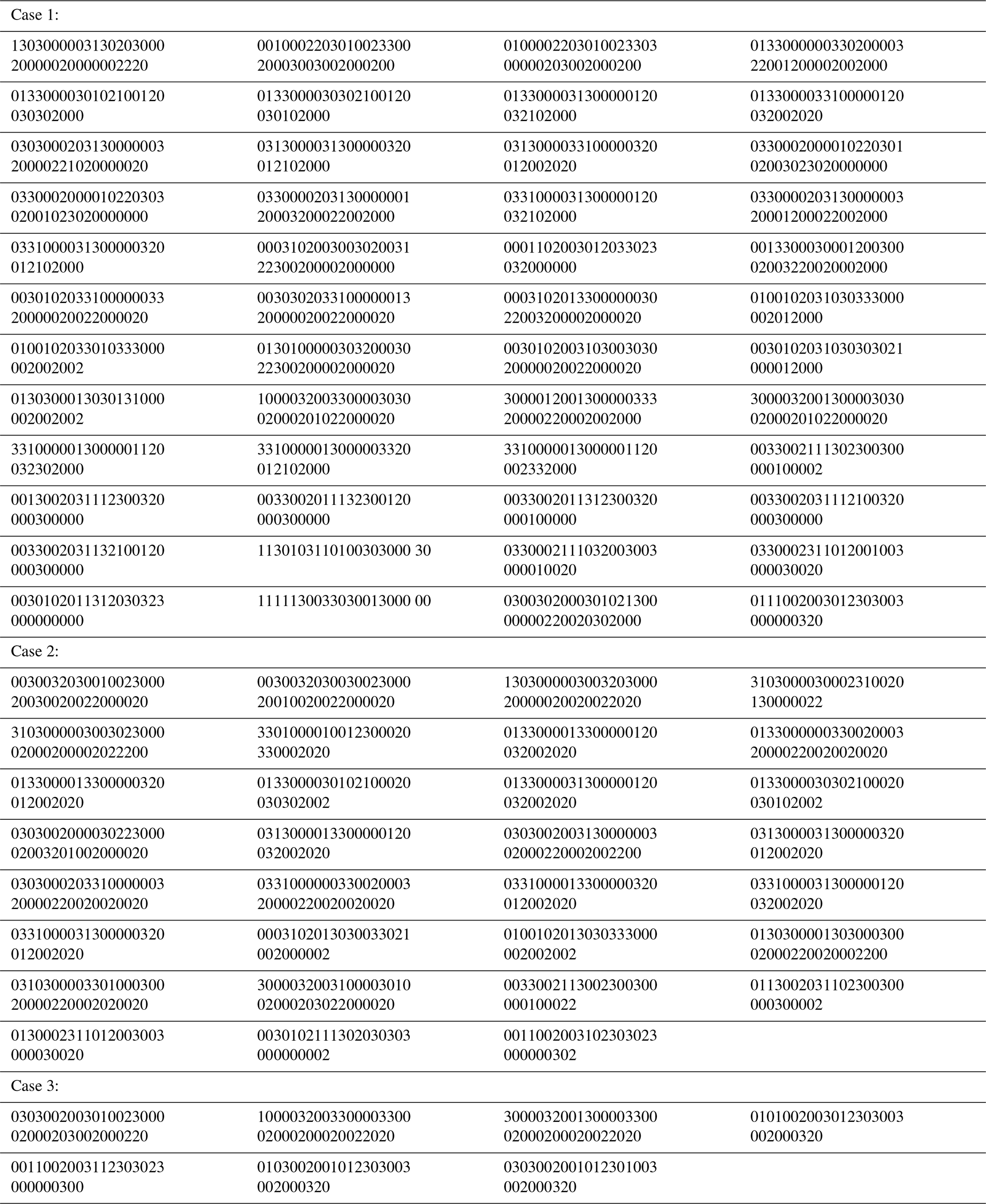
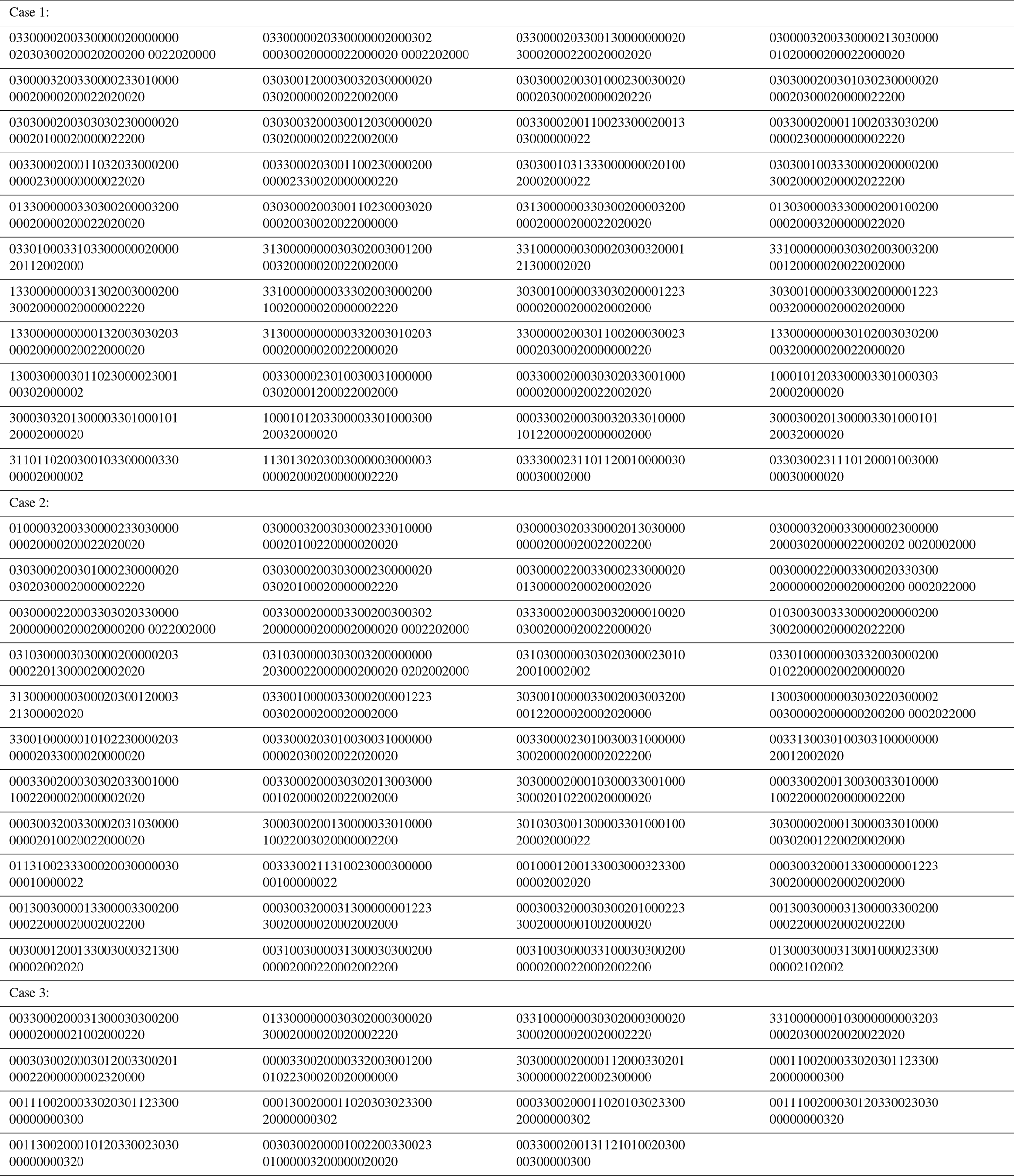
The creation method proposed in the previous chapter is used to create 1 DOF four- to eight-bar DPGT transplanting mechanisms. The specific results are shown in Table 1. The classified results are shown in Table 2. The results of the upper triangular adjacency matrix are shown in Appendixes B to E.
5.2 Special case analysis
The proposed five-bar DPGT is the same as that in Sun et al. (2017a). The DPGTs with seven and eight bars are the new results. The creation results of the six-bar DPGT have one more configuration. The d graph adjacency matrix, the d graph, and the mechanism diagram of this DPGT are shown in Fig. 9.
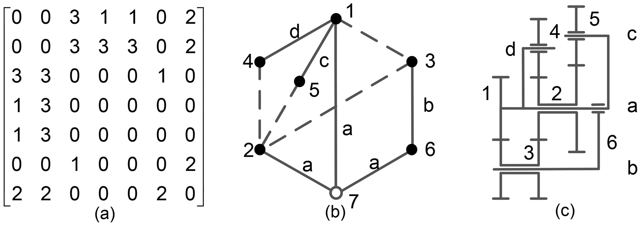
Figure 9One more gear train. (a) The adjacency matrix, (b) d graph, and (c) mechanism diagram.
According to the creation constraints of Sect. 4, gear 4 can be selected as the rack, component 1 as the input, component 5 as the output or as the rack, component 1 as the input, and component 4 as the output. The transmission paths and are obtained. By calculating the two transmission paths, the total transmission ratios are obtained as follows:
Both paths comply with the transmission ratio constraints.
5.3 Verification
The configuration atlas of the DPGT transplanting mechanism created and obtained is successfully used at present. For example, Liao (2021) designed a five-bar DPGT flower transplanting mechanism. Sun et al. (2017a) proposed a six-bar DPGT pot seedling transplanting mechanism, Sun et al. (2017b) presented a seven-bar wide–narrow rice pot seedling transplanting mechanism, and Zhao et al. (2021) presented an eight-bar DPGT potted flower transplanting mechanism. The adjacency matrices, d graphs, mechanism diagrams, and the kinematic trajectories are shown in Table 3. At the same time, various suitable DPGT mechanisms that can provide a feasible scheme for the innovative design of diversified seedling transplanters are found.
The creation method of 1 DOF DPGT transplanting mechanism was proposed based on the functional constraints. The structure and transmission ratio constraints based on the d graph adjacency matrix of gear train were constructed. Within the eight components of the DPGT, the automatic creation of the transplanting mechanism was realized. A total of 528 DPGTs, which are suitable for transplanting including 3 five-bar, 13 six-bar, 92 seven-bar, and 420 eight-bar configurations were obtained for the first time. The transmission paths for each available gear train configuration were provided. In addition, by analysing the motion form of the output gear of the gear train, the DPGT configurations were divided into three types. The classification results can facilitate the selection of different types of seedling transplanting mechanism designs. The complete available DPGT atlas within the eight bar can provide various schemes for the rapid design of diversified seedling transplanters.
| DPGT | Double planet carrier gear train |
| DOF | Degree of freedom |
| r graph | Labelled rotation graph |
| d graph | Displacement graph |
| Ar | The adjacency matrix of the labelled rotation graph |
| Ad | The adjacency matrix of the displacement graph |
| eij | The dashed edge connecting vertices i and j |
| f | The basic loop of planetary gear train |
| G | The basic structure of planetary gear train |
| F | The constraint conditions |
| nrack | The number of racks |
| nin | The number of input components |
| nout | The number of output components |
| The number of the i, j and k | |
| L | The number set of vertices in the same level |
| P | The transmission path of the gear train |
| g | The pair of meshing gears |
| Nji | The transmission ratio of gears j and i |
| N+ | The set of positive numbers |
| ωin | The angular velocity of the input component |
| ωout | The angular velocity of the output component |
Underlying research data are available upon request from the corresponding author.
All authors contributed to the study conception and design. The material preparation and data collection and analysis were performed by LS, XH, YX, ZY, and CW. The first draft was written by XH, and all authors commented on previous versions of the paper. All authors read and approved the final paper.
The contact author has declared that neither they nor their co-authors have any competing interests.
Publisher's note: Copernicus Publications remains neutral with regard to jurisdictional claims in published maps and institutional affiliations.
This research was funded in part by the National Natural Science Foundation of China (grant no. 51975534), in part by the 151 Talent Plan of Zhejiang Province, in part by the Project of Zhejiang Provincial Young and Middle-aged Discipline Leaders, and in part by the 2021 Zhejiang Province Public Welfare Technology Application Research Plan Project of “The digital synthesis and application of fusing structure constraints in gear system structure” (grant no. LGN21E050001).
This research has been supported by the National Natural Science Foundation of China (grant no. 51975534) and by the 2021 Zhejiang Province Public Welfare Technology Application Research Plan Project of “The digital synthesis and application of fusing structure constraints in gear system structure” (grant no. LGN21E050001).
This paper was edited by Guimin Chen and reviewed by three anonymous referees.
Chen, Y.: Synthesis and Design of Variable Remote Center of Motion Mechanism with Noncircular Planetary Gear Trains, MS thesis, Zhejiang Sci-Tech University, School of Mechanical Engineering and Automation, Hangzhou, China, https://doi.org/10.27786/d.cnki.gzjlg.2020.000834, 2020 (in Chinese).
Chen, Y. L., Hu, Y., Li, S. Y., and Shang, T.: Topology Optimization Analysis of Separation Mechanism for the Rice Trans-Planter, Math. Probl. Eng., 2018, 1–10, https://doi.org/10.1155/2018/6951647, 2018.
Cui, R., Ye, Z., Sun, L., Zheng, G., and Wu, C.: Synthesis method for planetary gear trains without using rotation graphs, Proc. Inst. Mech. Eng. Part C-J. Eng. Mech. Eng. Sci., 0, 1–12, https://doi.org/10.1177/0954406221998399, 2021.
Ding, H., Cao, W., Kecskemethy, A., and Huang, Z.: Complete Atlas Database of 2-DOF Kinematic Chains and Creative Design of Mechanisms, J. Mech. Design, 134, 031006, https://doi.org/10.1115/1.4005866, 2012.
Hu, M., Sun, B., Chen, W., Huang, D., Li, D., and Han, Y.: Structure Synthesis & Configuration Transformation of Variable Topology Repeated Foldable Wheel, IEEE International Conference on Robotics and Biomimetics (ROBIO), Shenzhen, PR China, 12–14 December 2013, WOS:000352739000015, 85–90, https://doi.org/10.1109/robio.2013.6739440, 2013.
Liao, H.: Design and Experiment Research Based on Solution Region Synthesis of Planetary Gear System Transplanting Mechansim with 3R Complete Rotation Kinemtic Pair, MS thesis, Zhejiang Sci-Tech University, School of Mechanical Engineering and Automation, Huangzhou, China, https://doi.org/10.27786/d.cnki.gzjlg.2021.000689, 2021 (in Chinese).
Liu, F.: Research on Structural Synthesis and Application of Gear Type Transplanting Mechanism Based on Graph Theory, MS thesis, Zhejiang Sci-Tech University, School of Mechanical Engineering and Automation, Huangzhou, China, https://kns.cnki.net/KCMS/detail/detail.aspx?dbname=CMFD201702&filename=1017042971.nh (last access: 10 June 2022), 2017 (in Chinese).
Sun, L., Chen, X., Wu, C., Zhang, G., and Xu, Y.: Synthesis and design of rice pot seedling transplanting mechanism based on labeled graph theory, Comput. Electron. Agric., 143, 249–261, https://doi.org/10.1016/j.compag.2017.10.021, 2017a.
Sun, L., Liu, B., Chen, X., Xu, Y., Mao, S., Wu, C., Zhang, G., and Jiang, H.: Design of differential transplanting mechanism for zigzag wide-narrow row rice pot seedlings, Trans. Chin. Soc. Agric. Eng., 33, 18–27, https://doi.org/10.11975/j.issn.1002-6819.2017.17.003, 2017b.
Sun, L., Shen, J., Zhou, Y., Ye, Z., Yu, G., and Wu, C.: Design of non-circular gear linkage combination driving type vegetable pot seedling transplanting mechanism, Trans. Chin. Soc. Agric. Eng., 35, 26–33, https://doi.org/10.11975/j.issn.1002-6819.2019.10.004, 2019.
Takeyama, T.: Vegetable transplanting mechanism, authorization proclamation: 21 November 2007, patent number: ZL200480007062.4, no. of authorization proclamation: CN100349504C, 2007.
Tsai, L.-W.: Mechanism Design: Enumeration of Kinematic Structures According to Function Taylor and Francis, 1 edn., Mechanical and Aerospace Engineering Series, CRC Press, ISBN: 0-8493-0901-8, 2000.
Wang, Z., Wang, X., and Zhang, J.: Calculation Method of Planetary Gear Train Transmission Ratio based on Adjacency Matrix, J. Mech. Trans., 43, 47–51, https://doi.org/10.16578/j.issn.1004.2539.2019.05.010, 2019 (in Chinese).
Xu, Y.: Type Synthesis and Design Method of Transplanting Mechanism with Epicyclic, PhD diss, Zhejiang Sci-Tech University, School of Mechanical Engineering and Automation, Huangzhou, China, https://doi.org/10.27786/d.cnki.gzjlg.2019.000353, 2019 (in Chinese).
Xu, S., Zhang, L., and Zhang, L.: Creative Design Based on Mechanism Regeneration of a Sofa Bed, Appl. Mech. Mater., 66–68, 442–447, https://doi.org/10.4028/www.scientific.net/amm.66-68.442, 2011.
Yang, W., Ding, H., Zi, B., and Zhang, D.: New Graph Representation for Planetary Gear Trains, J. Mech. Design, 140, 012303, https://doi.org/10.1115/1.4038303, 2018.
Ye, B., Yi, W., Yu, G., Gao, Y., and Zhao, X.: Optimization design and test of rice plug seedling transplanting mechanism of planetary gear train with incomplete eccentric circular gear and non-circular gears, Int. J. Agric. Biol. Eng., 10, 43–55, https://doi.org/10.25165/j.ijabe.20171006.2712, 2017.
Yin, J., Wu, C., and Liu, Y.: Optimization Design of Birotary Arm Type of Separating – transplanting Mechanism with Differential Eccentric Gear Train, China Mech. Eng., 23, 2930–2935, http://www.cmemo.org.cn/CN/Y2012/V23/I24/2930 (last access: 10 June 2022), 2012 (in Chinese with English abstract.
Yu, G., Chen, Z., Zhao, Y., Sun, L., and Ye, B.: Study on Vegetable Plug Seedling Pick-up Mechanism of Planetary Gear Train with Ellipse Gears and Incomplete Non-circular Gear, J. Mech. Eng,, 48, 32–39, https://www.semanticscholar.org/paper/Study-on-Vegetable-Plug-Seedling-Pick-up-Mechanism-Bing-liang-Zhiwei/18153bbc1e6d7edb327f1c53e77126a9582f57eb (last access: 3 June 2022), 2012.
Yu, G., Huang, X., Ye, B., Hu, H., and Yu, T.: Principle analysis and parameters optimization of rotary rice pot seedling transplanting mechanism, Trans. Chin. Soc. Agric. Eng., 29, 16–22, http://www.tcsae.org/nygcxb/article/abstract/20130303?st=article_issue (last access: 3 June 2022), 2013.
Yu, X., Zhao, Y., Chen, B., Zhou, M., Zhang, H., and Zhang, Z.: Current Situation and Prospect of Transplanter, Trans. Chin. Soc. Agric. Mach., 45, 44–53, https://doi.org/10.6041/j.issn.1000-1298.2014.08.008, 2014.
Zhang, H., Zhong, Z., and Chen, X.: Systematic synthesis method and prototyping of fixed-axle vehicular electrified mechanical transmission, Int. J. Auto. Techn., 16, 697–705, https://doi.org/10.1007/s12239-015-0070-x, 2015.
Zhang, K., Tao, Y., and Gao, K.: Research Advances and Characteristics in Transplanting Mechanism of High-Speed Transplanter, Adv. Mat. Res., 834–836, 1516–1522, https://doi.org/10.4028/www.scientific.net/amr.834-836.1516, 2013.
Zhao, X., Liao, H., Ma, X., Dai, L., Yu, G., and Chen, J.: Design and experiment of double planet carrier planetary gear flower transplanting mechanism, Int. J. Agric. Biol. Eng., 14, 55–61, https://doi.org/10.25165/j.ijabe.20211402.5878, 2021.
Zhu, J., Sun, L., Liu, X., Wu, C., and Zhang, B.: Design and optimization of transplanting mechanism with planetary gear train composed of helical gears and noncircular bevel gears, Trans. Chin. Soc. Agric. Eng., 30, 21–29, http://www.tcsae.org/nygcxb/article/abstract/20141103?st=article_issue (last access: 10 June 2022), 2014.
- Abstract
- Introduction
- Basic concepts
- Analysis of the movement characteristics of gear trains for transplanting
- Functional constraints of the mechanism creation
- Results and analysis
- Conclusion
- Appendix A: Nomenclature
- Appendix B
- Appendix C
- Appendix D
- Appendix E
- Code and data availability
- Author contributions
- Competing interests
- Disclaimer
- Acknowledgements
- Financial support
- Review statement
- References