the Creative Commons Attribution 4.0 License.
the Creative Commons Attribution 4.0 License.
 | 14 Jun 2022
Design and kinematic analysis of a multifold rib modular deployable antenna mechanism
Dake Tian
Haiming Gao
Lu Jin
Rongqiang Liu
Yu Zhang
Chuang Shi
Jiewei Xu
Aiming at the urgent need for the development of space deployable antenna with large aperture and a high storage rate, a new configuration of a multifold rib modular deployable antenna mechanism is proposed. The overall structure scheme design of the antenna is carried out, and the structure composition of the module, the principle of structural topology transformation, and the scheme of mechanism deployment and locking are expounded. According to the shape and constraint relationship of the structure deployment and folded state, and based on basic theory of robotics, calculation and the analysis of key structural parameters and the included angle of rib units are carried out, and the parameterized mathematical model is established. The detailed structural design is carried out, and then the complex structures such as the center beam assembly, diagonal beam assembly, and outer beam assembly are introduced in detail. The kinematic simulation of the mechanism is carried out by using ADAMS software, and the variation law of the motion parameters is analyzed. Finally, the prototype of a hexagonal prism single-module principle is developed, and a deployment function test and verification are carried out. The simulation and test results show that the proposed mechanism can realize the motion change from folded to deployed, and no problems such as interference or clamping are observed in deployment, which verifies the correctness and the feasibility of the structural scheme and principle. Moreover, the proposed new configuration scheme not only retains the characteristics of modular structure, such as good universality and easy expansion, but also has a high storage rate and structure efficiency rate. The research results have a high reference value and relevance for basic theoretical research and the engineering application of a space deployable antenna.
- Article
(14031 KB) - Full-text XML
- BibTeX
- EndNote


A space deployable antenna is a new type of space structure and one of the key payloads of spacecraft which is widely used in mobile communication, navigation and remote sensing, deep space exploration, military reconnaissance, and other fields of science and technology and national defense (Morozov et al., 2022; Guo et al., 2022). Owing to the limitation of the vehicle volume, a space deployable antenna is in a folded state during the launch, and it is gradually deployed and locked after entering the orbit, according to the control instructions, to form a large-scale space structure. According to the different working surface media, deployable antennas have the following three different types: solid-surface antennas (Fedorchuk and Arkhipov, 2014; Huang et al., 2018), inflatable antennas (Chandra et al., 2021; Eliseeva et al., 2022), and mesh antennas (Datashvili, 2013; Liu et al., 2018; Shi et al., 2018). Mesh antennas have many advantages such as a high storage rate, light structure weight, large deployment aperture, and high shape accuracy due to the use of a linkage mechanism as the supporting structure of the antenna deployment (Liu et al., 2020). The mesh antenna has become one of the most active and widely used structures in the field of deployable antennas.
The configuration design of the mechanism is one of the key research directions of mesh deployable antenna. Local and international aerospace agencies and scholars have paid high attention to this topic and carried out in-depth research, and several models have been applied in orbit. Among them, the representative antennas are mainly as follows: the National Aeronautics and Space Administration (NASA) has designed and developed a radial rib deployable antenna (Hanayama et al., 2004), which is supported by several parabolic tubular carbon fiber ribs attached to a central hub, and looks like an umbrella-type shape after deployment, and the reflective mesh is connected between these ribs. It has been used in NASA Tracking and Data Relay Satellite (TDRS) and the NASA Galileo mission. The antennas constructed for TDRS and Galileo are almost identical, with a diameter of 5 m. The Jet Propulsion Laboratory (USA) developed the wrap-rib deployable antenna on Applications Technology Satellite 6 (ATS-6; Semler et al., 2010). The antenna consists of multiple hollow radiating ribs. In the folded position, the ribs are rotated on the central hub, and the stored energy in the ribs causes them to unwrap into their original position. The deployment aperture of the antenna is up to 9.1 m. The foldable rib deployable antenna (Santiago and Baier, 2013) is designed by the Harris Company (USA) for TerreStar-1 satellite and consists of several foldable ribs. The ribs are deployed in a straight line, the reflecting surface is formed into a paraboloid by the supporting beams on the ribs, and the deployment aperture can reach 18 m. The ring truss deployable antenna (Mehran et al., 2012; Brown, 2016) developed by Astro Aerospace (USA) is composed of several quadrilateral elements, and the antenna is deployed by shortening a cable that continuously runs through the telescopic diagonal members of the ring truss. Deployment synchronization is achieved through special joints at the ring truss connections. It has been applied to the Thuraya satellite, and the deployment diameter is 12.25 m. The truss structure deployable antenna (Ozawa, 2010; Tomoyuki et al., 2011) was developed by the Japan Aerospace Exploration Agency (JAXA) for the Engineering Test Satellite VIII (ETS-VIII), which is composed of several hexagonal prism modules. The deployment of the antenna depends on the elastic potential energy released by the compression spring installed in the mechanism. In its deployed configuration, the diameter is 20 m in the major axis. The Russian company OKB-MEI (Chebotarev et al., 2014) developed a framework deployable antenna composed of tetrahedral modules, and the antenna structure is composed of many tetrahedral modules. The deployment of the antenna depends on the scroll spring installed at the connecting node. The deployment aperture of this kind of antenna is generally 4–10 m. It has been successfully applied in satellite platforms such as RESURS-O satellite and Mir space station. The truss antenna developed by the China Academy of Space Technology (Zhang and Jiang, 2014; Zheng et al., 2014) is composed of tetrahedral units, where each module includes diagonal beams and folding beams, and the elastic potential energy stored by elastic hinges is used to complete the mechanism deployment. The antenna has been successfully applied to HJ-1C (Huan Jing 1C) satellite, with a deployment aperture of 6 m × 2.8 m. The loop truss deployable antenna (Li et al., 2016; Ma et al., 2019) jointly developed by the Beijing Institute of Technology and the China Academy of Space Technology (Xi'an) takes the parallelogram mechanism as a module unit, utilizes the telescopic characteristics of the quadrangle diagonal, and uses the motor to pull the cable to realize the mechanism deployment. The deployment aperture is 15.6 m.
In recent years, with the rapid development of space technology, the demand for new deployable antennas with a large aperture, high storage rate, and high structural efficiency rate has become more urgent. Large-aperture deployable antennas with excellent comprehensive performance and deployment sizes of 30–100 m have become the main development direction (Luo et al., 2018; Yang et al., 2020). The modular structure has good universality and high flexibility. By changing the shape, size, number, combination, and arrangement of modules, the antenna aperture can be rapidly scaled. It is an ideal structure for large-diameter deployable antennas in the future (Krishnan et al., 2012). However, the research and application of modular structures in the field of deployable antennas are less common; most of the abovementioned typical deployable antennas are single-module structures, where the limitations of the whole antenna are evident, and most of them show strong structural coupling and poor expansion, with the deployment of small diameters and other unfavorable characteristics. JAXA developed a modular deployable antenna consisting of 14 hexagonal prism modules on ETS-VIII (Ozawa, 2010), but its effective aperture is only 13 m, and its folded height reaches 4 m. The efficiency rate of the antenna structure is relatively low, and the folding height is relatively high. Achieving a good consideration and balance in terms of multiple demand indicators is difficult for the existing typical mesh-type deployable antenna, and adapting to the needs of future development is difficult.
To meet the development needs of deployable antenna in the future, such as a large aperture, modularity, and high storage rate, this paper proposes a new configuration of a multifold rib modular deployable antenna mechanism and carries out the innovative design of the configuration and its kinematic analysis. The remainder of the paper is structured as follows: in Sect. 2, the structural scheme design is carried out, and the mechanism is designed from the aspects of the structural composition, design principle, deployment, and locking. In Sect. 3, the structural parameters are calculated, and the key parameters of the mechanism are determined by using the theory of spatial geometry and robotics. In Sect. 4, the structure of the deployable antenna is designed in detail, several design difficulties are selected for analysis, and the 3D model of the mechanism is established. In Sect. 5, the kinematic simulation analysis of the mechanism is carried out by using ADAMS software, and the variation law of motion parameters is studied. In Sect. 6, the development of the principle prototype is introduced, and the deployment function test of the mechanism is carried out. Finally, conclusions are drawn in the last section.
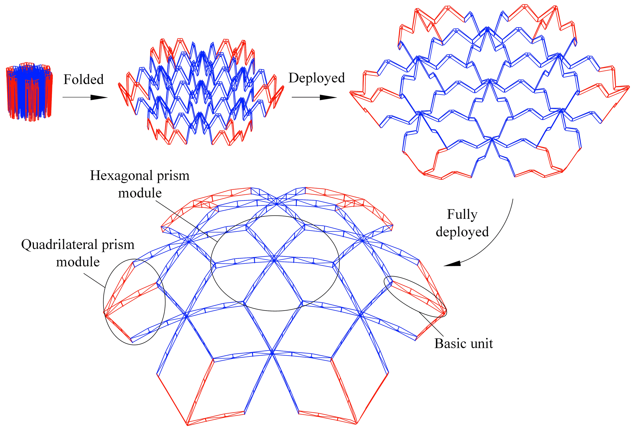
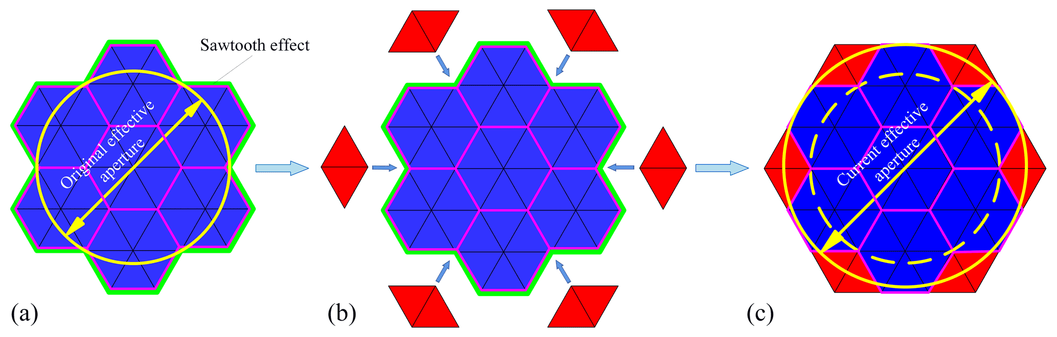
Figure 2Comparison of the effective aperture of a single configuration and multiple configuration. (a) Single configuration. (b) Multiconfigurational combination. (c) Multiconfigurational combination.
2.1 Overall scheme
According to the requirements of a large aperture and high storage rate of deployable antenna, combined with the examples of a multifold umbrella and a multisectional fishing rod in peoples' lives and the advantages of a modular structure, an innovative design scheme of a multifold rib modular deployable antenna mechanism composed of quadrangular prism module and hexagonal prism module is proposed, as shown in Fig. 1. The proposed mechanism consists of 13 modules, including 7 hexagonal prism modules and 6 quadrangular prism modules. Both types of modules use the same rib unit as the basic deployable unit (referred to as a basic unit for short). The module uses springs as the power source and relies on the elastic potential energy stored after the spring is compressed to drive the mechanism to deployed. The interior and the edges of each module are given tension with tension cables to improve the rigidity of the structure after deploying, and the included angle between basic units can be ensured.

On the basis of retaining the advantages of good interchangeability and easy the expansion of modular structure, this structural scheme also has two outstanding advantages. First, the basic unit adopts a three-fold form, which greatly reduces the height of the folded antenna and is beneficial for the large-scale development of a single module. Second, the overall structure scheme adopts a multiconfiguration scheme composed of the following two configuration modules: a quadrangular prism and a hexagonal prism. This design has the advantages of overcoming the problems of the low structural efficiency rate and the small effective aperture of the original single hexagonal prism configuration. The new scheme adopts the patching design idea, and the uneven sawtooth effect existing at the edge of the structure of the original single configuration is patched by introducing the quadrangular prism patching module. After the combination of the two configurations, the shape of the antenna is closer to the circle, and the effective aperture is clearly increased, as shown in Fig. 2.
2.2 Structure composition and deployment principle
The multifold rib modular deployable antenna mechanism is decomposed into modules, and the hexagonal prism module unit is shown in Fig. 3. The three-fold structure is used as the rib unit, each module consists of six rib units, and the rib units are distributed radially around the center of the module. Owing to the large radial deployment scale of the rib unit, the layout scheme of double-layer tension cables is adopted at the interior and the edge of the module to ensure the rigidity of the mechanism after deployment. The tension cable adopts the cross-connection method. After the support mechanism is fully deployed, the tension cable provides a certain pretightening force, thereby improving the rigidity of the entire mechanism after deployment, ensuring the angle between the rib units and increasing the deployment stability. The overall structure principle of the quadrangular prism module is similar to that of the hexagonal prism module. Except that the number of rib units is changed to three, the remainder of the tension cable arrangement and rib unit structure are the same as those of the hexagonal prism module, which is not repeated here.
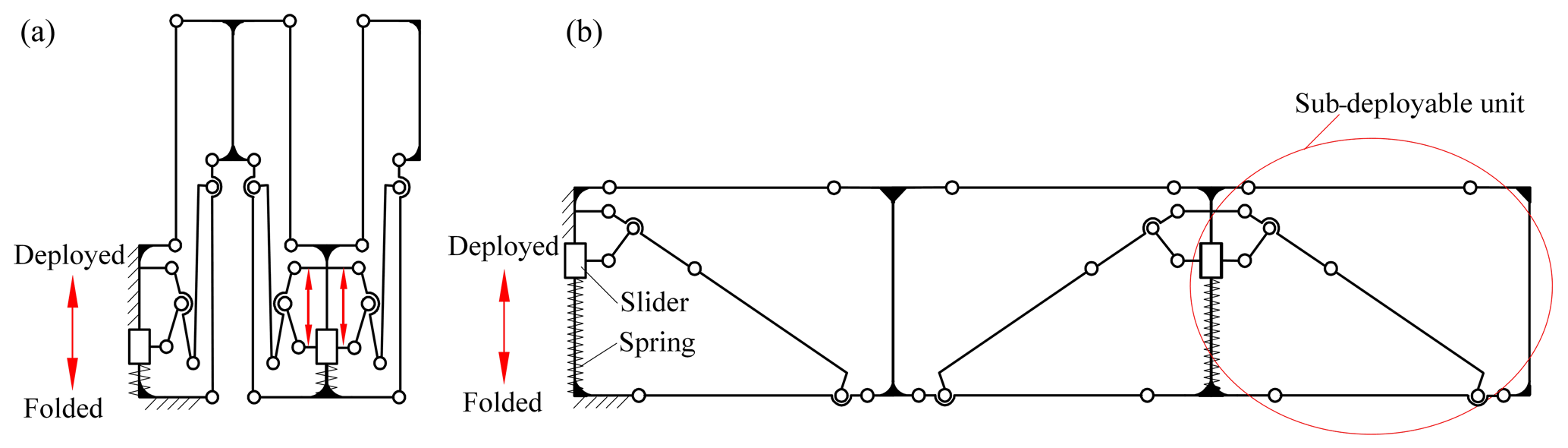
Figure 4 shows the rib unit structure, which can be regarded as consisting of three sub-deployable units with a similar structure and being connected in series. Among them, the first deployable unit and the second deployable unit share one outer beam, and the second deployable unit and the third deployable unit adopt the same central beam. The structure uses a spring as the power source to provide the driving force, and each rib unit includes two springs, where one drives one sub-deployable unit, and the other spring drives the two other sub-deployable units. During the deployment process, the central beam remains fixed, and other structures are gradually deployed under the drive of elastic potential energy. When the mechanism unfolds to the extreme position at the end, the whole mechanism is locked, and the basic unit becomes a stable structure.
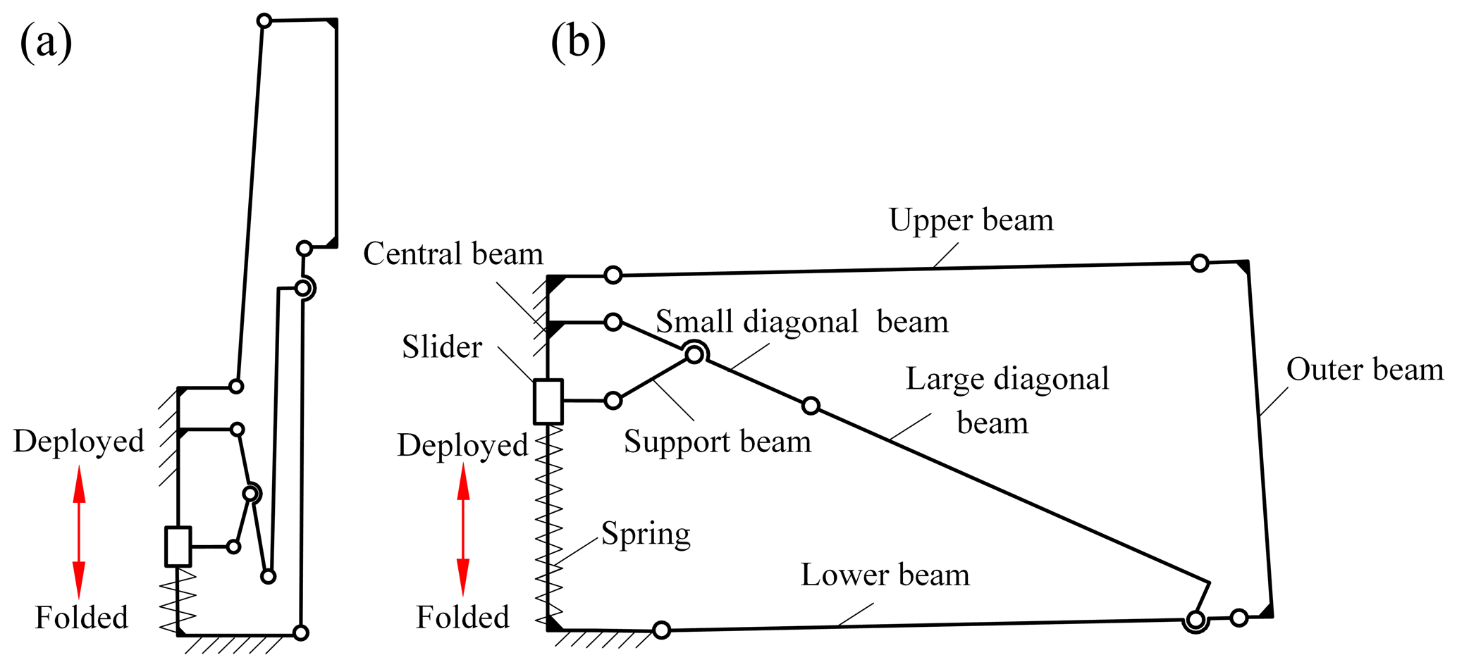
To explain the deployment principle of the mechanism more clearly, the rib unit mechanism in Fig. 4 is further decomposed to obtain the sub-deployable unit shown in Fig. 5, which is the smallest deployable unit, and its structure is mainly composed of central beam, slider, support beam, upper beam, outer beam, lower beam, small diagonal beam, large diagonal beam, and other structures. When the sub-deployable unit is folded, the center beam, the upper beam, and the outer beam are distributed along parallel lines, and the outline of the structure is cylindrical. During the deployment of the mechanism, it can be regarded as the 2D movement of the mechanism; that is, the driving spring releases the potential energy to drive the slider upward, and it drives the support beam to rotate from the center to the side, and the other beams are deployed synchronously. When the axes of large and small diagonal beams are in the same straight line, the mechanism is fully deployed and locked.
3.1 Calculation of rib unit parameters
The curvature of each point on the parabola is different because the reflector of the antenna is generally parabolic. If the key points of the rib unit are placed on the parabola, the sizes and the angles of the upper beam and the lower beam of each rib unit are different, which is not conducive to the realization of modular design, and realizing the synchronous deployment among mechanisms is difficult. Based on previous studies, using the idea of a spherical fitting parabola (Tian et al., 2010), the parabola is fitted by an arc, and then the structural parameters of the rib unit are determined. Figure 6 shows the relationship between the sphere and the paraboloid. Taking the fitting sphere center O as the coordinate origin, a rectangular coordinate system {O} is established according to the right-hand rule, where R is the radius of the fitted sphere, and l is the radius of the outer enveloping circle in the deployed state.
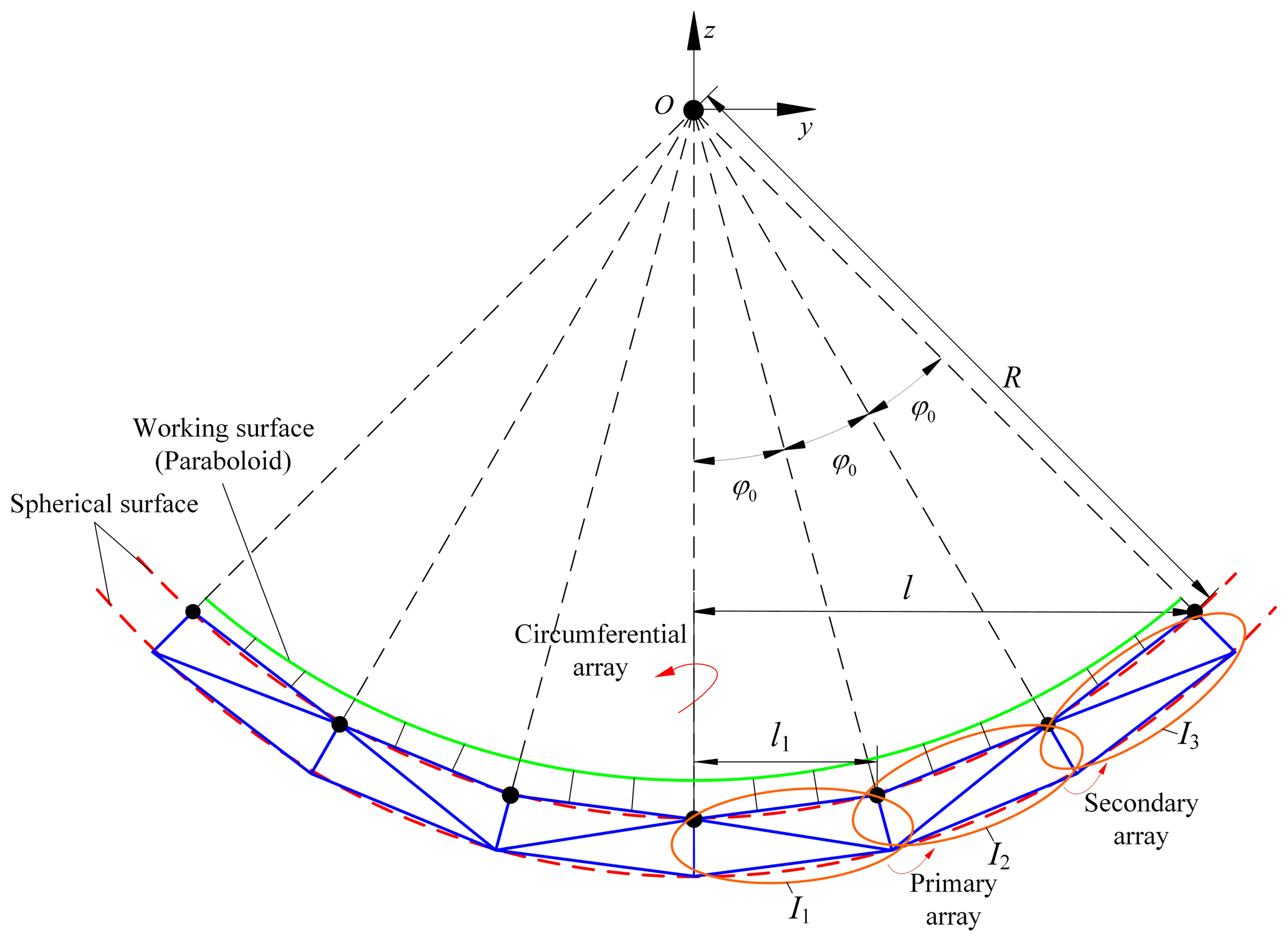
The mirror design method is used to design the three-fold mechanism. Taking the outer beam of sub-deployable unit I1 as the symmetry axis, sub-deployable unit I2 can be obtained by an array, and then sub-deployable unit I3 can be obtained by using the same method. Finally, the formed rib units () are arrayed circumferentially around the z axis as a whole to form a single-module unit. Given that the center angles φ0 corresponding to I1,I2,, and I3 are equal, the following can be obtained:
Considering the symmetry of the three-fold mechanism, in the following calculation, unit I1 is taken as an example to calculate the parameters, enlarge the position of I1, and establish a new coordinate system {O′} according to the right-hand rule. Coordinate origin O′ is located at the lower-end point of the central beam, the z axis direction is from O′ to A, and the y axis direction is from O′ to G, as shown in Fig. 7. Figure 7a shows the fully deployed state of I1, and Fig. 7b shows the fully folded state of I1. In Fig. 7a, φ1 is the angle between the outer beam DE and the z axis, φ2 is the angle between the lower beam GF and the y axis, φ3 is the angle between the diagonal beam and the y axis, and φ4 is the angle between the support beam KJ and the z axis. In Fig. 7b, φ5, φ6, and φ7 are the angles between the support beam, the large diagonal beam, and the small diagonal beam and the z axis, respectively.

Figure 7Schematic diagram of a parameter calculation model. (a) Fully deployed. (b) Fully folded.
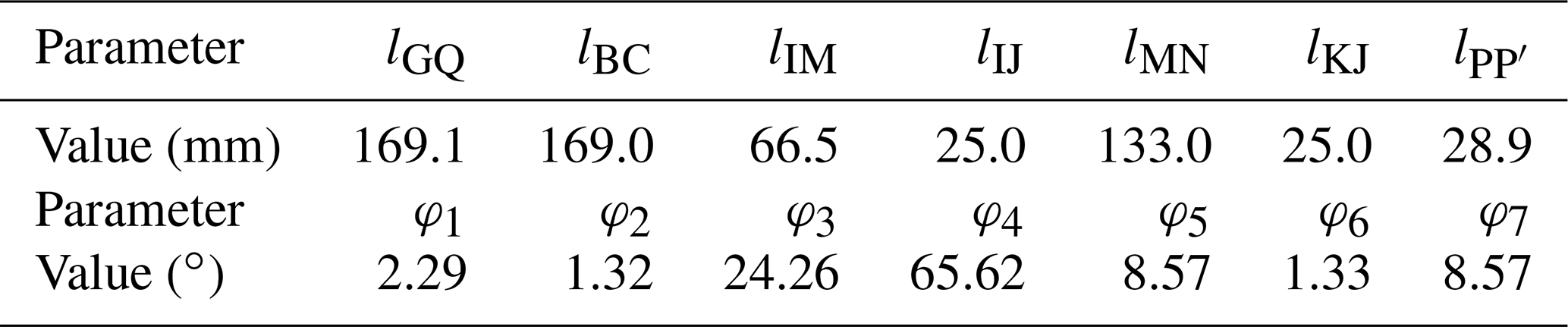
A trial algorithm is used to solve the specific parameters, among which the unknown beams mainly include outside beams BC and GQ, and inner beams IM, MN, and KJ. First, the initial value of the length of the other beams is given in advance, and the equations are solved according to the two limit states and the positional relationship between beams. If the equations have no solution, then the initial value is modified and the equations are solved again.
3.1.1 Size calculation of outside beam
After the supporting mechanism is fully deployed, the upper and lower endpoints O′, A, D, and E of central beam O′A and outer beam DE are all on the spherical surfaces of their fitting balls. A point S on beam CD is used to ensure because the length of the central beam , lEQ and are known, and the coordinates of point Q can be expressed as follows:
The length of the lower beam GQ can be obtained as follows:
Given that the coordinates of point Q have been obtained, lCD is known, and lQS=lDE, the coordinates of point C are given by the following:
lAB is known in the design; thus, the length of the upper beam BC is as follows:
3.1.2 Size calculation of the inner beam
The lower beam GQ is a component with three rotating pairs, and the coordinates of point F are given by the following:
where .
According to the relationship between the two limited positions of the rib unit and the length of each side in the right triangle, the following equations are obtained:
Equation (7) contains four unknowns, namely φ4, φ7, lIM, and lMN, and the number of unknowns is consistent with the number of equations. Thus, the lengths of small diagonal beam IM and large diagonal beam MN can be calculated.
Similar to the calculation of diagonal beam size, according to the relationship between the beams at the two limit positions of the rib unit, the following equations can be obtained:
Similarly, Eq. (8) contains four unknowns, namely φ3, φ5, lIJ, and lKJ. Thus, the length of the support beam KJ can be calculated, and the dimensions of each beam in the rib unit can be determined.
According to the design requirements, the proposed spherical radius R=5000, l=600 mm, and other given dimensions include lAB=10, , lCD=21, lEQ=5, and lAH=8 mm. After calculation, the dimensions and the key included angles of the outer and inner beams are shown in Table 1.
3.2 Calculation of included angle of rib unit
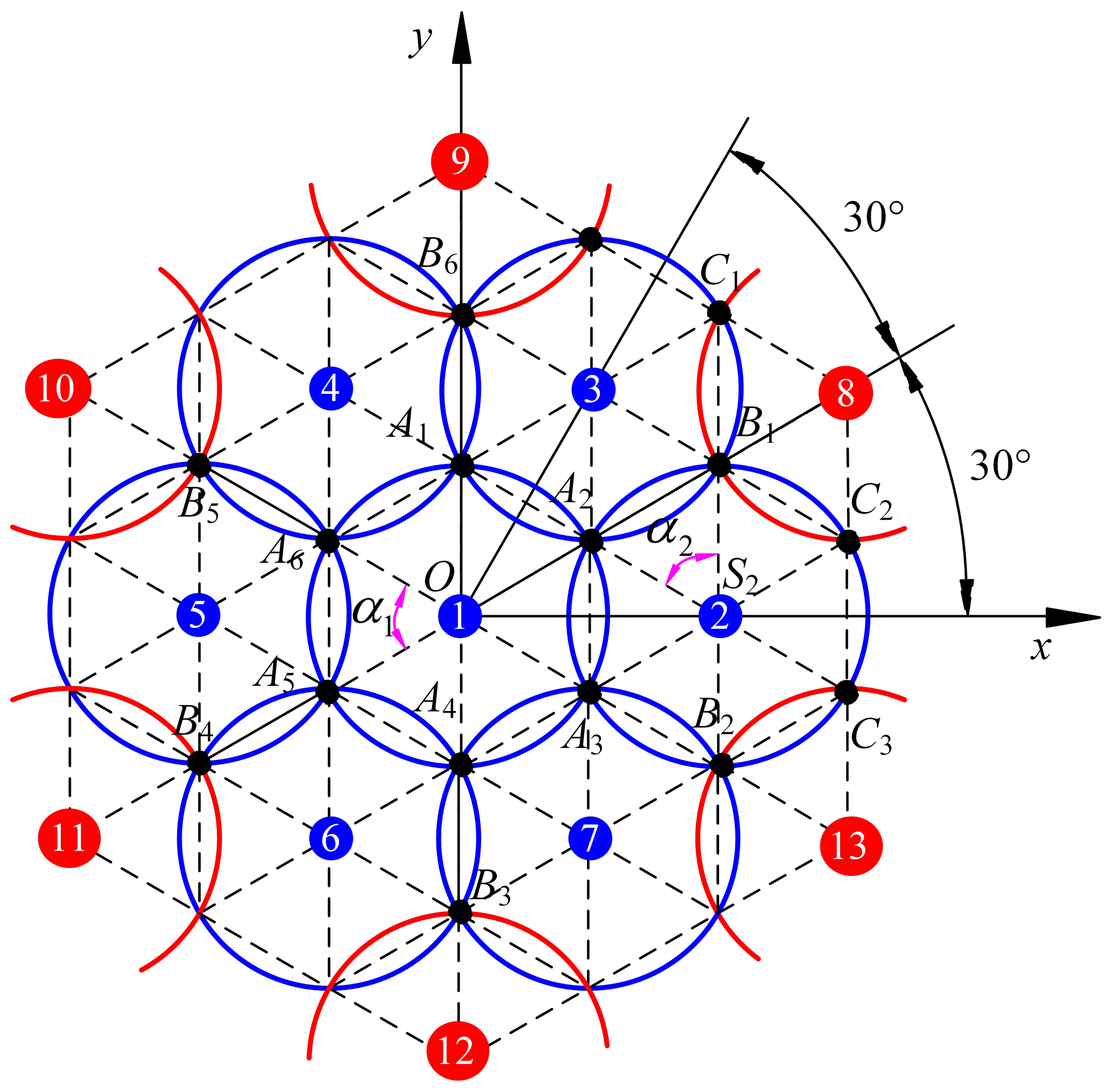
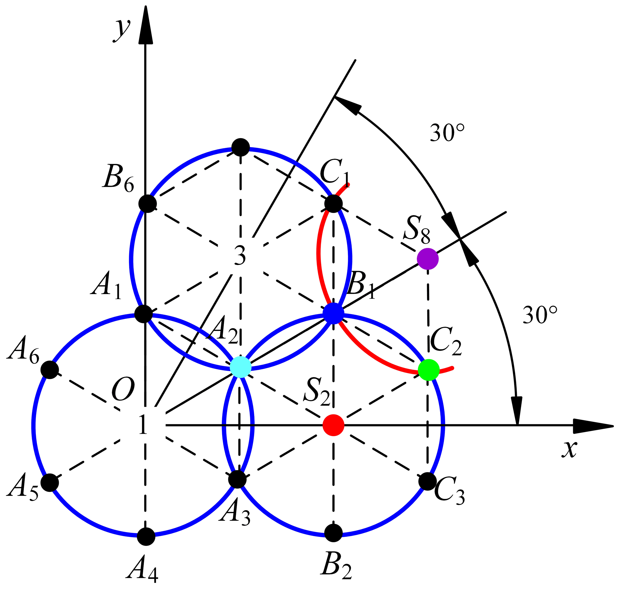
To ensure that the connection points of each module are laid on a spherical surface accurately, the positions of the key points of the deployable mechanism must be determined because the surface of the deployable antenna mechanism is a fitting spherical surface, and the included angles between the rib units are not equal. The basic dimensions of the rib units of each module are the same; that is, each module can be simplified as an envelope circle with an equal radius (Tian et al., 2021), a sphere with radius R can be constructed with several envelope circles with the same radius, a rectangular coordinate system can be established with the center O of the sphere as the coordinate origin, and a coordinate system {O} can be established according to the right-hand rule. The top view of the envelope circle with equal radius is shown in Fig. 8. Envelope circle 1 located in the center is defined as the first envelope circle, and the second envelope circle and the third envelope circle can be regarded as being envelope circles 2 and 8, respectively, which are rotated by 60∘ around the z axis, and the centers of the envelope circles 3 and 8 are located on the included angle plane equal to 30∘.
The center of the envelope circle n is represented by Sn, n=1, 2, …, 13. Figure 9 shows the projection of the envelope circle 1 on the yoz plane. According to the geometric relationship in the figure, the coordinates of the envelope circle center S1 can be expressed as follows:
The coordinates of point A1 can be expressed as follows:
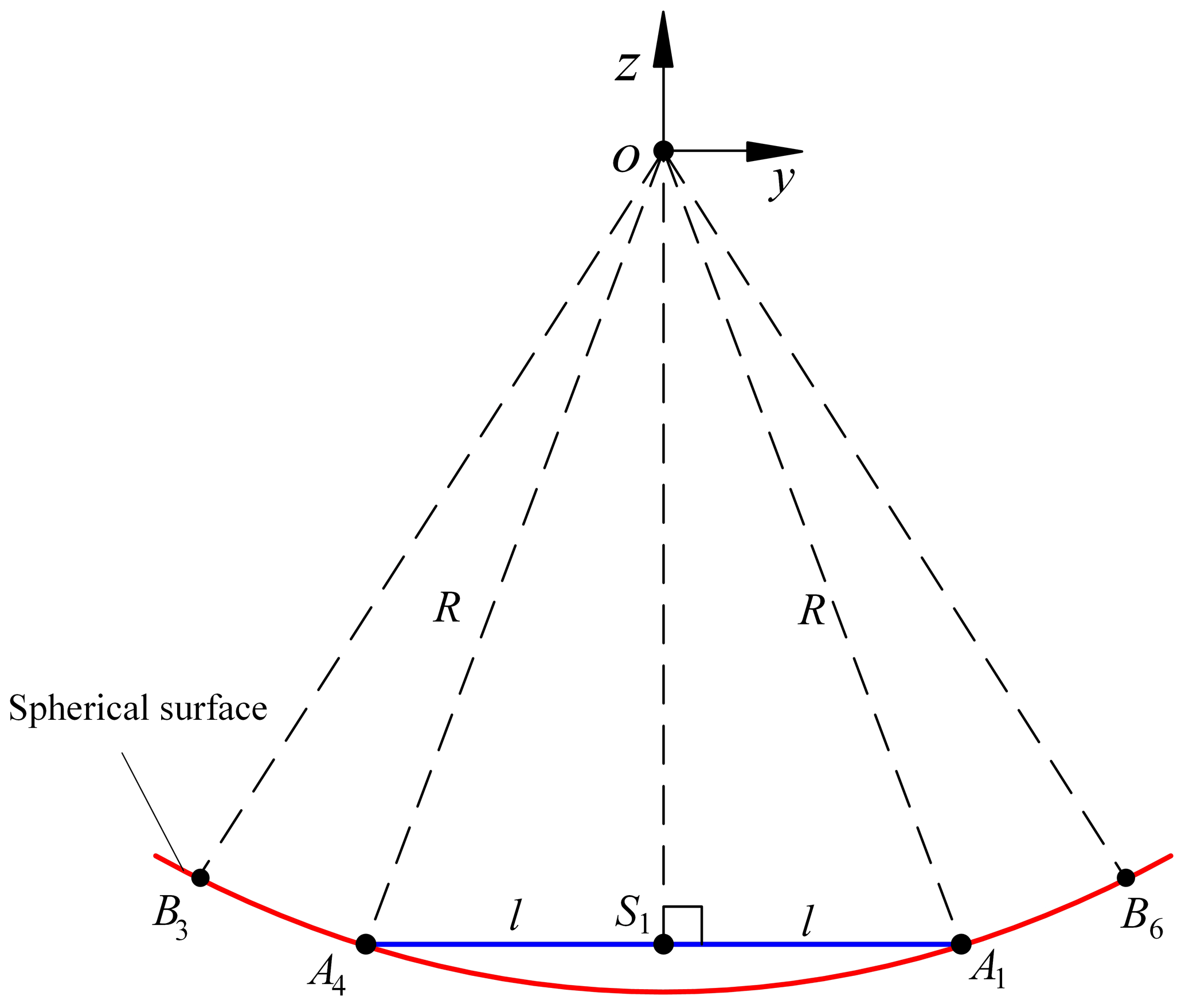
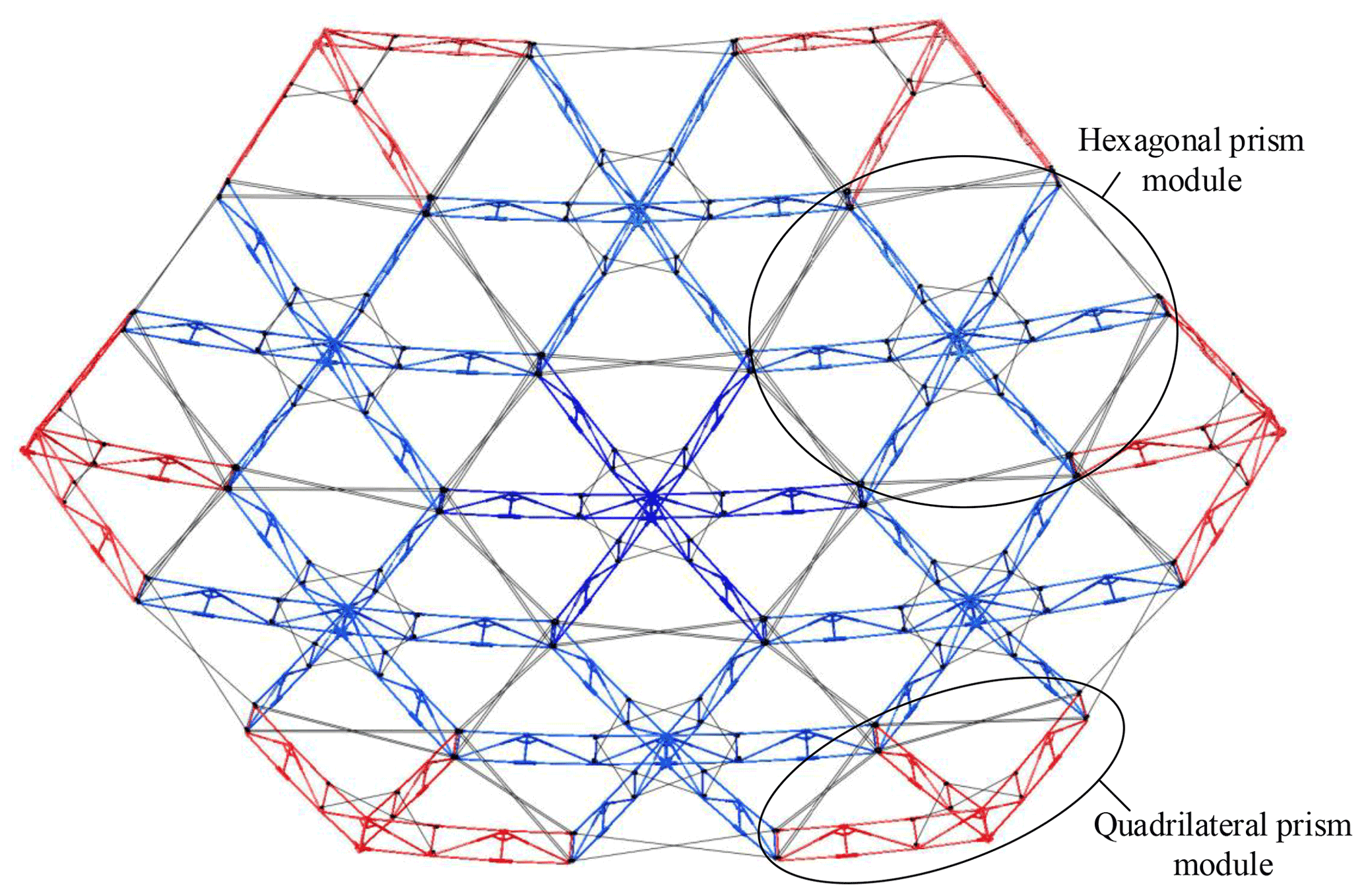
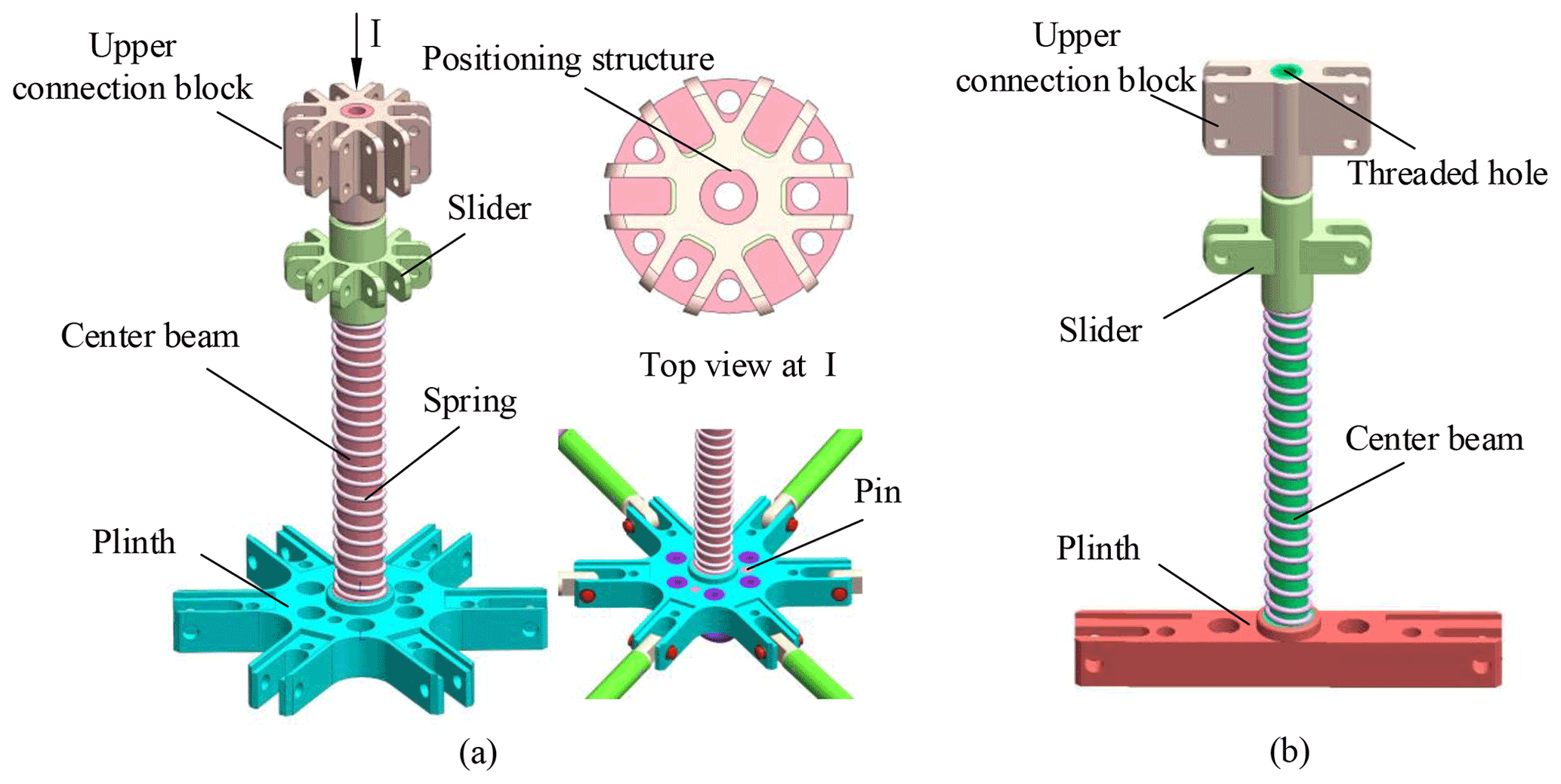
Figure 11Central beam assembly. (a) Hexagonal central beam assembly. (b) The two-fold and three-fold connection.
According to robotics theory (Cai and Xie, 2015), the coordinates of A2−A6 in the coordinate system can be obtained according to the following rotation transformation:
where
The center S3 of envelope circle 3 satisfies the following equation:
Given that S2 and S3 are on the same envelope circle, the coordinates of S3 are further obtained as follows:
where
Then, the equations of envelope circles S2 and S3 in the coordinate system are as follows:
By solving Eqs. (16) and (17), the coordinates of point B1 in the coordinate system can be obtained, and the coordinates of B2–B6 are described as follows:
Figure 8 shows that, taking the angle α2 as an example, the adjustment angle of the second layer module for accurate connection is explained. From the coordinates of A2 and B1 in the coordinate system, the distance can be calculated, and then adjustment angle α2 can be obtained as follows:
Given that the outside of ∠C2S2C3 is not connected to other modules, this angle can be regarded as an adjustable angle; that is, on the basis of meeting the precise connection between S2 and S8, the angle can be modified and adjusted appropriately, and the included angle between other modules can be adjusted by the method above after calculation.
Based on the above structure scheme and parameter calculation, a detailed structural design is carried out. Figure 10 shows the 3D model of the deployable antenna support truss. After the mechanism is deployed, the whole is in the shape of a hexagonal prism, and the modules can be accurately connected.
The whole structure is close to a spherical space, which indicates that the support mechanism meets the expected requirements in structural design and verifies the rationality of the previous design and the correctness of the parameter analysis. In the structure design of the support mechanism, the central beam assembly, the diagonal beam assembly, and the outer beam assembly face three design difficulties. The main reasons are as follows:
-
The center beam assembly is the most complex and functional component in the module. On the one hand, it is used as a frame to connect the upper and lower beams, the support beam, and the small diagonal beam to complete the linking of the whole mechanism. On the other hand, it is used as the carrier of the spring and the slider to drive the whole structure unit.
-
The diagonal beam assembly is located inside the mechanism. After the mechanism is folded, the angle between the large diagonal beam and the small diagonal beam is extremely small, which is likely to interfere. Moreover, the storage rate of the mechanism affects the design of the mechanism. Thus, the circular beam may no longer be applicable.
-
The outer beam assembly is located at the connection between modules, which affects not only the deploying stability of the structure but also the overall stiffness of the structure. The structural form of the outer beam assembly also influences the installation efficiency of the structure.
Therefore, this paper mainly introduces the structure design of these three key components.
4.1 Design of the central beam assembly
The design of the central beam assembly is mainly divided into three parts, namely the hexagonal central beam assembly, quadrangular prism central beam assembly, and two-fold and three-fold connection. Figure 11a shows that it is a hexagonal prism central beam assembly, which is mainly composed of upper connecting block, center beam, and plinth. The upper connecting block is similar to the plinth in structure and is petal shaped. The two parts are connected by a central beam, which is used to connect the upper beam and the lower beam of the rib unit. The upper part of the plinth is provided with a small convex structure that is matched with the spring, and the lower part of the plinth adopts a hollow structure to reduce the structural quality. A threaded hole is reserved in the center of the beam to facilitate later installation of the reflective mesh surface. A positioning structure is designed at the connection between the upper connecting block and the central beam, and a pin is arranged at the connection between the central beam and the plinth. By the positioning structure and the pin, this ensures that the outer connecting ports of the connecting block and the plinth are in the same plane, and the included angle between the rib units is ensured. The positioning of other parts adopts the shaft shoulder positioning method. The design of the center beam of the quadrangular prism is the same as that of the hexagonal prism and will not be repeated here.
Figure 11b shows the two-fold and three-fold connection. Given only the left and right units, a scaled structure similar to the hexagonal central beam assembly is used to reduce the outer diameter of the central beam and the structural quality. The plinth adopts a hollow structure similar to a cuboid, which is matched with the central beam to ensure the axial positioning of the plinth and the central beam. The upper part of the center beam is still designed with a positioning structure, and the upper part is reserved for threaded holes, which is convenient for the later installation of the reflective mesh.
4.2 Design of the diagonal beam assembly
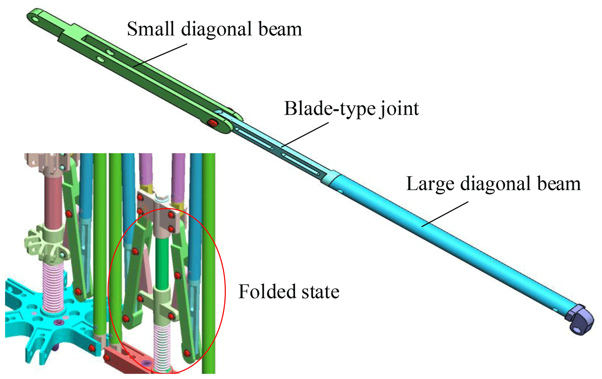
Figure 12 shows that the diagonal beam mainly includes the large diagonal beam and the small diagonal beam. One end of the small diagonal beam is connected to the upper connecting block, the middle of the diagonal beam is hinged with the support beam, and the other end is rotationally connected to the large diagonal beam. One side of the large diagonal beam is connected to the lower beam by a joint, and the other side is hinged to the small diagonal beam. The whole small diagonal beam is hollowed out, and one side of the large diagonal beam is designed as a thin joint in the shape of a blade. When the mechanism is folded, the blade-type joint is embedded into the hollow of the small diagonal beam to minimize the folded volume and increase the structural storage rate. A stop block is added at the right connection of the small diagonal beam. When the mechanism is fully deployed, the large diagonal beam and the small diagonal beam are in the same straight line by the action of the stop block.
4.3 Design of the outer beam assembly
Figure 13 shows the outer beam assembly. After observation, at most three rib units are linked at the connection between the modules, and the angle of the connection between modules is 120∘, according to the included angle between the rib units. Moreover, concave and convex grooves are designed at the outer connection of the upper joint, and the precise connection between modules is realized by these grooves. The outer sides of the upper and lower joints are fixed by bolts to improve the connection stability and the convenience of structure assembly and replacement further. Screw holes are reserved at the top of the upper joint to facilitate later installation of the reflective mesh surface. A hole is in the upper joint and the lower joint to facilitate the later installation of tension cable.
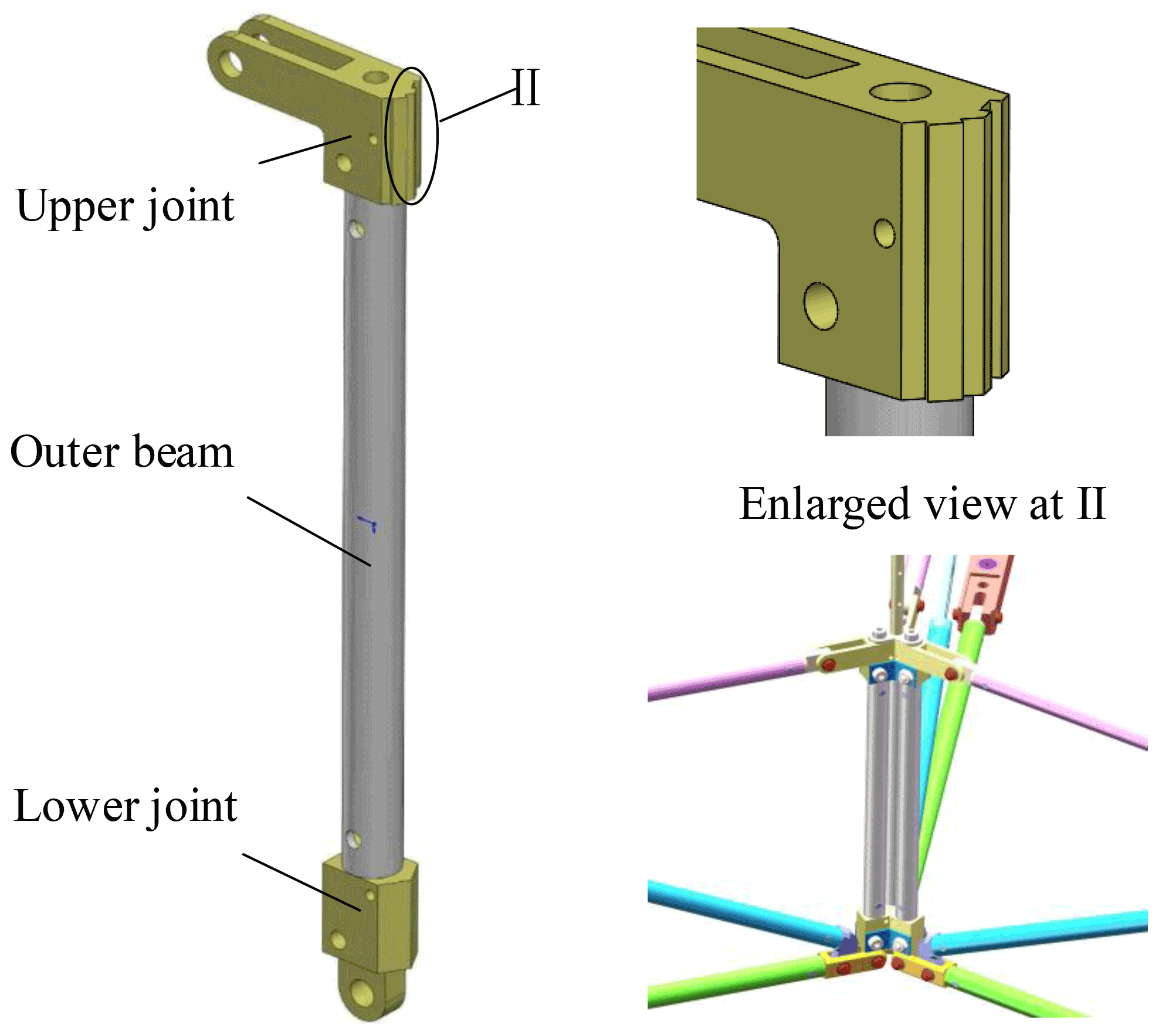

Figure 14Deployment simulation of deployable antenna mechanism, where (a) t=0 s, (b) t=15 s, (c) t=40 s, and (d) t=100 s.
5.1 Multimodule kinematic simulation
To further verify the rationality of the design scheme of the deployable antenna mechanism established above, the established 3D model is imported into ADAMS software, and the kinematics analysis module in the software is used to simulate the structure. Owing to the complexity of the whole antenna structure model, which involves many connecting members and hinges, if the pre-established model is used for simulation analysis, then the process will be long and complicated. Thus, the model is simplified before simulation, and the processing principles are as follows:
-
The connecting parts such as pins and bolts are ignored.
-
The connection of each component is in an ideal state, with no friction and collision.
-
Binding constraints are used between parts without relative motion.
According to the parameters in Table 1, the stroke PP' of the slider can be obtained as 28.9 mm. In software, driving forces and constraints are imposed on the components of the mechanism. The slider is set to move at a constant speed with 100 s simulation time, and the driving function is 0.289 mm s−1.
The deployment state of the antenna mechanism at t=0, t=15, t=40, and t=100 s is selected, and then the deployment of the deployable antenna mechanism can be obtained through simulation, as shown in Fig. 14.
Figure 14 shows that when t=0 s, then the antenna supporting mechanism is completely folded, which is consistent with the expected result. At t=15 and t=40 s, the antenna support mechanism is in deployment, the module can still be connected accurately during deployment, and the motion state is normal. When t=100 s, the antenna support mechanism is fully deployed. Therefore, the deployable antenna support mechanism composed of 13 modules can realize simultaneous, synchronous deployment under the condition of ensuring an accurate connection.
5.2 Multimodule kinematic analysis
To grasp the motion law of the deployable antenna support mechanism better, the following key points are selected for analysis. The above analysis shows that modules 1–13 are formed by typical modules 1, 2, and 8 through an array. According to this rule, five points, A2, B1, C2, S2, and S8, are selected. Figure 15 shows that, first, the three points A2, B1, and C2 summarize the connection points between modules; second, the two points S2 and S8 are the center points of the typical module 2 of the second layer and the typical module 8 of the third layer, respectively, and S8 is the farthest boundary point of the whole deployable antenna support structure. Therefore, these five points cover all the representative key points on the antenna support mechanism, and the motion law of these five points can reflect the motion law of the whole antenna support mechanism. Based on the above multimodule linkage simulation, the distance s from the above key points to the center of the module is selected as the dependent variable, and the time t is the independent variable. Thus, the functional relationship curves of displacement, velocity, and acceleration of the above five points with t can be obtained through kinematic analysis, as shown in Figs. 16, 17, and 18, respectively.
An analysis of the data in the above figures reveals the following:
-
Figure 16 shows that the antenna support mechanism has completed most of the displacement within 0–40 s, and the antenna mechanism is almost fully deployed. The displacement of each point changes slowly after 40 s. This change rule is consistent with the overall movement trend in Fig. 14. The displacement curve of S8 shows that the deployment maximum radius of the multimodule deployment is 1827.9 mm, and the folded radius is 315.6 mm. Hence, the deployment maximum diameter of the antenna structure is 3655.8 mm.
-
Figure 17 shows that the deployment speed of the antenna support mechanism has been increasing within 0–5 s and reaches the maximum value at 5 s. In 5–40 s, the deployment speed gradually decreases. After 40 s, the curve becomes flat, and the deploying speed gradually approaches 0. The whole time history shows that the deploying action of the antenna mechanism is mainly concentrated in the time period of 0–40 s, and the mechanism completes most of the deploying action in 40 % of the time, which is consistent with the curve of Fig. 16.
-
Figure 18 shows the acceleration curve. In 0–8 s, the deployment acceleration of the antenna support mechanism rapidly decreases from the maximum to the minimum. Within 8–40 s, the absolute value of the deployment acceleration gradually decreases. After 40 s, the deployment acceleration gradually approaches 0. When t=5 s, the acceleration is 0, which is consistent with the position of the inflection point in the velocity curve. In addition, a large acceleration remains in the interval of 0–40 s, and the changes in the displacement and velocity curves in the corresponding Figs. 16 and 17 are apparent. The curves in Figs. 16–18 can be mutually verified, which indicates that the analysis is correct.
-
Further analysis of Figs. 16–18 shows that the motion law curves of each figure are in a smooth state, and the motion trends of each point in each group of curves are the same, which shows that the overall deployment of the support mechanism is smooth and synchronous.
The changes in these curves show that the proposed modular deployable antenna support mechanism can complete the deployment action well, and the deployment action is smooth and has good synchronization. When the slider is driven at a constant speed, the multimodule synchronous deployment is nonuniform. During the deployment of the antenna support mechanism, the deployment of the mechanism within the first 40 s has almost completed most of the whole process. This research work has a high reference value for future research on the driving law of an antenna mechanism and the dynamic analysis of the deployment.
The multifold rib deployable antenna structure designed above is developed by 3D printing technology. According to the size of each beam in the calculation of the rib unit parameters, a prototype of the hexagonal prism single module with a deployment aperture of 1.2 m is developed. The antenna beam is made of a carbon fiber tube, the center beam and hinges are made of nylon material, and the thin rope, made of Kevlar, is used as the tension cable. The structure is shown in Fig. 19. The deployment function test is carried out. Under the condition of gravity, the spring is manually moved up, and the prototype of the antenna structure can be smoothly deployed in place. Repeated deployment tests are carried out on the prototype, and the mechanism can still be deployed, which shows that the scheme and principle of the mechanism are feasible.
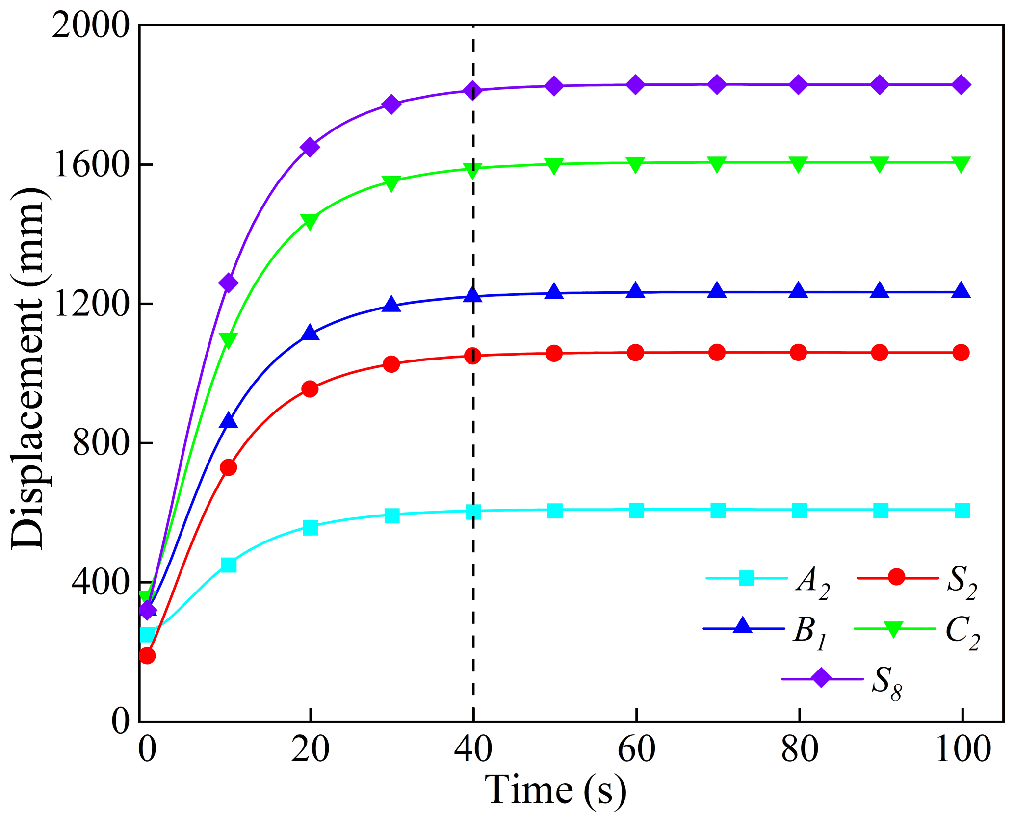
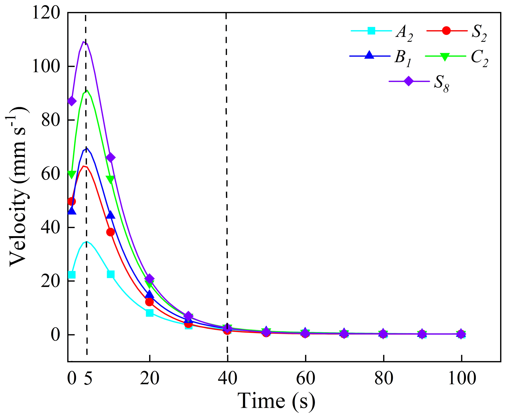
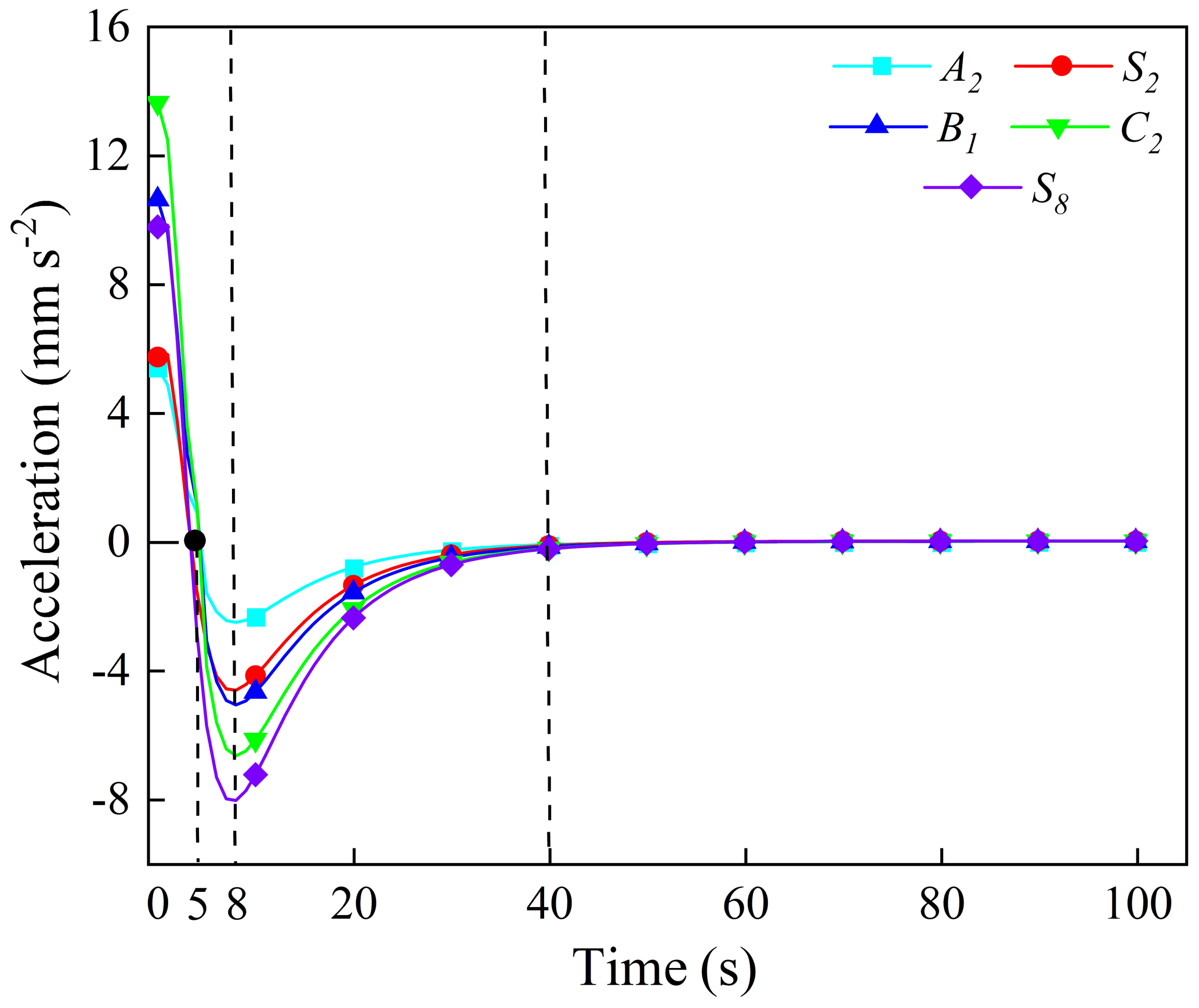
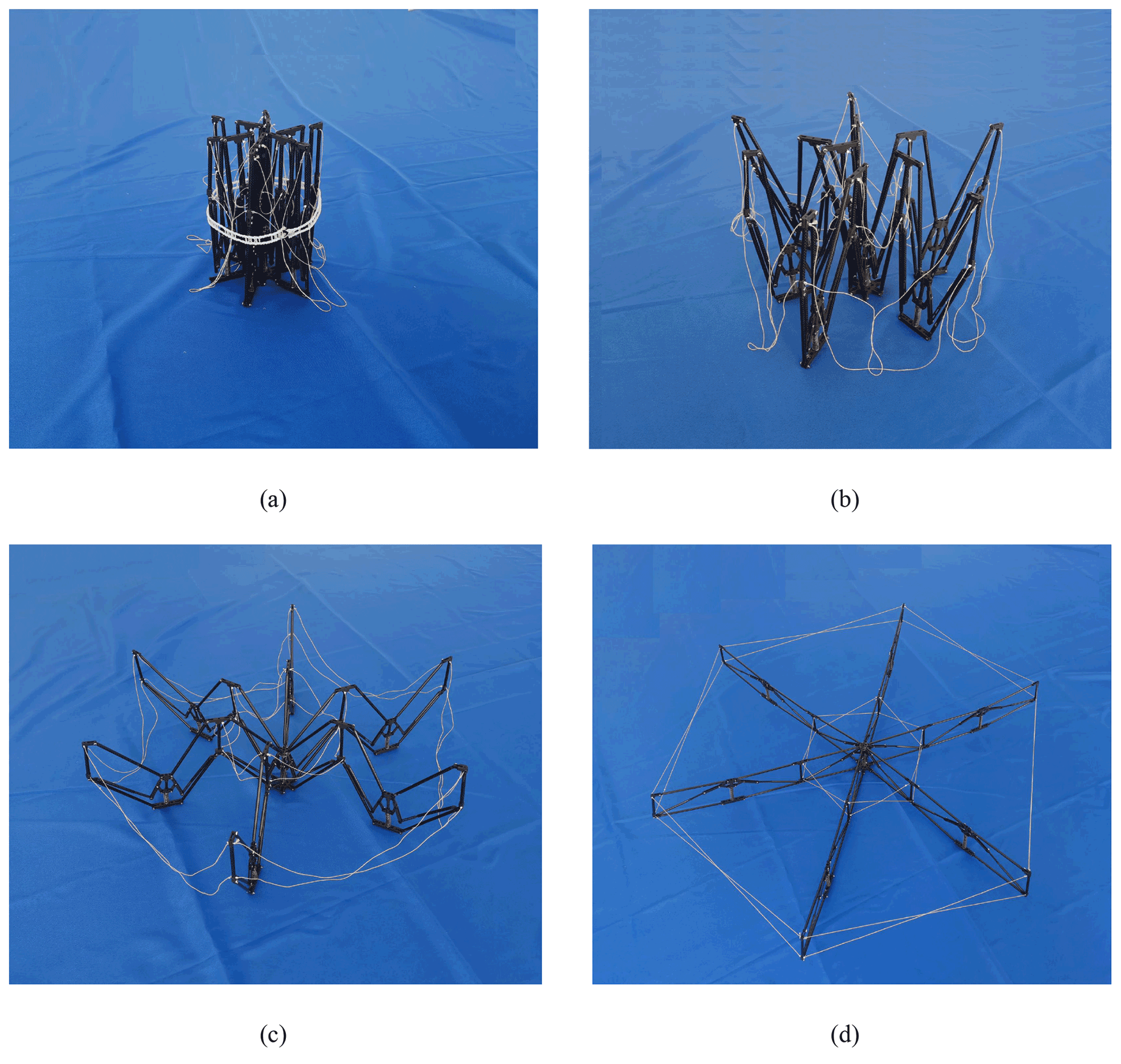
Figure 19Hexagonal single-module principle prototype. (a) Fully folded state. (b) Semi-deployed state 1. (c) Semi-deployed state 2. (d) Fully deployed state.
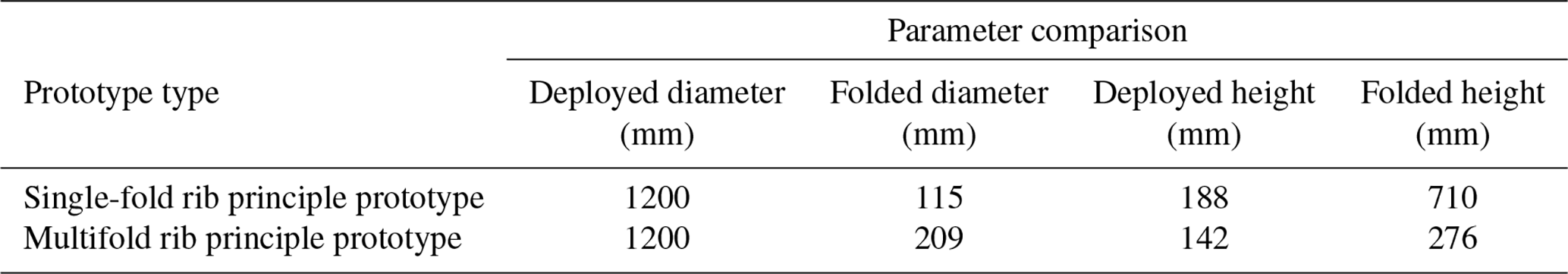
To verify the static technical index of the multifold rib deployable antenna proposed in this paper further, it is compared with the single-fold hexagonal prism module (Tian, 2011) previously studied by the research group. Both have the same aperture in the deployed state, but the materials are different. The single-fold rib antenna principle prototype beam and each hinge material are made of aluminum alloy, the center beam is made of carbon steel as the processing material, and the tension cable is made of steel cable. The two types of principle prototypes are tested and compared. Their deployment diameter, folded diameter, deployment height, and folded height are measured, and the parameters are shown in Table 2.
Storage rate (Tibert, 2002) is an important technical index of the deployable antenna. The general definition is the ratio of the volume of the deployable antenna in the folded state to the volume in the deployed state. In a modular deployable antenna, the storage rate can be understood as the ratio of the volume of the outer enveloping cylinder when the module is in the following two states:
where R1 and R2 is the radius of the bottom circle of the outer envelope cylinder in the folded and deployed states, respectively. H1 and H2 is the height of the outer envelope cylinder in the folded and deployed states, respectively.
Equation (20) shows that the smaller the value of the storage rate η, the larger the volume change of the antenna from folded to deployed state; that is, the antenna has a higher storage rate. Therefore, the storage rate of the single-fold rib antenna is approximately 0.035, and that of the multifold rib antenna is approximately 0.058. The support mechanism designed in this paper has a high storage rate, which is favorable for developing it into a larger aperture support mechanism.
In this paper, aiming at the urgent demand of the large-scale development of deployable antenna in the future, a new configuration of a mesh deployable antenna mechanism is proposed, and the structure scheme design, parameter calculation, structure design, kinematic simulation analysis, and experimental verification are carried out. The main conclusions are as follows:
-
Taking the sub-deployable unit as the minimum deployable mechanism unit and obtaining the module unit and multimodule support mechanism by arraying it are feasible. The proposed innovative design scheme of multifold rib modular deployable antenna mechanism realizes the combination change of the quadrangular prism module and the hexagonal prism module, which has good structural expansibility and has the potential to develop into a large-aperture antenna.
-
The structural parameters are determined by theory of geometric model and robotics, and the mechanism is designed in detail. Moreover, the kinematic simulation model of the mechanism is established by numerical simulation software, which verifies the correctness of the mechanism principle and motion law.
-
The developed principle prototype is unfolded gently and smoothly and can be locked in place smoothly after deploying, which shows that the supporting mechanism is correct in the aspects of deployment principle, locking scheme, parameter calculation, structural design, and detailed design. The research results have great guiding importance and reference value for the research and engineering application of other configurations of mesh deployable antenna.
-
The proposed multifold rib modular deployable antenna mechanism can adapt to the future development trend of ultra-large deployable antennas by further changing the module size, number, and connection method. In the future, more in-depth research will be carried out on the dynamic characteristics, structural stiffness influence law, and surface accuracy of this configuration to provide technical support for accelerating this structure into practical engineering applications.
All data included in this study are available upon request to the corresponding author.
DT and RL proposed the idea of deployable antenna and developed the structure scheme. HG and JX contributed to the establishment of the 3D model and kinematic analysis. CS and YZ contributed to the simulation analysis and prepared the figures. DT, HG, and LJ wrote and edited the paper.
The contact author has declared that neither they nor their co-authors have any competing interests.
Publisher's note: Copernicus Publications remains neutral with regard to jurisdictional claims in published maps and institutional affiliations.
The authors would like to thank reviewers, for their valuable comments and suggestions that enabled us to revise the paper.
This research has been supported by Key Program of National Natural Science Foundation of China (grant no. 51835002), the China Postdoctoral Science Foundation (grant nos. 2019M661126 and 2021M690827), the Heilongjiang Postdoctoral Fund (grant no. LBH-Z20135), and the Foundation of Liaoning Education Department (grant no. LJKZ0563).
This paper was edited by Guowu Wei and reviewed by Sanjin Troha and one anonymous referee.
Brown, T. S.: A GNC perspective of the launch and commissioning of NASA's SMAP (Soil Moisture Active Passive) spacecraft, 54th AIAA Aerospace Sciences Meeting, San Diego, California, 4–8 January 2016, https://doi.org/10.2514/6.2016-0479, 2016.
Cai, Z. X. and Xie, B.: Robotics, 3rd Edn., Beijing: Tsinghua University Press, http://www.tup.com.cn (last access: 5 December 2021), 2015.
Chandra, M., Kumar, S., Chattopadhyaya, S., Chatterjee, S., and Kumar, P.: A review on developments of deployable membrane-based reflector antennas, Adv. Space Res., 68, 3749–3764, https://doi.org/10.1016/j.asr.2021.06.051, 2021.
Chebotarev, A. S., Panteleev, V. A., Feyzulla, N. M., Mitrofanov, E. M., and Plastikov, A. N.: Truss-type deployable reflector antenna systems for synthetic aperture radar mounted on a small spacecraft, Crimean Conference “Microwave and Telecommunication Technology” (CriMiCo'Z014), Sevastopol, Crimea, Russia, 7–13 September, 1–2, https://doi.org/10.1109/crmico.2014.6959508, 2014.
Datashvili, L.: Foldability of hinged-rod systems applicable to deployable space structures, Ceas Space J., 5, 157–168, https://doi.org/10.1007/s12567-013-0052-7, 2013.
Eliseeva, A. Y., Komar, L. A., and Kondyurin, A . V.: Computational modeling of the curing of a frame of an inflatable satellite antenna in near-earth orbit, J. Appl. Mech. Tech. Ph.+, 62, 1234–1242, https://doi.org/10.7242/1999-6691/2020.13.4.32, 2022.
Fedorchuk, S. D. and Arkhipov, M. Y.: On the assurance of the design accuracy of the space radio telescope RadioAstron, Cosmic Res.+, 52, 379–381, https://doi.org/10.1134/S0010952514050049, 2014.
Guo, J. W., Zhao, Y. S., Xu, Y. D., and Zhang, G. X.: Mechanics analysis and structural design of a truss deployable antenna mechanism based on 3RR-3URU tetrahedral unit, Mech. Mach. Theory, 174, 104881, https://doi.org/10.1016/j.mechmachtheory.2022.104881, 2022.
Hanayama, E., Kuroda, S., Takano, T., Kobayashi, H., and Kawaguchi, N.: Characteristics of the large deployable antenna on HALCA satellite in orbit, IEEE T. Antenn. Propag., 52, 1777–1782, https://doi.org/10.1109/tap.2004.831281, 2004.
Huang, H., Guan, F. L., Pan, L. L., and Xu, Y.: Design and deploying study of a new petal-type deployable solid surface antenna, Acta Astronaut., 148, 99–110, https://doi.org/10.1016/j.actaastro.2018.04.042, 2018.
Krishnan, G., Kim, C., and Kota, S.: Building block method: a bottom-up modular synthesis methodology for distributed compliant mechanisms, Mech. Sci., 3, 15–23, https://doi.org/10.5194/ms-3-15-2012, 2012.
Li, P., Liu, C., Tian, Q., Hu, H. Y., and Song, Y. P.: Dynamics of a deployable mesh reflector of satellite antenna: form-finding and modal analysis, J. Comput. Nonlin. Dyn., 11, 10–17, https://doi.org/10.1115/1.4033440, 2016.
Liu, R., Guo, H., Liu, R., Wang, H., Tang, D., and Deng, Z.: Structural design and optimization of large cable-rib tension deployable antenna structure with dynamic constraint, Acta Astronaut., 151, 160–172, https://doi.org/10.1016/j.actaastro.2018.05.055, 2018.
Liu, R. Q., Shi, C., Guo, H. W., Li, B. Y., Tian, D. K., and Deng, Z. Q.: Review of space deployable antenna mechanisms, J. Mech. Eng., 56, 1–12, https://doi.org/10.3901/jme.2020.05.001, 2020.
Luo, Z., Shang, J., Wei, G., and Ren, L.: Module-based structure design of wheeled mobile robot, Mech. Sci., 9, 103–121, https://doi.org/10.5194/ms-9-103-2018, 2018.
Ma, X. F., Yang, J., Hu, J. F., Zhang, X., Xiao, Y., and Zhao, Z. H.: Deployment dynamical numerical simulation on large elliptical truss antenna, Sci. Sin.-Phys. Mech. Astron., 2, 147–155, https://doi.org/10.1360/SSPMA2018-00131, 2019.
Mehran, M., Steve, K., Chri,s S., and Eric, S.: Design and performance of Astromesh reflector onboard Soil Moisture Active Passive spacecraft, Aerosp. Conf. Proc., 3, 1–10, https://doi.org/10.1109/AERO.2012.6187094, 2012.
Morozov, E. V., Lopatin, A. V., and Khakhlenkova, A. A.: Finite-element modelling, analysis and design of anisogrid composite lattice spoke of an umbrella-type deployable reflector of space antenna, Compos. Struct., 286, 115323, https://doi.org/10.1016/j.compstruct.2022.115323, 2022.
Ozawa, S.: Research and development of 30m class large deployable reflector, Journal of the Society of Mechanical Engineers, 113, 442–443, https://doi.org/10.1299/jsmemag.113.1099_442, 2010.
Santiago, P. J. and Baier, H.: Advances in deployable structures and surfaces for large apertures in space, Ceas Space J., 5, 89–115, https://doi.org/10.1007/s12567-013-0048-3, 2013.
Semler, D., Tulintseff, A., Sorrell, R., and Marshburn, J.: Design, integration, and deployment of the TerreStar 18-meter reflector, 28th AIAA International Communications Satellite Systems Conference, Anaheim, Califomla, 30 August–2 September 2010, 8885–8867, https://doi.org/10.2514/6.2010-8855, 2010.
Shi, C., Guo, H. W., Li, M., Liu, R. Q., and Deng, Z. Q.: Conceptual configuration synthesis of line-foldable type quadrangular prismatic deployable unit based on graph theory, Mech. Mach. Theory, 121, 563–582, https://doi.org/10.1016/j.mechmachtheory.2017.11.010, 2018.
Tian, D. K.: Design and experimental research on truss structure for modular space deployable antenna, PhD thesis, Harbin Institute of Technology, https://doi.org/10.7666/d.D264092, 2011.
Tian, D. K., Liu, R. Q., Deng, Z. Q., and Guo, H. W.: Fitting method of working surface generatrix for deployable truss antennas, Journal of Harbin Engineering University, 31, 1240–1247, https://doi.org/10.3969/j.issn.1006-7043.2010.09.019, 2010.
Tian, D. K., Fan, X. D., Jin, L., Liu, R. Q., and Zhang, K.: Surface accuracy analysis for hexagonal prism modular deployable antenna, Optics and Precision Engineering, 29, 2855–2867, https://doi.org/10.37188/ope.20212912.2855, 2021.
Tibert, G.: Deployable tensegrity structures for space applications, PhD thesis, Royal Institute of Technology Department of Mechanices, http://www-civ.eng.cam.ac.uk/dsl/publications/TibertDocThesis.pdf (last access: 20 December 2021), 2002.
Tomoyuki, N., Takash,i K., Takashi, O., and Yoshiro, H.: Design and flight test results of robust attitude controller for the ETS-VIII spacecraft, Reprints of the 18th IFAC World Congress, Milano, Italy, 28 August–2 September, 5154–5159, https://doi.org/10.3182/20110828-6-it-1002.00794, 2011.
Yang, H., Guo, H. W., Y, Wang., Feng, J., and Tian, D.: Analytical solution of the peak bending moment of an M boom for membrane deployable structures, Int. J. Solids Struct., 206, 236–246, https://doi.org/10.1016/j.ijsolstr.2020.09.005, 2020.
Zhang, R. N. and Jiang, X. P.: System design and in-orbit verification of the HJ-1-C SAR satellite, Journal of Radars, 3, 249–255, 2014.
Zheng, S. K., Ji, Y. Z., Cui, Z. Y., Fang, Y. G., and Zhou, L. P.: Design and analysis of HJ-1-C satellite SAR antenna, Journal of Radars, 3, 266–273, 2014.