the Creative Commons Attribution 4.0 License.
the Creative Commons Attribution 4.0 License.
 | 20 May 2022
The three-point eccentric magnetorheological polishing technology for hard brittle alumina ceramics
Cheng Zheng
Xiaoyu Yan
Yongchao Xu
Shangchao Hung
This work presents the design of a pressurised three-point eccentric magnetorheological polishing (MRP) device, for alumina ceramics' hard and brittle characteristics, and a carrier disc magnetic field generator and a single closed-loop uniform magnetic field generator for a more uniform and increased magnetic field distribution. When compared with the traditional gap type, this device considerably enhances polishing efficiency. This apparatus has also been used to explore the mechanism of MRP. Static magnetic field simulations were conducted, and the fundamentals of the three-point eccentric magnetorheological process were addressed. Alumina ceramics were polished with a three-point eccentric wheel MRP equipment. Polishing tests were conducted to explore the effects of rotational speed, working pressure, abrasive type, abrasive particle size and polishing duration on polishing properties, and optimised polishing parameters were established. The surface roughness (Ra) of the samples was dramatically reduced from 500 to 22.41 nm using the three-point eccentric MRP device. The pit markings on the alumina ceramics' surface vanished after polishing. Therefore, the approach has considerable polishing potential for hard and brittle materials that can be nanofabricated with minimal surface sub-damage.
- Article
(8663 KB) - Full-text XML
- BibTeX
- EndNote


With the development of multifunctional electronic ceramic components, alumina ceramics are being increasingly widely used in the electronic ceramics, precision instruments, optics, aerospace and military industries (Fan et al., 2019; Davim et al., 2008). Meanwhile, the requirements for surface precision and subsurface damage of alumina ceramics are also increasing. Alumina ceramics first undergo moulding and then the polishing process to improve surface precision machining and reduce surface residual stress (Vila-Nova et al., 2020; Fan et al., 2021; Xia et al., 2020). To handle the hardness and brittleness of alumina ceramics, magnetorheological polishing (MRP) is suggested as an alternative to the traditional polishing method. MRP is a flexible polishing method with high precision and causes little subsurface damage (Luo et al., 2018). Under the action of the magnetic field, the MRP fluid forms a polishing ribbon along the direction of the magnetic induction line to grind a workpiece surface. On the basis of the rheological properties of magnetorheological fluid, magnetorheological flexible polishing of alumina ceramics was realised (Y. Wang et al., 2020). In recent years, many scholars have studied MRP from different aspects of MRP theory and process. In terms of MRP theory, Wang et al. (2021) studied MRP on the basis of the reciprocating MRP principle and the Preston equation, and they established the material removal rate model of reciprocating MRP and its normal polishing pressure model. Guo et al. (2021) studied the continuity equation and Vand viscosity equation of suspension, and they established and calculated the modified cavitation bubble dynamics model, which provided a theoretical basis for exploring the ultrasonic cavitation effect of magnetorheological fluid in industrial applications. Chen et al. (2017) established the material removal function model of the MRP process on the basis of the three-dimensional hydrodynamic analysis of MRP and the Preston equation. The theoretical part of MRP is mainly based on the Vand equation and the Preston equation to modify the viscosity model and the removal rate model. In the aspect of MRP technology, Xu et al. (2021) designed a processing equipment of oblique axis ultra-precision grinding and MRP. After composite processing technology was used, the surface roughness (Ra) of a tungsten alloy aspheric mould reached 1 nm. Song et al. (2018) developed a new type of drum MRP device and studied its MRP mechanism. The surface roughness (Ra) of the polished sample was reduced from 359 to 38 nm. Nie et al. (2019) studied the influence of different magnet layouts on the MRP and conducted an experimental simulation of the influence of different magnet distribution on the polishing effect. C. Wang et al. (2020) proposed a new magnetic field-assisted mass polishing technology for multiple free-form components, which rotated the magnetic field applied outside the annular cavity to effectively polish the free-form surface workpiece. In studying the MRP process, polishing experiments are conducted on factors such as the polishing device, magnetic field generator, polishing path and process parameters. Then, the influence on the surface quality and removal efficiency of workpiece polishing is analysed. MRP is a two-surface shearing magnetic liquid–solid flow behaviour that requires installation accuracy, surface structure of the polishing pad and proper surface separation. In common third-body polishing processes, the removal of the workpiece material is induced by the contact between surfaces and hard particles (Yan et al., 2022). However, in MRP, the finishing effect is mainly caused by the quasi-solid characteristic of the flow under a magnetic field. Therefore, appropriate pressure should be used to ensure the effective material removal efficiency (Singh and Singh, 2021) and at the same time to prevent excessive friction caused by a large contact ratio (Xie et al., 2021), resulting in surface damage of the workpiece. The gap MRP efficiency is low due to the high hardness of alumina ceramic materials. The pressure MRP method is used to ensure the material removal efficiency. In addition, unlike with traditional polishing, the three-point eccentric MRP of the carrier plate and the magnetic plate rotates in opposite directions, thus being conducive to the replacement of abrasive particles in MRP fluid. The centreline of the object plate and the centreline of the magnetic pole plate are not on the same centreline, and a relative deflection angle exists, which reduces the polishing quality of the alumina ceramic substrate by the linear velocity difference. The MRP fluid distribution inside and outside the polished workpiece surface is more uniform, avoiding the influence of the rotation of the carrier disc.
In accordance with the characteristics of alumina ceramics, a multi-station three-point eccentric MRP method was proposed. The carrier disc and the disc rotate in opposite directions, and the centreline is not on the same centreline, setting a relative angle. In total, three workpieces are polished at the same time, and the workpiece is fixed on the 120∘ boundary line of the loading plate by using composite paraffin. The distance between the workpiece and the edge of the loading plate is 8 mm. The loading plate drives the alumina ceramic substrate to rotate counter clockwise. The MRP structure is a multi-body dynamic structure with fluid friction (Xie et al., 2022). The levelness of the disc was adjusted to below 1.25:1000 after the installation of the magnetic pole to prevent the flow-induced vibration of the pad–workpiece rotating disc structure. The drive disc drives the magnetic disc to rotate clockwise. The MRP fluid was affected by the magnetic field force, and it rotated clockwise with the magnetic disc. The alumina ceramic substrate was immersed in the MRP solution by using the loading plate. The MRP solution was subjected to magnetic force and changed from Newtonian fluid to Bingham to form a flux linkage brush, which was rotated and scratched opposite to the alumina ceramic substrate to achieve the surface removal effect of alumina ceramic substrate.
In this paper, a Unipol-1200S polishing machine was utilised as the carrier, with the use of a three-point eccentric MRP and a single closed-loop magnetic field alignment magnetic field launcher. The carrier plate was made of non-magnetic 316 L material to avoid interference with the magnetic field generator. The diameter was 160 mm, and the thickness was 15 mm. The processed sample was a 20 mm × 20 mm × 2 mm alumina ceramic substrate. As shown in Fig. 1, the three-point eccentric MRP could polish three workpieces in a group. The positive pressure was applied downward from the axis connected by the carrier disc, and the force position acted on the centre. The force of the three-point eccentric MRP workpiece was more uniform, and the horizontal balance of the carrier disc was effectively maintained. The magnetic field generator consists of the following three modules: the magnetic pad, the magnetic disc and the magnetic pole. The magnetic pad adopts metal magnetic conductive material, the magnetic disc adopts PVC plastic, and the magnetic pole is a permanent magnet material. The relative position of the magnetic pole is fixed by the magnetic pole disc, and the magnetic pole is arranged in accordance with the design method to achieve the effect of magnetic circuit closure (Heng et al., 2020; Zhao et al., 2021). The magnetic pole is fixed inside the disc by the magnetic pole pad, and the magnetic poles on both sides are fixed on both sides of the disc by magnetic force. The polishing disc of Unipol-1200S polishing machine is a magnetic-conducting metal material, and the magnetic field emission device is fixed on the drive disc of Unipol-1200S polishing machine by magnetic force. The magnetic force of the magnetic pole is large, which meets the working condition demand of the centrifugal force of the polishing machine. A small cluster arrangement gap corresponds to a more closed the magnetic circuit and thus greater magnetic field intensity. In accordance with the principle of Halbach, the following three kinds of closed-loop magnetic field arrangement were designed: full closed-loop, single closed-loop uniform and single closed-loop different magnetic field arrangements.

Figure 1Principle diagram and working condition diagram of the three-point eccentric MRP device.
N represents the magnetic pole N, S represents the magnetic pole S, and the blue arrow represents the direction from S to N, as shown in Fig. 2. When the gap in the magnetic pole arrangement is 0 mm, three different arrangement modes and magnetic field distribution could be found, i.e. full closed-loop, single closed-loop uniform and single closed-loop different magnetic field arrangements. The full closed-loop magnetic field arrangement requires a magnetic pole space to achieve a full closed-loop magnetic field. A total of four magnetic poles are a magnetic field distribution law. The negative 45∘ diagonal magnetic pole has a circular zero magnetic field area. The magnetic field strength is weak (0.2–0.3 T), and the magnetic field strength distribution is uneven. The magnetic field strength of the positive 45∘ diagonal magnetic pole is 0.3–0.4 T, and the magnetic field strength around the magnetic pole is 0.5–0.6 T. The magnetic field intensity of the single closed-loop magnetic field arrangement is alternately distributed. The strong magnetic field intensity has a partial zero gap at the magnetic pole gap. The strong magnetic field intensity band is 0.7–0.8 T, accounting for half of the total area, and the weak magnetic field intensity band is 0.2–0.4 T. The single closed-loop magnetic field is arranged, and the four magnetic poles are a magnetic field distribution law. The negative 45∘ diagonal magnetic pole has a weak magnetic field intensity of 0.0–0.25 T, and the magnetic field intensity distribution is uneven. The positive 45∘ diagonal magnetic pole magnetic field is 0.2–0.4 T, the highest magnetic field intensity is 0.6–0.7 T, and the lowest magnetic field intensity is 0.1 T. On the basis of the simulation results, the magnetic pole single closed-loop uniform magnetic field arrangement was selected; the high magnetic field intensity distribution area was large. Finally, the fixed point was measured by using a Tesla meter; the measurement results were basically consistent.

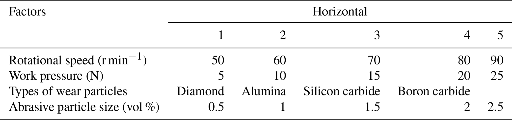
In this paper, alumina ceramic substrate was used as the polishing object (Yang et al., 2019). The surface of the alumina ceramic substrate is rough before polishing, with many pits on the surface, as shown microscopically. The MRP solution was composed of 40 vol % iron powder, the magnetic pole was arranged in a single closed-loop uniform magnetic field, and the rotational speed of the loading plate was 60 r min−1 (Fig. 3). The initial roughness of the sample was Ra ≈ 500 nm, and the polishing time was 6 h. A total of four groups of experimental conditions, as shown in Table 1, were set for the following four factors: rotational speed, working pressure, abrasive type and abrasive particle size.
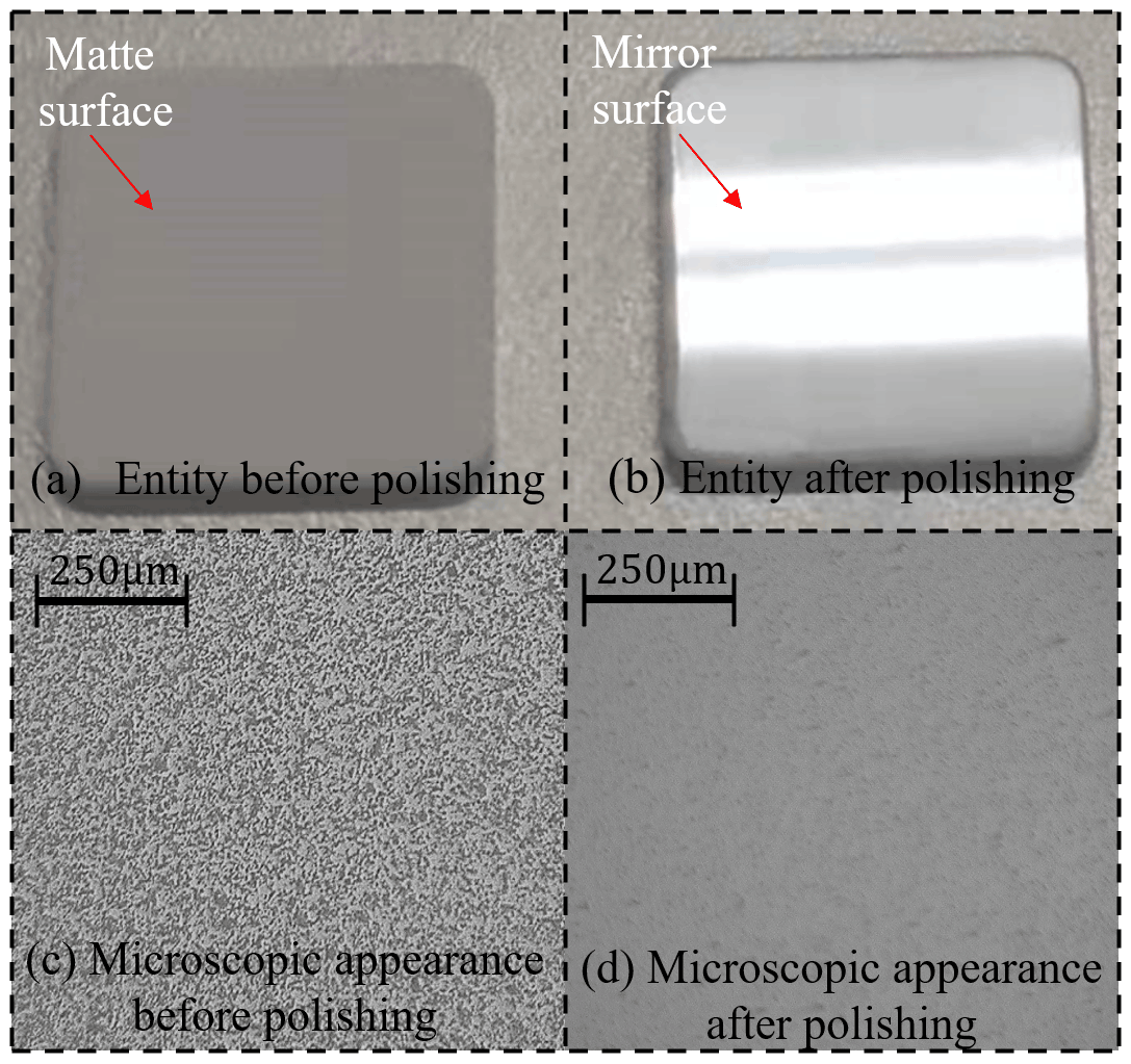
Figure 3Solid and microscopic appearance of workpiece.
3.1 Influence of different rotation speeds on the polishing effect
The above four groups of experiments were analysed. The following are the polishing experimental conditions: the polishing time is 6 h, the working pressure is 10 N, the speed of the carrier disc is 60 r min−1, the type of abrasive grain is diamond, the abrasive content is 7 vol %, the particle size is 2.5 µm, and the iron powder content is 35 vol %. The polishing sample of the workpiece at rotating speeds of 50, 60, 70, 80, and 90 r min−1 was observed at 60 times magnification with an ultra-depth-of-field microscope (Fig. 4). When the speed was 50 r min−1, the surface residual pits and the scratches generated by the previous process were not removed, and the surface quality was poor. When the speed was 60 r min−1, the surface pits were reduced, and the scratches were significantly reduced. When the speed was 70 r min−1, the surface pits were significantly reduced, the scratches were eliminated, and the surface was relatively uniform. When the speed was 80 r min−1, the number of surface pits increased, with a small number of scratches. When the speed was 90 r min−1, the surface scratches were more significant, and the surface was rough.
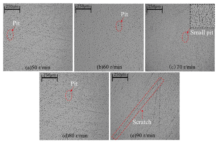
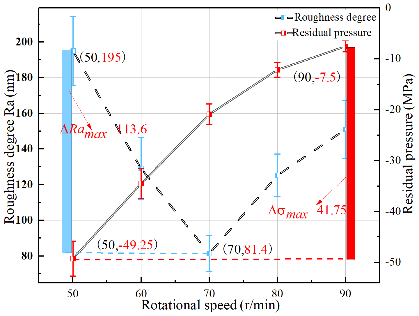
Figure 5 shows that the surface roughness of alumina ceramics decreased first and then increased when the rotation speed of the polishing disc changed from 50 to 90 r min−1. After undergoing polishing at the corresponding speed, the surface roughness of the alumina ceramics was 195, 129, 81.4, 125.3 and 151 nm, with a maximum difference of 113.6 nm. When the rotational speed went from 50 to 70 r min−1, with the increase in rotational speed, the frequency of contact between abrasive particles and workpiece surface increased, and the polishing efficiency gradually increased. When the rotating speed went from 70 to 90 r min−1, the linear velocity of the polishing pad increased gradually with the increase in rotating speed. The centrifugal force is greater than the tangential force of the magnetic force acting on the flux linkage, thereby destroying the chain structure inside the polishing pad and weakening the clamping force of the flux linkage on the abrasive particles. The liquid carrier, carbonyl iron powder and abrasive particles of the MRP fluid were separated from the polishing pad, mainly because the liquid carrier is largely separated from the polishing pad. Thus, the performance of the MRP fluid decreased and failed. The residual stress on the alumina ceramic surface decreased gradually from 50 to 90 r min−1. After polishing at the corresponding speed, the residual stresses on the alumina ceramic surface were −49.25, −34.48, −20.85, −12.13 and −7.5 MPa. The maximum residual stress difference on the alumina ceramic surface was 41.75 MPa. When the rotational speed is low, the linear velocity of the polishing disc is low, the centrifugal force is small, the magnetic linkage is relatively stable for the clamping of the abrasive particles, the polishing tangential force is relatively large, and the residual stress is large. When the rotational speed is high, the linear velocity of the polishing disc and the centrifugal force are large. Some abrasive particles were separated from the clamping of the flux linkage, the tangential force of polishing was relatively reduced, and the residual stress decreased. Finally, when the speed was 70 r min−1, the polishing quality is the best, and the roughness value is the smallest.
3.2 Influence of different polishing pressures on the polishing effect
The following are the polishing experimental conditions: the polishing time is 6 h, the speed of the polishing disc is 70 r min−1, the speed of the carrier disc is 60 r min−1, the type of abrasive grain is diamond, the abrasive content is 7 vol %, the particle size is 2.5 µm, and the iron powder content is 35 vol %. The polishing sample of the workpiece at pressures of 5, 10, 15, 20 and 25 N was observed at 60 times magnification with the ultra-depth-of-field microscope (Fig. 6). When the pressure was 5 N, the surface remained deep, and the diameter increased. When the pressure was 10 N, the residual deep pits disappeared, but the residual small pits were not completely removed. When the pressure was 15 N, no residual pit could be found on the surface, and the surface quality was good. When the pressure was 20 N, the surface appeared to have shallow pits and scratches. When the pressure was 25 N, the surface scratches became deeper and wider, and the surface quality was poor.
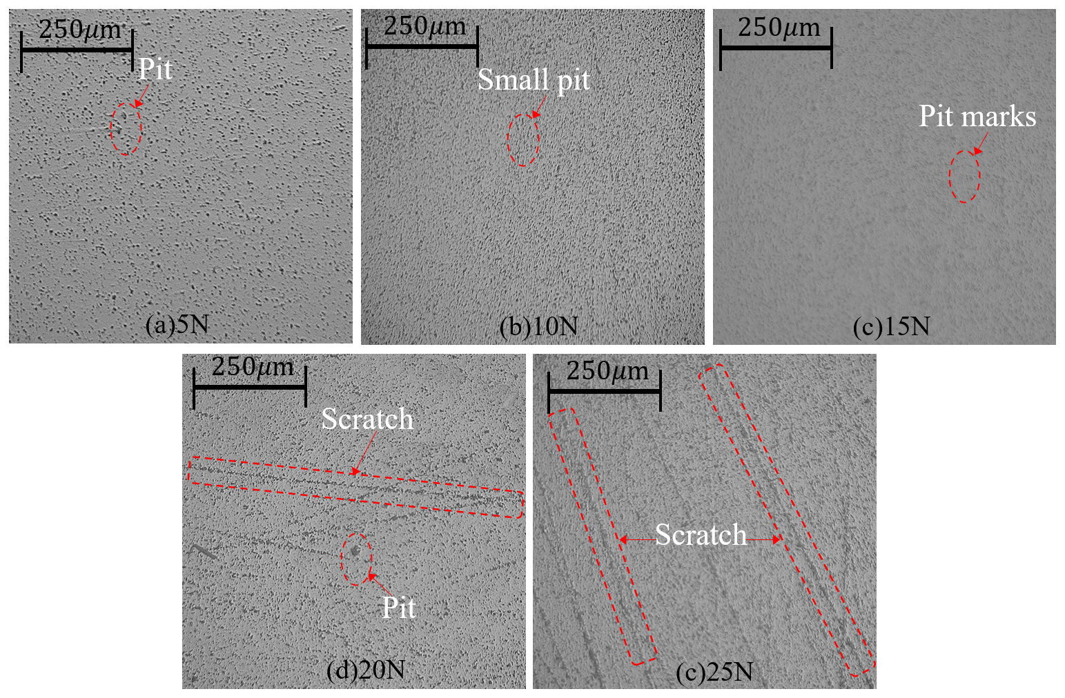
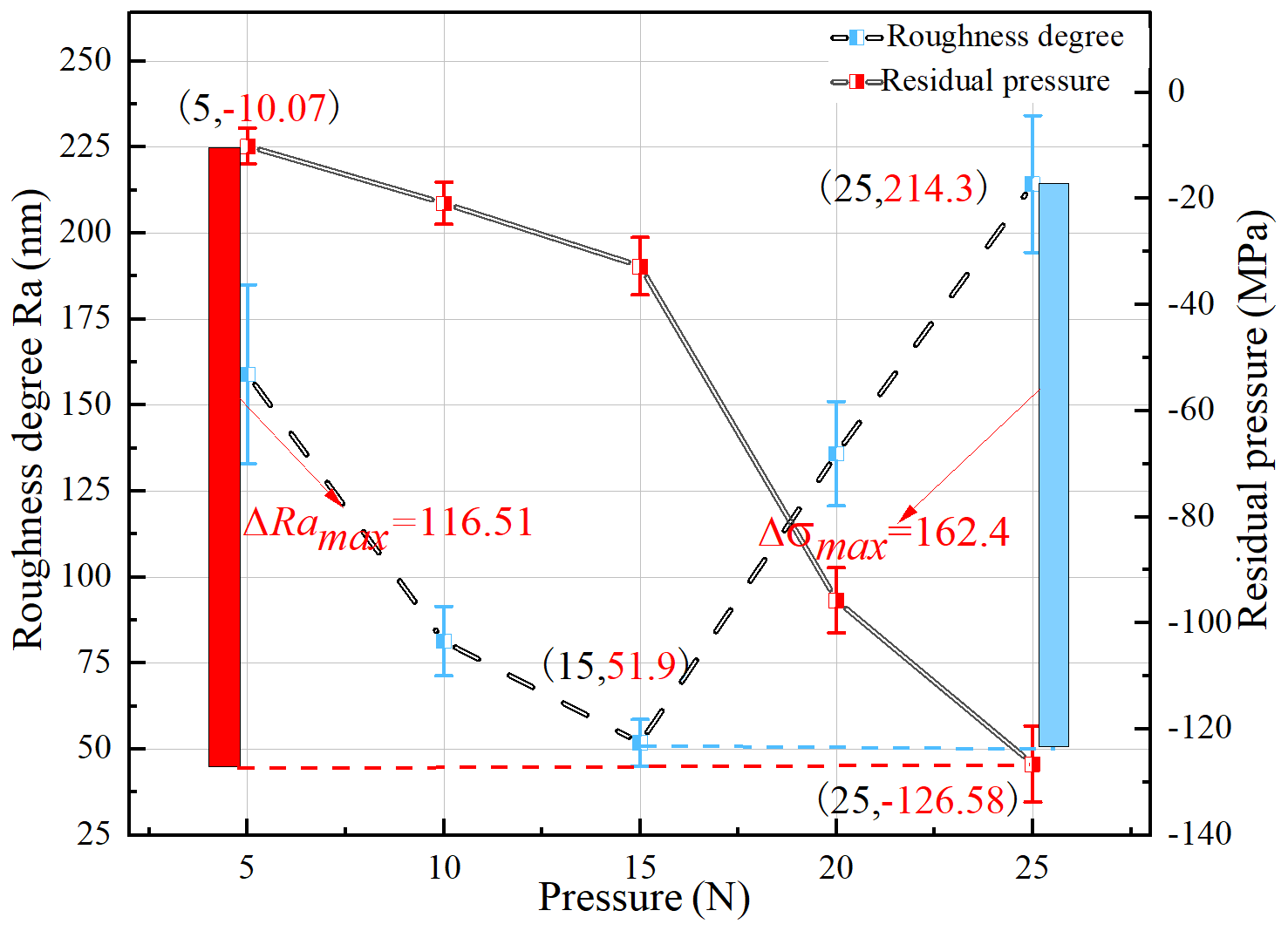
Figure 7 shows that the surface roughness of the alumina ceramics decreased first and then increased when the working pressure of the polishing disc was from 5 to 25 N. The surface roughness (Ra) of the alumina ceramics after polishing under the corresponding working pressures was 159, 81.4, 51.9, 135.9 and 214.3 nm, respectively. The maximum difference in the surface roughness of alumina ceramics was 162.4 nm. When the working pressure went from 5 to 15 N, with the increase in the working pressure, the cutting force of abrasive particles and workpiece surface polishing increased, and the polishing efficiency increased gradually. When the working pressure went from 15 to 25 N, with the increase in the working pressure, the thickness of the MRP fluid became increasingly thinner. When the polishing pressure was too large, the magnetic chain of the MRP fluid could be destroyed, and the abrasive particles fell off the magnetic chain. Thus, the performance of the MRP fluid could decrease and fail, which may cause the rigid grinding of the carrier plate on the surface of the abrasive particles and increase the surface roughness value. When the working pressure went from 5 to 25 N, the surface residual stress of the alumina ceramics increased gradually. The surface residual stress of the alumina ceramics after polishing under the corresponding working pressures was −10.07, −20.85, −32.71, −95.7 and −126.58 MPa. The maximum difference in the surface residual stress of the alumina ceramics was 116.3 MPa. When the working pressure was small, the MRP fluid magnetic chain thickness was relatively high, the abrasive and workpiece surface polishing cutting force were relatively small, and the residual stress was small. When the working pressure was high, the MRP fluid magnetic chain was thin, and the polishing pressure was too large to destroy the MRP fluid magnetic chain. The abrasive particles fell off the magnetic chain. Under the action of a large working pressure, the abrasive particles produced a large polishing cutting force with the workpiece surface, and the residual stress increased. Finally, when the working pressure was 15 N, the polishing quality was the best, and the roughness value was the smallest.
3.3 Influence of different abrasive particles on the polishing effect
The following are the polishing experimental conditions: the polishing time is 6 h, the speed of the carrier disc is 60 r min−1, the working pressure is 15 N, the abrasive content is 7 vol %, the particle size is 2.5 µm, the speed of the polishing disc is 70 r min−1, and the iron powder content is 35 vol %. The polishing sample of the workpiece when diamond, alumina, boron carbide and silicon carbide were used as polishing abrasives was observed at 60 times magnification with the ultra-depth-of-field microscope (Fig. 8). When the polished abrasive was diamond, no obvious pits and scratches on the surface were found, and the surface quality was good. When the polishing abrasive was alumina, the surface retained its deep pits with a large number thereof, and the surface quality was poor. When the polishing abrasive was silicon carbide, the number of surface pits decreased. When the polishing abrasive particle was boron carbide, the number of surface pits was further reduced, but the surface quality was poor.
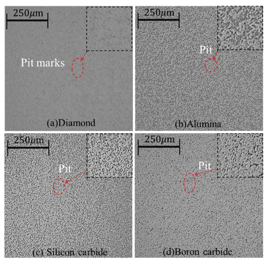
Figure 9 shows that different polishing abrasives affect the surface roughness and residual stress of alumina ceramics. Diamond, alumina, silicon carbide and boron carbide were used in this study. After polishing, the surface roughness values of the alumina ceramics were 51.9, 183, 91.8 and 71.1 nm, with a maximum surface roughness difference of 131.1 nm. The abrasive hardness from small to large was alumina, silicon carbide, boron carbide and diamond, corresponding to the polishing degree of the alumina ceramic surface. The best surface roughness of alumina ceramics was achieved when the polishing abrasive was diamond, followed by silicon carbide and boron carbide. The worst surface roughness was achieved when the polishing abrasive was alumina, due to the high hardness of alumina ceramics. Diamond has high hardness, thus being more suitable for polishing alumina ceramics. The residual stresses on the alumina ceramic surface after polishing with diamond, alumina, silicon carbide and boron carbide abrasive particles were −32.71, −8.65, −14.6 and −20.41 MPa, respectively, with a maximum difference of 24.06 MPa. A high abrasive hardness corresponded to greater residual stress generated by surface cutting under the same working pressure. The best polishing quality and the lowest roughness were achieved with the diamond polishing abrasive.
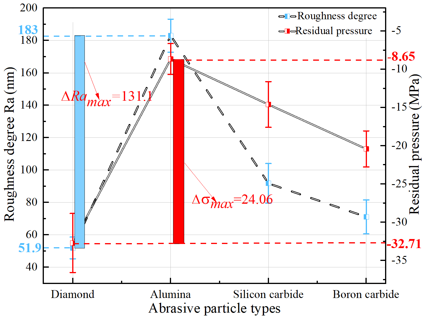
Figure 9Relationship between types of abrasive grains and surface roughness and residual stress.
3.4 Influence of different particle sizes on the polishing effect
The following are the polishing experimental conditions: the polishing time is 6 h, the iron powder content is 35 vol %, the type of abrasive grain is diamond, the polishing pressure is 15 N, the particle size is 2.5 µm, the speed of the polishing disc is 70 r min−1, the abrasive content is 7 vol %, and the wheel speed is 60 r min−1. The polishing sample of the workpiece at abrasive particle sizes of 0.5, 1, 1.5, 2 and 2.5 µm was observed at 60× magnification with the ultra-depth-of-field microscope (Fig. 10). When the particle size was 0.5 µm, the surface residue was deeper, and the diameter increased. When the particle size was 1 µm, the surface retained its incompletely removed pits with the same direction. When the particle size was 1.5 µm, the residual micropits on the surface were not completely removed. When the particle size was 2 µm, no pits were observed on the surface, and the surface quality was good. When the particle size was 2.5 µm, only a few small pits appeared on the surface.
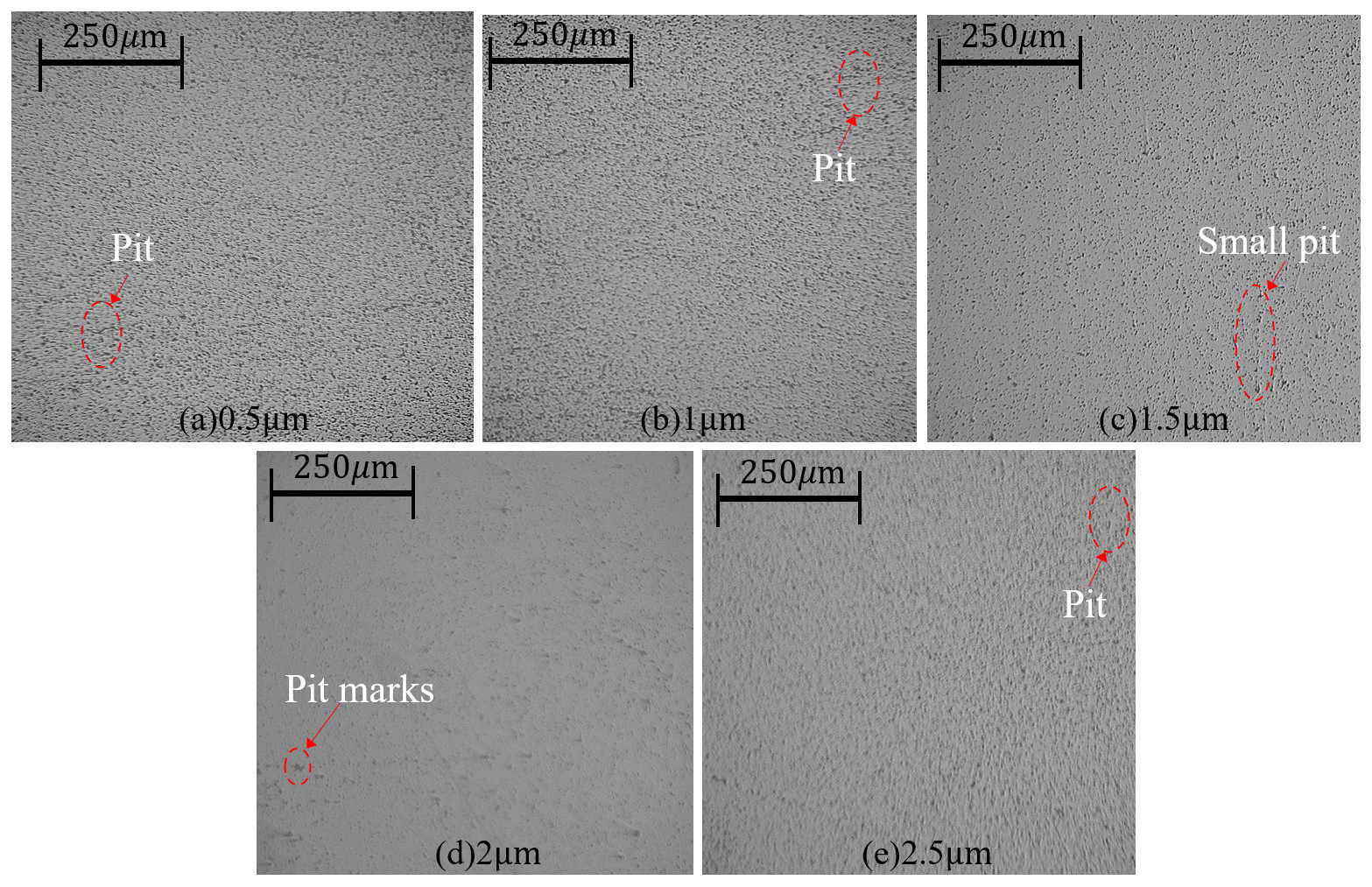
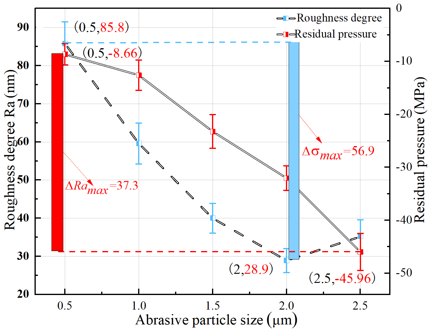
Figure 11 shows that when the particle size of the polished abrasive particles ranged from 0.5 to 2.5 µm, the surface roughness of the alumina ceramics first decreased rapidly, then slowly decreased and finally slowly increased. The surface roughness (Ra) of the alumina ceramics after polishing was 85.84, 59.6, 40, 28.9 and 35.2 nm, with a maximum difference of 56.9 nm. At a constant polishing abrasive content and a polishing abrasive particle size of 0.5 to 1.5 µm, the amount of polishing abrasive decreased, the pressure on polishing abrasive and the effective area of single polishing increased, the removal of surface-obvious anomalies and pits was accelerated, and the removal efficiency of polishing was higher with the increase in the particle size of the polishing abrasive. When the particle size of the polishing abrasive went from 1.5 to 2 µm, the reduction rate of the surface roughness became slow. As a result of the larger particle size of the polishing abrasive, a large clamping gap between the magnetic particles corresponded to a small magnetic clamping force of the polishing abrasive and thus a slow reduction in surface roughness. When the abrasive particle size went from 2 to 2.5 µm, the surface roughness increased slowly. As a result of the increase in abrasive particle size, the gap between magnetic particles led to the mismatch between magnetic particles and abrasive particle size, the number of polishing abrasive particles decreased, and the polishing quality of alumina ceramics decreased. The residual stresses on the alumina ceramic surface after polishing with the corresponding particle sizes are −8.65, −12.6, −23.22, −32.02 and −45.96 MPa, respectively, with a maximum difference of 37.3 MPa. At a constant content of polishing abrasive particles, the residual stress on the alumina ceramic surface increased gradually when the particle size of the polishing abrasive particles went from 0.5 to 2.5 µm. Moreover, at a constant content of polishing abrasive particles, a large particle size corresponded to fewer abrasive particles. The force acting on each polishing abrasive particle increased under constant polishing pressure. The polishing process generated scratches and increased residual stresses on the alumina ceramic surface. The best polishing quality and the lower roughness value were achieved at an abrasive particle size of 2 µm.
3.5 Influence of the polishing time on the polishing effect
The following are the polishing experimental conditions: the iron powder content is 35 vol %, the type of abrasive grain is diamond, the polishing pressure is 15 N, the particle size of 2.5 µm, the speed of the polishing disc is 70 r min−1, the abrasive content is 7 vol %, and the speed of the carrier disc is 60 r min−1. The polishing sample of the workpiece at polishing times of 2, 4, 6, 8 and 10 h was observed at 60 times magnification with the ultra-depth-of-field microscope (Fig. 12). When the polishing time was 2 h, more residual pits and poor surface quality could be found. When the polishing time was 4 h, the surface exhibited a small amount of incompletely removed pits. When the polishing time was 6 h, the surface's residual small pits were not completely removed, and the overall surface quality was good. When the polishing times were 8 and 10 h, no residual pits were found on the surface, and the surface quality improved.
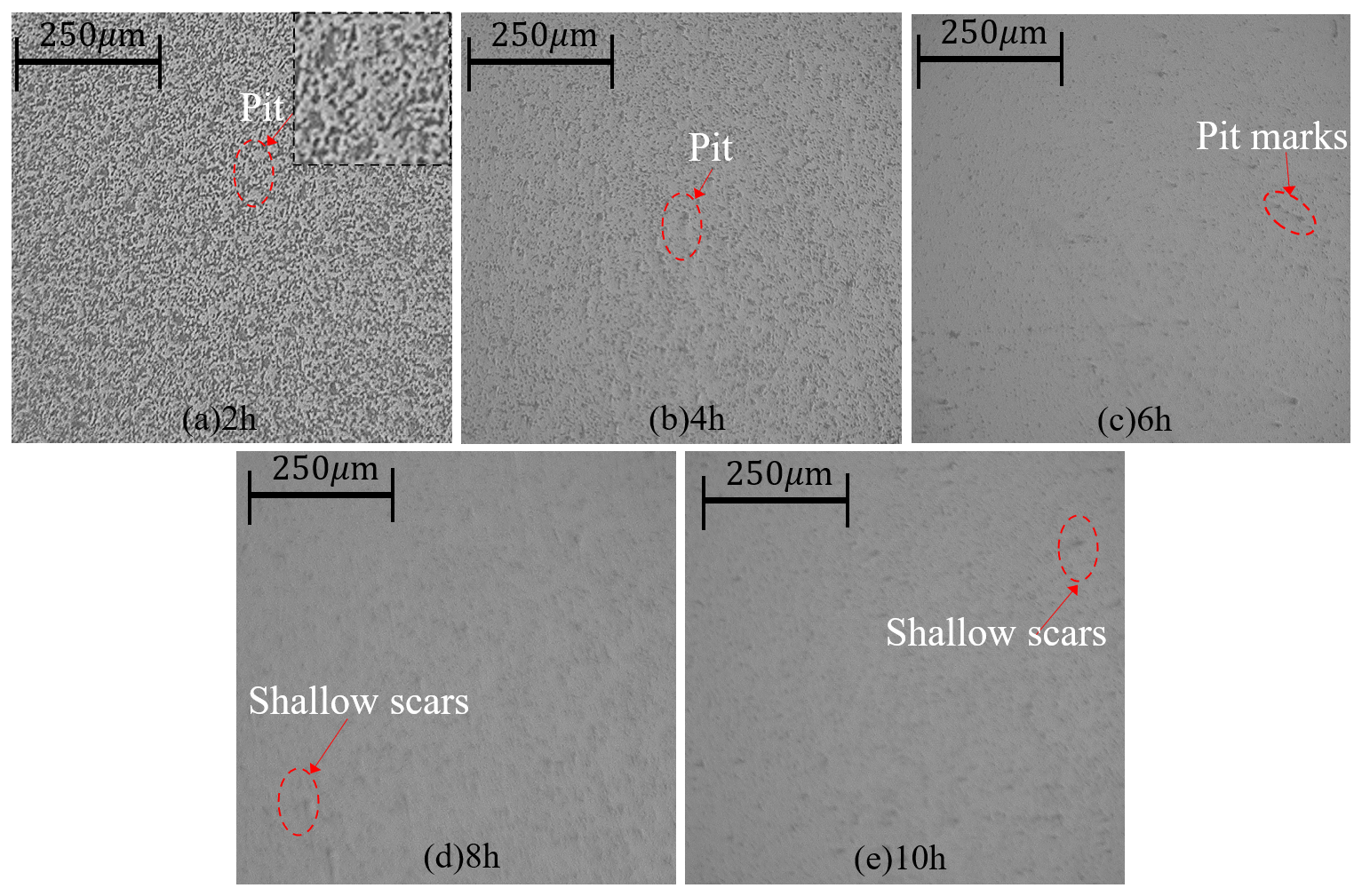
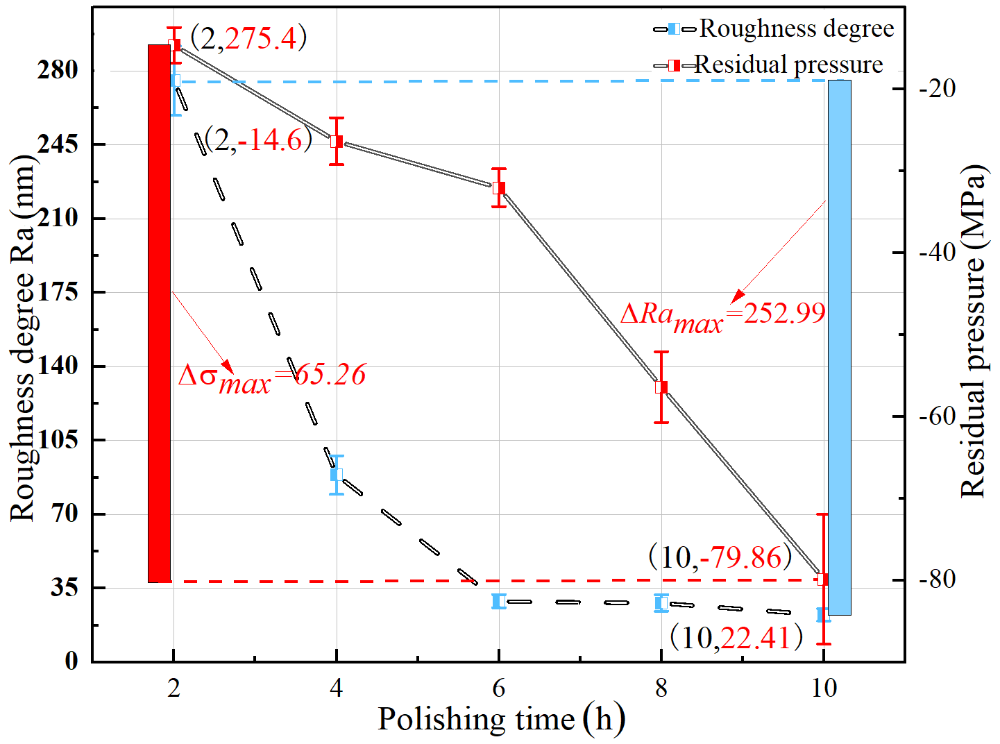
Figure 13 shows that when the polishing time was from 2 to 10 h, the surface roughness of alumina ceramics decreased rapidly and then tended to be stable. Under the corresponding polishing times, the surface roughness (Ra) of alumina ceramics was 275.4, 88.7, 28.9, 28 and 22.41 nm, with a maximum difference of 252.99 nm. When the polishing time was 10 h, the surface roughness of alumina ceramics was the smallest. When the polishing time went from 2 to 4 h, with the increase in polishing time, the number of effective scratches between polishing abrasive particles and the alumina ceramic surface increased, the alumina ceramic surface was rough in the initial stage, and the removal amount and polishing efficiency of the alumina ceramics were high. When the polishing time went from 4 to 6 h, the decrease in the surface roughness of the alumina ceramics slowed down significantly with the increase in polishing time. As the convex part of the alumina ceramic surface was basically removed, the pits were removed at the corresponding time, and the polishing efficiency was significantly reduced. When the polishing time went from 6 to 10 h, the surface roughness value of the alumina ceramics changed in a horizontal line, and the surface roughness value decreased slightly. The surface roughness of the alumina ceramics reached the limit as a result of the limitation of equipment and other factors. The polishing quality demonstrated little effect with prolonged polishing time. The residual stresses on the alumina ceramic surface after polishing at the corresponding polishing time were −14.6, −26.34, −32.02, −56.39 and −79.86 MPa, with a maximum difference of 65.26 MPa. When the polishing time went from 2 to 6 h, the residual stress increased slowly, mainly to remove the alumina surface bulge, the polishing abrasive particles scratched the alumina surface less frequently, and the alumina surface damage was relatively small. When the polishing time went from 6 to 10 h, the residual stress increased linearly, mainly to remove pits on the whole alumina surface, the number of scratches between alumina ceramic surface and polishing abrasive particles increased, and the sub-damage of the whole alumina ceramic surface was more obvious. Finally, when the polishing time was 6 h, the polishing efficiency for the alumina ceramic surface was the highest.
-
The pressurised three-point eccentric MRP device was designed to cope with the hard and brittle nature of alumina ceramics. Compared with the fixed-point gap polishing method, the applied pressure significantly improves the polishing efficiency, while the three-point eccentric MRP device results in better polishing uniformity. The centreline of the carrier disc is not on the same centreline as that of the polishing disc and a relative deviation angle is present, which reduces the polishing quality of the alumina ceramic substrate as a result of the linear speed difference. The carrier disc and polishing disc rotate in opposite directions, thereby facilitating the replacement of abrasive particles in the MRP solution, resulting in a more uniform distribution of the MRP solution inside and outside the polished workpiece surface.
-
The magnetic field generation device is designed using the principle of closed-loop magnetic induction loop, and the optimal arrangement is determined through comparative analysis of magnetic field simulation as a single closed-loop uniform magnetic field arrangement. The single closed-loop uniform magnetic field arrangement increases the effective area covered by the magnetic field and the magnetic field distribution is more uniform, and the strong magnetic field strength can reach 0.7–0.8 T.
-
The influence of different factors on the surface quality of the workpiece is analysed through polishing experiments. The surface roughness decreases and then increases as the speed of the polishing disc, the working pressure and the abrasive particle size increase. The residual stress decreases with increasing disc speed and increases with increasing working pressure and abrasive size. When the polishing disc speed is 70 r min−1, the working pressure is 15 N and the particle size is 2 µm, and a low residual stress and the best polished surface quality are achieved, with a surface roughness (Ra) of 28.9 nm.
All data included in this study are available upon request by contacting the corresponding author.
CZ, BC and XY contributed significantly to the conception and design of work, data acquisition, analysis and interpretation. YX contributed to the acquisition of simulation experimental data and data collation. SH helped with the writing and language.
The contact author has declared that neither they nor their co-authors have any competing interests.
Publisher's note: Copernicus Publications remains neutral with regard to jurisdictional claims in published maps and institutional affiliations.
This project has been supported by the Natural Science Foundation of Fujian Province (grant no. 2020J01874), the Fujian Province Industry-University-Research Joint Innovation Project (grant no. 2020H6028), the Program for Innovative Research Team in Science and Technology in Fujian Province University (2020; grant no. 12) and High-level talents foundation of Fuzhou Polytechnic (grant no. FZYRCQD 201903).
This research has been supported by the Natural Science Foundation of Fujian Province (grant no. 2020J01874).
This paper was edited by Jeong Hoon Ko and reviewed by three anonymous referees.
Chen, M., Liu, H., Cheng, J., Yu, B., and Fang, Z.: Model of the material removal function and an experimental study on a magnetorheological finishing process using a small ball-end permanent-magnet polishing head, Appl. Optics, 56, 5573–5582, 2017.
Davim, J. P., Santos, E., Pereira, C., and Ferreira, J.: Comparative study of friction behaviour of alumina and zirconia ceramics against steel under water lubricated conditions, Ind. Lubr. Tribol., 60, 178–182, 2008.
Fan, C., Xue, C., Zhang, L., Wang, K., Wang, Q., Gao, Y., and Lu, L.: Design and control of the belt-polishing tool system for the blisk finishing process, Mech. Sci., 12, 237–248, https://doi.org/10.5194/ms-12-237-2021, 2021.
Fan, N., Chai, L., Wang, P., and Liang, J.: The effect of ceramic friction pairs on the tribocorrosion behavior of AISI 304 stainless steel in seawater, Ind. Lubr. Tribol., 71, 779–786, 2019.
Guo, C., Liu, J., Li, X., and Yang, S.: Effect of cavitation bubble on the dispersion of magnetorheological polishing fluid under ultrasonic preparation, Ultrason. Sonochem., 79, 105782, https://doi.org/10.1016/j.ultsonch.2021.105782, 2021.
Heng, L., Kim, J. S., Tu, J.-F., and Mun, S. D.: Fabrication of precision meso-scale diameter ZrO2 ceramic bars using new magnetic pole designs in ultra-precision magnetic abrasive finishing, Ceram. Int., 46, 17335–17346, 2020.
Luo, H., Guo, M., Yin, S., Chen, F., Huang, S., Lu, A., and Guo, Y.: An atomic-scale and high efficiency finishing method of zirconia ceramics by using magnetorheological finishing, Appl. Surf. Sci., 444, 569–577, 2018.
Nie, M., Cao, J., Li, J., and Fu, M.: Magnet arrangements in a magnetic field generator for magnetorheological finishing, Int. J. Mech. Sci., 161, 105018, https://doi.org/10.1016/j.ijmecsci.2019.105018, 2019.
Singh, M. and Singh, A. K.: Magnetorheological finishing of variable diametric external surface of the tapered cylindrical workpieces for functionality improvement, J. Manuf. Process., 61, 153–172, 2021.
Song, W., Li, H., Ma, J., Hu, Z., and Shi, P.: Experimental investigation of the magnetorheological polishing process with roller, Ind. Lubr. Tribol., 70, 1060–1065, https://doi.org/10.1108/ILT-12-2017-0367, 2018.
Vila-Nova, T. E. L., de Carvalho, I. H. G., Moura, D. M. D., Batista, A. U. D., Zhang, Y., Paskocimas, C. A., Bottino, M. A., and de Souza, R. O. A.: Effect of finishing/polishing techniques and low temperature degradation on the surface topography, phase transformation and flexural strength of ultra-translucent ZrO2 ceramic, Dent. Mater., 36, e126–e139, 2020.
Wang, C., Cheung, C. F., Ho, L. T., Yung, K. L., and Kong, L.: A novel magnetic field-assisted mass polishing of freeform surfaces, J. Mater. Process. Tech., 279, 116552, https://doi.org/10.1016/j.jmatprotec.2019.116552, 2020.
Wang, R., Xiu, S., Sun, C., Li, S., and Kong, X.: Study on material removal model by reciprocating magnetorheological polishing, Micromachines, 12, 413, https://doi.org/10.3390/mi12040413, 2021.
Wang, Y., Xie, W., and Wu, D.: Rheological properties of magnetorheological suspensions stabilized with nanocelluloses, Carbohyd. Polym., 231, 115776, https://doi.org/10.1016/j.carbpol.2019.115776, 2020.
Xia, Z., Fang, F., Ahearne, E., and Tao, M.: Advances in polishing of optical freeform surfaces: a review, J. Mater. Process. Tech., 286, 116828, https://doi.org/10.1016/j.jmatprotec.2020.116828, 2020.
Xie, Z. and Zhu, W.: Theoretical and experimental exploration on the micro asperity contact load ratios and lubrication regimes transition for water-lubricated stern tube bearing, Tribol. Int., 164, 107105, https://doi.org/10.1016/j.triboint.2021.107105, 2021.
Xie, Z. and Zhu, W.: An investigation on the lubrication characteristics of floating ring bearing with consideration of multi-coupling factors, Mech. Syst. Signal Pr., 162, 108086, https://doi.org/10.1016/j.ymssp.2021.108086, 2022.
Xu, Z., Wang, J., Yin, S., Wu, H., and Yi, L.: Compound Machining of Tungsten Alloy Aspheric Mould by Oblique-axis Grinding and Magnetorheological Polishing, Int. J. Precis. Eng. Man., 22, 1487–1496, 2021.
Yang, Y., Liu, F., Chang, Q., Hu, Z., Wang, Q., and Wang, Y.: Preparation of fly ash-based porous ceramic with alumina as the pore-forming agent, Ceramics, 2, 286–295, 2019.
Yan, X., Fan, C., Wang, W., Liu, X., and Chen, B.: Experimental and simulation study of the dynamic characteristics of friction force under third-body intrusion behaviour, Mech. Syst. Signal Pr., 168, 108726, https://doi.org/10.1016/j.ymssp.2021.108726, 2022.
Zhao, P., Jia, Y., Xie, J., Wang, T., Zhang, C., and Fu, J.: Magnetic levitation for polymer testing using magnet array, Polym. Test., 103, 107361, https://doi.org/10.1016/j.polymertesting.2021.107361, 2021.