the Creative Commons Attribution 4.0 License.
the Creative Commons Attribution 4.0 License.
 | 19 May 2022
Priority flow divider valve and its dynamic analysis using various hydraulic drive systems: a bond graph approach
Dharmendra Kumar
Om Prakash
Kaushik Kumar
The priority flow divider valve (PFDV) is used in power hydraulic system to split the supply flow in dual paths, i.e., primary path and secondary path. The flow ratio in each path is either predetermined or can be adjustable as per the loading conditions. The stated properties of the valve can be applied in a steering mechanism in automobile and a hydrostatic power transmission unit in a wind turbine. In a steering mechanism, it helps the system to perform two different functions against two different loads simultaneously, whereas, in a wind turbine, it can be used in hydrostatic power transmission unit to reduce the power fluctuation obtained from it. The hydrostatic power transmission system with PFDV (SMHPTSPFDV) used in a steering mechanism and the hydrostatic power transmission system with PFDV (WTHPTSPFDV) used in a wind turbine are modeled using the bond graph technique, and simulated in SYMBOLS Shakti software to analyze the steady and dynamic performance of the PFDV. The user-defined rectangular and sinusoidal variable pump speed has been used as inputs for system performance analysis. It is found that the PFDV may handle dual loads simultaneously, and it eliminates the use of multiple control valves to operate the same dual loads. Hence, it not only improves the system stability but also reduces the maintenance cost of the system. Moreover, the power and energy loss through the PFDV have been analyzed for both applications. It has been found that the power loss through the PFDV is higher when it is connected with SMHPTSPFDV. Also, the influences on the power and energy loss through PFDV are analyzed under various loading conditions.
- Article
(3559 KB) - Full-text XML
- BibTeX
- EndNote


A hydrostatic transmission system generally transmits power from one rotating element to another rotating element using a fluidic medium. It is capable of transmitting higher power in a compact area. The well-known components for a hydraulic system are a hydraulic pump, different control valves, an accumulator, and an actuator or hydraulic motor. The overall efficiency of a hydraulic system is an important parameter, and it is adversely affected by the leakages from its different components. The leakages are more with the increment of the number of hydraulic components and hence decrease the overall efficiency of the hydraulic system. Therefore, an effective hydraulic system design may improve the overall efficiency of the system (Ding et al., 2020; Mahato and Ghoshal, 2021). When it is required to perform dual functions by a hydraulic power system, the engagement of the hydraulic components are generally more. Hence, the probability of affecting the overall efficiency of the system is comparatively higher. To reduce the engagement of the hydraulic components or to improve the system design, a priority flow divider valve (PFDV) is a key component of a dual-function deliverable hydraulic system.
A PFDV performs a crucial role when two hydraulic circuits or two hydraulic actuators function simultaneously. This is a very high-precision hydraulic component, and its primary port orifice area is adjustable as per the primary load, whereas the secondary port allows the excess flow to pass through it. Sometimes the flow is split into a predefined ratio (Alderson and Truesdell, 1980). An auto-regulated high-precision flow divider/combined valve has been investigated by Fedoroff et al. (1992). The authors have developed a linearized model of the valve and described its operation in detail. Generally, the flow divider valves are of the following two types: rotary- or gear-type or a spool-type flow divider valve. The rotary-type flow divider valve provides better accuracy compared to the spool-type flow divider valve. But the spool-type flow divider valves are more flexible regarding the design and manufacturing process. Also, they can easily integrate with other components (Cheng, 2010). Metwally et al. (2012) presented a special split-spool-type flow divider valve, and the dynamic and static characteristics at various loading pressures have been studied. Another work by Vacca and Cerutti (2007) developed an algorithm for analyzing and optimizing the hydraulic components parameters. The algorithm is based on the response surface with steepest descent method that provides advantages of design of experiments techniques. The stated algorithm has been applied on a two-way flow-divider spool valve. A normal flow-divider valve splits the flow into two different actuators or circuits, such that the flow ratio does not depend on the load pressures. But in reality, it is very difficult to vary the flow ratio after manufacturing. To overcome the stated issue, Wiens (2004) and Wiens et al. (2005) introduced a new design of a flow divider valve with an adjustable flow ratio. The basic principle of the proposed valve is similar to the typical flow divider valve. But the effective pressures or the forces acting on the spool ends are modified by the pilot stage. Recently, Coskun et al. (2017) designed a PFDV and investigated the input parameters by a simulation using a one-dimensional simulation technique. Also, the simulation responses are validated experimentally. Darling et al. (1999) designed an integrated hydraulic supply system with the help of a PFDV. The PFDV assists in controlling the power supply to the power steering and braking system of a vehicle. Also, the PFDV is a critical part of the hydraulic system that is used in mining machineries. Kumar et al. (2019b) used the PFDV in a typical power hydraulic circuit of a mining equipment to drive the twin hydromotor simultaneously. Thereafter, the same power hydraulic system is considered for performing the fault detection, isolation, and prognosis by Kumar et al. (2019a). Besides, some literature has been found regarding the use of the PFDV in wind power applications. Mahato et al. (2018) used the PFDV in a wind turbine power transmission system to reduce the speed fluctuation of the Pelton wheel. The authors used a well-known on/off controller to reduce the power fluctuation in the wind turbine. Besides, the other closed-loop conventional controllers, such as PI (proportional integral), PD (proportional derivative), PID (proportional integral derivative), etc., can be implemented for the same function. However, an inverse model-based controller that maps the desired output into the input of the controller can replace the closed-loop controller. The popular inverse model-based control techniques are a neural network inverse model control strategy (Hussain et al., 2014), a system inversion-based control (Tripathi et al., 2022), etc. Presently, the inverse model-based controller is popularly used in various industries, and its principle can be implemented in open-loop off-the-shelf controllers (Giacomelli et al., 2018). In 2016, Fan et al. (2016) used a similar type of proportional flow control valve to control the pump flow. The stated proportional flow control valve divides the pump flow into two different paths and reduces the power fluctuation in wind turbine. This work is based on simulation, and the valve, i.e., proportional flow control valve, which is used to control the pump flow, is quite different in working principle from PFDV. However, the purpose of use for both valves, i.e., PFDV and proportional flow control valve, is similar. Also, the manufacturing feasibility of the proportional flow control valve is highly challenged and not cost-effective as per its design. Therefore, the flow divider valve can be used for both applications, i.e., to perform dual functions against dual loads concurrently using a single hydraulic pump and to generate stable power in wind turbine using a hydraulic power transmission system. As the stated valve is key equipment for these two identified applications, it is, thus, highly important to describe the detailed modeling and dynamic analysis of the proposed valve. The present study covers the detailed analysis of the flow divider valve in both applications.
This study addresses the detailed bond graph modeling of two simple power hydraulic systems with a PFDV. The first hydraulic system with PFDV, i.e., SMHPTSPFDV is based on performing dual functions concurrently against dual loads in steering mechanism whereas the second hydraulic system with PFDV, i.e., WTHPTSPFDV is designed to obtain a constant power from a wind turbine against a variable input to the system. Both systems, SMHPTSPFDV and WTHPTSPFDV, are simulated to analyze the steady and dynamic performance of the PFDV by applying various unstable inputs using SYMBOLS Shakti software (Samantaray and Mukherjee, 2006). This study is application based and presents dual application scopes of the PFDV in the signal platform. A bond graph is chosen for modeling the systems because it has a unified multiphysics system modeling tool and is used for the graphical representation of a physical dynamical system with power exchange among system components. Also, it is highly capable of interacting with multiple energy domains (Mukherjee et al., 2006; Borutzky, 2017; Merzouki et al., 2013; Mahato et al., 2017). The power and energy loss through the PFDV have been analyzed for both applications. Also, the influences on power and energy loss through PFDV are analyzed under various loading conditions.
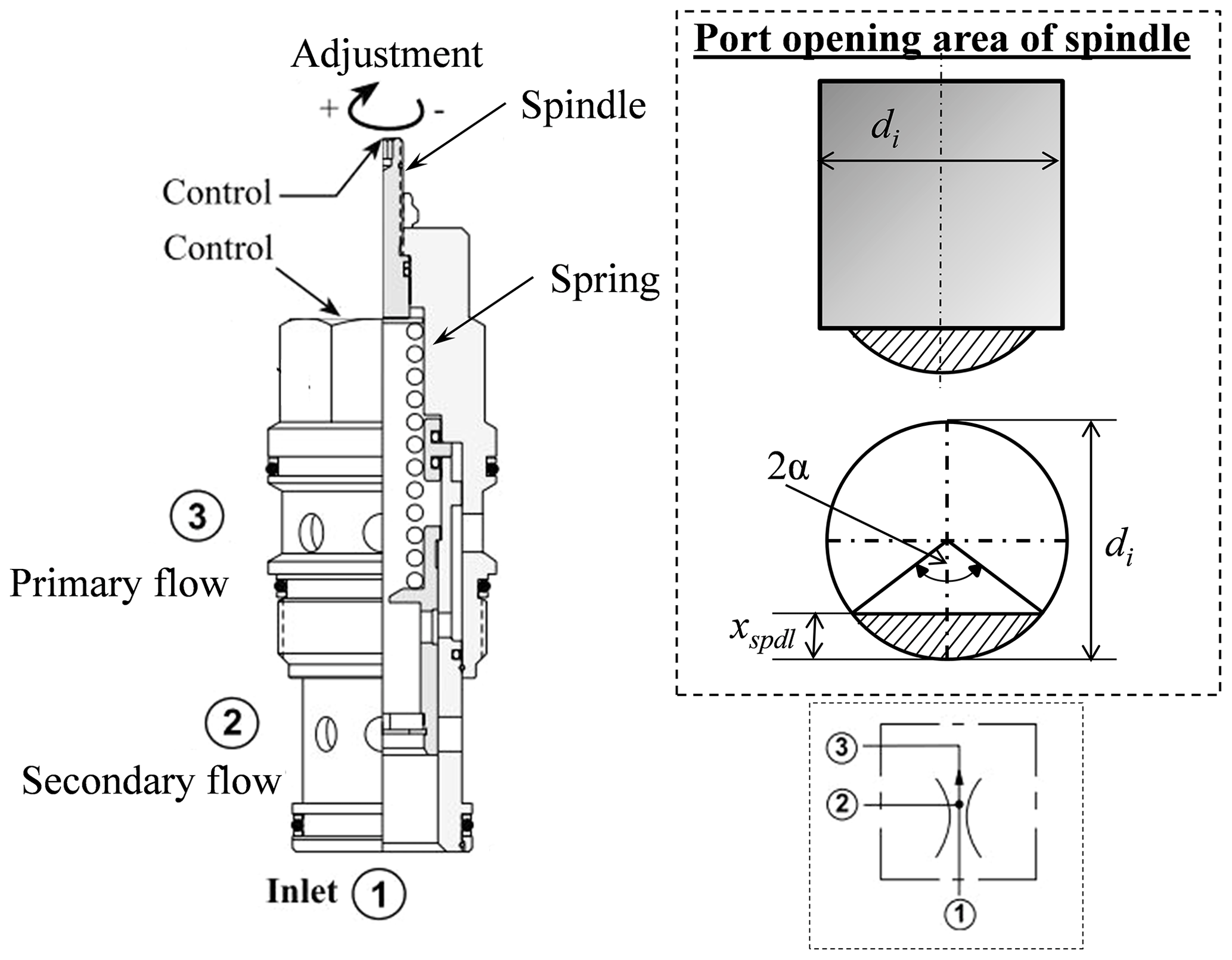
According to the actuation process, PFDV is of two types, i.e., spool type and rotary or gear type. A spool-type PFDV is designed to deliver proportional flows from two outlets, a priority flow from one outlet, and excess flow from another outlet. Besides, the rotary or gear type PFDV differs from its actuation process, and it has a rotary spindle. The main components in a spool-type PFDV are the housing with an inlet port and two outlet ports, a compression spring, and an internal moveable spindle/spool. The spindle movement controls the flow rate through the primary and the secondary port of the PFDV. The cross-sectional view of the PFDV is shown in Fig. 1.
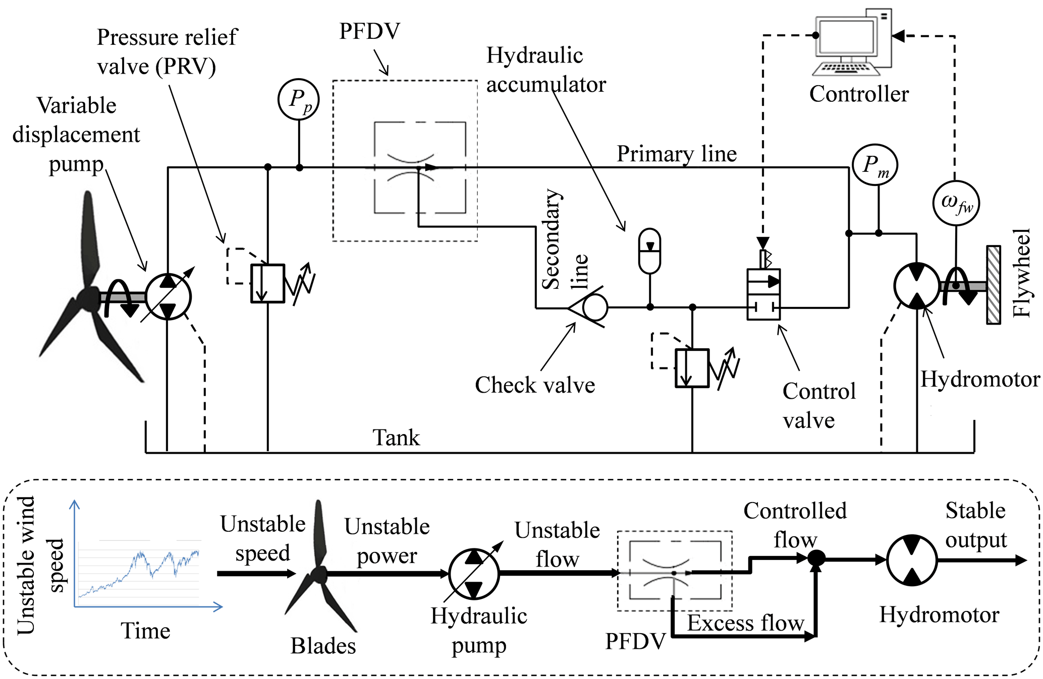
Power hydraulic systems transmit power using a fluidic medium. It converts the mechanical power from an engine or an electric motor to hydraulic power by rotating the shaft of a hydraulic pump. The hydraulic pump supplies flow to the control valves that direct the same flow to the hydraulic actuators and convert the hydraulic power back to mechanical power. In this study, two different open-loop hydraulic drive systems, i.e., SMHPTSPFDV and WTHPTSPFDV (refer to Figs. 2 and 3, respectively), are identified to analyze the performance of the PFDV. The SMHPTSPFDV is useful for performing two different functions concurrently using PFDV. Besides, another WTHPTSPFDV is suitable for supplying constant flow whenever the input flow is of a fluctuating nature. This stated concept is preferable in wind turbine power transmission systems to produce stable power.
In Fig. 2, a variable displacement hydraulic pump is used to supply a variable flow to the PFDV. The PFDV is connected with two different loads, namely a primary load and a secondary load of the steering system. The PFDV directs the pump flow towards the primary and secondary loads of the steering system. It controls the pump flow by controlling the movement of the spindle as per the loading condition of the system. Additionally, a pressure relief valve is incorporated between the hydraulic pump and the PFDV to maintain the normal system pressure and is hence used as a safety valve. The dynamic model of the steering system is not discussed in the present study, as the focus of the study is to analyze the performance of the PFDV using steering mechanism. More details about the dynamic model of the steering system are discussed by Chen and Guo (2020) and Wang et al. (2020).

The scheme to obtain a constant speed from the flywheel using a PFDV and an accumulator is shown in Fig. 3. In this scheme, a variable flow is supplied to the PFDV using a variable displacement hydraulic pump. The primary flow of the PFDV is adjusted and fixed at a threshold value as per the stable loading condition. If the supplied flow from the hydraulic pump is exceeded to maintain the stable loading, then the extra amount of flow supplied by the pump is allowed to pass through the secondary port of the PFDV. Thus, the excess flow is stored in the accumulator in the secondary line of the system. Contrarily, when the supply flow from the pump to the PFDV is insufficient, then the primary flow is unable to supply the required flow to the hydraulic motor to maintain the constant speed of the flywheel. In such a situation, the control valve receives a signal from the on/off controller. Thereafter, the control valve is enabled and allows the secondary line to flow to the hydraulic motor. In the secondary flow line, the accumulator releases the stored fluid to the hydraulic motor. Therefore, the stored fluid of the accumulator compensates the flow to the hydraulic motor and helps to maintain a constant speed of the flywheel whenever the pump supply is insufficient. The stated power hydraulic system can replace the mechanical power transmission in a wind turbine application to obtain stable power from it.
3.1 Bond graph modeling of SMHPTSPFDV
This section presents the bond graph modeling of the open-loop SMHPTSPFDV to perform dual functions simultaneously. The bond graph model is shown in Fig. 4. The developed dynamical model of the hydraulic system manages some assumptions, which are as follows:
-
Negligible fluid inertia
-
Tank pressure is atmospheric
-
Fluid properties do not vary with temperature
-
Pump and motor leakages are considered only for study purposes
-
Resistive and the capacitive effects are lumped wherever appropriate
-
Hydraulic pump and motor specifications can be changed as per the loading condition of the system.
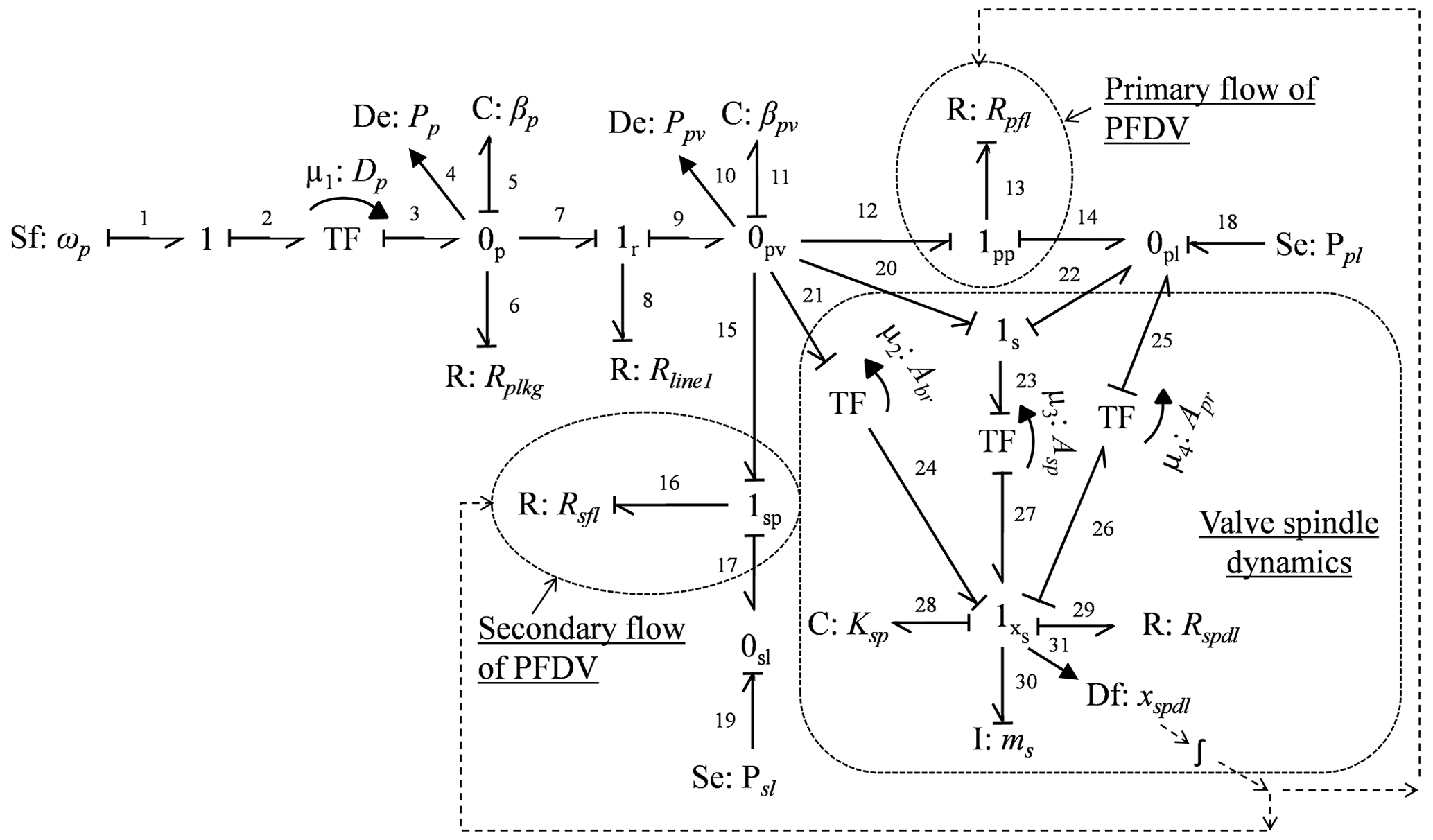
A variable speed control electric motor helps to supply a variable flow from the hydraulic pump to the PFDV. The angular speed of the shaft of the hydraulic pump (ωp) is represented by a source of flow (Sf1) generalized bond graph element. The mechanical energy of the shaft is converted into hydraulic energy by a transformer generalized bond graph element (TF), where the volume displacement rate of the hydraulic pump (Dp) is assigned as the modulus of TF. The bulk stiffness of the working fluid (βp) and the external leakage (Rplkg) of the hydraulic pump are represented by generalized bond graph capacitive element (C5: βp) and resistive element (R6: Rplkg), respectively, at 0p junction. The measured pressure at the pump plenum is indicated by Pp, which can be computed from the definition of the bulk modulus of the flowing fluid, and it is expressed as follows:
where ∀sw is the constant line volume, which includes the average effective volume of gerotor lobes. The pressure relief valve is used for safety purposes, and its flow is modeled as follows:
where, the pressure relief valve resistance (Rline1) is represented by the element R8 at 1r junction. Cd_rlv, arlv and Prlv_set are the co-efficient of discharge, port area, and set pressure of the relief valve, respectively. The C11 element at 0pv junction represents the bulk stiffness of the working fluid (βpv) at the PFDV plenum. The resistances of the primary port and the secondary port of the PFDV are modeled by resistive elements R13(=Rpfl) and R16(=Rsfl), respectively. Similarly, the primary load (Ppl) and the secondary load (Psl) are expressed by the source of effort elements Se18 and Se19, respectively. The PFDV spindle travels due to an effective force which is generated due to three different pressure forces, such as pressure at PFDV plenum (Ppv), pressure due to primary load (Ppl), and pressure due to secondary load (Psl). The transformer element (TF) which is connected between 1s and 1xs junctions, converts the pressure force into the mechanical force by assigning the area of the spindle (Asp) as the modulus of the TF. The displacement of the spindle (xspdl) is detected by a displacement sensor at 1xs junction. The flow resistances of the PFDV are varied, as per the spindle displacement of the PFDV. The mass (msp) and the stiffness (Ksp) of the spindle spring are expressed by I30 and C28 elements at 1xs junction, respectively. Also, the viscous resistance of the spindle (Rspdl) is expressed by R29 in the bond graph model. The pressure at PFDV plenum (Ppv) is expressed as follows:
where ∀swpv and vspdl are the constant line volume and the linear velocity of the PFDV spindle, respectively. The PFDV splits the pump flow into two different paths, i.e., primary and secondary paths. The flow through the primary and secondary ports of the PFDV depends on the displacement of the valve spindle (xspdl), which is estimated by solving the ordinary differential equation, i.e., Eq. (4), obtained from the bond graph model.
where Asp, Abr, and Apr are the area of the PFDV spindle, the area towards the secondary port, and the area towards the primary port of the PFDV, respectively. The stiffness and the mass of the spring are denoted by Ksp and ms, respectively. The viscous resistance works against the movement of the spindle of the PFDV, and it is denoted by Rspdl.
In PFDV, the primary flow is adjusted as per the predefined ratio or as per the primary loading condition, and the other excess flow is allowed to pass through the secondary port of the PFDV. The primary flow of the PFDV (Qpfl) is expressed as follows:
where is the flow constant. The Cd_pfl is the coefficient of discharge through the primary port of PFDV. xi is the desired spindle displacement supplying the necessary flow to operate the primary circuit successfully. The Ai_pfl and Aimax_pfl are the instantaneous opening area and the maximum opening area of the primary port of the PFDV, respectively. The Ai_pfl depends on the Aimax_pfl, size of the indenter, i.e., diameter of the indenter (di), angle of the indentation (α), and the displacement of the valve spindle, etc. (Watton, 2009). It can be expressed as follows:
Similarly, the secondary flow through the PFDV (Qsfl) is expressed as follows:
where Cd_sfl is the coefficient of discharge through the secondary port of the PFDV. Ai_sfl is the instantaneous flow area through the secondary port of the PFDV. It is the function of maximum flow area through the secondary port of the PFDV (Aimax_sfl), displacement of the spindle towards the secondary port (ys), size of the indenter, and angle of indentation (Watton, 2009). The ys is the same as the excess displacement of the spindle, i.e., . Therefore, the Ai_sfl is expressed as follows:
The bond graph model derives the state–space equations of the physical hydraulic system, given as Eqs. (11)–(13). These are derived using a well-known computational causality method and step-by-step algorithm (Mukherjee et al., 2006; Borutzky, 2017; Merzouki et al., 2013; Mahato et al., 2017). The storage elements, having lumped the single port (C and I elements) with the integral causality grants, led to one coupled differential equation of the first order. Besides, in multiport elements, which possess the integral causality, the numbers of state equations are the same as the number of bonds connected to them. Therefore, the total number of generated differential equations is equal to the sum of integrally causalled bonds associated with the bond graph model. The C and I elements, which are integrally causalled, are related with a generalized charge for electrical domain or generalized displacement for the mechanical domain, i.e., and generalized momentum i.e. , respectively. e and f are the generalized effort and flow, respectively. Here, the mathematical equation is systematically and algorithmically derived using SYMBOLS Shakti software (Samantaray and Mukherjee, 2006).
3.2 Bond graph modeling of WTHPTSPFDV
The bond graph model of the physical WTHPTSPFDV to obtain a stable speed is shown in Fig. 5. This bond graph model is similar to the one in Fig. 4, except for the additional modeling of the check valve, accumulator, control valve, hydraulic motor, and the flywheel.
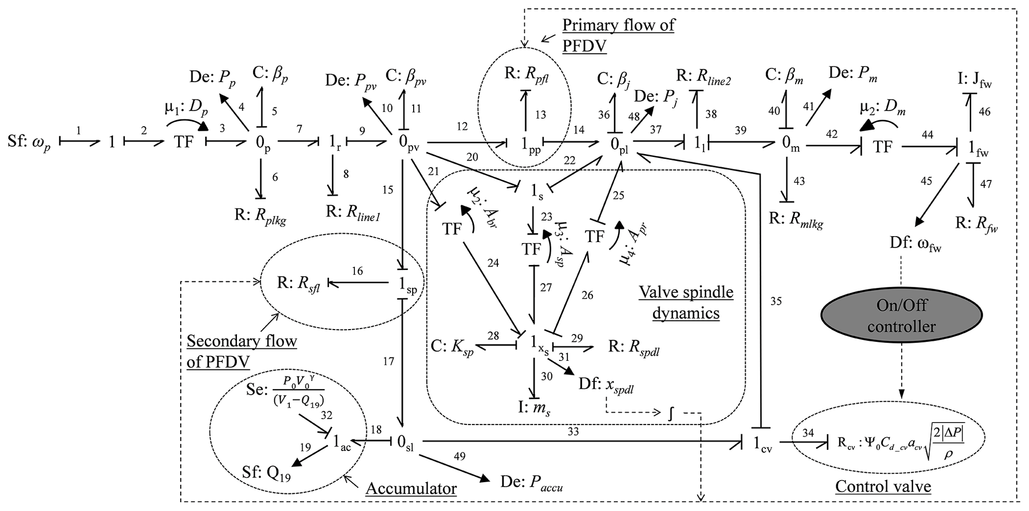
The accumulator stores excess energy and releases the same whenever the pump supply is insufficient to compensate the demand flow as per the load. The accumulator is modeled at 1ac junction by the Se32 element. It represents the final pressure (P2) that is developed by the accumulator. The accumulator follows the nonlinear relationship between pressure and volume. It is assumed that the heat loss through the accumulator is negligible. Therefore, the pressure–volume relationship should be reversible adiabatic and it is expressed as follows:
where ∀1 and P1 are the initial volume and pressure of the accumulator, respectively. γ is the specific heat capacity ratio of air. Δ∀ is the contemporary volume displacement obtained from the integration of the flow output from the flow detector Sf19 (=Q19).
The control valve is modeled at 1cv junction. The resistance of the control valve port is represented by a resistive element R34 (=Rcv). The port opening area of the control valve is controlled as per the speed of the flywheel. The control valve is in open condition only when the flywheel speed is lower than its threshold speed. This threshold speed is fixed as per the load of the system. Therefore, the flow through the control valve (Qcv) is expressed as follows:
where Cd_cv and acv are the coefficient of discharge and the port opening area of the control valve, respectively. Ψ0 is the on/off controller output which checks the flywheel speed (ωfw) against the constant threshold speed (ωth). It is expressed as follows:
The primary flow and the secondary flow of the PFDV are combined at 0pl junction. The bulk stiffness of the working fluid at the same junction is denoted by C36(=βj), whereas the pressure (Pj) is measured by another sensor, and it is represented by an effort detector (De48). The Pj is computed from the definition of bulk modulus of the flowing fluid, and it is expressed as follows:
where ∀j and βj are the constant line volume and the bulk modulus of the working fluid at the junction of the primary and the secondary flow of the PFDV. The pipe resistance (Rline2) is represented by R38 at 1l junction.
The hydraulic motor is modeled at 0m junction in the bond graph model. At the same junction, the external leakage of the hydraulic motor (Rmlkg) and the bulk stiffness of the working fluid at the motor plenum (βm) are represented by the resistive element (R43) and capacitive element (C40), respectively. The measured pressure at the motor plenum is indicated by Pm, and it is obtained from the definition of bulk modulus of the flowing fluid, refer to Eq. (18), in the following:
where ∀m and βm are the constant line volume and the bulk modulus of the working fluid at the motor plenum. The line volume represents the volume of the flowing fluid in each operation of the hydraulic motor. The hydraulic energy of the motor is converted into mechanical energy by a transformer element (TF), where the modulus of TF is assigned as the volume displacement rate of the hydraulic motor (Dm). The mechanical energy or the torque which is produced at the shaft of the motor helps to manage the angular rotation of the flywheel. The moment of inertia (Jfw) and the viscous frictional resistance (Rfw) of the flywheel are represented by the inertial element I46 and the resistive element R47, respectively. The angular speed of the flywheel (ωfw) is measured using a speed sensor which is represented by a flow detector (Df45) in the bond graph model. Hence, ωfw is expressed as follows:
The state equations of the bond graph model, i.e., from Fig. 5, are obtained with the same conditions as that of the state equations obtained from the bond graph model of Fig. 4. The state equations, i.e., Eqs. (11)–(13), are repeated whenever the state equations are derived from the bond graph model of Fig. 5, except for two parameters Ppl and Psl that are replaced by Pj and Paccu, respectively. The other state equations for Fig. 5 are given as follows:
In this study, it is considered that fluid properties do not vary with temperature. Therefore, the bulk modulus of the working fluid is constant. Hence, . Also, the leakages through the hydraulic pump and motor are considered the same, i.e., Rplkg=Rmlkg.
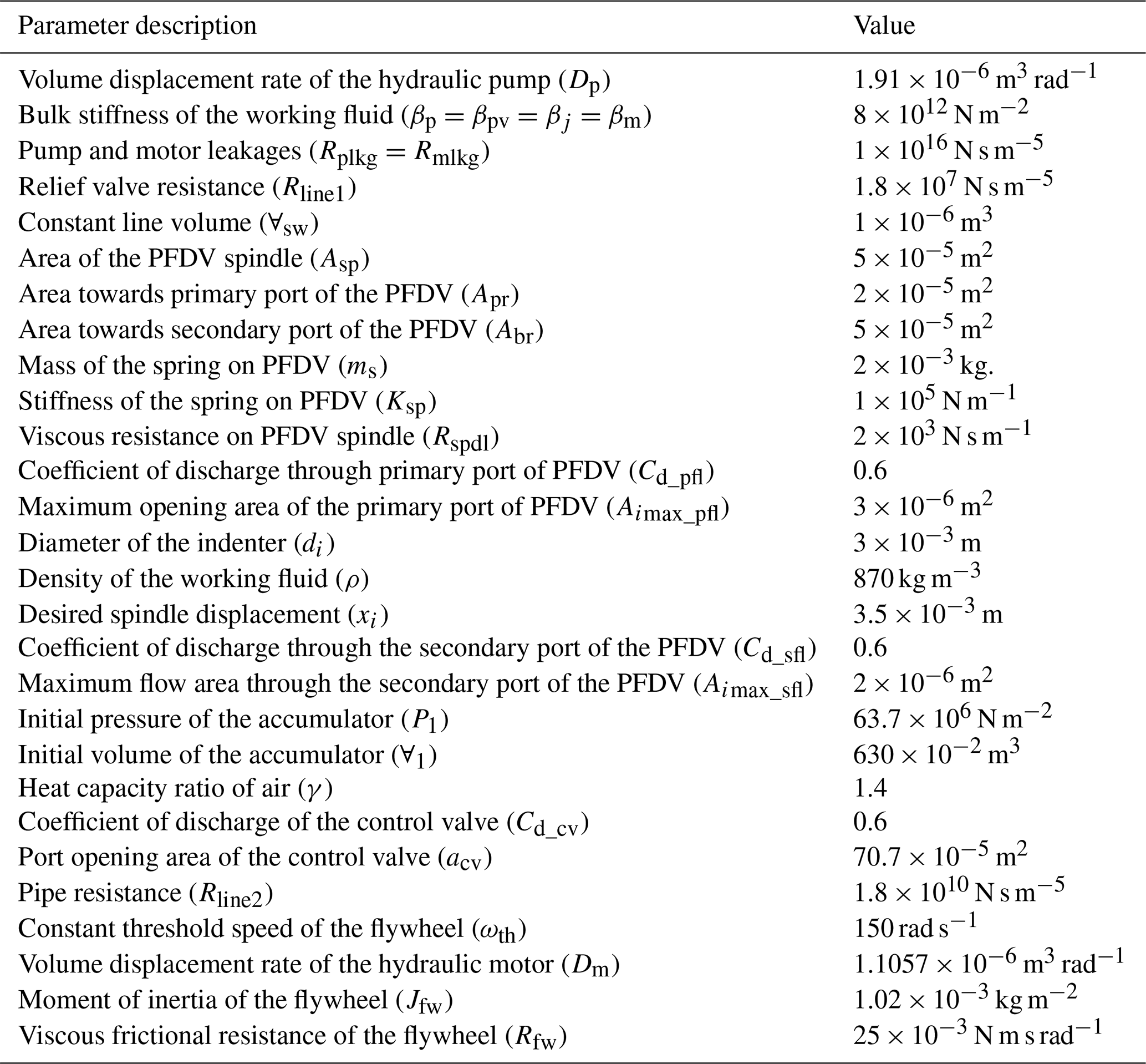
The state equations, i.e., Eqs. (11)–(13), of the open-loop SMHPTSPFDV and the Eqs. (11)–(13) and (20)–(22) of the WTHPTSPFDV are obtained from the bond graph models Figs. 4 and 5, respectively. Thereafter, the same equations are solved in SYMBOLS Shakti software. This software contains different modules, such as the graphical model builder, simulation workbench, control theoretical analysis tool, FDI (fault detection and isolation) model builder, etc. In the present study, the graphical model builder module is used to generate the state equations by modeling the bond graph of the systems, whereas other module, i.e., the simulation workbench is used to simulate the bond graph models. The simulation workbench module is embedded with various integration techniques such as Runge–Kutta–Gill, Runge–Kutta–Fehlberg, Gear's predictor–corrector algorithm, etc., to solve the state equations (Borutzky and Granda, 2002). In this present simulation study, the fifth-order Runge–Kutta–Gill method is used to solve the differential equations. The precision of the simulation is improved by adjusting the step size in time stepping in such a way that the relative truncation error should be lesser. In the present simulation study, the error limit is chosen as . The numerical values of the simulation parameters are presented in Table 1. The values of the parameters related to PFDV are taken from experimentally validated data given in the article by Kumar et al. (2019a, b), and other parameter values are used therein are considered in the present study.
The simulation responses of the SMHPTSPFDV are presented in Figs. 6 and 7, whereas the simulation responses of the WTHPTSPFDV are shown in Fig. 8. Figure 6a shows that the hydraulic pump is operated with a variable speed. The speed of the hydraulic pump (ωp) is varied from 180 to 36 rad s−1. The corresponding pressure at the pump plenum is varied from 5.06 to 1.31 MPa (refer to Fig. 6b). To operate the primary circuit, the desired displacement of the spindle (xi) is taken as m (refer to Fig. 6c). The spindle displacement is the major criterion for whether the flow is passed through the secondary port of the PFDV or not. When the spindle displacement of the PFDV (xspdl) is more than xi, the secondary port of the PFDV is enabled, and hence, it allows the excess flow to pass through it. From Fig. 6c, when time (t) is less than 1.001 s, the spindle displacement is more than the desired displacement, i.e., m; as a result, both ports, i.e., primary and secondary ports, are inactive modes and allows flow through these ports (refer Fig. 6d). In the subsequent time period between 1.001 to 2.001 s, the spindle displacement (xspdl) is lesser than its desired displacement; as a result, only the primary port of the PFDV is enabled, and flow passes through it. At the same time, the secondary port of the PFDV is disabled, and it does not allow the flow to pass through it (refer to Fig. 6d).
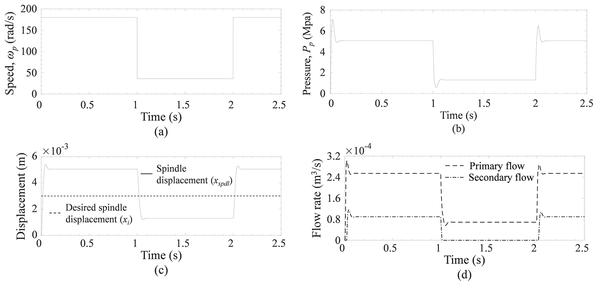
Figure 6(a) Variable speed. (b) Pressure at the pump plenum. (c) Displacement of PFDV spindle. (d) Flow rate through the primary and secondary port of the PFDV.
Similarly, a sinusoidal speed is supplied to the pump, as shown in Fig. 7a. The speed is varied from 20 to 180 rad s−1. The corresponding minimum and maximum pressures at the pump plenum are 0.94 and 5.07 MPa, respectively (refer to Fig. 7b). When the xspdl is less than xi, the secondary port is closed, and no flow passes through it. But when the xspdl is larger than xi, both ports are opened, and then both primary and secondary circuits are in functioning mode (refer to Fig. 7c and d).
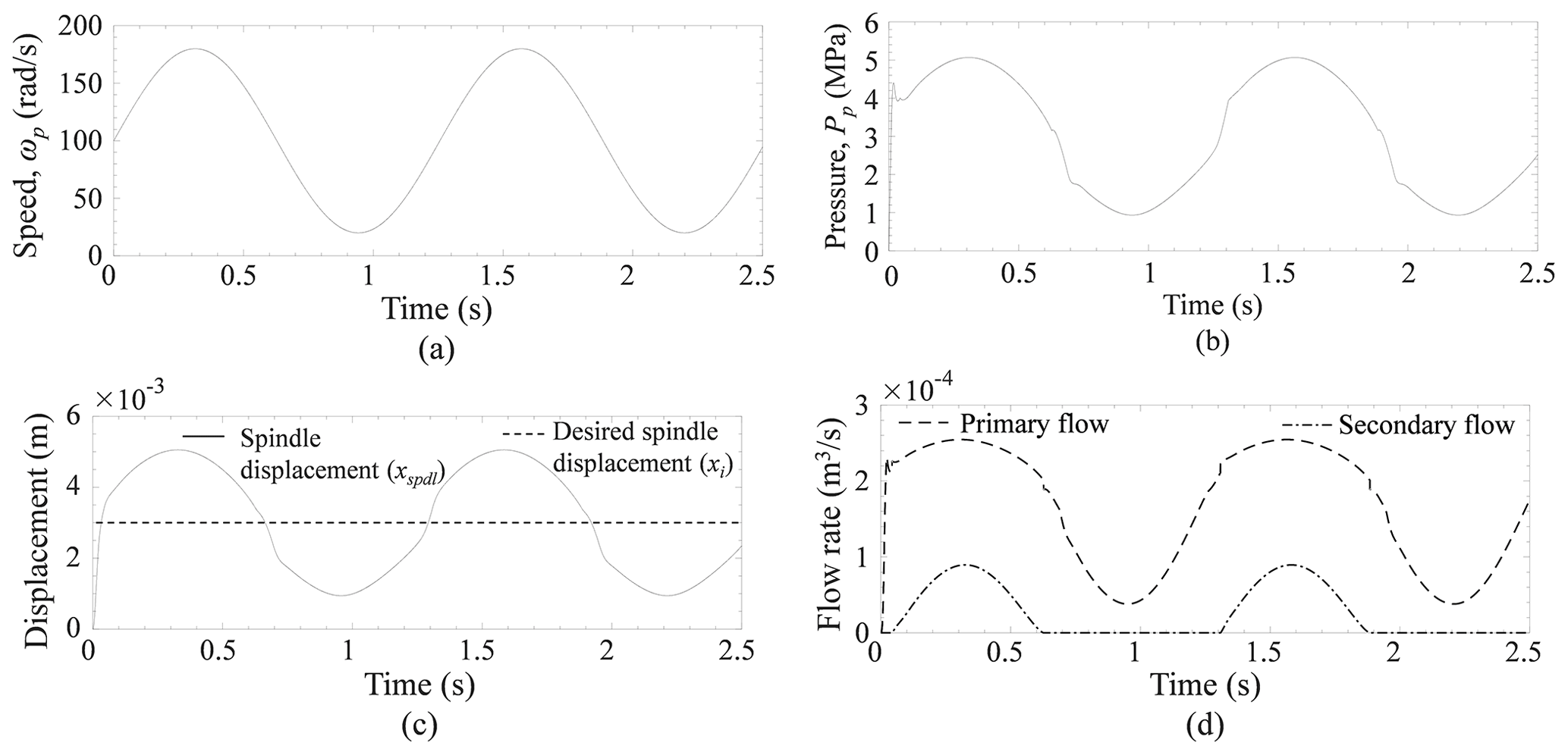
Figure 7(a) Sinusoidal speed. (b) Pressure at pump plenum. (c) Displacement of PFDV spindle. (d) Flow rate through the primary and secondary port of the PFDV.
The responses of the WTHPTSPFDV are presented in Fig. 8. The objective of the stated system is to obtain a stable speed from the flywheel whenever the input speed is of fluctuating manner. Figure 8a shows that the speed of the hydraulic pump (ωp) is varied from 160 to 36 rad s−1, whereas the output speed or the flywheel speed (ωfw) is obtained as stable, and its numerical value is about 150 rad s−1 (refer Fig. 8e). This power hydraulic scheme can be useful for transmitting the power from the turbine rotor to the generator in a wind turbine when a stable power supply is essential against a fluctuating wind speed supply. As the ωp is variable, the supply flow from the hydraulic pump to the PFDV is also variable in nature, and hence, the flow through the primary and secondary port of the PFDV is also unstable in nature. The flow through the primary port of the PFDV (Qpfl) is controlled as per the loading conditions of the system. The spindle displacement of the PFDV is adjustable as per the load of the system to supply a desired flow to the hydraulic motor through the primary port of the PFDV. In this system, the threshold value of the spindle displacement (xi) is about m. This threshold value or the desired value of the spindle displacement is decided as per the loading condition of the system. If the instantaneous spindle displacement (xspdl) is more than the desired spindle displacement (xi) or xspdl≥xi, then the excess spindle displacement helps to enable the secondary flow through the PFDV. The secondary flow is the excess flow at that corresponding load, and it is stored into the accumulator in the secondary flow line. The same situation is observed in time durations t = 0–1, 2–3, and 4–5 s (refer Fig. 8b and c). In a counter-situation, when the pump supply is comparatively low, the spindle displacement (xspdl) of the PFDV is also lower than its desired spindle displacement (xi), i.e., xspdl≤xi. As a result, the pump flow is only passed through the primary port of the PFDV, and hence, there is no flow through the secondary port of the PFDV. The stated situation is observed whenever time durations t = 1–2 and 3–4 s (refer Fig. 8b and c). In these time periods t = 1–2 and 3–4 s, the primary flow of the PFDV is unable to manage the desired flow supply to the hydraulic motor in order to maintain a stable speed of the flywheel. To compensate for the desired flow to the hydraulic motor and to obtain a stable speed of the flywheel, the accumulator starts to discharge and, hence, supplies an additional flow to the hydraulic motor through the secondary flow line (refer Fig. 8e). This secondary flow is controlled by the control valve. The operation of the control valve is controlled by an on/off controller, which receives a signal from the speed sensor of the flywheel. In order to maintain a stable speed of the flywheel, when the supplied flow to the hydraulic motor is less than its desired value, the instantaneous speed of the flywheel is decreased from its threshold speed (ωth), and at that instant, the control valve is enabled and allows flow through it (refer Fig. 8e). The threshold speed of the flywheel (ωth) depends on the loading condition of the system. In this system, the threshold speed of the flywheel is about 150 rad s−1. The control valve is in an open condition during time period t = 1–2 and 3–4 s (refer Fig. 8e). The pump plenum pressure of the system is varied from 10.2 to 7 MPa, whereas the motor plenum pressure is almost constant, and it is about 6.5 MPa.
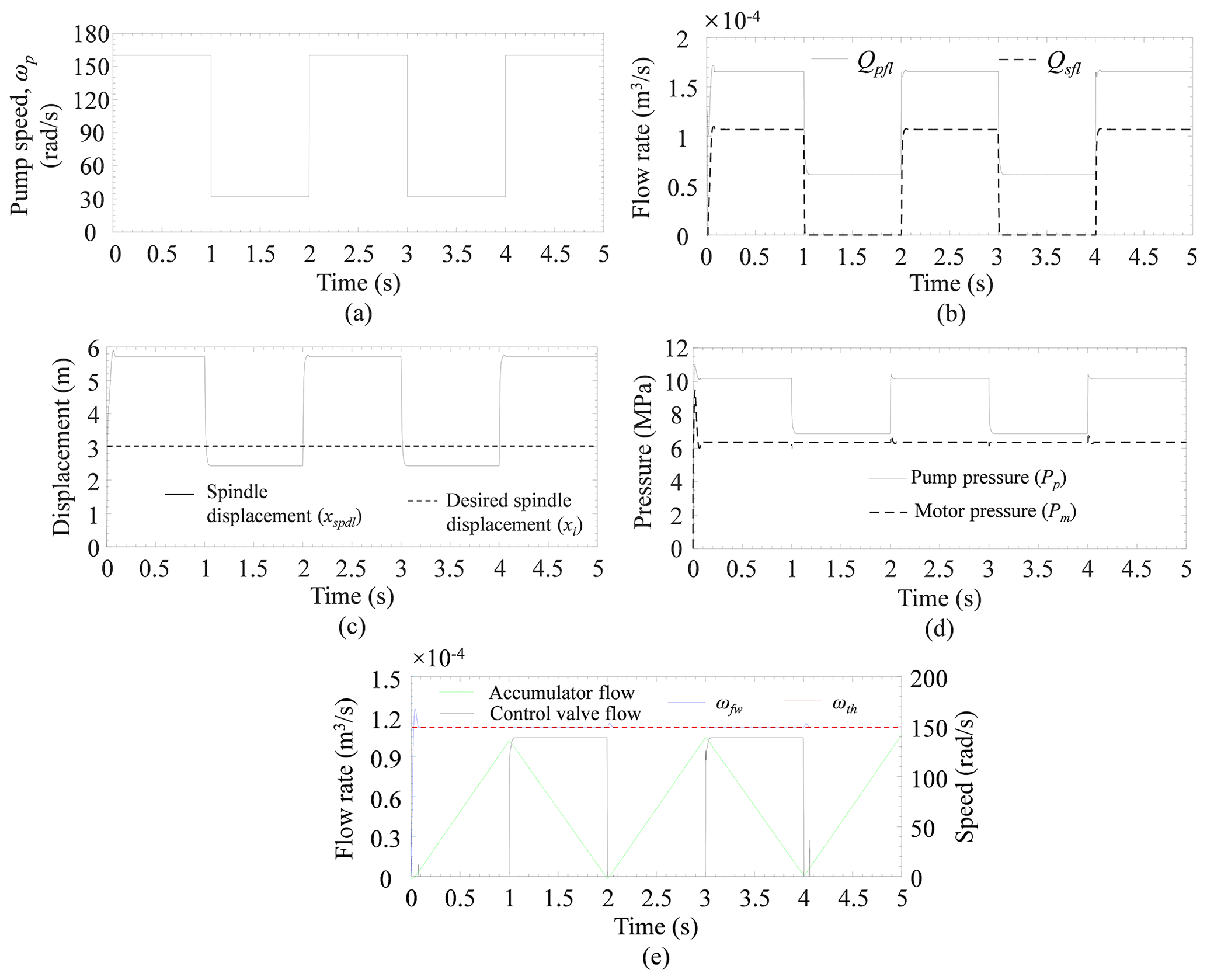
Figure 8(a) Pump speed. (b) Flow rate through primary and secondary port of the PFDV. (c) Spindle displacement of the PFDV. (d) Hydraulic pump and motor plenum pressure. (e) Time response of accumulator flow, control valve flow, and flywheel speed for fixed threshold flywheel speed.
The responses of power and energy loss through the ports of the PFDV are presented in Figs. 9 and 10 for both applications. The energy is dissipated as heat energy, which is associated with pressure head loss. To overcome the head loss, additional power is needed to the system, and it is estimated as a product of flow rate (Q) and the pressure drop across PFDV ports (ΔP) through it. Moreover, the integration of the power loss (Pl) provides the energy loss (El) of the system. The power and energy loss are expressed as follows:
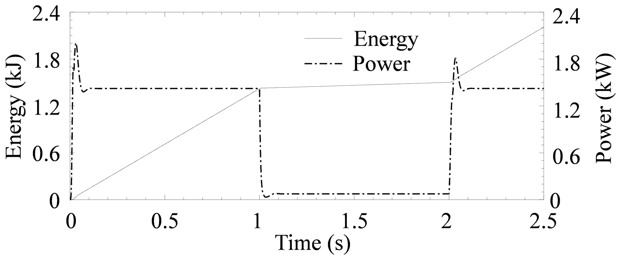
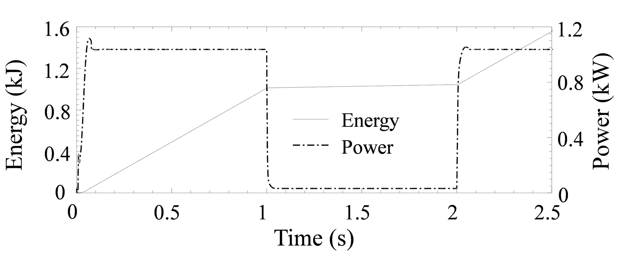
The power loss through the PFDV in both applications is at its maximum when the system is in transition mode, which means during the variation of the input of the system. The power loss through the PFDV is higher when it is connected with dual loads for performing dual functions, i.e., SMHPTSPFDV. The maximum power loss in SMHPTSPFDV is 1.9 kW, and WTHPTSPFDV is almost 1.5 kW. Similarly, the energy loss is also higher when the PFDV is connected with the same system, i.e., SMHPTSPFDV. The energy loss in SMHPTSPFDV is 2.3 kJ, and WTHPTSPFDV is almost 1.2 kJ.
5.1 Influences on energy and power loss in WTHPTSPFDV through PFDV due to the variation in viscous friction resistance
Influences on the power and energy loss through the PFDV, due to the variation in the viscous friction resistance are studied and presented in Fig. 11. From Fig. 11, it can be observed that the energy loss and power loss decreases with the increase in Rfw in WTHPTSPFDV. In Fig. 11a, the energy loss is increased from 1.5 to 1.2 kJ, when Rfw is decreased from 0.04 to 0.025 N m s rad−1, respectively. Similarly, from Fig. 11b, the power loss is decreased from 1.2 to 0.8 kW, when Rfw is increased from 0.04 to 0.025 N m s rad−1, respectively.
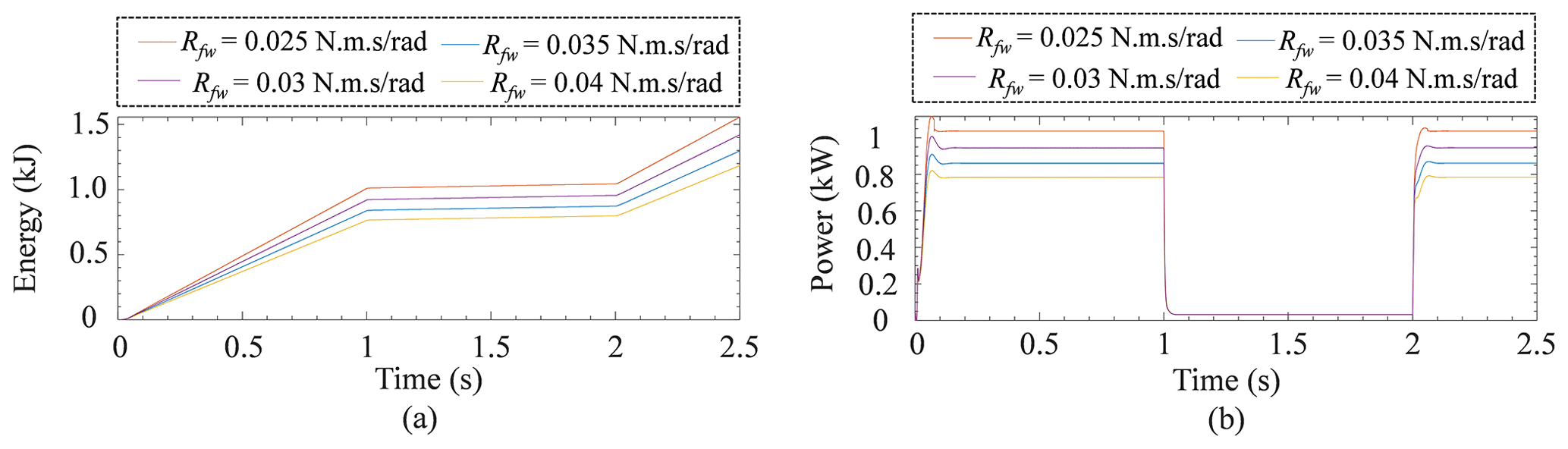
Figure 11Influences on energy and power loss through the PFDV, due to various load in WTHPTSPFDV. (a) Energy loss. (b) Power loss.
5.2 Influences on energy and power loss in SMHPTSPFDV through PFDV due to the variation in load
This section discussed the influence of power and energy loss through the PFDV in SMHPTSPFDV circuit when primary and secondary loads are varied. From Fig. 12a, the energy loss is decreased with the increase in the primary load (Ppl), which has been varied from 1×10⁵ to 1×10⁶ Pa. During the Ppl variation, the secondary load (Psl) is considered to be fixed, i.e., 1×10⁵ Pa. Similarly, at the same conditions, the power loss is analyzed. It is observed that it decreases with the increase in the Ppl (refer Fig. 12b). On the contrary, when Ppl is fixed, and Psl is varied from 1×10⁵ to 1×10⁶ Pa, then it is observed that both energy loss and power loss are decreased with the increase in load.

Figure 12Energy and power loss variation in SMHPTSPFDV system. (a) Energy loss when Psl is fixed and Ppl is varied. (b) Power loss when Psl is fixed and Ppl is varied. (c) Energy loss when Ppl is fixed and Psl is varied. (d) Power loss when Ppl is fixed and Psl is varied.
This article presents a simulation-based work for the performance analysis of three ports-based PFDV. This valve is the key equipment in the power hydraulic system, and it can be used with two different power hydraulic schemes to transmit the power. First, the scheme which is performed has dual functions simultaneously with separate loading conditions, i.e., SMHPTSPFDV, and the second scheme is used to obtain a stable output against a stable demand whenever the input parameter is of a fluctuating nature i.e. WTHPTSPFDV. The prior scheme is mostly used in automobile steering systems with a load-sensing control strategy in the presence of multiple actuators, whereas the latter scheme can be used in wind turbine application to obtain a stable power as the input wind velocity is of a fluctuating nature due to cyclones, storms, etc. This scheme may reduce the probability of loadshedding at the power supply point of the wind turbine with the help of a PFDV, an accumulator, and a control valve. The following findings have been obtained from the present study.
-
The SMHPTSPFDV (refer to Fig. 2) is implemented when it is required to operate dual hydraulic circuits simultaneously with different loading conditions. The stated system successfully divides the pump flow into two different paths in a specified ratio by the use of PFDV. The flow rate ratios through these two paths are adjustable as per the loading conditions.
-
The WTHPTSPFDV (refer to Fig. 3) can be suitable whenever it is required to have a stable output from a variable input to the system. This scheme is successfully operated with the help of a PFDV, an accumulator, and a control valve.
-
The power and energy loss through the PFDV is higher when it is connected with the dual loads for performing dual functions, i.e., SMHPTSPFDV, compared to the other hydraulic drive systems used in wind turbines to obtain stable output, i.e., WTHPTSPFDV.
-
The WTHPTSPFDV can be executed in wind turbine applications to transmit the power from the turbine rotor to the generator. The present work is based on simulation analysis. Therefore, experimental work is required to validate the responses of the system. It may help to improve the credibility and superiority of the proposed schemes.
The datasets generated during and/or analyzed during the current study are available from the corresponding author on reasonable request.
ACM conceived the project and design, decided on the methodology, and supervised. DK performed the simulation work and prepared the draft. OP helped to complete the simulation work and carried out the critical analysis. KK monitored the work and critically reviewed the paper.
The contact author has declared that neither they nor their co-authors have any competing interests.
Publisher’s note: Copernicus Publications remains neutral with regard to jurisdictional claims in published maps and institutional affiliations.
This study has been funded by Birla Institute of Technology, Mesra (grant no. GO/Estb/SMS/2020-21/2262).
This paper was edited by Daniel Condurache and reviewed by two anonymous referees.
Alderson, L. L. and Truesdell, D. E.: Priority flow valve, U.S. Patent 4, 192, 337, Cessna Aircraft Co, 1980.
Borutzky, W.: Bond Graphs for Modelling, Control and Fault Diagnosis of Engineering Systems, Springer, Cham, https://doi.org/10.1007/978-3-319-47434-2, 2017.
Borutzky, W. and Granda, J.: Bond graph based frequency domain sensitivity analysis of multidisciplinary systems, P. I. Mech. Eng. I-J. Sys., 216, 85–99, https://doi.org/10.1243/0959651021541453, 2002.
Chen, X. and Guo, K. H.: Development for generalised multi-axle steering vehicle handling, Int. J. Heavy Veh. Syst., 27, 777–799, https://doi.org/10.1504/IJHVS.2020.112971, 2020.
Cheng, M.: Modelling and Analysis of a Flow Divider Valve, ASME 21st Forum on Fluid Machinery Conference Proceeding, 2, 91–98, https://doi.org/10.1115/FEDSM2009-78120, 2010.
Coskun, G., Kolcuoglu, T., Dogramacı, T., Turkmen, A. C., Celik, C., and Soyhan, H. S.: Analysis of a priority flow control valve with hydraulic system simulation model, J. Braz. Soc. Mech. Sci., 39, 1597–1605, https://doi.org/10.1007/s40430-016-0691-7, 2017.
Darling, J., Tilley, D. G., and Hickson, L. R.: A centralized hydraulic system for passenger cars, P. I. Mech. Eng. D-J. Aut., 213, 425–434, https://doi.org/10.1243/0954407991526982,1999.
Ding, H., Liu, Y., and Zhao, Y.: A new hydraulic synchronous scheme in open-loop control: Load-sensing synchronous control, Meas. Control, 53, 119–125, https://doi.org/10.1177/0020294019896000, 2020.
Fan, Y., Mu, A., and Ma, T.: Study on the application of energy storage system in offshore wind turbine with hydraulic transmission, Energ. Convers. Manage., 110, 338–346, 2016.
Fedoroff, M., Burton, R. T., Schoenau, G. J., and Zhang, Y.: Dynamic and steady-state analysis of an auto-regulator in a flow divider and/or combiner valve, J. Dyn. Syst.-T. ASME, 114, 306–314, 1992.
Giacomelli, M., Padula, F., Simoni, L., and Visioli, A.: Simplified input-output inversion control of a double pendulum overhead crane for residual oscillations reduction, Mechatronics, 56, 37–47, https://doi.org/10.1016/j.mechatronics.2018.10.002, 2018.
Hussain, M. A., Mohd Ali, J., and Khan, M. J. H.: Neural network inverse model control strategy: discrete-time stability analysis for relative order two systems, Abstr. Appl. Anal., 2014, 645982, https://doi.org/10.1155/2014/645982, 2014.
Kumar, S., Dasgupta, K., and Ghoshal, S. K.: Fault diagnosis and prognosis of a hydro-motor drive system using priority valve, J. Braz. Soc. Mech. Sci., 41, 77, https://doi.org/10.1007/s40430-019-1572-7, 2019a.
Kumar, S., Dasgupta, K., Ghoshal, S. K., and Das, J.: Dynamic analysis of a hydro-motor drive system using priority valve, P. I. Mech. Eng. E-J. Pro., 233, 508–525, https://doi.org/10.1177/0954408918770470, 2019b.
Mahato, A. C. and Ghoshal, S. K.: Energy-saving strategies on power hydraulic system: An overview, P. I. Mech. Eng. I-J. Sys., 235, 147–169, https://doi.org/10.1177/0959651820931627, 2021.
Mahato, A. C., Ghoshal, S. K., and Samantaray, A. K.: Influence of locking and passive soft switching on hydraulic circuit efficiency, Simulation, 93, 237–249, https://doi.org/10.1177/0037549716682094, 2017.
Mahato, A. C., Ghoshal, S. K., and Samantaray, A. K.: Reduction of wind turbine power fluctuation by using priority flow divider valve in a hydraulic power transmission, Mech. Mach. Theory, 128, 234–253, https://doi.org/10.1016/j.mechmachtheory.2018.05.019, 2018.
Merzouki, R., Samantaray, A. K., Pathak, P. M., and Ould Bouamama, B.: Intelligent Mechatronic Systems: Modeling, Control and Diagnosis, Springer Science & Business Media, https://doi.org/10.1007/978-1-4471-4628-5, 2013.
Metwally, M., El-Azm, A. A., and El-Sherif, I.: Dynamic and steady-state analysis of split spool flow divider valve, in: Proceedings of the 15th Int. AMME Conference, The Military Technical College, Vol. 29, p. 31, https://doi.org/10.21608/amme.2012.36987, 2012.
Mukherjee, A., Karmakar, R., and Samantaray, A. K.: Bond Graph in Modeling, Simulation and Fault Identification, I.K. International Pvt Ltd., CRC Press, New Delhi, ISBN 81-88237-96-5, 2006.
Samantaray, A. K. and Mukherjee, A.: User's Manual of SYMBOLS Shakti, High-Tech Consultants STEP, Indian Institute of Technology Kharagpur, https://www.researchgate.net/publication/257073655_SYMBOLS_Shakti_User's_Manual (last access: 13 September 2021), 2006.
Tripathi, J. P., Hasan, M., and Ghoshal, S. K.: Real-time model inversion control for speed recovery of hydrostatic drive used in the rotary head of a blasthole drilling machine, J. Braz. Soc. Mech. Sci., 44, 1–15, https://doi.org/10.1007/s40430-021-03347-0, 2022.
Vacca, A. and Cerutti, M.: Analysis and optimization of a two-way valve using response surface methodology, International Journal of Fluid Power, 8, 43–57, https://doi.org/10.1080/14399776.2007.10781285, 2007.
Wang, B., Zha, H., Zhong, G., Li, Q., and Wang, X.: Integrated active steering control strategy for autonomous articulated vehicles, Int. J. Heavy Veh. Syst., 27, 565–599, https://doi.org/10.1504/IJHVS.2020.111262, 2020.
Watton, J.: Fundamentals of Fluid Power Control, 10, Cambridge University Press, New York, https://doi.org/10.1017/CBO9781139175241, 2009.
Wiens, T., Burton, R., Schoenau, G., and Ruan, J.: Optimization and Experimental Verification of a Variable Ratio Flow Divider Valve, International Journal of Fluid Power, 6, 45–53, https://doi.org/10.1080/14399776.2005.10781229, 2005.
Wiens, T. K.: An adjustable-ratio flow dividing hydraulic valve, Doctoral dissertation, University of Saskatchewan, http://hdl.handle.net/10388/etd-08312004-100306 (last access: 12 February 2021), 2004.
- Abstract
- Introduction
- Outline of the hydrostatic power transmission system with PFDV (HPTSPFDV)
- System modeling of the HPTSPFDV
- Results and discussion
- Energy and power loss through the PFDV
- Conclusions
- Data availability
- Author contributions
- Competing interests
- Disclaimer
- Financial support
- Review statement
- References