the Creative Commons Attribution 4.0 License.
the Creative Commons Attribution 4.0 License.
 | 13 May 2022
Optimization and active control of internal gearing power honing process parameters for better gear precision
Bin Yuan
Jiang Han
Xiaoqing Tian
Lian Xia
Optimization and active control of internal gearing power honing (IGPH) process parameters for excellent and stable gear precision were carried out using the engagement theory of a conjugate curved face, the Box–Behnken design of experiments method, and the artificial immune clone selection algorithm (AICSA). Optimization and active control were carried out in four stages. In the first stage, the second-order models of tooth profile deviations were developed considering the nonlinear influence of IGPH process parameters on tooth profile deviations based on the Box–Behnken design. In the second stage, a method for solving the multi-objective optimization of the IGPH process was presented based on building the synthetic tooth profile deviation model, which considered the different weighting factors of different tooth profile deviation indexes. In the third stage, excellent gear precision was obtained by importing the ranges of synthetic tooth profile deviation and parameters into the AICSA. In the fourth stage, based on the optimized process parameters, the active control of IGPH process parameters was realized based on the constant cutting speed on the fixed position of the gear tooth surface. The total gear profile error reached a minimum value at the optimal parameters of 1270.4 rpm for spindle speed, 60 mm min−1 for axis feed velocity, 2.4 µm per oscillation for radial feed velocity, and 2.4 spark-out times. The gear accuracy test results show that the total gear profile error value from the above active control method is more stable and lower than that without active control, indicating that the proposed method is effective.
- Article
(2072 KB) - Full-text XML
- BibTeX
- EndNote


Internal gearing power honing (IGPH) is a gear finishing process via abrasion that can improve gear tooth surface quality; it is thus widely used in the field of advanced automobile gearbox systems. The special mechanism of the IGPH process can form a kind of curved orientation texture and high compressive residual stress on workpiece gear tooth surfaces (Karpuschewski et al., 2008). Moreover, these good tooth surface characteristics can reduce the meshing noise and prolong the service life of gear transmission systems. Compared with the worm wheel gear grinding process, the IGPH process is irreplaceable in stepped gear finishing, and its lower cutting velocity can avoid high thermal load and burns on the tooth surface. However, the gear precision of the IGPH process ranges in the GB4–GB6 level, while the worm wheel gear grinding process can reach the GB4–GB5 level, which is the limitation of the IGPH process. Process parameters have a significant effect on gear precision, and, thus, in this paper, several experiments on the optimization of IGPH process parameters for better and more stable gear precision were carried out.
Recently, many studies have focused on the improvement of gear finishing with abrasive processes. For instance, Teixeira et al. (2019) reported the influence of the grains' characteristics and process parameters on the material removal behavior and gear grinding energy model based on modeling of the normal force. Through the use of high-order topology expression and analysis of the numerical loaded tooth contact area, Ding and Tang (2020) proposed a target grinding flank modeling method to improve the tooth flank geometric topography and loaded contact performance. Furthermore, Giacomo et al. (2019) analyzed the relationship between the thermal damage and gear grinding process parameters on a new dry-grinding machine and found that the gear module and radial feed rate were the most significant factors affecting the thermal damage. Yoshikoto et al. (2018) developed a high-precision, high-efficiency internal gear grinding method by setting a large crossed-axis angle between the grinding wheel spindle and workpiece gear axis and conducted a series of actual grinding experiments to verify the new proposed grinding model.
With the wide application of the IGPH process, several studies were carried out to explore the mechanism and improve the gear tooth surface quality of the IGPH process. By adding three axes' additional motions, i.e., the honing wheel spindle axis, swivel axis, and workpiece spindle axis in the internal gearing power honing machine, Vanquyet and Yuren (2020) built a numerical model of the closed-loop topology modification for the double-crowned and anti-twist gear tooth surfaces and verified the validity of the proposed method. A series of preliminary research works were carried out by our team based on traditional roughness theory and the internal engagement theory of conjugate curved surfaces. For example, Han et al. (2017) performed a contrastive analysis of tooth surface quality between the IGPH process and gear grinding process. So far, the main point of the IGPH process is ensuring the microscopic qualities of the tooth surface. In the present work, therefore, to improve the macroscopic quality of the tooth surface for IGPH gears, three main gear tooth profile errors and four input IGPH process parameters were chosen as the factors and indexes of the optimization experiment. The Box–Behnken design of experiments (DOE) method and artificial immune clone selection algorithm (AICSA) were the main optimization methods used to find the predicted model of gear tooth profile deviations and achieve the best gear precision for the IGPH process. Finally, an active control method was proposed to deal with the unstable gear precision caused by the variable IGPH crossed-axis angle parameter.
Design of experiments (DOE) is an important branch of mathematical statistics which has been widely used to find the influence rule between factors (x0, x1, x2, ..., xn) and responses (y0, y1, y2, ..., yn) in scientific research and industry. Response surface methodology is one of the DOE methods, which was proposed by Box and Wilson in 1951 (Korra et al., 2014). Generally, the purpose of response surface methodology is to find the optimal process through building the approximation surface model. If factors have a linear effect on responses, the approximation surface model between responses and factors can be expressed by the first-order Taylor series expansion:
If there are some nonlinear factors in the system, the first-order Taylor series expansion cannot express the system model accurately, and mostly the system model will be comprised of second-order Taylor series expansion:
where y(x) is the response target function; k is the number of factors; βi, βii, and βij are the influence coefficient of each factor; xi and xj are the values of each factor; and ε is the additive constant.
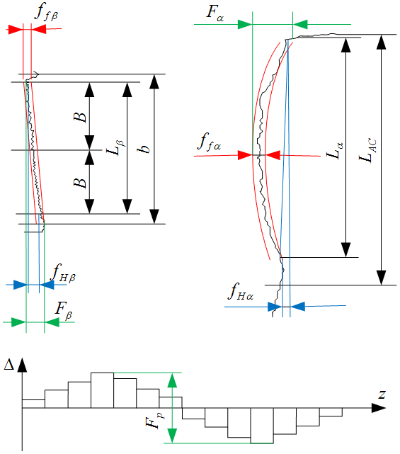
This study aims at achieving minimum gear profile errors. According to the standards of gear accuracy, a high-precision gear will have a good tooth profile accuracy, lead accuracy, and rotation accuracy. In the actual production, the total profile deviation (Fα), the total helix deviation (Fβ), and the total cumulative pitch deviation (FP) embody these three kinds of gear accuracies, as shown in Fig. 1. In this figure, Lβ is the measurement range along tooth longitudinal direction, b is the tooth width, B is the central position of the range, Lα is the measurement range of tooth profile, and LAC is the measuring range of tooth profile. The input parameters of honing process include the spindle speed SW (rpm), the axis feed velocity fz (mm min−1), the radial feed velocity fx (µm per oscillation), and the spark-out times ts. Thus, there are four factors and three responses in this study, and the basic model of the total profile deviation (Fα), the total helix deviation (Fβ), and the total cumulative pitch deviation (FP) were built as in Eq. (3):
The left hand of y(x) is a polynomial which is the approximate value of reality, and the coefficients of the model were estimated by the least-squares method in matrix form. The estimated coefficients of the model depend on the minimum error, and it can be expressed by Eq. (4):
The extreme value of ) can be expressed by Eq. (5):
Equation (5) can be expressed in matrix form by Eq. (6):
and the value of β can be calculated by Eq. (7):
After solving the coefficient of the model, it is necessary to verify the accuracy of the model. The multiple correlation coefficient (R) can be calculated by Eq. (8–10):
where SSY is the total sum of squares for error, SSE is the total sum of squares for regression, SSR is the regression sum of the square, is the mean of response, is the value of the response, and R represents the accuracy of the model; the larger the value, the more accurate.
To screen out the significant factors, the associated F value or p value to the factors can solve this problem:
Such a calculated F value will be compared with the critical value F′. If F>F′, it means that the associated factor is significant, or this factor is insignificant. The other way is to look at the p value of the result, which is calculated by design expert software; if the p value is smaller than 0.05, it indicates the model has 95 % confidence level, which means that the model is statistically significant.
3.1 Pilot experiments
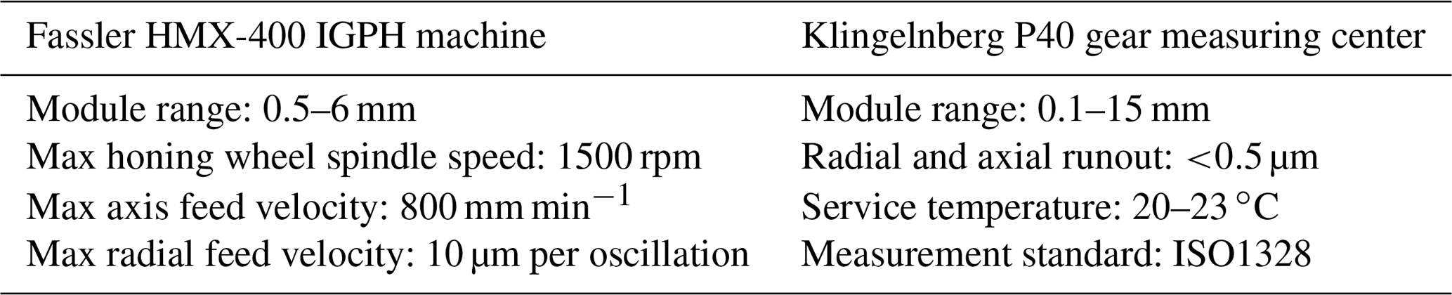
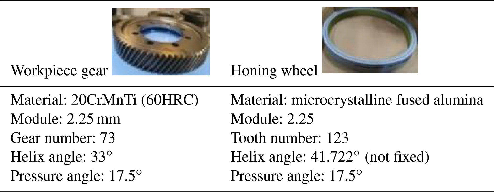
The IGPH experiments were conducted on the HMX-400 IGPH machine. Gear profile errors were measured on the gear measuring center (Klingelnberg P40), as shown in Fig. 1. Table 1 shows the processing parameter range of the IGPH machine and the measuring range of the gear measuring center. Table 2 shows the parameters of the work piece gear and the honing wheel.
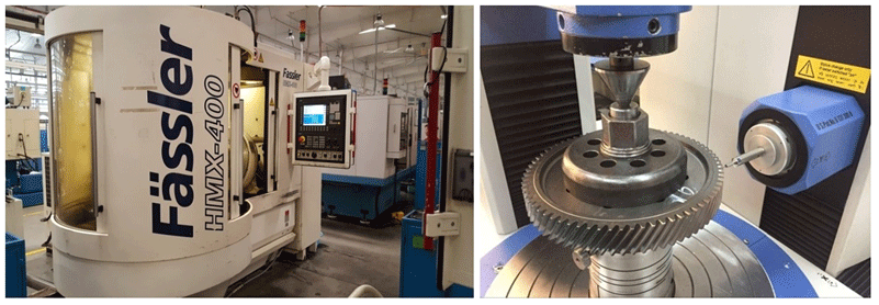
Table 1The main technological parameters of the experiment equipment.
3.2 IGPH experiments based on the Box–Behnken DOE method
British biostatistician Ronald Aylmer Fisher first proposed and established the concept of the DOE (design of experiments) method in the 1920s (Fisher, 1954). The DOE and ANOVA (analysis of variance) methods have been successfully used in agricultural and biological tests since then. A good DOE can exclude most of the interference from non-experimental factors and improve the accuracy of the predicted model and experiment efficiency. Normally, DOE is composed of input factors, unavoidable random factors, and subject and output indexes. In this paper, the input factors are the four input IGPH process parameters; the random factors are the abrasive wear, the cooling and lubrication conditions of machine tools, and so on; the subject is the IGPH process; and the output indexes are the three main gear profile deviations.
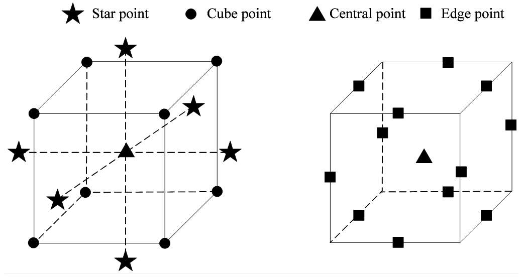
Common response surface methodology (RSM) includes the Box–Behnken design, the central composite design (CCD), the central composite inscribed design (CCI), and the central composite face-centered design (CCF) method. The Box–Behnken design method is a statistical method which is usually used to model the relationship between the factors and responses for s nonlinear system. Compared with the other three methods, the Box–Behnken design method possesses the advantage of a fewer number of tests, and it can avoid exceeding the allowable process parameters. Figure 3 shows the comparison of experiment points between the CCD and Box–Behnken DOE method. It is shown that the star points would exceed the setting process parameter range, and the Box–Behnken DOE method can avoid this problem. Thus, the Box–Behnken DOE method is the most suitable method for this study considering the cost and safety of the experiment.
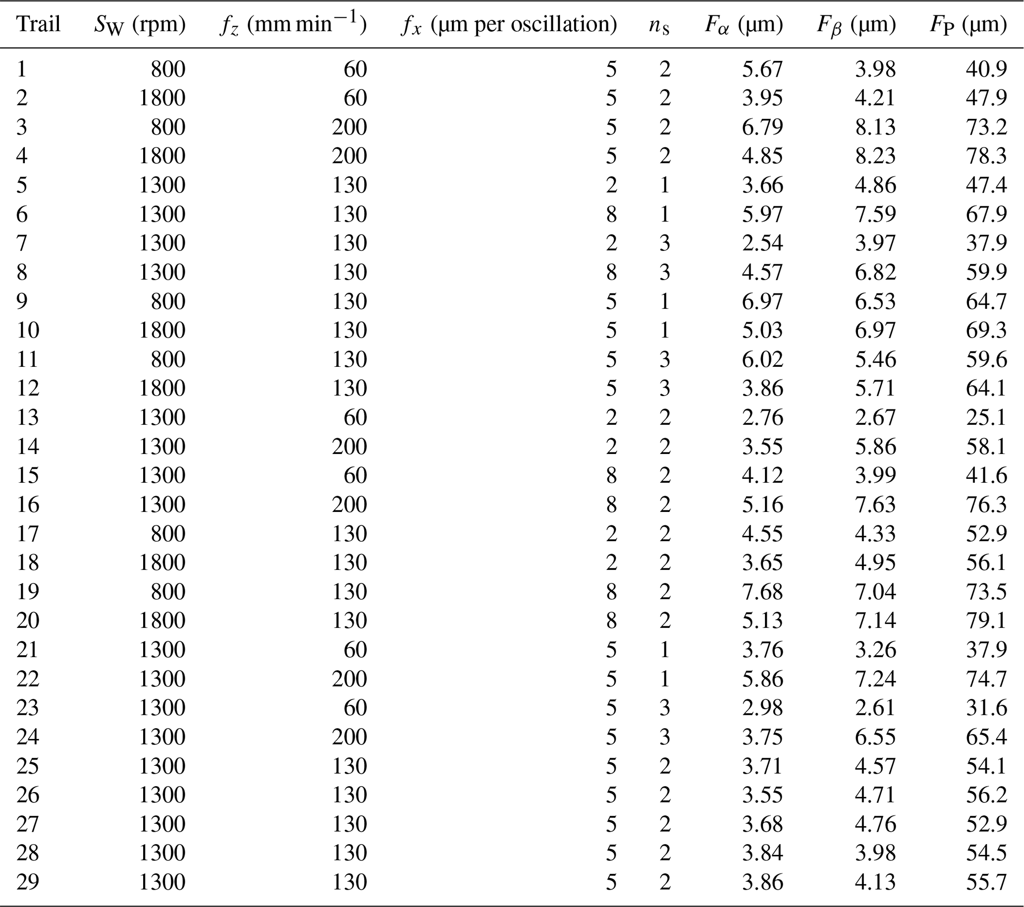
In this study, the main IGPH process parameters were the spindle speed SW (rpm), the axis feed velocity fz (mm min−1), the radial feed velocity fx (µm per oscillation), and the spark-out times ns. The main gear profile deviations were the total profile deviation (Fα), the total helix deviation(Fβ), and the total cumulative pitch deviation (Fp). Based on the principle of the Box–Behnken DOE method and the input IGPH process parameters, the experiment levels were carried out as shown in Table 3. The common spindle speed ranged from 800 to 1800 (rpm), the axis feed velocity ranged from 60 to 200 (mm min−1), the radial feed velocity ranged from 2 to 8 (µm per oscillation), and the spark-out times ranged from 1 to 3.

According to the different combinations of IGPH process parameter levels in Table 3, 29 IGPH processing and gear measuring experiments in total were carried out using the experimental equipment. Figure 4 shows the 29 workpiece gears from 29 IGPH experiments, and Table 4 shows the measured gear profile errors for each IGPH experiment.
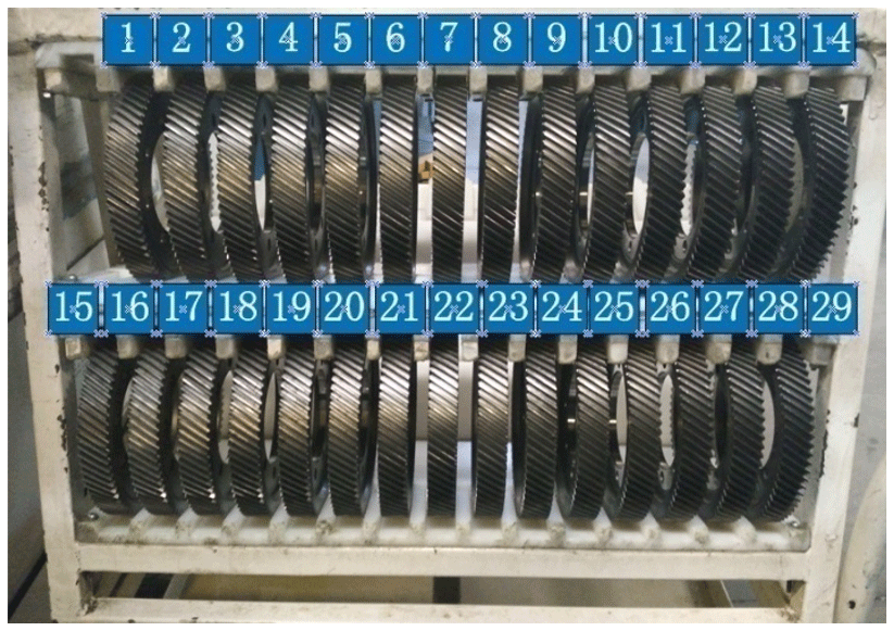
Table 4IGPH experiments and measurement results based on the Box–Behnken DOE method.
After conducting 29 IGPH experiments (Fig. 3), analysis of variance (ANOVA) was carried out to verify the confidence of the gear profile error models based on the response surface methodology (RSM). Equations (12)–(14) show the gear profile error models, and the adjusted R-squared value of the model summary statistics was below 0.9762, 0.9587, and 0.9902; the closer to 1 the adjusted R-squared value was, the more accurate the statistical model.
Figure 5a–c show parts of the response surface of the main gear profile deviation models, while the other two process parameters are set as the common constant, i.e., the radial feed velocity fx=5 (µm per oscillation) and the spark-out times ns=2. Based on these response surface results, the roles each IGPH process parameter plays in influencing the gear profile deviations can be obtained. These three main gear profile deviations decrease with increasing SW before the peak value and then increase with increasing SW because the honing wheel spindle vibration is becoming increasingly more intense with increasing SW. Once a certain value is exceeded, these three main gear profile deviations all increase with increasing fz because the cutting amount per revolution increases. Finally, the comprehensive influence orders were Fα (fx>SW>fz>ns), Fβ (fz>fx>ns>SW), and Fp (fz>fx>ns>SW).

After building the gear profile error models, the optimization studies were carried out based on the AICSA. First, a total gear profile deviation model is needed before the optimization process. Because these three profile deviations have different levels, the results cannot arrive at optimal values when using a simple addition of three profile deviation functions. In this work, a total gear profile deviation model Fall was proposed based on different weighted coefficients of the three gear profile deviation models according to the same precision as from the Chinese Standard No. GBT 10095.1-2008.
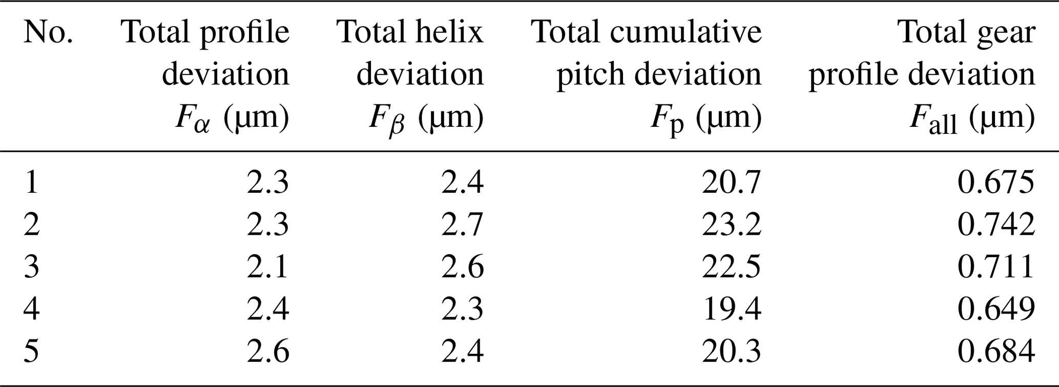
AICSA is a learning algorithm based on the artificial immunity system which performs the autoimmune mechanism of antigen and antibody combination. The AICSA optimization procedure was executed using MATLAB in a Windows operating system, and the optimization process started with a population number of 40, a scale of 10 antibody libraries, and an inhibitory factor of 0.5 that evolved up to 500 iterations. The flowchart and calculation processes of the optimization are shown in Fig. 6. The optimization line stabilized after 75 iterations. The optimal combination of IGPH process parameters based on the AICSA method is shown in Table 5. The comparison experiment of IGPH process between the optimization IGPH process parameters and actual production experience parameters was carried out. Table 6 shows the repeated IGPH process based on the optimization IGPH process parameters, and the result shows that the total profile deviation Fα is approximately flat, and the total helix deviation (Fβ) and the total cumulative pitch deviation (Fp) reduced 39.5 % and 59.5 % compared with the original parameters, which achieved the target of improving the gear precision.
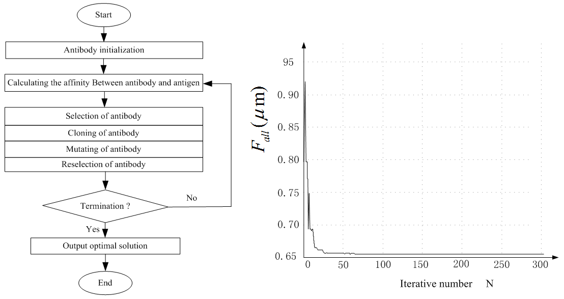
Table 5The optimal combination of IGPH process parameters based on the AICSA method.
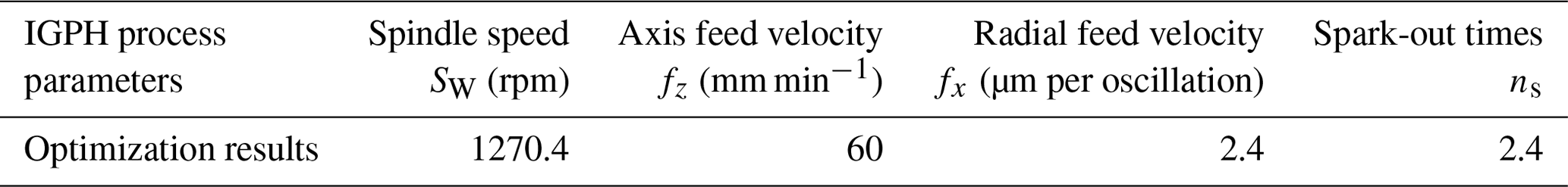
Table 6Five repeated IGPH experimental results based on the optimization process parameters.
In the IGPH process, the tooth profile precision of the honing wheel would be reduced with increasing abrasive wear; therefore, a low-precision honing wheel could increase the rejection rate of workpiece gears. Thus, when a certain amount of a workpiece gear is honed or the radial force and torque of a honing wheel are changed abnormally, it is necessary to use a diamond dressing tool to dress the worn honing wheel during the dressing process. Changing the helix angle of the honing wheel is usually carried out to increase the repair number and service life of the honing wheel. The crossed-axis angle between the honing wheel and workpiece gear also changes when honing various batches of workpiece gears. However, such a change of crossed-axis angle could influence the stability of IGPH process quality. Different IGPH process parameters finally reflect the relative velocity between the honing wheel and the workpiece gear tooth surface. Thus, the relationship between the honing relative velocity, crossed-axis angle, and IGPH spindle speed was built and analyzed in this paper. Machine operators just need to input a suitable honing speed parameter and the basic parameters of workpiece gear and honing wheel, and the rotation speed of the workpiece gear or honing wheel that is needed for the numerical control program can be obtained by the active control algorithm.

Figure 7The coordinate systems of the IGPH machine and the relative velocity on the contact point.
Figure 7a shows the coordinate system of the IGPH process built through analyzing the structure of the IGPH machine and the motion relationship between the honing wheel and the workpiece gear, whereby SO () and ) are the fixed coordinate systems of the workpiece gear and honing wheel, which can be viewed as the initial position of the meshing movement between the workpiece gear and the honing wheel; S1() and S2() are the following rotation coordinate systems of the workpiece gear and honing wheel; a is the center distance between the workpiece gear and honing wheel; φ1 and φ2 are the rotation angle of the workpiece gear and honing wheel; w1 and w2 are the angular velocities of the workpiece gear and honing wheel; and Σ is the crossed-axis angle between the workpiece axis and honing wheel axis. At a certain moment, the teeth surface of the workpiece gear and honing wheel come into a random point M, as shown in Fig. 7b, where is the linear velocity vector of point M on the workpiece gear tooth surface, and is the velocity of point M on the honing wheel tooth surface. Thus, the relative velocity between the honing wheel abrasive and the workpiece gear tooth surface v12 can be shown as Eq. (16) in the coordinate system S).
where is the angular velocity vector of the workpiece gear and is the angular velocity vector of the honing wheel in the coordinate system SO(), and and are the position vector of contact points on the workpiece gear tooth surface and honing wheel tooth surface in the coordinate system SO(). The final calculated value of the relative velocity v12 can be expressed as Eq. (17).
For the convenience of calculation, the relationship between the relative velocity value v12(M0) of point M0 and the spindle speed value (SW) of the workpiece gear at a certain crossed-axis angle (Σ) can be obtained as Eq. (18):
where i12 is the transmission ratio between the workpiece gear and honing wheel.
In Sect. 4, the optimized spindle speed (SW=1270 rpm) was obtained at the crossed-axis angle (Σ=8.722∘), and the relative velocity value at point M0 can be calculated (v12op=2650 mm s−1) at this fixed crossed-axis angle. Based on the relationship between the relative velocity value v12(M0) of point M0 and the spindle speed value (SW) of the workpiece gear at a certain crossed-axis angle (Σ), the adaptable active control of the spindle speed value (SW) can be realized at different crossed-axis angles. Figure 8 shows the active control matched the curve of spindle speed value (SW) with the change of the crossed-axis angle (Σ) from 0 to 20∘. It can be seen that the spindle speed (SW) of the workpiece gear is 8328.8077 rpm which can be translated to the spindle speed of the honing wheel, SH=4943.1135 rpm. But the maximum honing wheel spindle speed is 1500 rpm, which cannot support the needed spindle speed; thus, when choosing the initial design parameters of the honing wheel, low-speed crossed-axis angle zones need to be considered as an important effect factor.
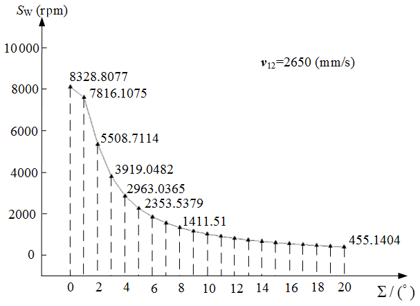
Figure 8Rotation speed of the workpiece gear versus the crossed-axis angle for stable relative velocity.
To verify the effect of this active control method, IGPH experiments were carried out. When the crossed-axis angle arrived at 9.745, 11.745, and 13.745∘, if using the method of keeping the stable honing velocity, the workpiece spindle speed should be suitable for the crossed-axis angle; the adaptive honing wheel spindle speed was 669.1476 rpm, 537.2859 rpm, and 443.5825 rpm. Table 7 shows the results of the gear profile errors based on the active control method.
Table 7The gear profile error results of IGPH experiments based on the active control method.
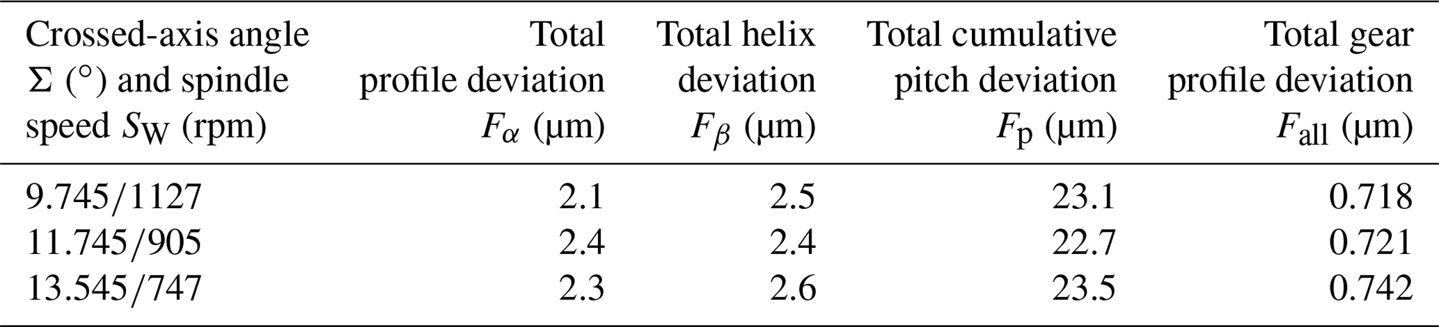
Table 8The gear profile error results of IGPH experiments without the active control method.

The stable spindle speed of 1450 rpm was used when the crossed-axis angle was changing. The results of the gear profile errors are shown in Table 8. It can be seen that the total gear profile error value from the active control method is more stable and lower than that without the active control method. In addition, a lower spindle speed is needed for the IGPH process when the crossed-axis angle is used, which has the advantage of reducing the power consumption and production cost.
In order to improve the machining precision and stability for IGPH gear, this paper proposed a theoretical and experimental strategy for IGPH process parameter optimization. Simultaneously, the research results of this paper have an important theoretical basis and engineering application value to guide the development of the gear finishing process. The following conclusions are drawn from the experimental results:
-
The influences of the input IGPH parameters on the gear profile deviation were obtained based on the Box–Behnken DOE method through 29 IGPH experiments. The comprehensive influence orders were Fα(fx>SW>fz>ns), Fβ(fz>fx>ns>SW), and Fp (fz>fx>ns>SW), which could provide a theoretical basis for the improvement of gear honing quality.
-
A novel total gear profile deviation modeling method was presented considering different weight coefficients on each IGPH process parameter, which could give a new method for multi-objective optimization for the gear honing process.
-
An active control method of IGPH parameters was proposed for stable relative velocity to solve the problem of the crossed-axis angle changing throughout the total life cycle, which could give the suitable IGPH process parameters and honing wheel basic parameters for different situations.
All the data used in this paper can be obtained from the corresponding author upon request.
BY and LX carried out the research on the algorithm and experiment of the paper, and JH and XT provided the experiment conditions.
The contact author has declared that neither they nor their co-authors have any competing interests.
Publisher's note: Copernicus Publications remains neutral with regard to jurisdictional claims in published maps and institutional affiliations.
The authors would like to thank the doctoral initiation fund project of Anhui Jianzhu University (grant no. 2018QD42), the National Natural Science Foundation of China (grant nos. 51575154 and 51875161), the National Science and Technology Major Project (grant no. 2013ZX04002051), and the Fundamental Research Funds for the Central Universities (grant no. CHD300102252507) for supporting this research financially.
This research has been supported by the Anhui Jianzhu University (grant no. 2018QD42), the National Natural Science Foundation of China (grant no. 51575154), and the National Major Science and Technology Projects of China (grant no. 2013ZX04002051).
This paper was edited by Jeong Hoon Ko and reviewed by Zwolak Prof. Jan and one anonymous referee.
Ding, H. and Tang, J.: Machine-tool settings driven high-order topology optimization to grindingtooth flank by considering loaded tooth contact pattern for spiral bevelgears, Int. J. Mech. Sci., 172, 105397, https://doi.org/10.1016/j.ijmecsci.2019.105397, 2020.
Fisher, R. A.: Statistical Methods for Research Workers, Protoplasma, 23, 282, https://doi.org/10.1007/BF01603396, 1954.
Giacomo, G., Flavia, L., and Alessandro, F.: The effect of radial infeed on surface integrity in dry generating gear grinding for industrial production of automotive transmission gears, J. Manuf. Process., 45, 234–241, https://doi.org/10.1016/j.jmapro.2019.07.006, 2019,
Han, J., Yuan, B., Wang, D., Sun, C., and Xia, L.: Formation mechanism study on tooth surface of two gear finishing processes: combined theoretical and experimental approaches, J. Braz. Soc. Mech. Sci., 39, 5159–5170, https://doi.org/10.1007/s40430-017-0872-z, 2017.
Karpuschewski, B., Knoche, H. J., and Hipke, M.: Gear finishing by abrasive processes, J. CIRP Ann.-Manuf. Techn., 57, 621–640, https://doi.org/10.1016/j.cirp.2008.09.002, 2008.
Korra, N. N., Vasudevan, M., and Balasubramanian, K. R.: Multi-objective optimization of activated tungsten inert gas welding of duplex stainless steel using response surface methodology, Int. J. Adv. Manuf. Tech., 77, 67–81, https://doi.org/10.1007/s00170-014-6426-y, 2014.
Teixeira, P. D. O., Brecher, C., and Loepenhaus, C.: Discretization of the contact conditions considering the grain engagement for generating gear grinding, J. Forschung im Ingenieurwesen, 83, 793–800, https://doi.org/10.1007/s10010-019-00351-8, 2019.
Vanquyet, T. and Yuren, W: A novel method for closed-loop topology modification of helical gears using internal-meshing gear honing, Mech. Mach. Theory, 145, 103691, https://doi.org/10.1016/j.mechmachtheory.2019.103691, 2020.
Yoshikoto, Y., Masaharu, K., and Masashi O.: Grinding of internal gears by setting a large crossed-axes angle using a barrel-shaped grinding wheel, J. Precision Engineering, 52, 384–391, https://doi.org/10.1016/j.precisioneng.2018.01.010, 2018.
- Abstract
- Introduction
- Basic gear profile error model
- Experimental work
- Mathematical model
- Optimization
- Active control of IGPH process parameters focuses on different crossed-axis angles
- Conclusion
- Data availability
- Author contributions
- Competing interests
- Disclaimer
- Acknowledgements
- Financial support
- Review statement
- References