the Creative Commons Attribution 4.0 License.
the Creative Commons Attribution 4.0 License.
 | 13 May 2022
A 2 degrees of freedom united propulsive mechanism for amphibious function inspired by frog's hindlimb
Yucheng Tang
Xiaolong Yang
Xiaojin Zhu
Shichao Zhou
Wenbin Zha
Yuxin Sun
Amphibious species of frogs are notable candidates to mimic for amphibious robotic design, as their swimming and sprawling locomotion is generated by the united propulsive mechanisms in which the hindlimbs play the dominant role. Although the propulsive system of frogs is not as complex as other amphibians, it is still difficult to employ the propulsive mechanism in robotic design due to the numerous degrees of freedom (DoF). This paper proposes a novel united propulsive mechanism to acquire the amphibious function inspired by the frog's hindlimb. The mechanism is a hybrid design combining a planar six-bar linkage, which is designed based on homotopy continuation and a spatial four-bar linkage. The DoF of the hindlimb-like mechanism are dramatically decreased to 2, with 1 each in the two sub-chains. Forward analysis is conducted to find the pose of the foot when two actuations are input. The improved analysis based on the geometrical features overcomes the multiplicity from the numerical computation. The inverse kinematic analysis is conducted to find the rotation of the input with a given pose of the foot. The aquatic function of the united propulsive mechanism is demonstrated based on the blade element theory, where the rotational speed and the projected area of the foot are fully active. The terrestrial function of the propulsive mechanism is validated with a specific gait.
- Article
(1969 KB) - Full-text XML
- BibTeX
- EndNote


Inspired from the amphibians, which have an excellent adaptability to both terrestrial and aquatic environments, the demand for the amphibious function of robots has interested more researchers in recent years. Due to the multiple modes of locomotion, there are significant challenges in the robot design, especially in the propulsive mechanism for stable, robust, and highly efficient propulsion in both water and on land. Versatile kinds of propulsive mechanisms have been reported with amphibious capability which can be divided into the following two categories: the separated propulsive mechanism and the united propulsive mechanism.
The separated propulsive mechanism has been widely implemented in salamander-like robots (Crespi et al., 2013; Ijspeert et al., 2007), Pleurobot (Nyakatura et al., 2019; Karakasiliotis et al., 2016) and the quadruped amphibious mechanism (Guo et al., 2018; Xing et al., 2019). A large number of actuators are necessary for driving the two different mechanisms; moreover, the control strategies are complex for activating motors in specified sequences.
On the contrary to the separated propulsive mechanism, the united propulsive mechanism has fewer actuators, as both their terrestrial mode and aquatic mode share the identical propulsive mechanism. Researchers have validated this kind of mechanism, where deformable wheels and transformable flipper legs have been designed (Liang et al., 2012; Zhang et al., 2016; Huang et al., 2017; Dey et al., 2013; Kim et al., 2020). Further categories of simplification have been found in the literature, using the water and ground running mechanism inspired mainly from lizards (Floyd et al., 2006; Kim et al., 2017; Park and Sitti, 2009; Floyd and Sitti, 2008; Kim et al., 2016) or ducks (Kashem et al., 2019). However, most of the designed mechanisms in the literature concentrated on the leg locomotion, while the feet are passively actuated, which lowers the efficiency of amphibious locomotion compared to that of the animals used as a template. Another method is adding another actuator onto the feet which increases the inertia of the feet and complicates the waterproof scheme.
Frogs are one of the most interesting amphibians and have the capability for agile swimming and stable sprawling with a low center of mass. Compared to other amphibians, the spine motion of frogs is not drastic for generating the undulation motion, while the motions of the tails are apparently not mentioned. This feature to reduce the actuating part of the amphibious species of frogs makes them a suitable template for designing amphibious robots. Some work has successively proved their mechanism, which mimics the swimming locomotion of frogs (Fan et al., 2020; Pandey et al., 2013; Tang et al., 2017). The various types of propulsive mechanisms reported in the previous study simplify the hindlimbs driven by the spatial muscular–skeletal system as a planar mechanism combined with webbed-feet-like mechanism. This strategy is insufficient in the terrestrial locomotion of frogs as in the sprawling gait of walking frogs, as the laterally placed hindlimbs have the vertical retraction (Reynaga et al., 2018; Collings et al., 2019). Therefore, the propulsion mechanism for the frog's sprawling requires a three-dimensional motion which is not satisfactorily met with current designs.
The aim of this study is to design a novel propulsive mechanism to mimic the hindlimbs of frogs which can be employed in an amphibious robot. The degrees of freedom (DoF) of the mechanism are minimized by using the closed-loop mechanism when the amphibious function can be acquired. We describe the details of the 2 DoF hindlimb mechanism in Sect. 2. The kinematic and the inverse kinematic analysis of the hybrid spatial mechanism are discussed in Sect. 3. Following that is the design of the six-bar linkage mechanism based on homotopy continuation in Sect. 4. The applications of the designed mechanism for the swimming and sprawling function are demonstrated in Sect. 5.1 and 5.2, respectively. Finally, the conclusion is discussed in Sect. 6.
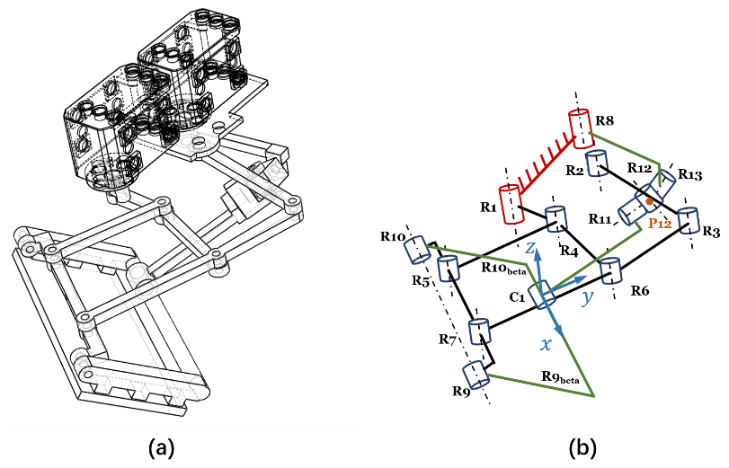
Instead of employing serial mechanisms to mimic the hindlimb of a frog, where plenty of separated actuators are needed, the proposed spatial mechanism, as shown in Fig. 1, is a hybrid mechanism composed of a planar six-bar linkage mechanism and an RSCR (revolute–spherical–cylindrical–revolute) linkage mechanism. The six-bar linkage is configured with seven pivot joints R1–R7, where the rotation axes are parallel to each other. In the spatial four-bar linkage, three connected pivot joints R11–R13 formed as a spherical joint, and the center is P12. The rotation axis of the pivot joint R8 is parallel to the rotation axes in the planar six-bar linkage. A closed-loop is formed as the two mechanisms are connected at the pivot joints R9 and R10, which are in the rigid body of the link R5R7. Hence, the output motion of the foot (R9R10R9betaR10beta) is determined by the planar motion of the link R9R10 and the rotation of the R9betaR10beta about axis R9R10, as shown in Fig. 1b. Pivot joints R1 and R8 are selected as the actuators for providing the input movement. We focus on the foot formed by the points R9R10R10beta and R9beta as the working platform which is connected by the two sub-chains.
Mobility is defined as the number of independent coordinates needed to define the configuration of the kinematic chain or the mechanism. We employ the screw theory to analyze the DoF of the kinematic in this work. The kinematic screw coordinates of sub-chain 1 are selected as follows:
The reciprocal screw coordinates of S1 are as follows:
Similarly, the kinematic screw coordinates of the second sub-chain are selected as follows:
The constraint coordinates of the working platform are . Therefore, the kinematic screw coordinates of the working platform Sf are as follows:
The foot has 2 DoF as dim(Sf)=2, which are fully actuated by the actuators from the two sub-chains. The motion of the foot can be dominated by the motion of two actuated joints as its mobility is 2. The two actuators are selected as the pivot joint R1 and R8, denoted in red in Fig. 1b, while two motors are demonstrated in Fig. 1a. This design decreases the payload on the foot caused by actuators and benefits the waterproofing as the actuators can be sealed and placed inside of the robot body.
3.1 The forward kinematic analysis of the spatial linkage mechanism
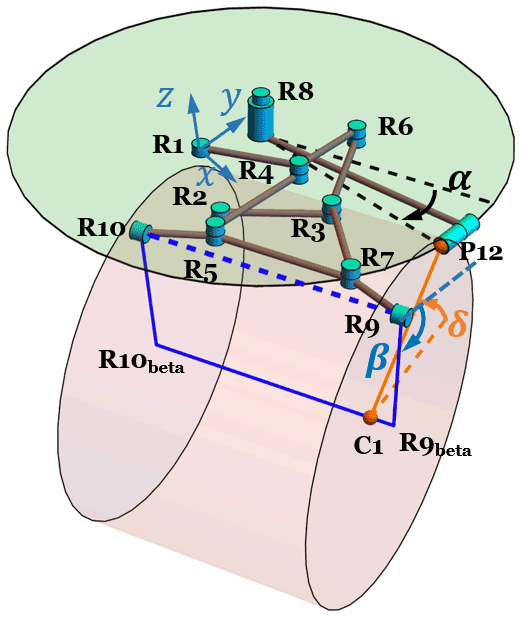
The forward kinematic analysis is concerned with finding the pose of the end-effector for given inputs. In this study, the pose of the end-effector R9R10R9betaR10beta can be calculated with the given input in the pivot joint R1 and R8. The output movement of the link R9R10 can be found, as derived in Sect. 4. The angle φ12 is the rotation of R9betaR10beta about R9R10 and is determined by finding one point in the line R9betaR10beta, considering that R9betaR10beta is parallel to R9R10. Denoting N12 as the point in the line R9R10 and N12⊥R9R10, N12beta is in the center of the cylinder joint C1, as shown in Fig. 2, which is relevant to N12. Since R9R10⊥ P12N12beta, and R9R10⊥P12N12, R9R10 is perpendicular to N12N12beta.

For the convenience in the calculation of finding N12beta, we define RotAB(P,φ) as the position of the point P′, which is where the point P rotates about the vector AB, with angles φ, ABCP∈R3, and φ∈R. NAB(P) is denoted as the foot of perpendicular of AB which passes point P. UAB is the unit vector of AB. NAB(P) is derived as follows:
can be calculated as follows:
where, in the following:
The position of R9beta, with the input α, can be acquired as follows:
where φ12 can be calculated from the triangle formed by the point P12, N12, and N12beta in the following:
In this mechanism design, we make R9betaR10beta below R12; thus, the rotation about R10R9 from N12R12 to N12N12beta is always clockwise, which explains the negative sign in, and the range of, φ12. The position of N12beta is calculated with the pose of the end-effector R9R10R9betaR10beta, which are found with the input rotation in pivot R1 and R8.
3.2 The inverse kinematic analysis of the spatial linkage mechanism
Different from the forward kinematic analysis, the inverse kinematic analysis aims to find the unknown input actuation with a given pose of the end-effector. As demonstrated in Fig. 3, the point C1 is the center of the cylinder joint which is unknown. The z axis in the local frame C1xyz is parallel to the z axis in the frame R1xyz, and the unit vector representing the z axis in the local frame C1xyz is . P12 is the intersection of two circles. The centers of these two circles are C1 and R8, where the radius is |C1P12| and |R8P12|, respectively. Denoting the length of |R10betaC1| as d, the rotation of C1P12, starting from C1y as δ and the input rotation in pivot joint R8, is α. In the circle with the center C1, P12 is written as follows:
In Eq. (15), the following applies:
where , .
In the circle with the center R8, P12 can be calculated as follows:
The variables can be solved from the equation below as follows:
The boundaries of the variables α, , and d are set according to the configuration of the spatial linkage mechanism shown in Fig. 3, which restricts the number of the solution of the Eq. (19) to 1.
The synthesized design of the planar linkage mechanism is characterized by three categories, such as synthesis of the function generator, synthesis of the path generation, and synthesis of the body guidance (Sommese and Wampler, 2005). The objective of the synthesized design of a function generator concentrated on the specific position of the output link with respect to the set of positions of the input link. In the scenario of the application of a path generator, a certain point in the linkage tracks a specified path consisting of several points. Different from the other two cases, both the position and orientation of a rigid link in the whole linkage mechanism are prescribed in a body guidance problem.
The solutions of the synthesized design of the linkage for the purposes mentioned above are generally hard to find, as the order of multivariate complex polynomial systems represented by the isotropic coordinates and their conjugates are fairly high. The homotopy continuation method works perfectly as a robust method where there is no other numerical method to acquire all the possible solutions in many applications of synthesized design, including the all the cases of the function generator, path generation, and body guidance (Plecnik and McCarthy, 2016a, b, c; Plecnik et al., 2014).
Considering that the four-bar linkages have a limited design parameter when numerically solving of the eight-bar linkage requires much more computational cost, we select a six-bar linkage constrained by the 7R loop, shown in Fig. 4, as the potential design for the planar part in the spatial mechanism. The design is the category of the body guidance design, as both the behaviors of the position of R5 and the orientation of the rigid link R5R7 are required to meet the function of the foot.
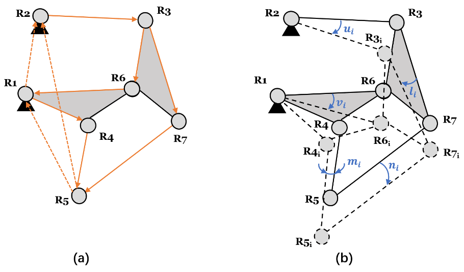
Figure 4(a) The synthesis loops of the six-bar linkage and (b) the related linkage configurations with rotation ui.
The six-bar linkage mechanism is illustrated in Fig. 4, where denotes the pivot joints and represents the position with the rotation applied in this planar mechanism. The orientations of the links R2R3, R1R6(R1R4R4R6), R3R6(R3R7R6R7), R4R5, and R5R7 are conducted by the complex rotation operators ui, vi, li, mi, and ni, respectively. is derived, as follows, with respect to these complex rotation operators and the link R1R2 is treated as the ground link. The synthesis loop equations are written, as follows, where the overbar denotes the complex conjugate and . The isotropic coordinates keep the same as the initial configuration when i=1.
The pairs of the complex conjugate representing the orientation of the rigid links yield the normalization condition in Eq. (23).
The unknown variables are presented as follows:
The variables in the polynomial system (20)–(24) are and and the design parameters are presented in Table 1, when R7 = 5–i. For i = 1–4, ni is set relatively small for the translational motion for the terrestrial locomotion, when n5 is set for guaranteeing the rotation for aquatic locomotion. ni=1–4 is not chosen as zero for the convenience of the convergence in numerical computation. In total, 128 conjugate results are found among 1320 results. The solutions are acquired by using Bertini software (Bates et al., 2013), which used 3835 min on 32 processors working at 3.5 GHz.
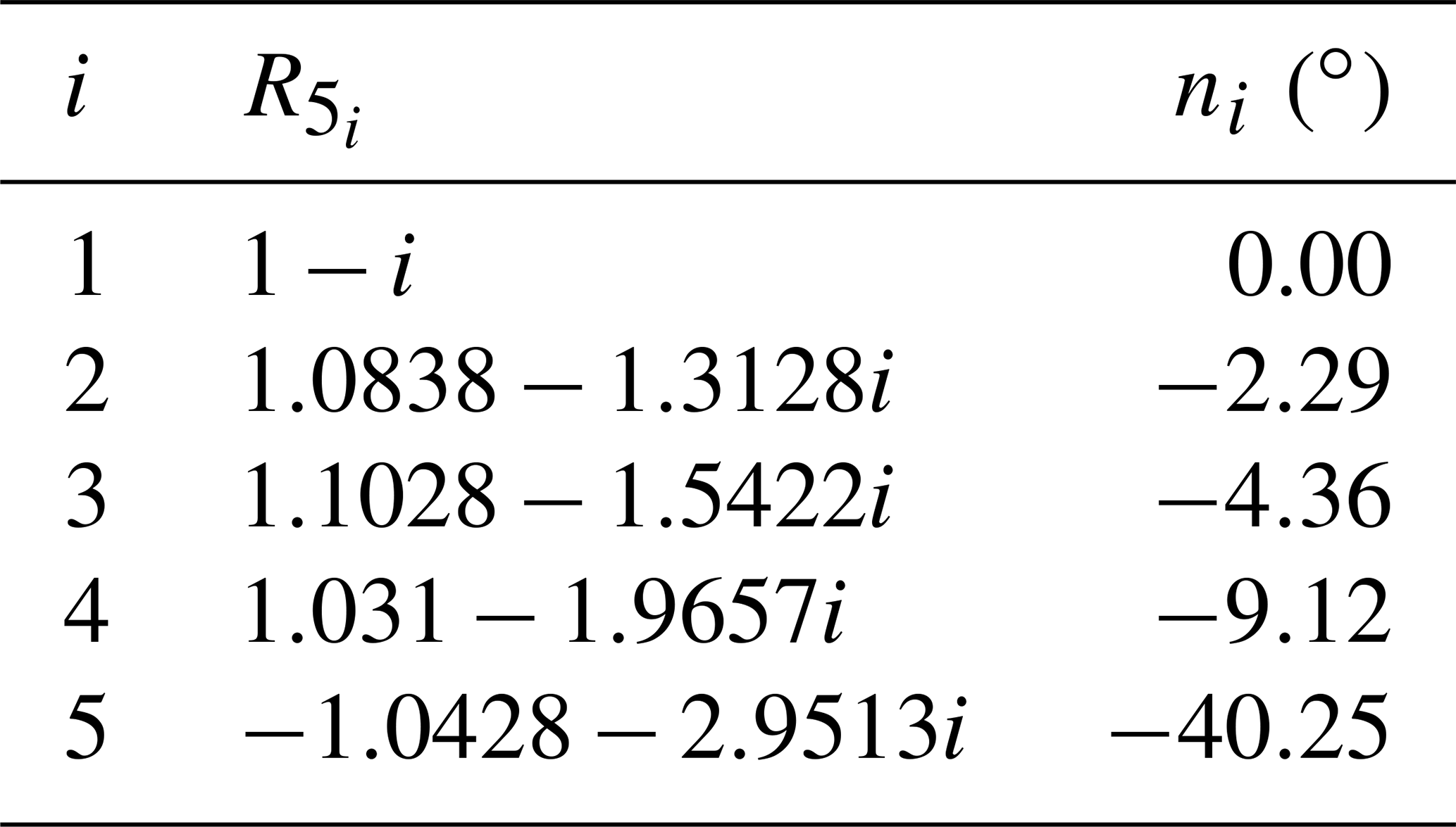
Table 2The real part (Re.) and the imaginary part (Im.) of the selected result.
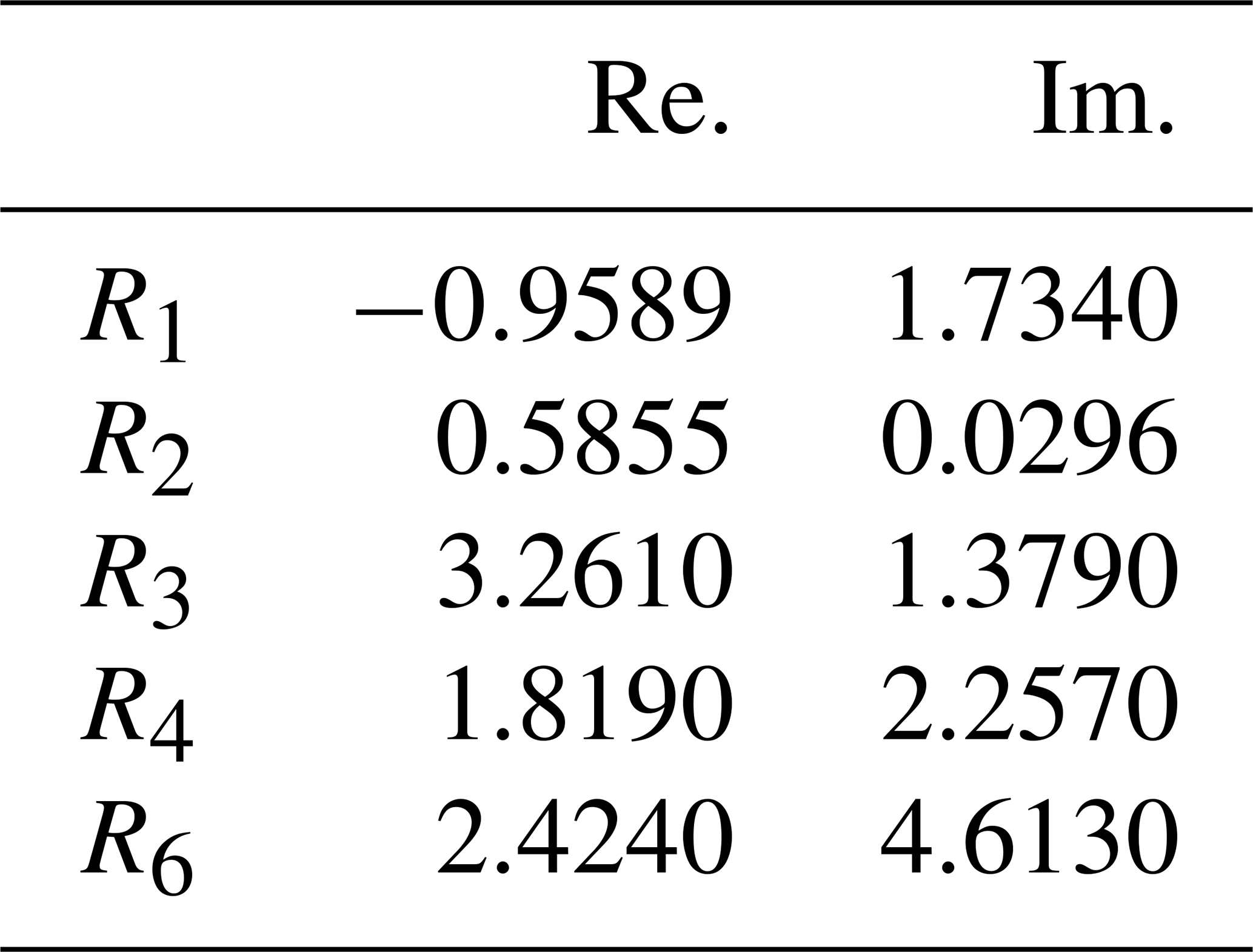
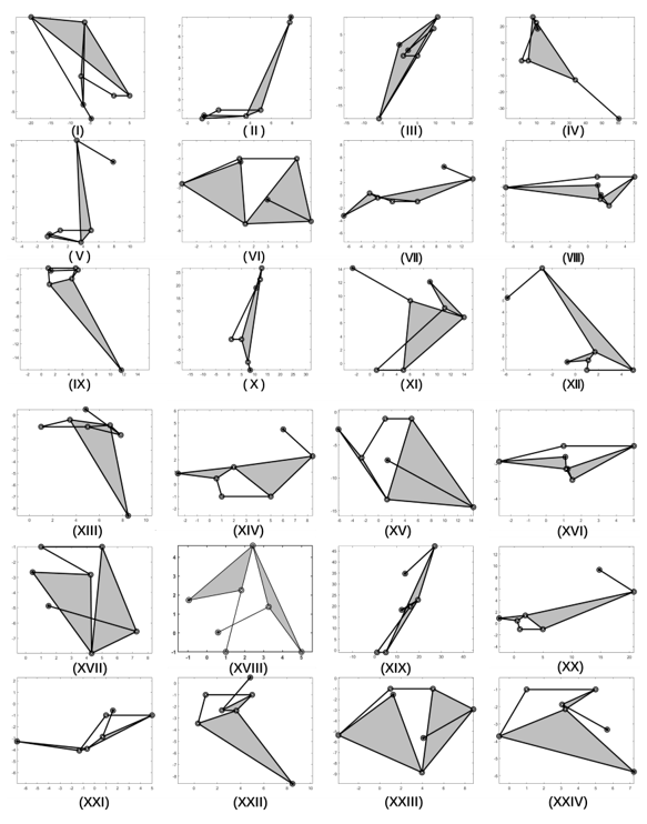
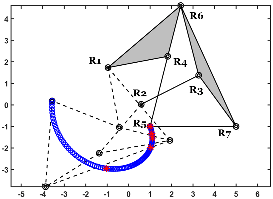
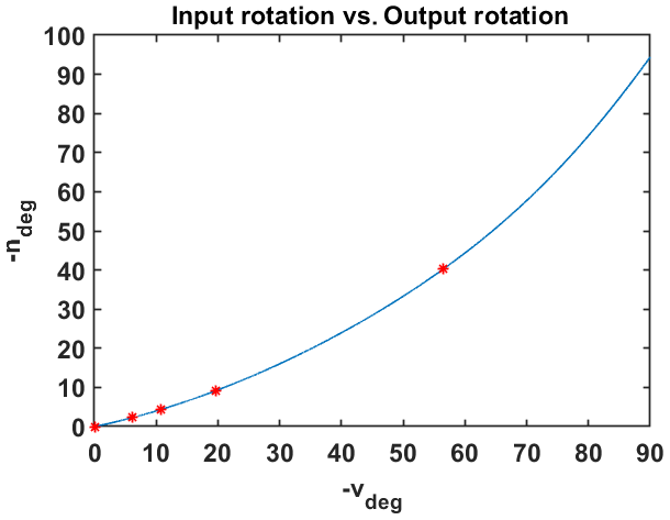
Although the selected results meet the design requirements, some of them are not practically suitable for the mechanism. The dead center position is not within the range of the motion of the optimized mechanism with the input rotation v. The size of the whole mechanism is required to be compact. The position of the foot is designed in the lowest position to make the fabrication convenient. The link R5R7 shown in Fig. 5, i.e., (II–X), is not in the lowest position, which means that the linkage cannot be used directly for the fabrication of the robot. Other configurations such as XIV, XIX, and XX are not compact, as other links have larger sizes compared to the size of R5R7. The selected result is in Table 2, which is the configuration shown in XVIII. Figure 6 shows the output motion of the selected six-bar linkage configuration. The dashed lines represent the configuration when . The blue dots are the positions of , and the red marks denote the target positions, which are shown in Table 1. Figure 7 shows the relationship between the input rotation v and the output angle n in the degree where the red marks denote the objective rotation.
5.1 The swimming function of the propulsive mechanism
The propulsion produced in frog's swimming is mostly caused by drag force, while the lift-based propulsion does not contribute dominantly (Gal and Blake, 1988). The hypothesis is supported by Christoffer's research (Johansson and Lauder, 2004). From the blade element model, the thrust which propels the frog in water and the drag which impedes the swimming can be estimated. The basic blade element model for estimating generated force is written as follows:
In Eq. (25), ρ and Cd are the fluid density and the drag coefficient, respectively. Ap is the projected area in the direction of the movement, and in this study, it can be controlled by changing β in the designed mechanism, as shown in Fig. 8. V is the velocity relative to the velocity of the fluid flows. Hence, the generated force in the shadow area in the power stroke phase shown in Fig. 8 is as follows:
Moreover, in the following:
vy is the speed of the shadow area in the direction of R1y, and φ is the angle between R10R9 and R1y in Eq. (26). Similarly, the force generated in the shadow area in the recovery phase is as follows:
Hence, in the following:
The thrust is generated in the power stroke phase of a frog, while the drag is produced when the foot recovers to the initial state. The designed mechanism has the capability to mimic the swimming locomotion of a frog. The stroke of the swimming is divided into the power stroke phase, the gliding phase, and the recovery phase, either in the asynchronous or the synchronous locomotion. To mimic the locomotion of the hindlimbs, the angle β keeps to −90∘ to maximize the projected area in R1y direction, which is similar to the expanded webbed foot of a frog, as demonstrated in Fig. 9a. The rotation μ actuated in the pivot joint R1 drives the foot backward in the power stroke phase, while β stays unchanged (shown in Fig. 9b). β changes to −5∘ to decrease the projected area and avoid interference among the linkages at the beginning of the recovery phase, as shown in Fig. 9d. μ rotates back to the initial state, and the projected area remains unchanged in the recovery phase, which is demonstrated in Fig. 9c. Moreover, the thrust or drag generated in one cycle of the swimming locomotion can be adjusted by changing the angular velocity of μ or the projected area controlled by β.
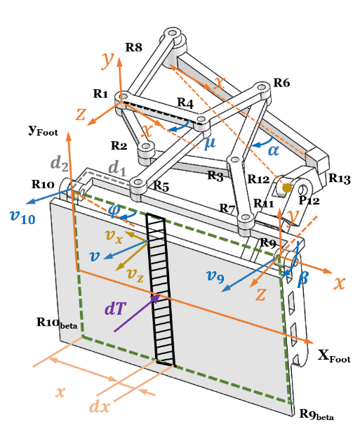
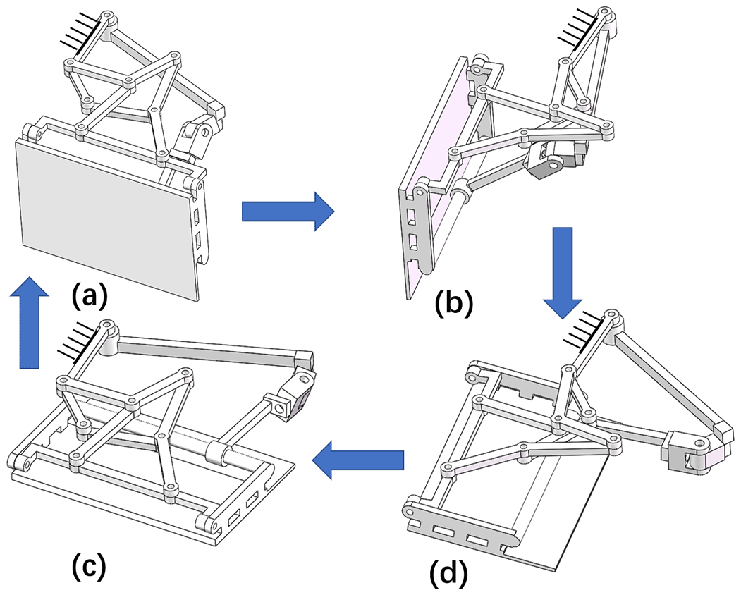
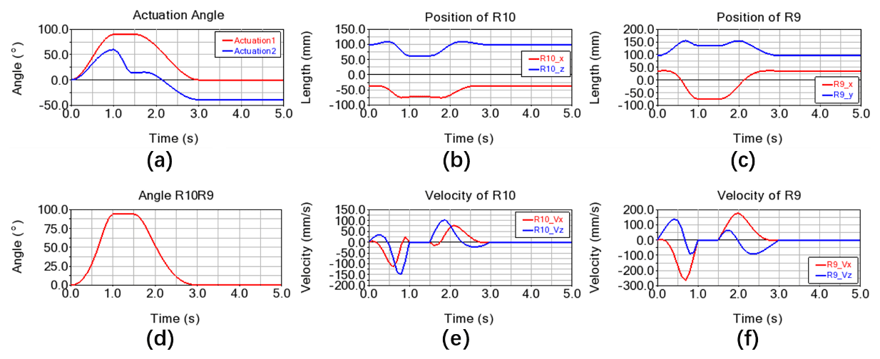
Figure 10(a) The rotation actuated on the R1 and R8 related to the swimming cycle mimicking a frog's swimming locomotion. (b) The position components in the x and y directions of R10. (c) The position components in the x and y directions of R9. (d) The rotation of link R10R9. (e) The velocity components in the x and y directions of R10. (f) The velocity components in the x and y directions of R9.

Figure 10 shows the kinematic results of one swimming cycle, which is demonstrated in Fig. 9. The step input is shown in Fig. 10a, where Actuation 1 is the rotation of joint R1, inducing the rotation of link R10R9, and Actuation 2 is the rotation of R8, which controls the angle β. Actuation 1 and Actuation 2 can be acquired from the inverse kinematic model of the mechanism. The power stroke phase starts from t=0 to t=1 s, as a demonstration. The glide phase is from t=1 to t=1.5 s, where the foot keeps static. In the recovery phase, from t=1.5 to t=3 s, the foot retracts with a small projected area, as β keeps in 5∘. Figure 11 shows the estimated result of Eq. (29) of one swimming cycle, where the maximum thrust is generated in the power stroke phase. The drag produced in the recovery phase decreases dramatically as the rotation of the foot is lower, and the projected area is drastically small compared to that in the power stroke phase.
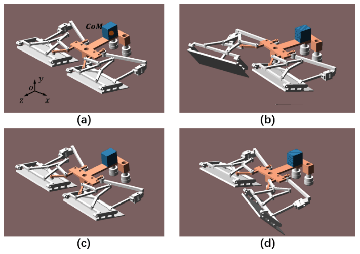
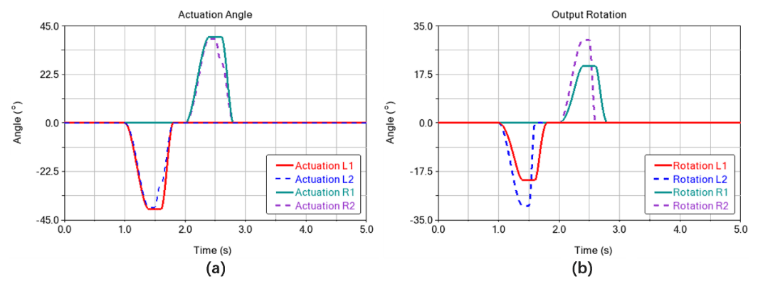
Figure 13(a) The actuation in one sprawling cycle. (b) The output rotation of a pair of mechanisms in one sprawling cycle.
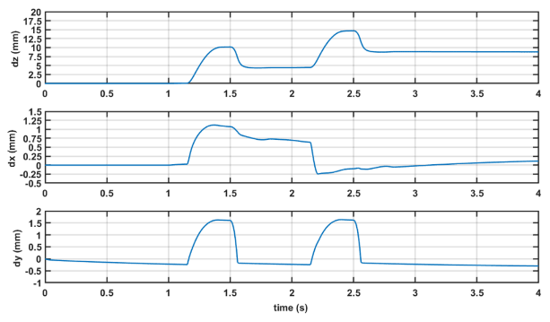
Figure 14The components of displacement of the center of mass (CoM) in the x, y, and z directions in one sprawling cycle.
5.2 The sprawling motion of the propulsive mechanism
Differing from the aquatic locomotion, where hindlimbs are mostly used, the terrestrial locomotion of frogs is generated by both the forelimbs and the hindlimbs. The terrestrial walking frogs use a quadrupedal sprawling, and the footfall pattern is formed by the diagonal limbs contacting the ground. During the subsequent strides of the sprawling, the position of the trunk shifts from side to side due to the mediolateral reaction force. The lateral forces produced by the hindlimb shift the body over the contralateral forelimb during the period when the diagonal pair is in contact with the ground. The locomotion of the foot utilized in the sprawling is a complex spatial motion, such as vertical retraction, and adjustments in forelimb protraction exist. The sprawled postures allow walking frogs to locomote with minimal pitch adjustments, and the lateral forces produced by limbs during a sprawled gait have been shown to increase stability in the horizontal plane and reduce pitching and rolling moments about the center of mass (Reynaga et al., 2018).
We concentrate on the terrestrial propulsion actuated by the hindlimbs which are different to those of the real frogs. To overcome the disadvantage of lacking the forelimbs with multiple DoF, we use three omnidirectional wheels. Of these, two omnidirectional wheels working as the shoulders are set symmetrically in front of the robotic trunk, and the other one is assembled at the end to support the trunk on the ground. The robot shown in Fig. 12 utilizes the subsequent locomotion of each pair of the designed hybrid linkage mechanism, and the center of mass (CoM) of the trunk is estimated to be in the front of the trunk. The proposed model is validated in Adams software. In Fig. 12b, the left foot contacts the ground, and the trunk shown in orange is propelled from t=1 to t=1.4 s, with link R10R9 that translates mostly with a slight rotation as −24∘, and β becomes −30∘. In Figs. 12b to c, the left hindlimb recovers to the initial state. The link R10R9 recovers from t=1.4 to t=1.6 s while the rotation of the foot, about R10R9, recovers to the initial state from t=1.5 to t=1.6 s. The actuation of the right hindlimb is symmetric, from t=2 toct=2.6 s, as shown in Fig. 13a, where Rotation L1 and Rotation L2 represent the rotation of the link R10R9 and the rotation of the foot about R10R9 of the left hindlimb, respectively. Rotation R1 and Rotation R2 in Fig. 13b represent the rotation of the link R10R9 and the rotation of the foot about R10R9 of the right hindlimb, respectively.
The translational output of the CoM of the robotic trunk is presented in Fig. 14, from which we can see that the direction of the forward motion is −z. The displacement generated with the Actuation 1 and Actuation 2 input on the designed mechanism on one side simultaneously is 10 mm, and the trunk moves back with a displacement of 5.6 mm. The total displacement in the forward direction is 8.8 mm after a pair of hindlimbs were actuated. The displacement in the x direction reveals the turning ability of the designed mechanism. The displacement in the z direction is not 0 after one sprawling cycle is caused by the accumulated error in the numerical computation.
In this paper, we propose a novel united propulsive mechanism inspired by a frog's hindlimb, which consists of a planar six-bar linkage mechanism and a spatial four-bar linkage mechanism. The two different types of mechanisms connect in the foot, which forms a spatial closed-loop. The foot has 2 DoF, which are fully actuated from the input in the two sub-chains. With the spatial closed-loop linkage, the number of actuators for the amphibious function decreased dramatically to 2 compared to the mechanism employing a serially actuated strategy. The configuration of the planar six-bar linkage is numerically solved as a body guidance problem from the synthesis equations, based on the homotopy continuation. The forward kinematic analysis from the geometrical features is directly established, which overcomes the multiplicity of the mechanical configurations. The inverse kinematic analysis is conducted as well to find the actuations with specified output motion. The preliminary simulations validate the amphibious function of the designed mechanism. In the scenario of the aquatic locomotion, the thrust generated can be maximized by tuning the rotational speed and the projected area of the foot, which is similar to the strategy of swimming frogs. In the other scenario, the sprawling model is simplified, which is propelled only by the hindlimbs. The simulated results show the capability of moving forward and turning with respect to a specially designed gait. The result of the stride is not as effective as that of the sprawling frogs, which is due to the lack of the forelimbs, although the hindlimb proves the feasibility for terrestrial function. We will conduct the experiments with the implementation of motor control and optimize the mechanism with other planar mechanisms, such as an eight-bar linkage, for a better performance of both the aquatic and terrestrial functions.
Code and data can be made available upon request.
YT provided the idea and wrote the first draft of the paper. XY conducted the mobility analysis of the mechanism. XZ and SZ finished the forward kinematic and inversed kinematic modeling. WZ calculated the parameters of the planar six-bar linkage. YS verified the function of the mechanism in the simulation. YW was responsible for planning and coordinating the steps of the research.
The contact author has declared that neither they nor their co-authors have any competing interests.
Publisher's note: Copernicus Publications remains neutral with regard to jurisdictional claims in published maps and institutional affiliations.
This work has been supported by National Key Research and Development Program of China (grant no. 2021YFB2012104), National Natural Science Foundation of China (grant no. 52105023), the Natural Science Foundation of Jiangsu Province (grant no. BK20210341), and the Fundamental Research Funds for the Central Universities (grant no. 309201A8801).
This paper was edited by Daniel Condurache and reviewed by two anonymous referees.
Bates, D. J., Hauenstein, J. D., Sommese, A. J., and Wampler, C. W.: Bertini: Software for Numerical Algebraic Geometry, Bertini Home Page [code], https://doi.org/10.7274/R0H41PB5, 2013.
Collings, A. J., Porro, L. B., Hill, C., and Richards, C. T.: The impact of pelvic lateral rotation on hindlimb kinematics and stride length in the red-legged running frog, R. Soc. Open Sci., 6, 190060, https://doi.org/10.1098/rsos.190060, 2019.
Crespi, A., Karakasiliotis, K., Guignard, A., and Ijspeert, A. J.: Salamandra Robotica II: An amphibious robot to study salamander-like swimming and walking gaits, IEEE T. Robot., 29, 308–320, https://doi.org/10.1109/TRO.2012.2234311, 2013.
Dey, B. B., Manjanna, S., and Dudek, G.: Ninja legs: Amphibious one degree of freedom robotic legs, in: 2013 IEEE/RSJ International Conference on Intelligent Robots and Systems, 2013 IEEE/RSJ International Conference on Intelligent Robots and Systems (IROS), Tokyo, Japan, 5622–5628, https://doi.org/10.1109/IROS.2013.6697171, 2013.
Fan, J., Wang, S., Yu, Q., and Zhu, Y.: Swimming Performance of the Frog-Inspired Soft Robot, Soft Robotics, 7, 615–626, https://doi.org/10.1089/soro.2019.0094, 2020.
Floyd, S. and Sitti, M.: Design and Development of the Lifting and Propulsion Mechanism for a Biologically Inspired Water Runner Robot, IEEE T. Robot., 24, 698–709, https://doi.org/10.1109/TRO.2008.924258, 2008.
Floyd, S., Keegan, T., Palmisano, J., and Sitti, M.: A Novel Water Running Robot Inspired by Basilisk Lizards, in: 2006 IEEE/RSJ International Conference on Intelligent Robots and Systems (IROS), Beijing, China, 5430–5436, https://doi.org/10.1109/IROS.2006.282111, 2006.
Gal, J. M. and Blake, R. W.: Biomechanics of frog swimming I. estimation of the propulsive force generated by Hymenochirus Boettgeri, J. Exp. Biol., 138, 399–411 1988.
Guo, S., He, Y., Shi, L., Pan, S., Xiao, R., Tang, K., and Guo, P.: Modeling and experimental evaluation of an improved amphibious robot with compact structure, Robot. Comput.-Integr. Manuf., 51, 37–52, https://doi.org/10.1016/j.rcim.2017.11.009, 2018.
Huang, C.-Y., Kuo, C.-N., Pan, L.-H., Lin, S.-Y., and Chou, J. J.: Claw-Wheel: A transformable robot for search and investigation in amphibious environment, in: 2017 IEEE/RSJ International Conference on Intelligent Robots and Systems (IROS), Vancouver, BC, 6541–6546, https://doi.org/10.1109/IROS.2017.8206564, 2017.
Ijspeert, A. J., Crespi, A., Ryczko, D., and Cabelguen, J.-M.: From Swimming to Walking with a Salamander Robot Driven by a Spinal Cord Model, Science, 315, 1416–1420, https://doi.org/10.1126/science.1138353, 2007.
Johansson, L. C. and Lauder, G. V.: Hydrodynamics of surface swimming in leopard frogs (Rana pipiens), J. Exp. Biol., 207, 3945–3958, https://doi.org/10.1242/jeb.01258, 2004.
Karakasiliotis, K., Thandiackal, R., Melo, K., Horvat, T., Mahabadi, N. K., Tsitkov, S., Cabelguen, J. M., and Ijspeert, A. J.: From cineradiography to biorobots: An approach for designing robots to emulate and study animal locomotion, J. R. Soc. Interface., 13, 20151089, https://doi.org/10.1098/rsif.2015.1089, 2016.
Kashem, S. B. A., Jawed, S., Ahmed, J., and Qidwai, U.: Design and Implementation of a Quadruped Amphibious Robot Using Duck Feet, Robotics, 8, 77, https://doi.org/10.3390/robotics8030077, 2019.
Kim, H., Lee, D., Jeong, K., and Seo, T.: Water and Ground-Running Robotic Platform by Repeated Motion of Six Spherical Footpads, IEEE/ASME Trans. Mechatron., 21, 175–183, https://doi.org/10.1109/TMECH.2015.2435017, 2016.
Kim, H., Sitti, M., and Seo, T.: Tail-Assisted Mobility and Stability Enhancement in Yaw and Pitch Motions of a Water-Running Robot, IEEE/ASME Trans. Mechatron., 22, 1207–1217, https://doi.org/10.1109/TMECH.2017.2679188, 2017.
Kim, T., Song, Y., Song, S., and Yu, S. C.: Underwater Walking Mechanism of Underwater Amphibious Robot Using Hinged Multi-modal Paddle, Int. J. Control Autom., 19, 1–12, https://doi.org/10.1007/s12555-020-0371-3, 2020.
Liang, X., Xu, M., Xu, L., Liu, P., Ren, X., Kong, Z., Yang, J., and Zhang, S.: The AmphiHex: a Novel Amphibious Robot with Transformable Leg-flipper Composite Propulsion Mechanism, in: 2012 IEEE/RSJ International Conference on Intelligent Robots and Systems (IROS), Vilamoura-Algarve, Portugal, 3667–3672, 2012.
Nyakatura, J. A., Melo, K., Horvat, T., Karakasiliotis, K., Allen, V. R., Andikfar, A., Andrada, E., Arnold, P., Lauströer, J., Hutchinson, J. R., Fischer, M. S., and Ijspeert, A. J.: Reverse-engineering the locomotion of a stem amniote, Nature, 565, 351–355, https://doi.org/10.1038/s41586-018-0851-2, 2019.
Pandey, J., Reddy, N. S., Ray, R., and Shome, S. N.: Biological swimming mechanism analysis and design of robotic frog, in: 2013 IEEE International Conference on Mechatronics and Automation, 2013 IEEE International Conference on Mechatronics and Automation (ICMA), Takamatsu, Kagawa, Japan, 1726–1731, https://doi.org/10.1109/ICMA.2013.6618176, 2013.
Park, H. S. and Sitti, M.: Compliant footpad design analysis for a bio-inspired quadruped amphibious robot, in: 2009 IEEE/RSJ International Conference on Intelligent Robots and Systems, 2009 IEEE/RSJ International Conference on Intelligent Robots and Systems (IROS), St. Louis, MO, USA, 645–651, https://doi.org/10.1109/IROS.2009.5354680, 2009.
Plecnik, M., McCarthy, J. M., and Wampler, C. W.: Kinematic Synthesis of a Watt I Six-Bar Linkage for Body Guidance, in: Advances in Robot Kinematics, edited by: Lenarčič, J. and Khatib, O., Springer International Publishing, Cham, 317–325, https://doi.org/10.1007/978-3-319-06698-1_33, 2014.
Plecnik, M. M. and McCarthy, J. M.: Design of Stephenson linkages that guide a point along a specified trajectory, Mech. Mach. Theory, 96, 38–51, https://doi.org/10.1016/j.mechmachtheory.2015.08.015, 2016a.
Plecnik, M. M. and McCarthy, J. M.: Kinematic synthesis of Stephenson III six-bar function generators, Mech. Mach. Theory, 97, 112–126, https://doi.org/10.1016/j.mechmachtheory.2015.10.004, 2016b.
Plecnik, M. M. and McCarthy, J. M.: Computational Design of Stephenson II Six-Bar Function Generators for 11 Accuracy Points, J. Mech. Robot., 8, 011017, https://doi.org/10.1115/1.4031124, 2016c.
Reynaga, C. M., Astley, H. C., and Azizi, E.: Morphological and kinematic specializations of walking frogs, J. Exp. Zool., 329, 87–98, https://doi.org/10.1002/jez.2182, 2018.
Sommese, A. J. and Wampler, C. W.: The numerical solution of systems of polynomials arising in engineering and science, World Scientific, Hackensack, NJ, 401 pp., https://doi.org/10.1142/5763, 2005.
Tang, Y., Qin, L., Li, X., Chew, C.-M., and Zhu, J.: A frog-inspired swimming robot based on dielectric elastomer actuators, in: 2017 IEEE/RSJ International Conference on Intelligent Robots and Systems (IROS), 2017 IEEE/RSJ International Conference on Intelligent Robots and Systems (IROS), Vancouver, BC, 2403–2408, https://doi.org/10.1109/IROS.2017.8206054, 2017.
Xing, H., Guo, S., Shi, L., Hou, X., Liu, Y., Liu, H., Hu, Y., Xia, D., and Li, Z.: A Novel Small-scale Turtle-inspired Amphibious Spherical Robot, in: 2019 IEEE/RSJ International Conference on Intelligent Robots and Systems (IROS), 2019 IEEE/RSJ International Conference on Intelligent Robots and Systems (IROS), Macau, China, 1702–1707, https://doi.org/10.1109/IROS40897.2019.8968304, 2019.
Zhang, S., Zhou, Y., Xu, M., Liang, X., Liu, J., and Yang, J.: AmphiHex-I: Locomotory Performance in Amphibious Environments with Specially Designed Transformable Flipper Legs, IEEE/ASME Trans. Mechatron., 21, 1720–1731, https://doi.org/10.1109/TMECH.2015.2490074, 2016.
- Abstract
- Introduction
- Mechanical design
- Kinematic analysis of the spatial linkage mechanism
- Design of the six-bar linkage based on homotopy continuation
- The amphibious application of the designed propulsive mechanism
- Conclusion
- Code and data availability
- Author contributions
- Competing interests
- Disclaimer
- Financial support
- Review statement
- References