the Creative Commons Attribution 4.0 License.
the Creative Commons Attribution 4.0 License.
 | 29 Apr 2022
Structural design of multi-body heave wave energy conversion system and analysis of energy efficiency of floating body on water surface
Dongsheng Cong
Hao Jing
Ruijun Zhang
Zhongyue Lu
Jianzhong Shang
Zirong Luo
Due to the defects of the internal structure and energy supply carrier, conventional deep sea unoccupied marine equipment cannot meet the requirements of low power consumption. In this paper, the whole structure of a multi-body heave wave energy conversion system was designed to capture and convert wave energy. The conversion system consists of a floating body, an underwater absorber and a power takeoff system (PTO). The dynamic model of the energy conversion system and the mathematical model of energy efficiency evaluation were established according to the dynamic analysis. Based on the real service environment in the South China Sea, the energy efficiency characteristics of floating bodies with different shapes were simulated, and the amplitude response operator (RAO), radiation damping, added mass and Froude–Krylov force of floating bodies with different shapes were compared. Then, the optimal energy efficiency parameters of surface floating body were explored. Finally, the correctness of the conclusion was verified by the energy efficiency test. The results show that, under the limitation of low power consumption and space scale, the energy conversion system of an axisymmetric rotary body with the same sea conditions, same material and the largest scale can significantly improve the conversion efficiency, and the spherical rotary body performs the best, which makes the unoccupied marine equipment have a broad prospect for development.
- Article
(5771 KB) - Full-text XML
- BibTeX
- EndNote


Low-power unoccupied ocean devices, such as unoccupied surface water vehicles, ocean robots and ocean buoys are widely used in unoccupied combat, deep sea exploration, marine communications and so on (Bertaska and Ellenrieder, 2018; Mousazadeh et al., 2018; Zoss et al., 2018; Banazadeh et al., 2017; Venkatesan et al., 2018). For the unoccupied marine equipment in the deep sea, a continuous, stable, efficient and reliable energy supply will provide a fundamental guarantee for the long-term operation of low-power unoccupied marine equipment (Cong et al., 2018; Sun et al., 2018). At present, battery use is one of the common energy supply carriers for unoccupied marine equipment. However, due to its low energy density, short service life and frequent maintenance, the battery use needs to increase the carrying capacity to meet the working requirements of a long range and long endurance. The internal space of unoccupied marine equipment limits the carrying capacity of batteries (Mendez et al., 2014). The development of new and sustainable sources of energy supply is an inevitable trend.
At the forefront of the energy transition and research efforts is renewable energy research, such as wind (Cruz and Atcheson, 2016; Kaldellis and Apostolou, 2017; Kumar et al., 2016; Serrano-González and Lacal-Arántegui, 2016), solar energy (Kannan and Vakeesan, 2016; Sampaio and González, 2017; Kabir et al., 2018) and hydropower (Zarfl et al., 2015; Bildirici and Gökmenoğlu, 2017). Because unoccupied marine equipment works in the marine environment for a long time, under the condition of effective and direct use of environmental resources, marine renewable energy can become an ideal energy supply resource for low-power unoccupied marine equipment. Compared with other types of ocean energy, such as the tidal current/tidal range, ocean current and salinity gradient, wave energy has the advantages of abundant reserves, high energy density, wide propagation range and no regional restrictions (Cruz et al., 2008). For the conversion of marine energy (especially wave energy), scholars worldwide have done a lot of work. Clemente et al. (2021) presented a review of synergetic technologies with the potential for hybridization and/or co-location with wave energy converters. Potential applications of wave energy conversion devices, within the context of nearshore and offshore markets that minimize/eliminate, respectively, mainland grid connection and inherent costs are also discussed. Cuadra et al. (2016) summarized the application of wave energy in the resource estimation, design and control of wave energy converter, and proposed that fuzzy calculation could be used to estimate wave parameters and control floating wave energy converter. Fadaeenejad et al. (2014) discussed the wave energy potential for remote islands in this review by regarding environment impacts, various types of wave energy converters and applied wave power projects for various islands. Seyedeh et al. (2018) studied a wave energy collection system based on piezoelectric beam column and studied the application of a self-tuning buoy based on wave frequency. Chiba et al. (2013) tested the simple proportional model of the electroactive polymer artificial muscle (EPAM)-based wave energy harvesting system, and the energy output was found to be largely independent of the wave period.
At present, scholars worldwide have carried out some exploration in the research of unoccupied marine equipment energy supply technology. In 1980s, a Swedish interproject service (IPS) company developed a multi-body heave wave energy conversion device IPS buoy (Noren, 1981). At the end of the 20th century, Weber et al. (2009) developed a multi-body heave wave energy conversion device (Weber et al., 2009). In 2005, the École Polytechnique Research Center developed a single rolling (pitching) wave energy conversion device (Babarit et al., 2005). In addition, Wang (2013) analyzed the inertial wave energy conversion devices of a single degree of freedom and 2 degrees of freedom inertial pendulums and, combined with the motion of floating body, explored the influence law of pendulum length and natural angular frequency on the stability of the whole machine. The working principle of the abovementioned traditional unoccupied marine equipment energy conversion system is composed of a three-level conversion mode, that is, the surface floating body drives the underwater buoy to heave, the buoy drives the impeller to rotate and the impeller stores the energy in the accumulator through the gear. However, due to the three-stage conversion mode of the energy conversion system of the traditional unoccupied marine equipment, the periodic oscillation of the wave could not be directly converted into the high-speed continuous motion of the power takeoff system (PTO), which seriously affects the efficiency of the wave energy conversion. Some scholars have improved and studied it. Zhang et al. (2012) put forward some basic improvement measures for the PTO system by using the hydraulic system and evaluated and proposed each measure. Although these studies have made some progress, there was a lack of structural design to fundamentally solve such problems. At the same time, because of the intermittent resources, market liberalization and energy storage restrictions (Moriarty and Honnery, 2016; Trainer, 2017; Blazquez et al., 2018) of renewable energy, under the existing conditions, increasing the utilization rate of renewable energy has gradually been given more attention by scholars at home and abroad.
In conclusion, the structural problems of traditional energy conversion system and the improvement of wave energy conversion efficiency need to be solved urgently. At present, the research of wave energy conversion mainly focuses on the large-scale grid-connected power generation and large-scale wave energy power of unoccupied marine equipment. However, there is a lack of research on a small-scale, small power generation, portable, micro-wave energy conversion system for low-power unoccupied marine equipment. Therefore, the whole structure of the multi-body heave wave energy conversion system is designed for wave energy capture and secondary conversion. The dynamic model and energy efficiency evaluation mathematical model of energy conversion system of surface floating body was established according to the dynamic analysis. Based on the real service environment in the South China Sea, the energy efficiency characteristics of floating bodies with different shapes were analyzed by numerical simulation, and the optimal energy efficiency parameters of surface floating body were explored. Finally, the correctness and feasibility of the conclusion were verified by the energy efficiency characteristic test.
The remainder of the rest of this paper is organized as follows. In Sect. 2, the whole structure of multi-body heave wave energy conversion system is designed for the capture and conversion of wave energy. The dynamic model of the energy conversion system and the mathematical model of energy efficiency evaluation of floating body were established according to the dynamic analysis. In Sect. 3, based on the real service environment in the South China Sea, the energy efficiency characteristics of floating bodies with different shapes were simulated, and the amplitude response operator (RAO), radiation damping, added mass and Froude–Krylov force of floating bodies with different shapes were compared. The optimal energy efficiency parameters of surface floating body were explored. In Sect. 4, the correctness of the conclusion was verified by the energy efficiency test. Finally, the conclusion is drawn in Sect. 5.
2.1 Structural design
To solve the problems caused by three-stage conversion mode in traditional energy conversion system and improve its conversion efficiency, a multi-body heave wave energy conversion system was designed. The multi-body heave wave energy conversion system was mainly composed of surface floating body, underwater absorber and power takeoff system (PTO). Its basic structure and working principle are shown in Fig. 1. The floating body on the sea surface absorbs the wave energy and generates the heave motion. The underwater absorber transforms the up-heave motion into continuous unidirectional rotation motion, and the PTO system converts the mechanical energy into electrical energy. When the floating body on the water surface rises with the wave, then the wire rope drags the PTO system of the underwater absorber, the forward and reverse impellers, and the stable blades to rise together. The upper surface of the energy-absorbing blade is subject to the downward action of water resistance, and the energy-absorbing blade oscillates adaptively downward to generate a forward thrust in the reverse direction. Driven by the thrust of the blade, the forward-rotating impeller rotates counterclockwise and the reverse rotating impeller rotates clockwise. When the floating body on the water surface sinks with the wave, the lower surface of the energy-absorbing blade is subject to the upward action of water resistance, and the energy-absorbing blade swings up adaptively, generating a forward thrust in the reverse direction. Driven by the thrust of the energy absorbing blade, the forward-rotating impeller rotates counterclockwise and the reverse-rotating impeller rotates clockwise. According to the different impact direction of water flow, the blade deflection direction is adjusted adaptively. The upper and lower impellers act as the components directly interacting with the water flow and provide a continuous rotating motion for the generator during the rising and sinking process of the underwater absorber. In addition, the maximum deflection angle of impeller blade can be adjusted actively according to different sea conditions to improve the maximum power generation efficiency.
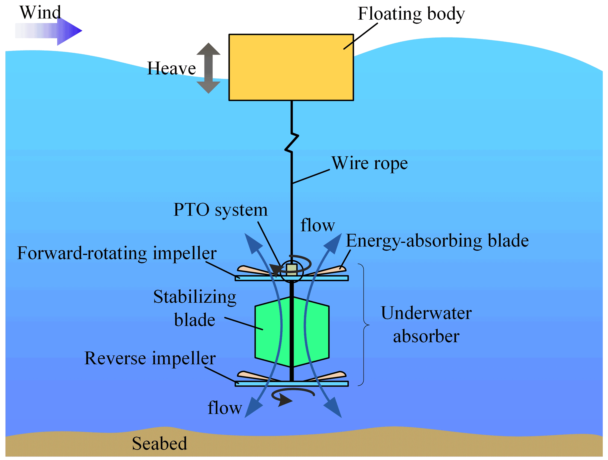
Figure 1Schematic diagram of the working principle of a multibody heave wave energy converter.
Due to the irregularity of the waves, the instantaneous attitude of the floating body on the water surface is uncertain. According to the engineering practice experience, on the basis of the multi-body heave wave energy conversion system, two types of water surface floating bodies, i.e., axisymmetric revolving body (cylinder, cone, sphere, etc.) and axisymmetric non-revolving body (cube, pyramid, prism, etc.), were designed. The different shapes of the surface floating bodies are connected with an impeller-type underwater absorber to ensure that there is no influence of other parameters.
2.2 Dynamic model based on Froude–Krylov method
When a floating body on the water surface moves up and down, its structural characteristic size is much smaller than the wavelength. According to the linear wave theory, the wave force on the floating body on the water surface is usually solved by the Froude–Krylov method (Giorgi and Ringwood, 2017). To better establish the dynamic model and explore the dynamic characteristics, this paper simplifies the multi-body heave wave energy conversion system in the real service environment.
-
The floating body of the multi-body heave wave energy converter floats freely on the liquid surface. Under the action of linear regular waves, the floating body on the water surface heaves slightly.
-
The surface floating body, cable and underwater absorber are unified as a whole. The unified whole of the three is simplified as a cylindrical double floating body device, and its motion system is simplified as a 2 degrees of freedom spring damping system.
-
The motion of the double floating body is a rigid body motion, and the deformation of the double floating body structure and the motion constraints of the whole system are ignored.
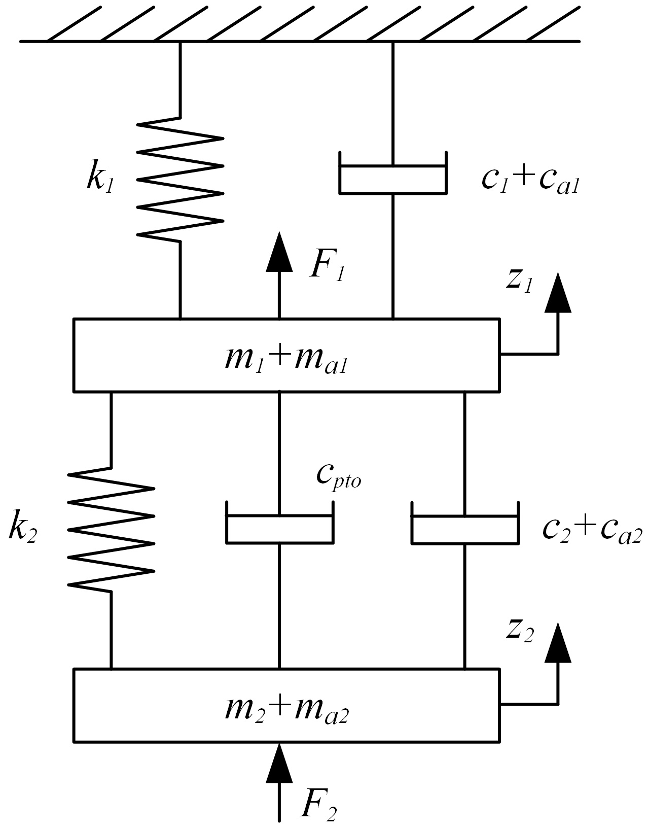
The dynamic model of the simplified energy conversion system in ascending motion is shown in Fig. 2. The free heave motion equation of double floating body structure is as follows:
where z1 and z2 are the displacement responses of the upper and lower floating structures in the heave direction, starting from the static equilibrium position, and are the velocity responses of the upper and lower floating structures in the heave direction, and and are the corresponding acceleration responses. m1 and m2 are the masses of the upper and lower floating bodies. c1 and c2 are the linear damping coefficients of the upper and lower floating bodies, and cpto is the linear damping coefficient of the PTO system. k1 and k2 are the linear stiffness coefficients of the upper and lower floating bodies. F1 and F2 are the total forces on the upper and lower floating bodies, respectively. ma1 and ca1 are the added mass and damping of the upper floating body. ma2, ca2 are the added mass and damping of the lower floating body.
Then Eq. (1) is arranged as a matrix, as follows:
where M, C and K are mass matrix, linear damping matrix and linear stiffness matrix, respectively. Ma, Ca and Cpto are the added mass matrix, radiation damping matrix and linear damping matrix of PTO system, respectively. Fe, Fhys and G are wave-exciting force matrix, hydrostatic restoring force matrix and gravity matrix, respectively. Z is the displacement vector of the 2 degrees of freedom motion of the upper and lower floating bodies.
The Froude–Krylov method is used to estimate the wave force on a floating body.
where c is the diffraction correction coefficient, FFKdy is the dynamic Froude–Krylov force, and FD is the diffraction force.
According to linear wave theory, the dynamic Froude–Krylov force dynamic is negligible. The Froude–Krylov force is as follows:
where S is the wet surface area of the floating body, n is the normal of the wet surface of the floating body, and Pdy is the dynamic pressure. According to the linear wave theory, the water quality point dynamic pressure at any point on the surface floating body can be expressed as 33 in the following:
where H is the wave height, x is the direction of wave propagation in the global coordinate system, is the horizontal displacement of the floating body in the local coordinate system, d is the water depth, z is the movement displacement of the floating body in the vertical direction in the global coordinate system, ω is the wave circle frequency, k is the wave number, , ρ is the density, and g is the acceleration of gravity.
2.3 Mathematical model of energy efficiency evaluation of the floating body on a water surface
In the working process of the multi-body heave wave energy conversion system, the performance of the conversion system mainly focuses on the collection and conversion of wave energy. The collection of wave energy is mainly completed by the floating body on the water surface, and its conversion efficiency directly affects the conversion efficiency of the whole system. The energy efficiency conversion ratio of a floating body is defined as the ratio of the total energy of converted waves to the total energy of incident waves. The definition is as follows:
where η is the energy efficiency conversion ratio of a surface floating body, Eabs is the total energy of waves captured by a floating body system when it resonates with a linear wave, Eall is the total energy of the incident wave in the unit wavelength range, m and ma are the mass and additional mass of the floating body on the water surface, respectively, ρ is the density of the sea water, λ is the wave length, Awp is the cross-sectional area of the floating body, and ω is the wave circle frequency. In addition, the motion response characteristics of a floating body under linear wave action are usually characterized by the amplitude response operator (RAO), which is defined as the ratio of the corresponding degree of freedom motion amplitude of a floating body to the incident wave amplitude.
where ξi is the motion amplitude of a floating body on the water surface, A is the linear incident wave amplitude, and , where H is the linear incident wave height.
2.4 Numerical model
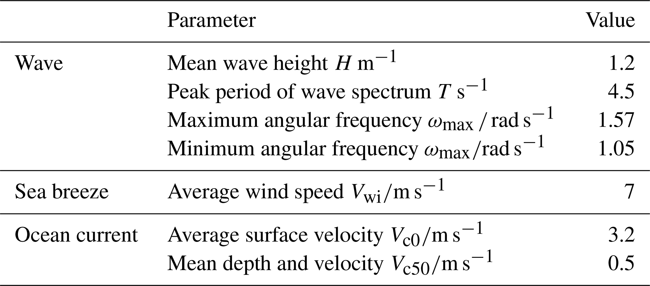
To analyze and compare the energy efficiency characteristics of the two energy conversion systems, and further determine the best energy efficiency parameters of the energy conversion system, this paper selected Ansys AQWA (Yao et al., 2021), for the fluid dynamics analysis. The hydrodynamic parameters were selected from the environmental data of the South China Sea (Cong et al., 2018), as shown in Table 1.
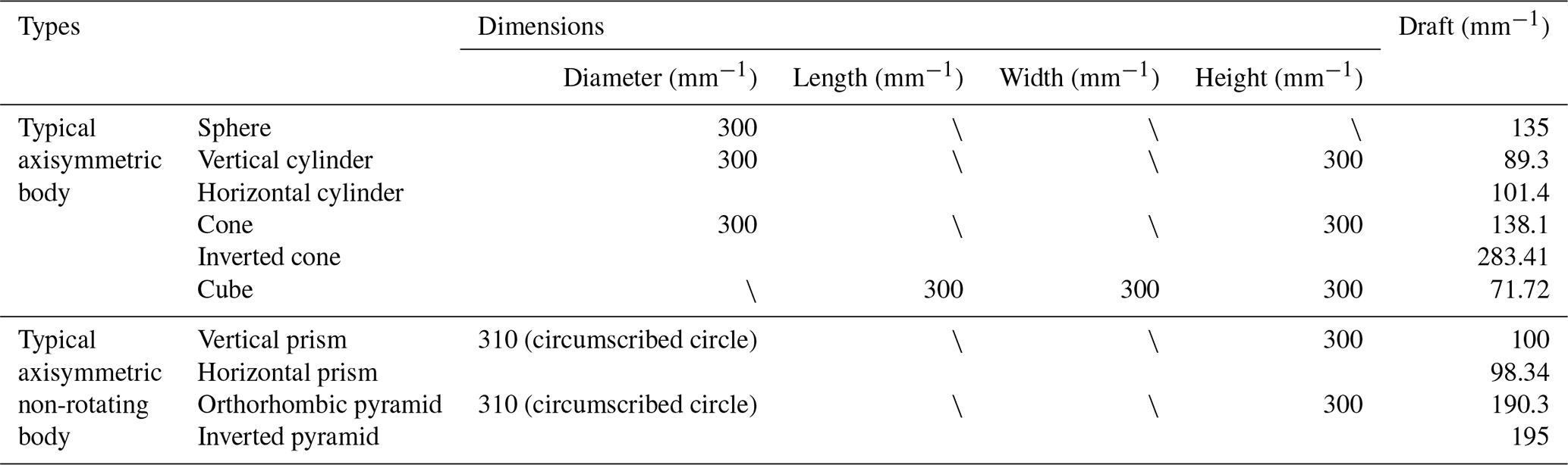
At the same time, to ensure that other parameters have the least influence on the parameters to be analyzed in the comparative analysis of the results, according to the actual dimensions of the low-power unoccupied marine equipment, the space dimension of the floating body was limited to 300 mm × 300 mm × 300 mm. In this limited range of the spatial scale, the scale of each floating body was maximized. Polystyrene foam (EPS foam) was used as the material for the floater manufacture. Its density was 25 kg m−3, and its maximum water absorption was only 4 % of the volume. According to the relevant engineering research, the mass of the underwater absorber was 5.78 kg (Cong et al., 2018; Sun et al., 2018) The typical types and characteristic parameters of all different parameters and shapes are shown in Table 2.
Table 2Typical types and characteristic parameters of floating bodies on the water surface.
3.1 Energy efficiency characteristics of axisymmetric and non-axisymmetric floating bodies
Numerical calculation and comparative analysis were carried out for the RAO, radiation damping, added mass and Froude–Krylov force of the spherical and square, cylindrical and prismatic, conical and pyramid floating bodies, respectively. The comparison results of energy efficiency are shown in Figs. 3–5 and Tables 3–4.

Figure 3Energy efficiency comparison of spherical and square floating bodies. (a) RAOs. (b) Radiation damping. (c) Added mass. (d) Froude–Krylov force.
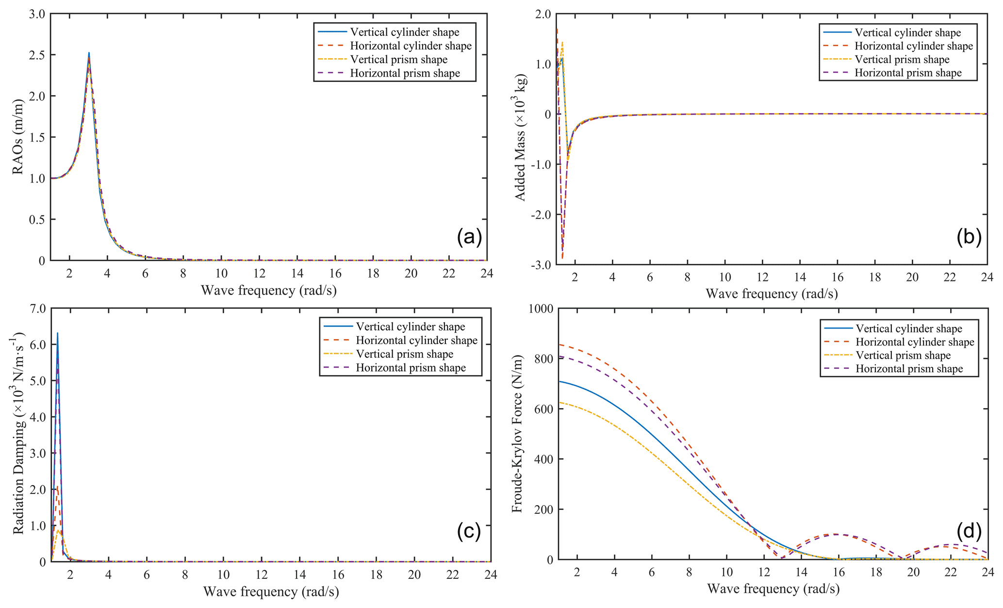
Figure 4Energy efficiency comparison of cylinder and prism floating bodies. (a) RAOs. (b) Radiation damping. (c) Added mass. (d) Froude–Krylov force.
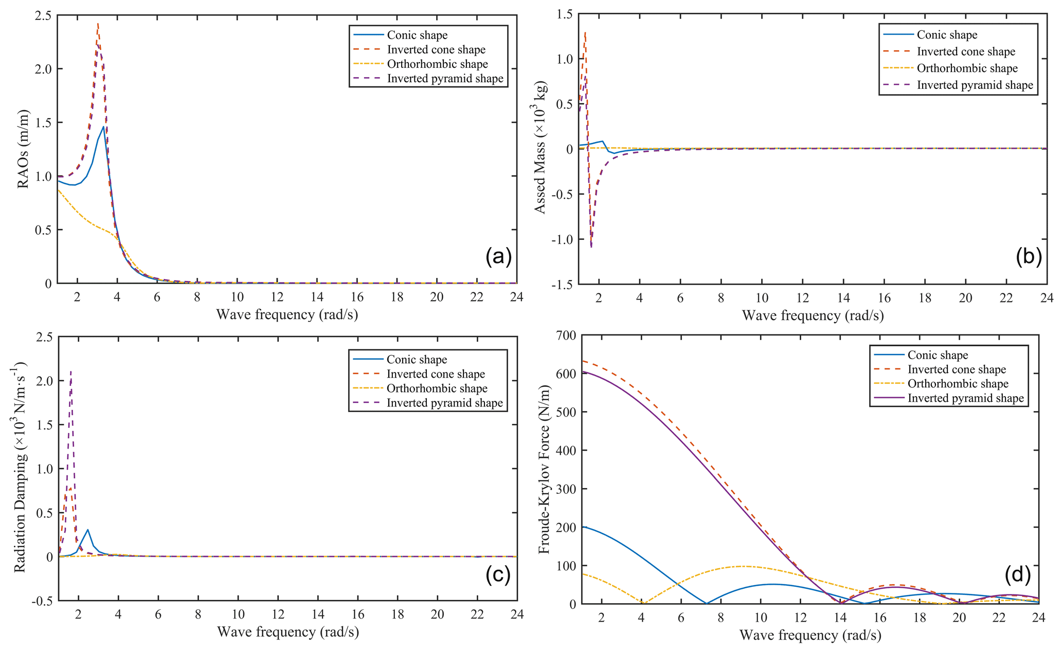
Figure 5Energy efficiency comparison of cone and pyramid floating bodies. (a) RAOs. (b) Radiation damping. (c) Added mass. (d) Froude–Krylov force.
Table 3Comparison of the energy efficiency between cylindrical and prismatic floating bodies with different postures.
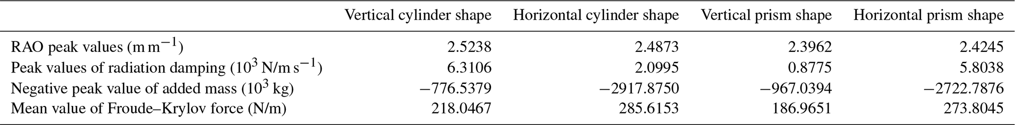
Table 4Comparison of the energy efficiency between conical and pyramid floating bodies with different postures.

Figure 3 shows the energy efficiency comparison results of the spherical and square floating bodies. It can be seen that the energy efficiency results of the two shapes show similar behaviors, but it changes with the shape. The RAO peak and RAO average values of the spherical floating body are 14.45 % and 1.42 % higher than that of square floating body, and the peak and average values of the radiation damping of spherical floating body are 40.59 % and 21.54 % higher than that of square floating body. The peak value of the added mass of the square floating body is 5.03 % higher than that of the spherical floating body, and the peak and average values of the Froude–Krylov force are 28.77 % and 29.59 % higher than those of spherical floating body. According to Eq. (6), under the limitation of the spatial scale, the conversion efficiency of the largest-scale spherical floating body is better than that of the largest-scale square floating body under the same sea conditions and material.
Figure 4 and Table 3 show the energy efficiency comparison results of the cylindrical and prismatic floating bodies with different postures. It can be seen that all the results maintain a relatively similar behavior, but the values are different. The RAO peak values of vertical cylindrical floating body are 1.47 %, 5.33 % and 4.10 % higher than that of horizontal cylindrical, vertical prismatic and horizontal prismatic, respectively. The peak values of the radiation damping are 200.58 %, 619.18 % and 8.73 % higher than that of the horizontal cylindrical, vertical prismatic and horizontal prismatic, respectively. The negative peak value of the added mass of horizontal cylindrical floating body is 275.75 %, 201.73 % and 7.17 % higher than that of vertical cylindrical floating body, vertical prismatic floating body and horizontal prismatic floating body, respectively. The mean value of the Froude–Krylov force is 30.99 %, 52.76 % and 4.31 % higher than that of vertical cylindrical floating body, vertical prismatic floating body and horizontal prismatic floating body. According to Eq. (6), under the limitation of the spatial scale, the conversion efficiency of the largest-scale vertical cylindrical floating body is better than that of the largest-scale horizontal prismatic floating body, followed by vertical prismatic floating body and horizontal cylindrical floating body.
Figure 5 and Table 4 show the energy efficiency comparison results of the conical and pyramid floating bodies with different postures. It can be seen that all the results have poor similarity. The RAO peak value of the inverted cone floating body is 65.66 %, 178.09 % and 8.80 % higher than that of the inverted cone type, the inverted pyramid type and the inverted pyramid type, respectively, and the peak value of the added mass amplitude is 1453.55 %, 14105.57 % and 61.95 % higher than that of the inverted cone type, the inverted pyramid type and the inverted pyramid type, respectively, with 87 %, 394.14 % and 5.39 %, respectively. The peak value of the radiation damping of the inverted pyramid floating body is 587.82 %, 170.07 % and 8894.55 % higher than that of the normal pyramid floating body, normal pyramid floating body and inverted pyramid floating body, respectively. According to Eq. (6), under the limitation of the spatial scale, the conversion efficiency of the largest-scale inverted cone floating body is better than that of the largest-scale inverted pyramid floating body under the same sea conditions and material, followed by the regular cone floating body and regular pyramid floating body.
3.2 Energy efficiency characteristics of various floating bodies with an axisymmetric revolving body
It can be seen, from Sect. 3.1, that the conversion efficiency of the axisymmetric revolving floating body (sphere, vertical cylinder and inverted cone) is better than that of corresponding axisymmetric non-revolving floating body. Therefore, to explore the optimal shape of the axisymmetric rotary body, the numerical calculation and comparative analysis of the RAO, radiation damping, additional mass, Froude–Krylov force and conversion energy efficiency of the sphere, vertical cylinder and inverted cone are carried out, respectively. The comparison results of energy efficiency are shown in Fig. 6.
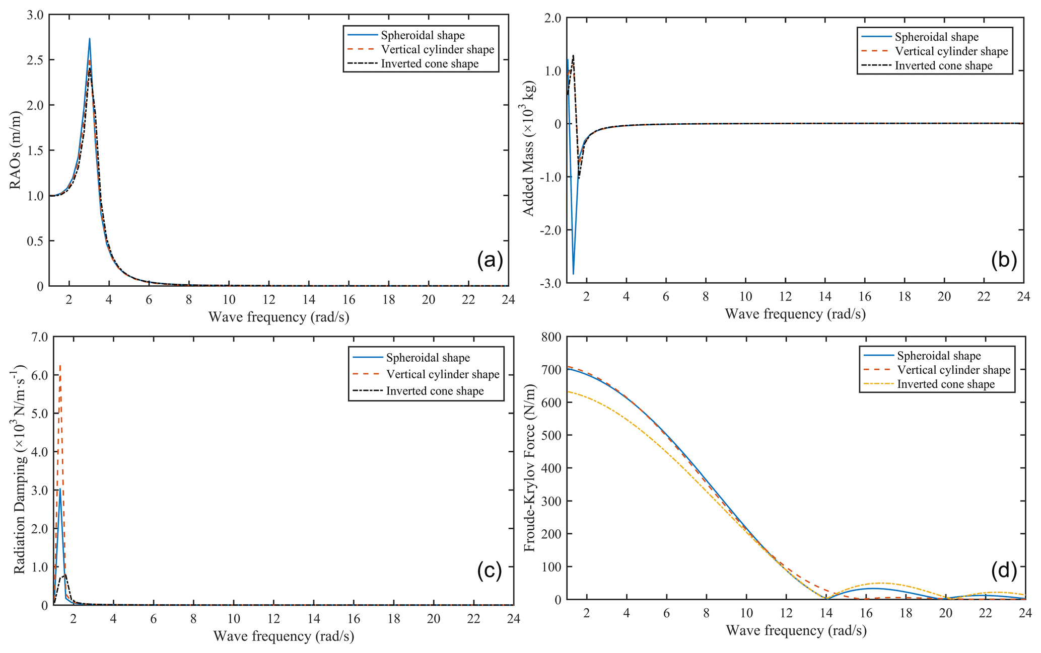
Figure 6Energy efficiency comparison of floating bodies with the multi-type axisymmetric rotating type. (a) RAOs. (b) Radiation damping. (c) Added mass. (d) Froude–Krylov force.
Figure 6 shows that the variation curves of the RAO, radiation damping, added mass and Froude–Krylov force of the three axisymmetric floating bodies are basically the same. The RAO amplitude of the sphere is larger than that of the vertical cylinder, followed by the inverted cone. The radiation damping amplitude of the vertical cylinder is larger than that of the sphere, followed by the inverted cone. The added mass amplitude of inverted cone is larger than that of sphere, followed by that of vertical cylinder. The Froude–Krylov force amplitude of the vertical cylinder is larger than that of the sphere, followed by the inverted cone. According to Eq. (6), under the limitation of the spatial scale, the energy efficiency conversion ratio of the spherical floating body with the same sea conditions, the same material and the largest scale in the heave motion mode is 1.3 %, the vertical cylinder is 1.25 % and the inverted cone is 1.12 %. Therefore, the conversion efficiency performance of the above three axisymmetric floating bodies is the best, followed by the vertical cylinder and inverted cone.
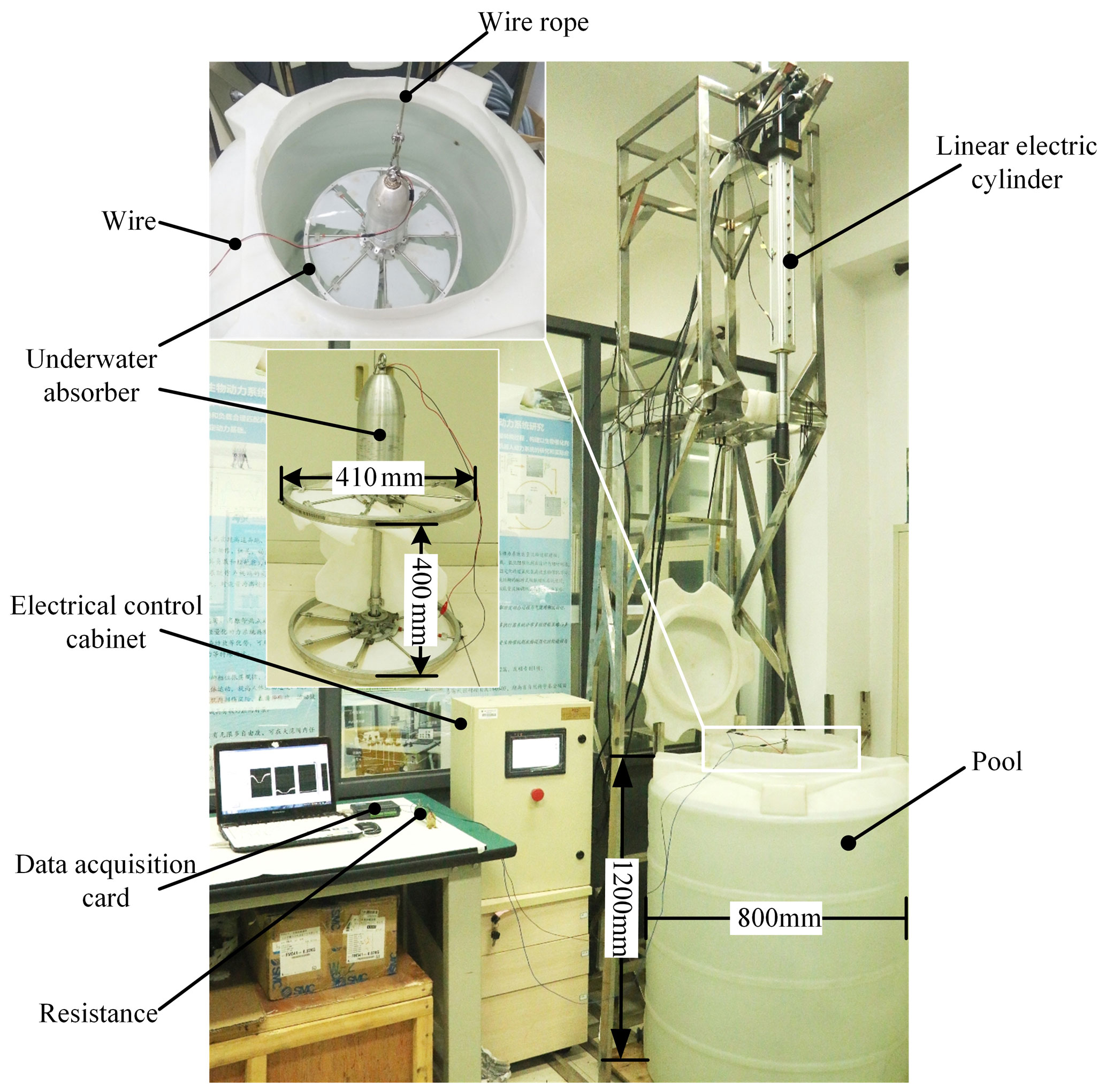
To verify the correctness and feasibility of the comparison results, Fig. 7 shows an experimental test platform in the laboratory. The platform is composed of a water tank, linear electric cylinder, steel cable, wire, control cabinet, data acquisition card, resistance and upper computer with a data acquisition program. The height of the water tank is 1.2 m, and the diameter of water tank is 0.8 m. The control cabinet controls the linear electric cylinder to move up and down, according to the period and stroke of the sine wave linear motion, and drives the underwater absorber to move up and down vertically. Due to the limitation of the working stroke and feedback speed of the linear electric cylinder, the minimum period of the experimental system is set as 1.5 s, and the maximum amplitude is set as 150 mm. The experimental system uses data acquisition card (DAQ Navi USB-4716) to collect data. Due to the limitation of the measurement range of the data acquisition card, the measurement range of the voltage signal in the experiment is ( 10 V). At the same time, the 30 Ω sliding resistance is selected as the experimental load.
In addition, Fig. 7 shows the experimental model and installation position of the underwater absorber, with a diameter of 410 mm and a height of 400 mm. The top of the underwater absorber is connected with the end of the push rod of the linear electric cylinder by a steel cable. A DC generator with a built-in speed increaser is integrated into the PTO. The maximum output power of DC generator is 30 W.
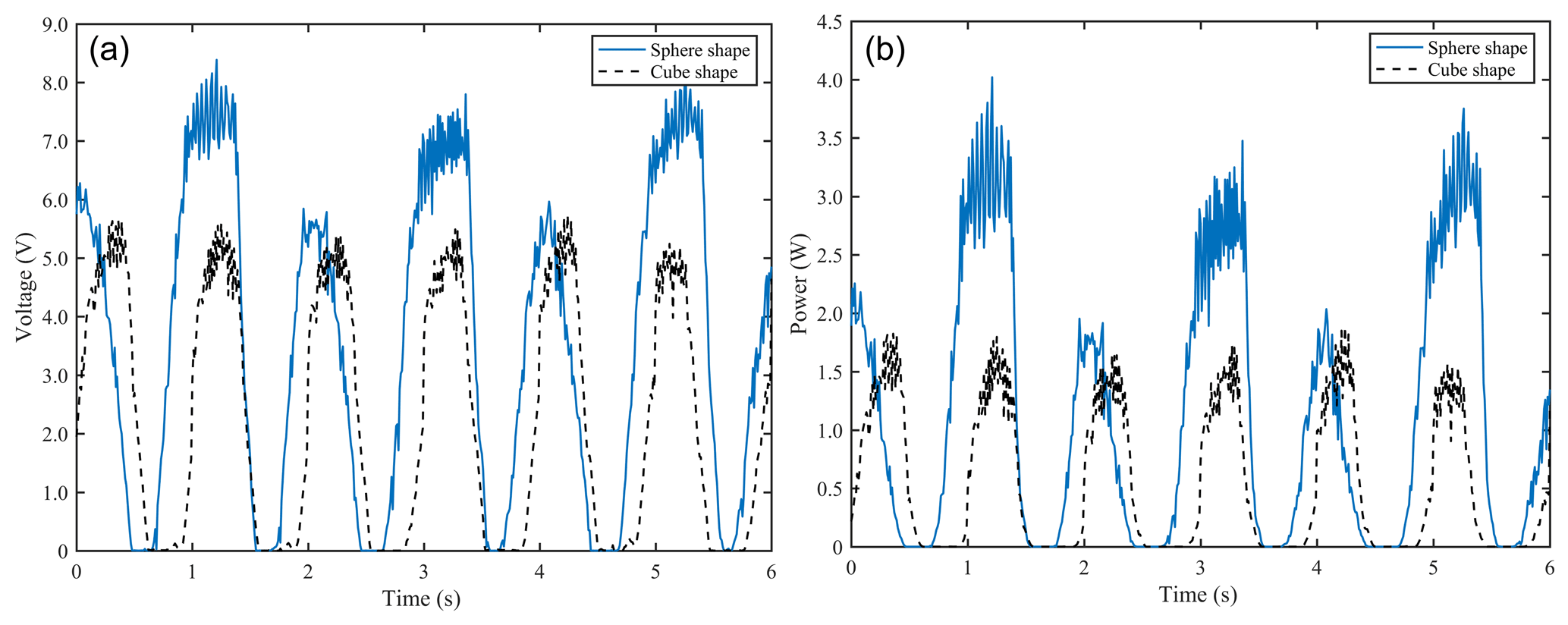
Figure 8Energy efficiency characteristic curves of the spherical and square floating bodies. (a) Voltage curve. (b) Power curve.
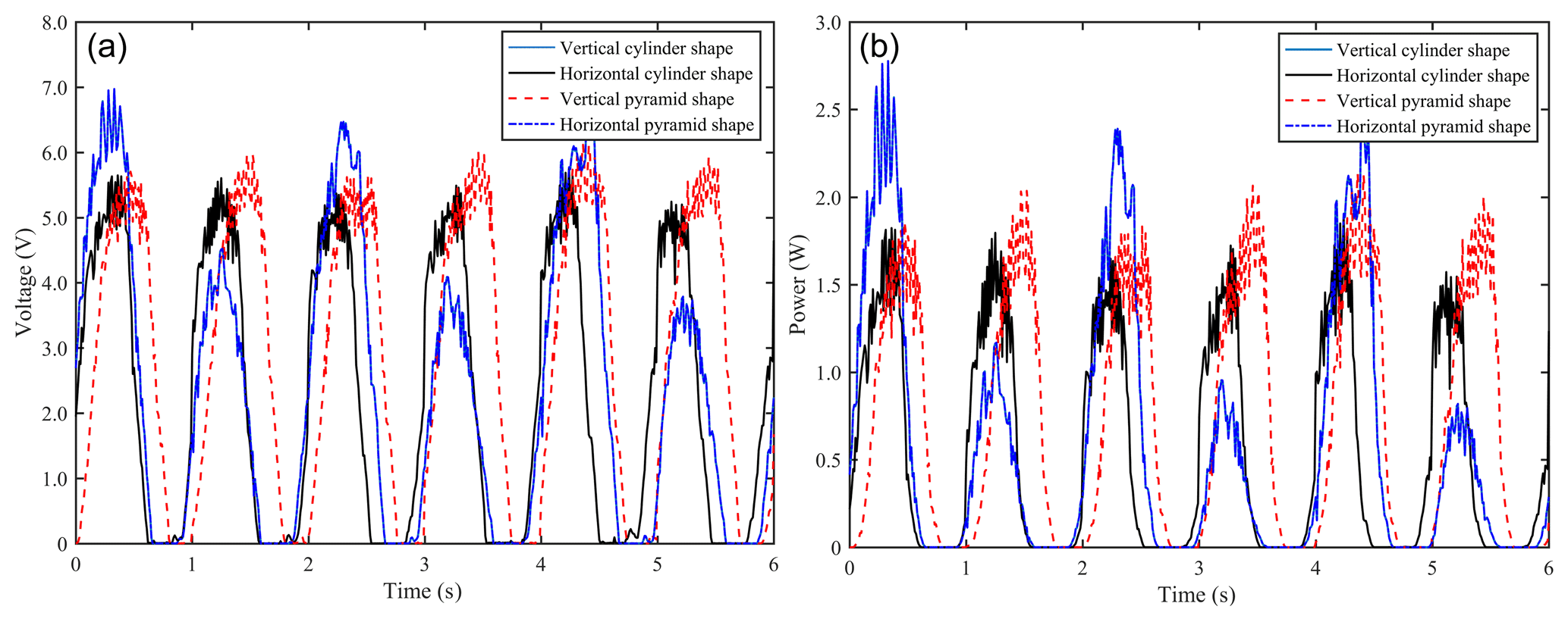
Figure 9Energy efficiency characteristic curves of the cylindrical and prismatic floating bodies. (a) Voltage curve. (b) Power curve.
In the experimental environment, the energy efficiency conversion of the system was verified by the output power and output voltage of the PTO system of the underwater absorber. Under the same sea conditions of the numerical simulation, the energy efficiency characteristics of axisymmetric bodies of a revolution (spheres, cylinders, cones, etc.) and axisymmetric non-bodies of a revolution (cubes, prisms, pyramids, etc.) were tested on the experimental platform.

Figure 10Energy efficiency characteristic curves of the conical and pyramid floating bodies. (a) Voltage curve. (b) Power curve.
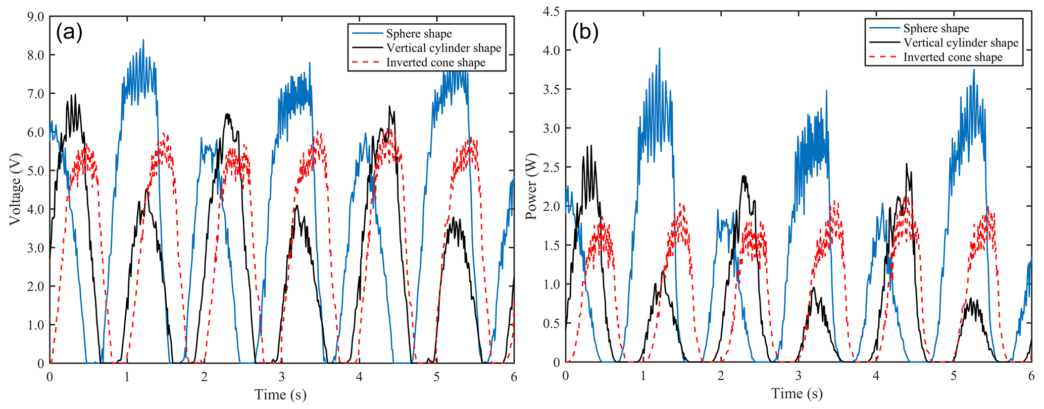
Figure 11Energy efficiency characteristic curves of various axisymmetric floating bodies. (a) Voltage curve. (b) Power curve.
Figure 8 shows the energy efficiency characteristic curve of the PTO system matching the spherical and square floating bodies. Figure 8 shows the output voltage and output power of the PTO system of the underwater absorber matched with the spherical and square floating bodies under the same sea conditions, the same material and the largest scale in the limited range of the spatial scale. The output voltage of the PTO system of the underwater absorber matched with the spherical floating body is about 8 V, and the output power is about 3.7 W. The output voltage and power of the PTO system are 5.62 V and 1.82 W, respectively. It can be seen that the conversion efficiency of the largest-scale spherical floating body is better than that of the largest-scale square surface floating body in the limited range of the spatial scale.
Figure 9 shows the energy efficiency characteristic curve of the PTO system matching the cylindrical and prismatic floating bodies. Figure 9 shows the output voltage and output power of the PTO system of the underwater absorber matched with the cylindrical and prismatic floating bodies under the same sea conditions, the same material and the largest scale in the limited range of the spatial scale. The output voltage and power of the PTO system are 6.9 V and 2.73 W, respectively. The output voltage and power of the PTO system are 5.62 V and 1.82 W, respectively. The output voltage and power of the PTO system are 5.9 V and 2.1 W, respectively. The output voltage of the PTO system of the underwater absorber matched with the horizontal prism-type floating body is approximately 6.7 V, and the output power is about 2.7 W. It can be seen that the conversion efficiency of the largest-scale vertical cylindrical floating body is better than that of the largest-scale horizontal prismatic floating body, vertical prismatic floating body and horizontal cylindrical floating body.
Figure 10 shows the energy efficiency characteristic curve of the PTO system matching the cone and pyramid floating bodies. Figure 10 shows the output voltage and output power of the PTO system of the underwater absorber matched with the conical and pyramid floating bodies in the limited range of the spatial scale, where the same sea conditions, the same material and the largest scale are also obvious. The simulated amplitude of the square pyramid floating body in the experimental platform for the energy efficiency test of the heave wave energy generation device is 47.7 mm. Because of its short stroke, the amplitude is basically zero, and the output voltage and power are almost zero. The output voltage of the PTO system is about 4.5 V and the output power is about 1.18 W. The output voltage of the PTO system of the underwater absorber matching the inverted cone floating body is approximately 5.9 V, and the output power is approximately 2.1 W. The output voltage and power of the PTO system of the underwater absorber matched with the inverted pyramid floating body are approximately 4.9 V and 1.4 W, respectively. It can be seen that the conversion efficiency of the largest-scale inverted pyramid floating body is better than that of the largest-scale inverted pyramid floating body, the right cone floating body and the right pyramid floating body under the same sea conditions and material.
Figure 11 shows the energy efficiency characteristic curve of the PTO system for three kinds of axisymmetric surface floating bodies. The results show that the output voltage and output power of the PTO system of the underwater absorber matched with three kinds of axisymmetric surface floating bodies, i.e., sphere, vertical cylinder and inverted cone, change obviously under the same sea conditions, the same material and the largest scale. The output voltage of the PTO system of the underwater absorber matched with the spherical floating body is about 8 V, and the output power is about 3.7 W. The output voltage and power of the PTO system matched with the vertical cylindrical floating body are about 6.9 V and 2.73 W, respectively. The output voltage and power of the PTO system of the underwater absorber matched with the inverted conical floating body are approximately 5.9 V and 2.1 W, respectively. It can be seen that the conversion efficiency of spherical floating body with the largest scale is better than that of vertical cylindrical floating body with the largest scale and the inverted cone floating body with the same sea conditions and material.
In this paper, the structure of the multi-body heave wave energy conversion systems was firstly designed, and the dynamic model and the energy efficiency evaluation mathematical model of water surface floating body were established. Then, the energy efficiency characteristics of different shapes of water surface floating bodies were analyzed and compared. Finally, the optimal efficiency shape of water surface floating body was explored. The conclusions are as follows:
-
Under the limitation of the low power consumption and space scale of unoccupied marine equipment, the largest-scale axisymmetric water surface floating body (sphere, vertical cylinder and inverted cone) with the same sea conditions and material can improve the conversion efficiency of the new multi-body heave wave energy conversion system.
-
Among the three axisymmetric floating bodies, the sphere is the best, followed by the vertical cylinder and the inverted cone, but there is little difference among them.
-
The experimental results of energy efficiency characteristics are consistent with the simulation results in the comparison of energy efficiency of different types of energy conversion systems, which verifies the feasibility and correctness of the conclusion.
| z1 | Displacement responses of the upper floating structures |
| z2 | Displacement responses of the lower floating structures |
| Corresponding acceleration responses | |
| m1 | Masses of the upper floating bodies |
| m2 | Masses of the lower floating bodies |
| c1 | The linear damping coefficients of the upper floating bodies |
| c2 | Linear damping coefficients of the lower floating bodies |
| cpto | Linear damping coefficient of the PTO system |
| k1 | Linear stiffness coefficients of the upper floating bodies |
| k2 | Linear stiffness coefficients of the lower floating bodies |
| k | Wave number |
| ηEnergy | Energy efficiency conversion ratio of surface floating body |
| Eabs | Total energy of waves |
| ρ | Density of the sea water |
| λ | Wave length |
| Awp | Cross-sectional area of the floating body |
| ξi | Motion amplitude of floating body on water surface |
| A | Linear incident wave amplitude |
| H | Wave height |
| x | Direction of wave propagation in the global coordinate system |
| Horizontal displacement of the floating body in the local coordinate system | |
| d | Water depth |
| F1 | Total forces on the upper floating bodies |
| F2 | Total forces on the lower floating bodies |
| ma1 | Added mass of the upper floating body |
| ca1 | Damping of the upper floating body |
| ma2 | Added mass of the lower floating body |
| ca2 | Damping of the lower floating body |
| M | Mass matrix |
| C | Linear damping matrix |
| K | Linear stiffness matrix |
| Ma | Added mass matrix of PTO system |
| Ca | Radiation damping matrix of PTO system |
| Cpto | Linear damping matrix of PTO system |
| Fe | Wave exciting force matrix |
| Fhys | Hydrostatic restoring force matrix |
| G | Gravity matrix |
| c | Diffraction correction coefficient |
| FFKdy | Dynamic Froude–Krylov force |
| FD | Diffraction force |
| S | Wet surface area of the floating body |
| n | Normal of the wet surface of the floating body |
| Pdy | Dynamic pressure |
| ω | Wave circle frequency |
All data included in this study are available upon request from the corresponding author.
DC conceived the idea, developed the method, performed experiments and simulations, and wrote the majority of the paper. HJ, RZ, ZhL and JS supervised and structured the paper. DC edited the paper, HJ and ZiL corrected the paper.
The contact author has declared that neither they nor their co-authors have any competing interests.
Publisher's note: Copernicus Publications remains neutral with regard to jurisdictional claims in published maps and institutional affiliations.
This study has been funded by the Shandong Province Nature Science Foundation, China (grant no. ZR2019PEE020), the National Natural Science Foundation, China (grant no. 52075537), and the Key Research Development Project of Guangzhou Province, China (grant no. 2020B1111030002). The authors sincerely thank the editors and reviewers, for their insight and comments which further improved the quality of this paper.
This research has been supported by the Shandong Province Nature Science Foundation, China (grant no. ZR2019PEE020), the National Natural Science Foundation, China (grant no. 52075537), and the Key Research Development Project of Guangzhou Province, China (grant no. 2020B1111030002).
This paper was edited by Guowu Wei and reviewed by two anonymous referees.
Babarit, A., Clement, A. H., and Gilloteaux, J. C.: Optimization and time-domain simulation of the SEAREV wave energy converter, in: Proceedings of 24th International Conference Offshore Mechanics Arctic Engineering, Halkidiki, Greece, 1 January 2005, 703–712, 2005.
Banazadeh, A., Seif, M. S., and Kahodaei, M. J.: Identification of the equivalent linear dynamics and controller design for an unmanned underwater vehicle, Ocean Eng., 139, 152–168, 2017.
Bertaska, I. R. and Ellenrieder, K. D. V.: Experimental evaluation of supervisory switching control for unmanned surface vehicles, IEEE J. Oceanic Eng., 99, 1–22, 2018.
Bildirici, M. E. and Gökmenoğlu, S. M.: Environmental pollution, hydropower energy consumption and economic growth: evidence from G7 countries, Renew. Sust. Energ. Rev., 75, 68–85, 2017.
Blazquez, J., Fuentes-Bracamontes, R., Bollino, C. A., and Nezamuddin, N.: The renewable energy policy paradox, Renew. Sust. Energ. Rev., 82, 1–5, 2018.
Chiba, S., Waki, M., and Wada, T.: Consistent ocean wave energy harvesting using electroactive polymer (dielectric elastomer) artificial muscle generators, Appl. Energ., 104, 497–502, 2013.
Clemente, D., Rosa-Santos, P., and Taveira-Pinto, F.: On the potential synergies and applications of wave energy converters: A review, Renew. Sust. Energ. Rev., 135, 110162, https://doi.org/10.1016/j.rser.2020.110162, 2021.
Cong, D. S., Shang, J. Z., and Luo, Z. R.: Energy Efficiency Analysis of Multi-Type Floating Bodies for a Novel Heaving Point Absorber with Application to Low-Power Unmanned Ocean Device, Energies, 11, 3284, https://doi.org/10.3390/en11123282, 2018.
Cruz, J. and Atcheson, M.: Floating offshore wind energy: the next generation of wind energy, Springer International Publishing, https://doi.org/10.1007/978-3-319-29398-1, 2016.
Cruz, J., Salter, S., and Thomas, G.: Ocean wave energy, Springer Berlin, 144, 2451–2460, https://doi.org/10.1007/978-3-540-74895-3, 2008.
Cuadra, L., Salcedo-Sanz, S., and Nieto-Borge, J. C.: Computational intelligence in wave energy: Comprehensive review and case study, Renew. Sust. Energ. Rev., 58, 1223–1246, 2016.
Fadaeenejad, M., Shamsipour, R., Rokni, S. D., and Gomes, C.: New approaches in harnessing wave energy: With special attention to small islands, Renew. Sust. Energ. Rev., 29, 345–354, 2014.
Giorgi, G. and Ringwood, J. V.: Computationally efficient nonlinear Froude-Krylov force calculations for heaving axisymmetric wave energy point absorbers, Journal of Ocean Engineering and Marine Energy, 3, 21–33, 2017.
Kabir, E., Kumar, P., Kumar, S., Adelodun, A. A., and Kim, K. H.: Solar energy: potential and future prospects, Renew. Sust. Energ. Rev., 82, 894–900, 2018.
Kaldellis, J. K. and Apostolou, D.: Life cycle energy and carbon footprint of offshore wind energy. Comparison with onshore counterpart, Renew. Energ., 108, 72–84, 2017.
Kannan, N. and Vakeesan, D.: Solar energy for future world: a review, Renew. Sust. Energ. Rev., 62, 1092–1105, 2016.
Kumar, Y., Ringenberg, J., and Depuru, S. S.: Wind energy: trends and enabling technologies, Renew. Sust. Energ. Rev., 53, 209–224, 2016.
Mendez, A., Leo, T. J., and Herreros, M. A.: Current state of technology of fuel cell power systems for autonomous underwater vehicles, Energies, 7, 4676–4693, 2014.
Moriarty, P. and Honnery, D.: Can renewable energy power the future?, Energ. Policy, 93, 3–7, 2016.
Mousazadeh, H., Jafarbiglu, H., and Abdolmaleki, H.: Developing a navigation, guidance and obstacle avoidance algorithm for an unmanned surface vehicle (USV) by algorithms fusion, Ocean Eng., 159, 56–65, 2018.
Noren, S. A.: Plant for utilizing kinetic energy, US Patents: 4277690, 1981.
Sampaio, P. G. V. and González, M. O. A: Photovoltaic solar energy: conceptual framework, Renew. Sust. Energ. Rev., 74, 590–601, 2017.
Serrano-González, J. and Lacal-Arántegui, R.: Technological evolution of onshore wind turbinesa market-based analysis, Wind Energy, 19, 2171–2187, 2016.
Seyedeh, F. N., Anooshiravan, F., and Aref, A.: Novel piezoelectric-based ocean wave energy harvesting from offshore buoys, Appl. Ocean Res., 76, 174–183, 2018.
Sun, C. F., Luo, Z. R., and Shang, J. Z.: Design and Numerical Analysis of a Novel Counter-Rotating Self-Adaptable Wave Energy Converter Based on CFD Technology, Energies, 11, 694, https://doi.org/10.3390/en11040694, 2018.
Trainer, T.: Some problems in storing renewable energy, Energ. Policy, 110, 386–393, 2017.
Venkatesan, R., Sannasiraj, S. A., and Ramanamurthy, M. V.: Development and performance validation of a cylindrical buoy for deep-ocean tsunami monitoring, IEEE J. Oceanic Eng., 99, 1–9, 2018.
Wang, X. M.: Study on micro scale wave energy absorption mechanism and conversion system based on buoy's rolling motion, PhD, National Defense University of science and technology, 2–3, 2013.
Weber, J., Mouwen, F., and Robertson, D.: Wavebob-research & development network and tools in the context of systems engineering, in: Proceedings of the 8th European Wave and Tidal Energy Conference, Uppsala, Sweden, 2009.
Yao, T., Wang, Y., Wang, Z., and Qin, C.: Design and performance analysis of wave linear generator with parallel mechanism, Mech. Sci., 12, 405–417, https://doi.org/10.5194/ms-12-405-2021, 2021.
Zarfl, C., Lumsdon, A. E., Berlekamp, J., Tydecks, L., and Tockner, K.: A global boom in hydropower dam construction, Aquat. Sci., 77, 161–170, 2015.
Zhang, D. H., Li, W., Lin, Y. G., and Bao, J. W.: An overview of hydraulic systems in wave energy application in China, Renew. Sust. Energ. Rev., 16, 4522–4526, 2012.
Zoss, B. M., Mateo, D., and Kuan, Y. K.: Distributed system of autonomous buoys for scalable deployment and monitoring of large waterbodies, Auton. Robot., 11, 1–21, 2018.
- Abstract
- Introduction
- Multi-body heave wave energy conversion system
- Comparative analysis and discussion
- Energy efficiency characteristic test
- Conclusions
- Appendix A: List of symbols.
- Data availability
- Author contributions
- Competing interests
- Disclaimer
- Acknowledgements
- Financial support
- Review statement
- References