the Creative Commons Attribution 4.0 License.
the Creative Commons Attribution 4.0 License.
 | 29 Apr 2022
Design of a transrectal ultrasonic guided prostate low dose rate brachytherapy robot
Xuesong Dai
Yongde Zhang
Jingang Jiang
Bing Li
Sihao Zuo
Transrectal prostate brachytherapy (BT) can effectively treat prostate cancer. During the operation, doctors need to hold the ultrasound probe for repeated adjustments, which makes it difficult to ensure the efficiency, accuracy, and safety of the operation. We designed an 11 DOF (degrees of freedom) active and passive transrectal BT robot, based on the analysis of the transrectal prostate BT process. The posture adjustment module designed, based on the double parallelogram mechanism, realizes the centering function of the ultrasound probe and performs the kinematic analysis. Based on Simscape Multibody, the working posture and centering effect of the ultrasound probe's different feed distances are simulated. A physical prototype of the transrectal BT robot was developed and measured in experiments. The experimental results indicate that the angle rotation error of the joint is controlled to within 1∘. The rotation range of each joint meets the design requirements. The maximum error of the yaw angle's remote center point motion and pitch angle's remote center point motion are 0.5 and 0.4 mm, respectively, which are less than the deformation that can be endured in the anus by 6 mm. The simulation and experimental results and the analysis of measurement errors have verified the effectiveness and stability of the transrectal BT robot.
- Article
(14584 KB) - Full-text XML
- BibTeX
- EndNote


Prostate cancer is the second most common cancer worldwide and the sixth leading cause of cancer deaths in men worldwide, with an estimated 1 276 000 new cancer cases and 359 000 deaths in 2018 (Culp et al., 2020). Low dose rate brachytherapy (BT) has higher efficacy and safety than external beam radiotherapy and prostatectomy. The use of BT in prostate cancer treatment is increasing every year (Corkum et al., 2020). In recent years, many researchers have designed ultrasound-guided robots to assist urologists in seed implantation (Halima et al., 2021; Chen et al., 2017; Djohossou, 2019; Fichtinger et al., 2006, 2008; Lagerburg et al., 2006; Rivard et al., 2005; Wei et al., 2005; Yongde et al., 2015; Yu et al., 2007; Zhang et al., 2015). Parallel needle insertion robots, which were developed in previous research (Lagerburg et al., 2006; Rivard et al., 2005; Wei et al., 2005), cannot puncture the prostate tissue behind the pubic bone if the patient's prostate is large (>60 cm3). The literature (Chen et al., 2017; Djohossou, 2019; Fichtinger et al., 2008) have discussed the development of a prostate BT robot that can perform angled needle insertion to puncture the prostate behind the pubic bone. However, this increases the size of the robot and the complexity of control. Currently, all prostate BT robots adopt the transperineal approach for needle insertion.
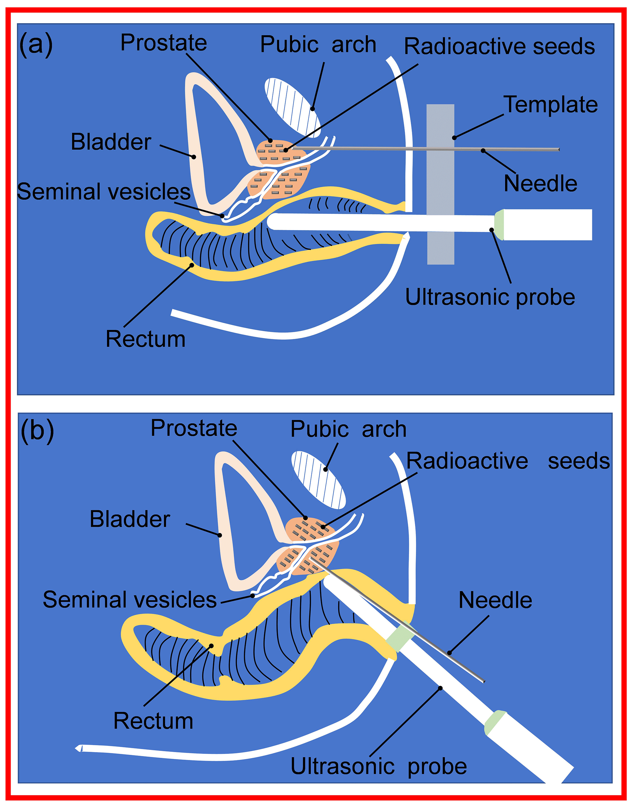
Clinically, there are two needle insertion routes for prostate BT, namely transperineal BT and transrectal BT (Xin et al., 2018), as presented in Fig. 1. Compared with transperineal BT, transrectal BT has the following three advantages: (1) no anesthesia is required (transperineal seed implantation requires general anesthesia, which increases the surgical risk for the elderly), (2) the needle insertion path is short, and the position accuracy of the needle tip and particle is high, and (3) the pubic arch will not block the needle insertion route. However, transrectal BT has the following disadvantages: the intraoperative urologist needs to hold the ultrasound probe for a long time, increasing the urologist's labor intensity, which in turn affects the BT accuracy (Dai et al., 2021).
As mentioned above, there is currently no transrectal prostate BT robot. Therefore, it is necessary to develop a corresponding transrectal BT robot to address the abovementioned problems. We designed a robot for transrectal prostate BT, which can effectively assist urologists in completing the transrectal prostate BT and conducting simulation experiments, physical prototype experiments, and measurement error analysis to verify its centering performance. The designed robot not only enables doctors to free their hands during the operation, but it also improves the efficiency and precision of the prostate BT.
2.1 Analysis of the ultrasound probe motion form
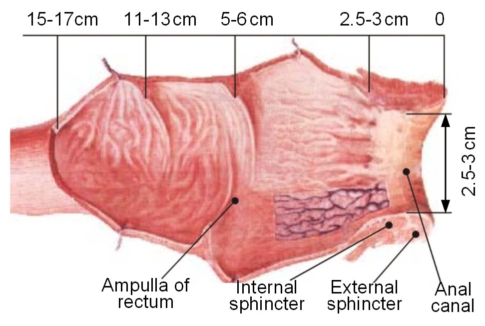
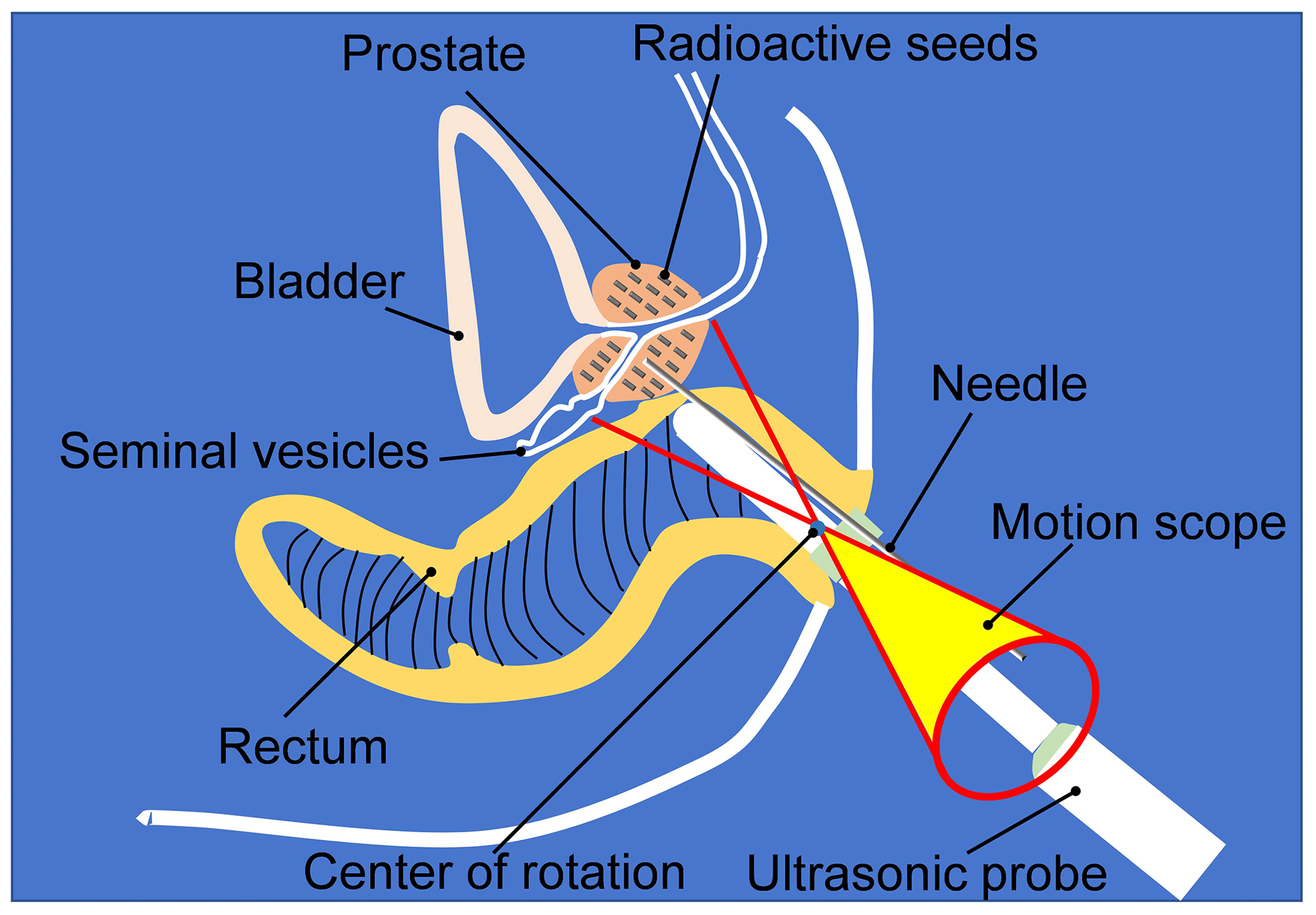
The prostate is located in the ampulla of the rectum. The upper end of the prostate is wide (approximately 40 mm in transverse diameter and 30 mm in vertical diameter), and the lower end is narrow and flat (approximately 25 mm in the front and rear diameter). After an edema, the volume of the prostate can increase to one-quarter of its original volume (Alberto et al., 2020). In the process of prostate BT, the ultrasound probe is inserted through the anus. The ultrasound probe needs to complete the adjustment of the position, yaw angle, and pitch angle and realize the rotation and feeding of the ultrasound probe to complete the multiangle and all-around prostate scanning. Figure 2 is an anatomical diagram of the rectum (Vaggers et al., 2020). It can be found that the space of the rectal ampulla is relatively large. In contrast, the internal anal sphincter's space is relatively narrow; therefore, the ultrasound probe needs to pass through the anal canal to reach the rectal ampulla. In this process, to avoid harm to the rectum and to reduce the patient's pain, the ultrasound probe should always swing around the center of the anus periphery as the center of rotation, and its range of motion is a cone-shaped space, as illustrated in Fig. 3.
2.2 Structural design
According to the above analysis of the motion form of the ultrasound probe, we divided the robot into three parts, i.e. the preoperative position adjustment module, a posture adjustment module, and an ultrasound probe with self-rotation and a feeding module. Urologists use the preoperative position adjustment module to adjust the ultrasonic probe to the appropriate position. The posture adjustment module is used to perform the yaw action and pitch action of the ultrasound probe. The ultrasound probe with self-rotation and a feeding module is used to perform the self-rotation and feeding motions of the ultrasound probe.
In order for urologists to facilitate the adjustment of the position of the ultrasound probe more flexibly and conveniently before surgery, we used a commercial 7 DOF (degrees of freedom) passive robotic arm as the preoperative position adjustment mechanism of the ultrasound probe.
2.2.1 Posture adjustment module
In order to realize that the ultrasound probe can make a fixed-point movement swinging in two directions around the peripheral central point of the anus, the remote center motion (RCM) mechanism was selected for the attitude adjustment mechanism. The remote center of the motion mechanisms currently used in minimally invasive surgery includes parallelogram mechanisms, spherical mechanisms, arc mechanisms, and triangular mechanisms. Since the posture adjustment module is located at the end of the position adjustment module, the remote center of the motion mechanism must be selected to be as high as possible, with high precision and light weight (Nguyen Phu et al., 2019). Through comparison, it is found that the RCM mechanism of the double parallelogram is the most suitable for the design requirements of this paper. Therefore, this paper adopts the RCM mechanism based on the double parallelogram to design the posture adjustment module. Figure 4 is the schematic diagram of the posture adjustment module, where the two parallelograms are □ACFD and □BCJI, respectively. In Fig. 4, a local coordinate system is established to describe the mechanism's parallel and centering characteristics.
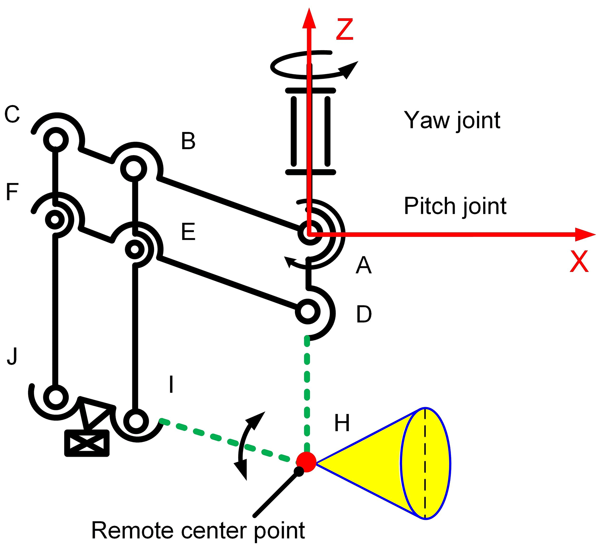
When the connecting rod (see Fig. 4), DF goes around D when the point is the center of the circle rotated by an angle and α, A, and B have the following characteristics:
-
parallel characteristics, where AD//BI//CJ, AC//DF//IJ, and
-
a centering characteristic, where the position of intersection H of extension line AD and extension line JI is always unchanged.
Generally, according to the human body's physiological characteristics, the prostate occupies a 40 mm × 30 mm × 25 mm rectangular parallelepiped. Figure 5 illustrates the prostate's spatial state when the patient is lying on the left side and shows the analysis of the swing angle of the ultrasound probe scanning the prostate. The yaw angle β is the swing angle of the ultrasound probe in the transverse section, and the pitch angle is the swing angle of the ultrasound probe in the longitudinal section. The distance from the center point H of the anus to the prostate surface HK is 60 mm. Considering that the volume of the prostate will increase by 25 % after the edema, when calculating the swing angle, the ultrasound probe takes the space volume of the prostate as 50 mm × 40 mm × 40 mm (Feng et al., 2009). Then, in the following:
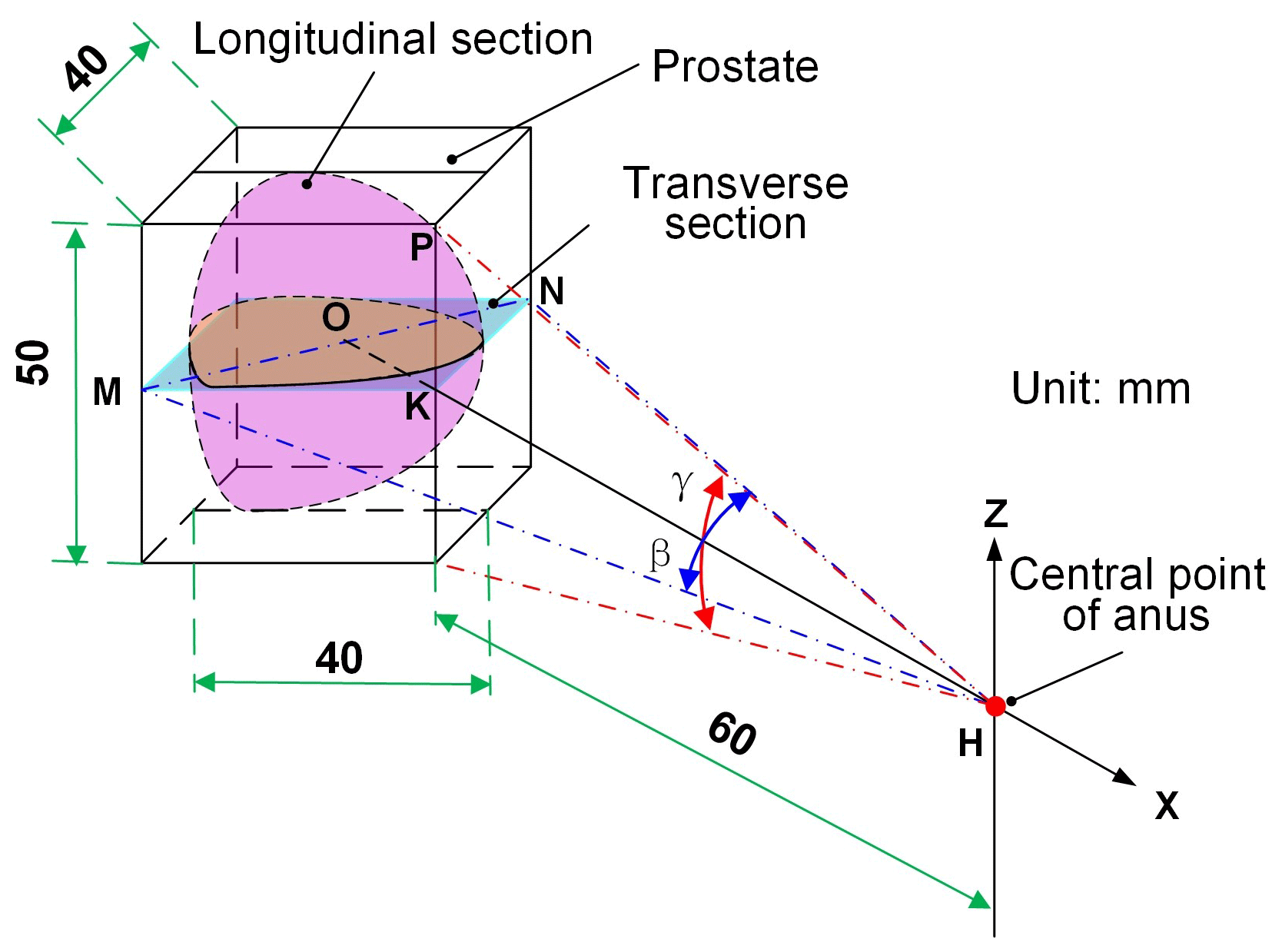
For the scanning range of the ultrasound probe to cover all the regions of the prostate, a β angle and a γ angle shall meet Eqs. (1) and (2) as follows:
where the solution is β≥35.4∘, γ≥45.3∘.
2.2.2 Ultrasound probe with self-rotation and a feed module
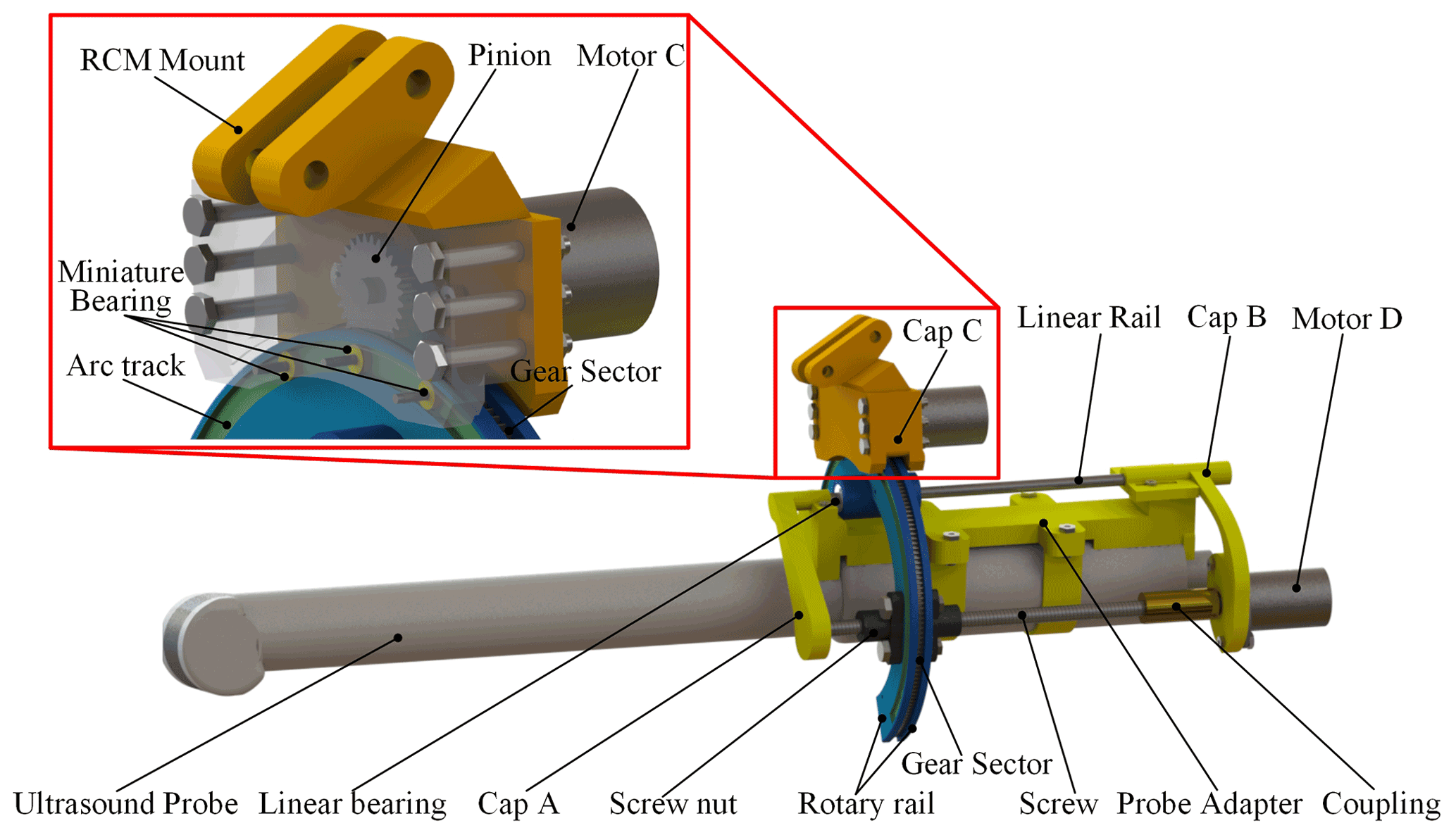
As illustrated in Fig. 6, the self-rotation and feed module of the ultrasound probe is connected with the RCM mechanism through the RCM mount. To enable the ultrasound probe to rotate coaxially with the rotation axis of this module, the ultrasound probe is fixed to an adapter. The adapter connects the module via cap A and cap B. Cap A and cap B are supported by a linear rail (diameter, 3 mm; chromium-plated 45 steel) and screw (T4 1; 304 stainless steel). A stepper motor D (CHS-GM15BY, 12 V, 3 W; transmission ratio of 1 : 380; Shenzhen Chihai Motor Co., Ltd.) drives the screw. The linear rail and the screw connect the horseshoe-shaped rotary rail through linear bearings and a screw nut. The horseshoe-shaped rotary rail achieves rotation through the meshing transmission of the sector gear and the pinion driven by the stepping motor C (CHS-GM15BY, 12 V, 3 W; transmission ratio of 1 : 380; Shenzhen Chihai Motor Co., Ltd.). The miniature bearings on the inside of cap C connect with the arc track to support the rotary rail. The purpose of selecting the horseshoe rotation rail is to allow sufficient puncture space for the BT needle above the ultrasound probe.
2.2.3 Overall structure of the robot
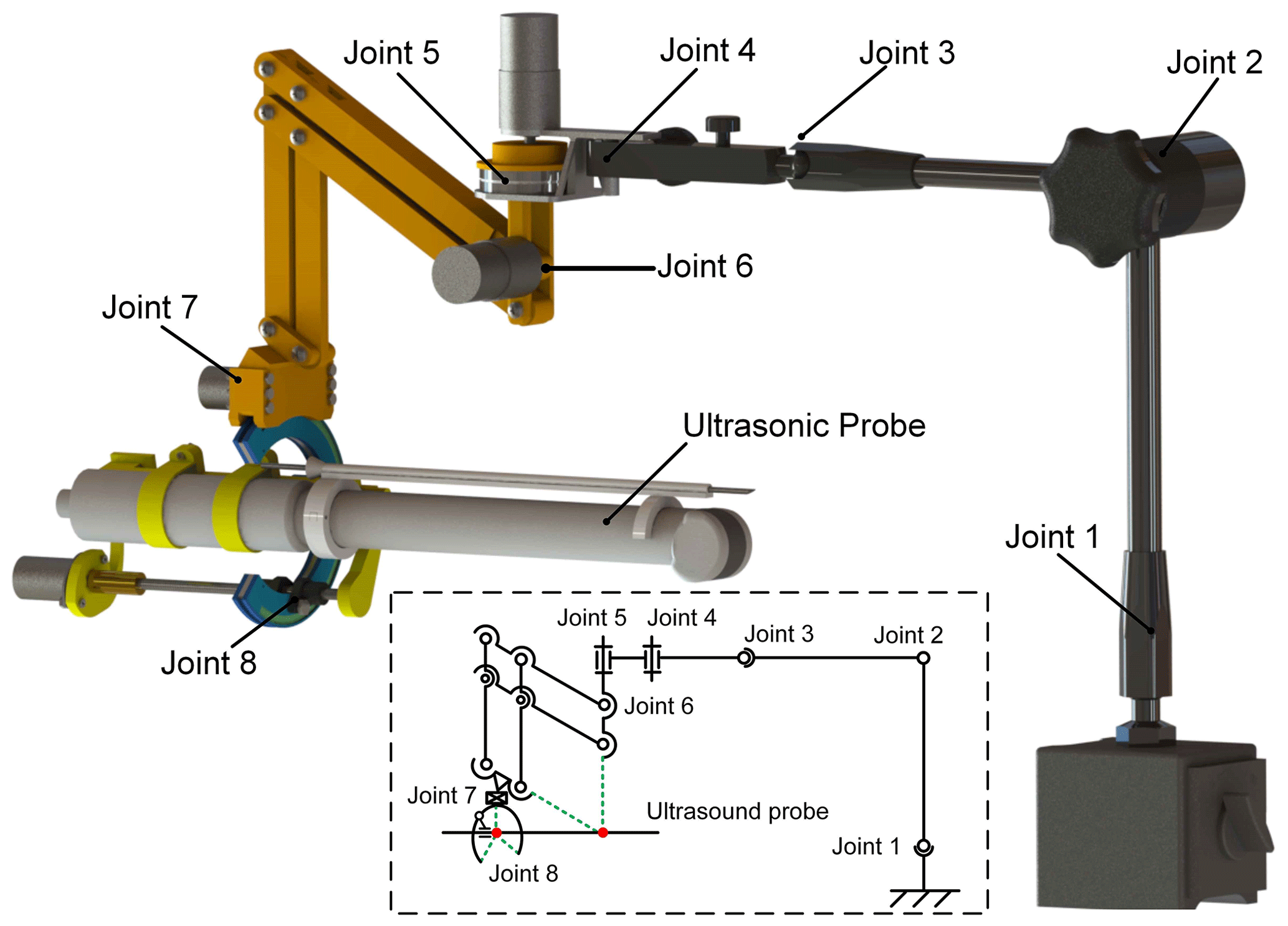
The transrectal prostate BT robot is composed of a preoperative position adjustment module, a posture adjustment module, and an ultrasound probe with self-rotation and a feeding module. Figure 7 is the overall structure diagram. The mechanism has 11 DOF, among which joints 1 to 4 are position adjustment modules with 7 DOF, and joints 5 to 8 are attitude adjustment modules with 4 DOF. The 7 DOF preoperative position adjustment module adopts the 7 DOF passive arm (MG61003) produced by Noga Engineering & Technology Ltd., Israel. The passive arm with 7 DOF can fix all the joints through a locking button.
In Sect. 2, the posture adjustment module and the self-rotation and feeding module of the ultrasound probe are designed. To verify if the ultrasound probe can scan various parts of the prostate at multiple angles in all directions, forward kinematic analysis of the two mechanisms is required to obtain its theoretical movement space and theoretical centering effect.
3.1 Kinematic analysis of the posture adjustment module and the self-rotation and feeding module
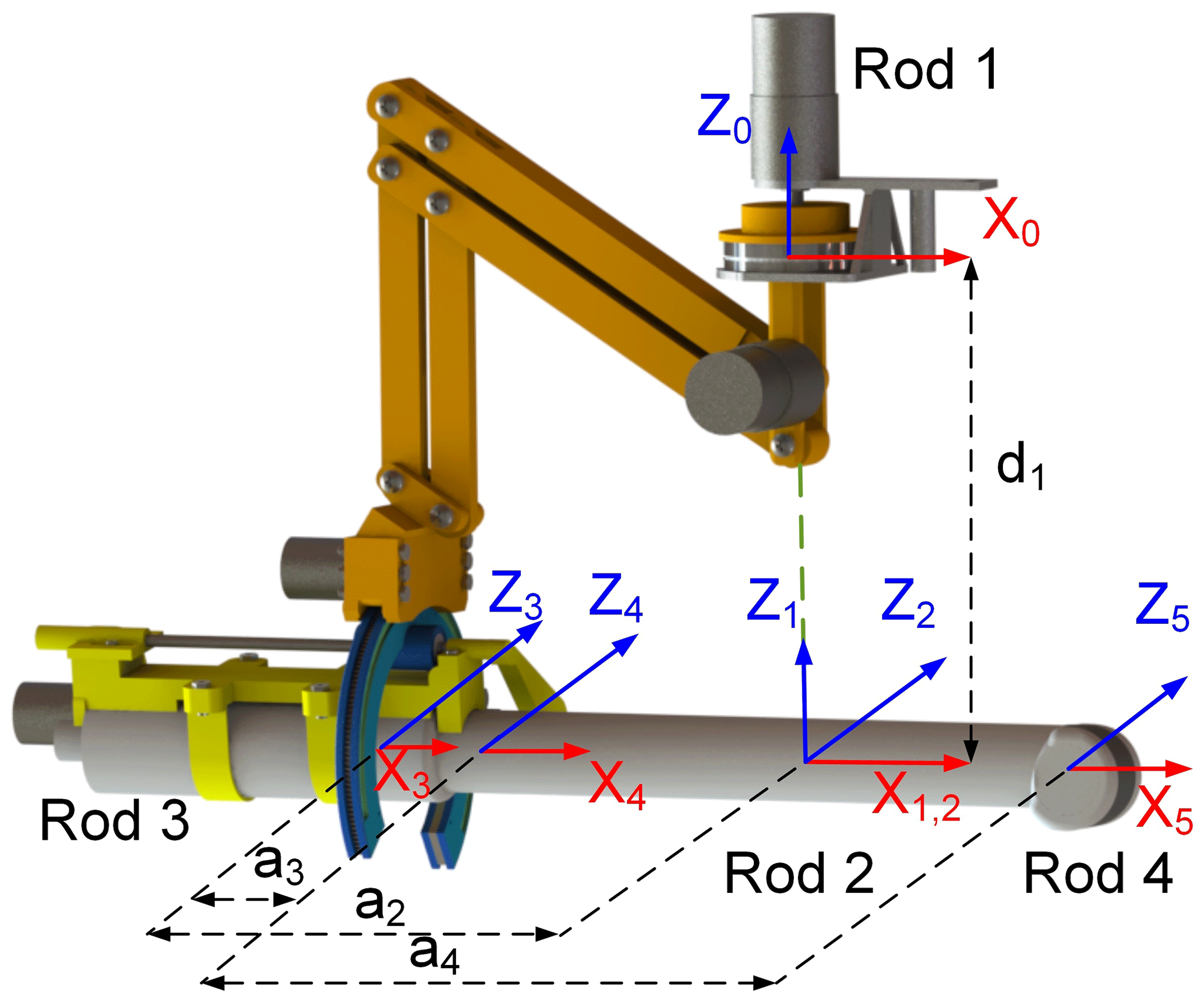
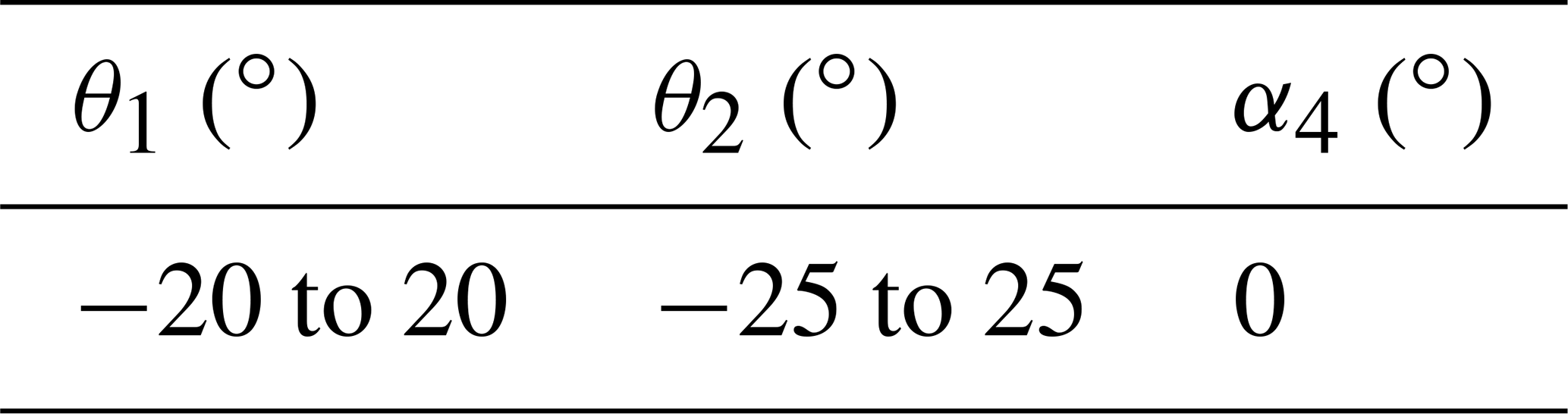
According to the ultrasound probe's posture adjustment module and the self-rotation and feeding module of the ultrasound probe mentioned in Sect. 2, based on the modified D–H (Denavit–Hartenberg) method, each connecting rod coordinate system of the two modules is established, as illustrated in Fig. 8. θ1 and θ2 are the azimuth and pitch angles of the RCM mechanism, a2 and a4 are the rod lengths of each rod, a3 is the feed distance of the ultrasound probe along the x4 axis, and α4 is the rotation angle of the ultrasound probe. The D–H parameters of each rod for both modules are presented in Table 1. Since the posture adjustment module is not a simple open-loop motion chain and is a six-rod mechanism composed of two parallel quadrangles, of which rod 1 is the rotating platform in the posture adjustment module, rods 2 and 3 are the probe's self-rotation and feed module installation platform and feed platform, respectively, and rod 4 is the ultrasound probe. Based on the analysis of the mechanism characteristics, the origin, O2, of the coordinate system of rod 2 is established at the remote center point. The origin, O3, of the coordinate system of rod 3 is established at the end of the feeding platform. The origin, O4, of the coordinate system of rod 4 is established at the end of the ultrasound probe, and the directions of the x2 and x3 axes are along the axis x4 of the ultrasound probe. Therefore, the system is regarded as a simple open-loop motion chain for discussion (Dong et al., 2016).

The kinematic equation T from the reference coordinate system of the base to the coordinate system at the end of the robot is expressed as follows:
The two modules' forward kinematic equation can be obtained by multiplying the five joints' homogeneous transformation matrix, as presented in Eq. (5).
In Eq. (5), R05 represents the posture and P05 represents the position, where, in the following:
In Eqs. (6), (7), (8), and (9), the following abbreviations represent the following trigonometric functions: s1 for sin θ1, c1 for cos θ1, sf1 for sin α1, cf1 for cos α1, and so on.
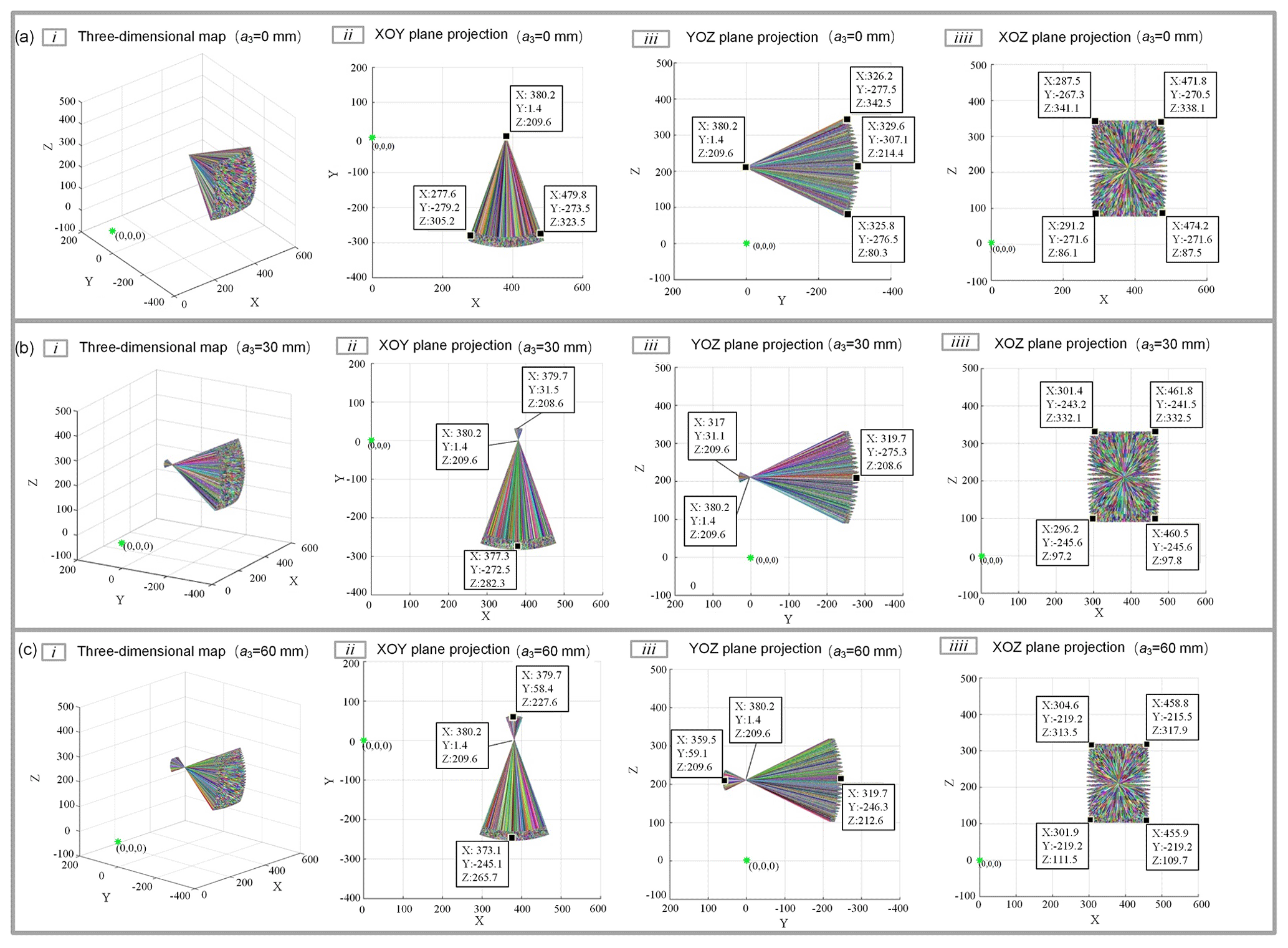
3.2 Simulation of the centering effect based on Simscape Multibody
According to the schematic diagram and connecting rod parameters plotted in Fig. 8 and Table 1, the posture adjustment module's physical model and the self-rotation and feeding module's physical models are established in MATLAB's Simscape Multibody toolbox, where the end trajectory of the ultrasound probe is tracked and recorded (Tatar et al., 2020; Turkkan and Su, 2016). The resulting position coordinate output will be recorded, and the working space graphic of the ultrasound probe will be drawn in the workspace. Table 2 presents the parameters of the two modules.
Figure 9a is the simulation result when a3=0 mm. The simulation result indicates that the remote center point coordinates are (362, 1.43, and 209.6). When the azimuth and pitch angle is set, the ultrasound probe is always located at the remote center point and can form a cone-shaped space with (380, 1.4, and 209.6) space position coordinates as the vertex to observe the centering effect after increasing a certain feed distance. Without changing the other joint parameters, the feed distance a3 of the ultrasound probe increases to 30 and 60 mm. The centering effect of the ultrasound probe with a feed of 30 and 60 mm is illustrated in Fig. 9b and c, respectively. After the measurement, the coordinates of this point are still the same (380, 1.4, and 209.6). The ultrasound probe realizes the change in the yaw angle and pitch angle, according to the center of the remote center point when a3=30 mm and a3=60 mm, which meets the design requirements.
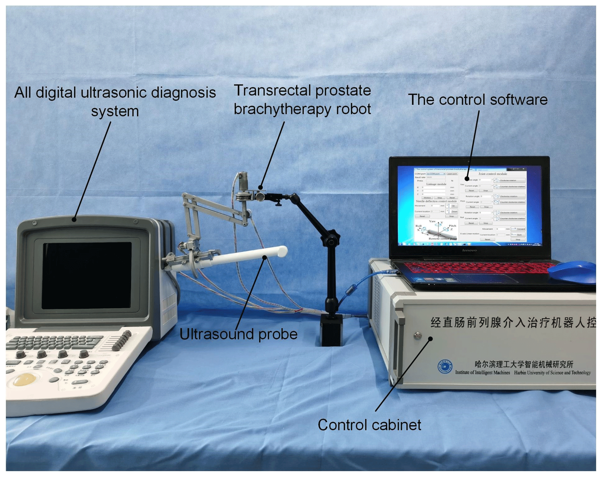
By simulating the actual surgical environment and the operation process, the reachable joint angle of the ultrasonic probe's posture adjustment mechanism is measured. The experiment of measuring the remote center point of the posture adjustment mechanism's error is conducted to verify whether the designed posture adjustment mechanism meets the actual surgical needs. The physical prototype of the transrectal BT robot is presented in Fig. 10.
4.1 Joint angle and corresponding motion error measurement
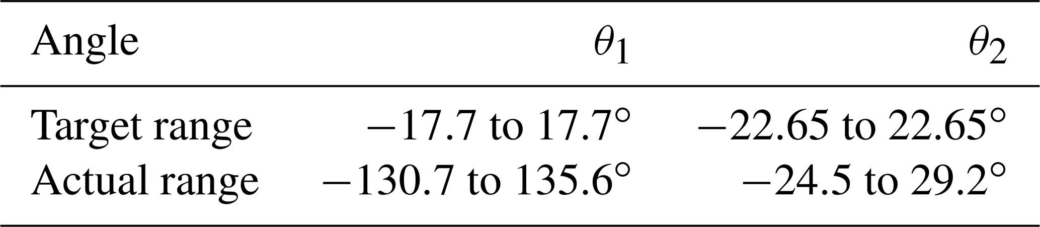
The robot's motion accuracy and motion range are factors that guarantee the BT effect; therefore, it is necessary to verify the joint rotation accuracy and motion range of the posture adjustment module. The electronic digital angle measuring instrument was used as the measuring instrument for this experiment (accuracy of 0.1∘). The rotation angle command is sent to the robot through the control software to measure the joint's actual rotation angle. The error of the joint (joints 5–7) angle rotation is controlled to within 1∘, as illustrated in Fig. 11. According to the design requirements of the posture adjustment module, the rotation range of the yaw angle of the set posture adjustment module is to 17.7∘, and the rotation range of the pitch angle is to 22.65∘. Therefore, the parameters of the above two joints were measured to verify whether they met the design requirements. Figure 12 presents the pitch angle's actual measurement results, and the measurement method of the yaw angle is the same. According to the joint angle parameters measured in Table 3, each joint can reach the ideal angle range and realize continuous rotation, while also meeting the actual clinical needs.
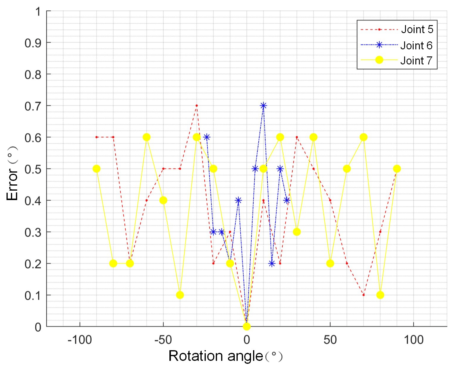

Table 2Attitude simulation parameters of the ultrasound probe at 0 and 30 mm feeding.
4.2 Error measurement and error analysis of the remote center point
In Sect. 3.2, the centering effect of the posture adjustment mechanism was verified from the simulation point of view; however, the centering effect of the actual physical prototype and the possible errors have not been considered. Therefore, it is necessary to assess the physical prototype's centering effect and then further analyze the measurement error to verify whether it meets the surgical requirements. Since this mechanism is used to realize the clamping, adjustment, and positioning functions of the ultrasound probe to assist the urologist in completing all-around scanning on the patient's prostate, it has higher safety performance requirements. The deformation of the whole mechanism under the action of gravity and external interference load will affect the position of the remote center point, while the offset of the remote center point will affect the positioning accuracy of the ultrasound probe during the actual surgery. When the ultrasound probe is performing yaw and pitch actions, the remote center point offsets the central point of the anus and thus makes the ultrasound probe unable to rotate around the central point of the anus, resulting in the anus being in contact with the ultrasound probe and receiving the pulling force of the ultrasound probe, which can cause harm to the patient. The motion error of the remote center point can be used as an essential index to evaluate the remote center's motion performance. Its measurement can realize the evaluation of the motion performance of the remote center of the posture adjustment mechanism. First of all, in the measurement space, it is hoped that the remote center point realizes the three-dimensional position change. Therefore, it is necessary to conduct two groups of experiments with the yaw angle (horizontal plane) remote center point motion error measurement and pitch angle (vertical plane) remote center point motion error measurement.
4.2.1 Measurement of the yaw angle's remote center point error
First, set the robot to a certain position, adjust the ultrasound probe's pitch angle to 0∘, and set the ultrasound probe's rotation angle α4 to = 0∘. Place the ultrasound probe in the area directly above the graph paper (scale 1 mm), as presented in Fig. 13. Fix the remote center point pointer onto the ultrasound probe's remote center point and record the remote center pointer's initial position. For different feeds a3 (0, 30, and 60 mm), adjust the yaw angle to −40, −20, 0, 20, and 40∘. The position coordinate data of the remote center point obtained by multiple measurements are summarized in Fig. 14. Under the same conditions, each group of experiments was conducted five times, and their mean value was taken as the final result. The measured distance between the remote center point and the space fixed point (2.4 and 2.1) is less than 1 mm, and the deformation of the anus is approximately 6 mm. Therefore, the measurement results indicate that the deviation distance can be within the range of the anus, which is in line with the surgical clinical requirements.
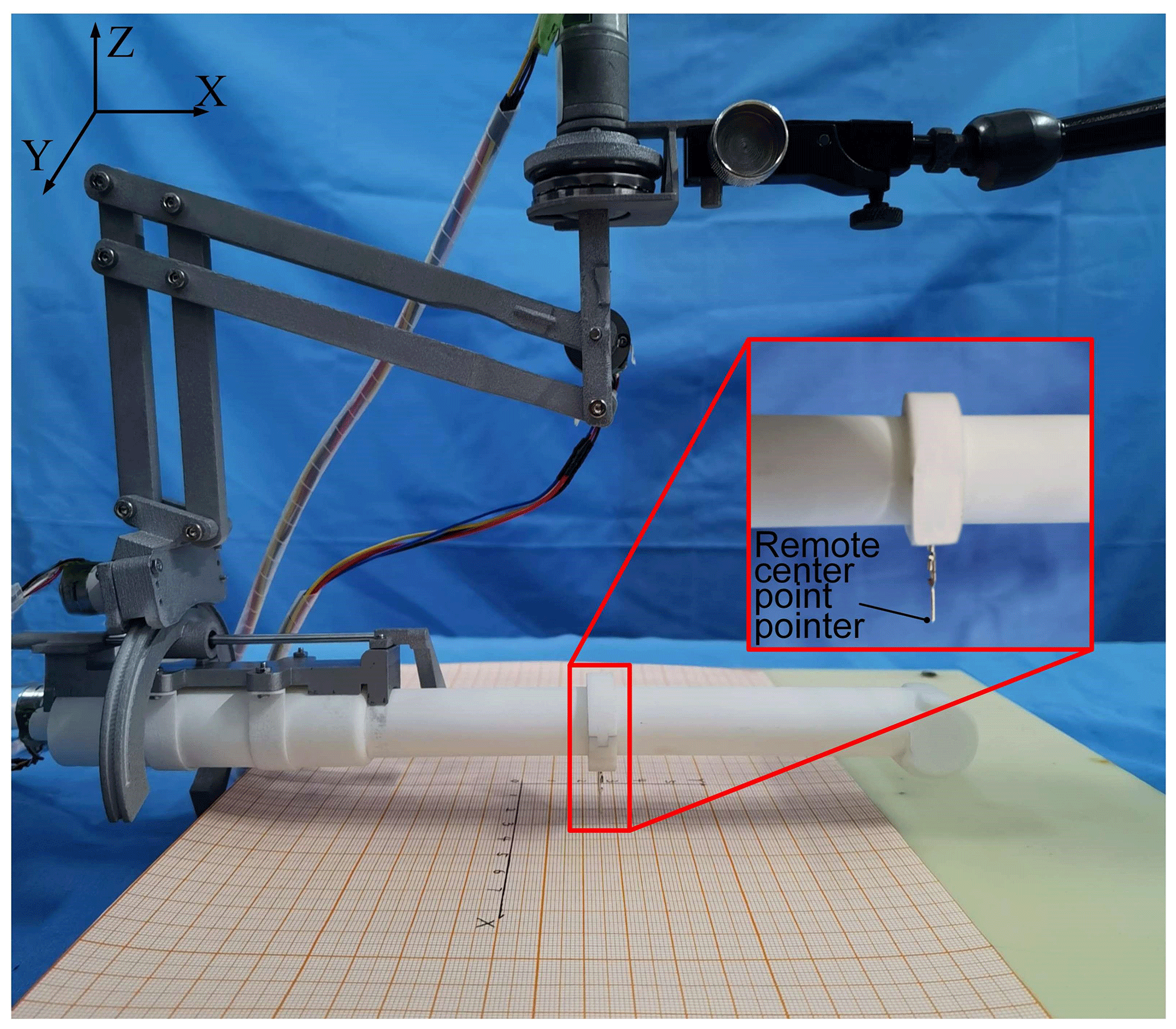
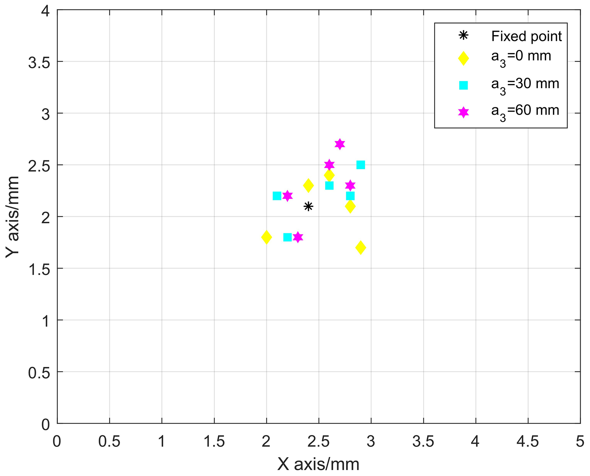
Figure 14The error measurement data distribution diagram of the yaw angle's remote center point.
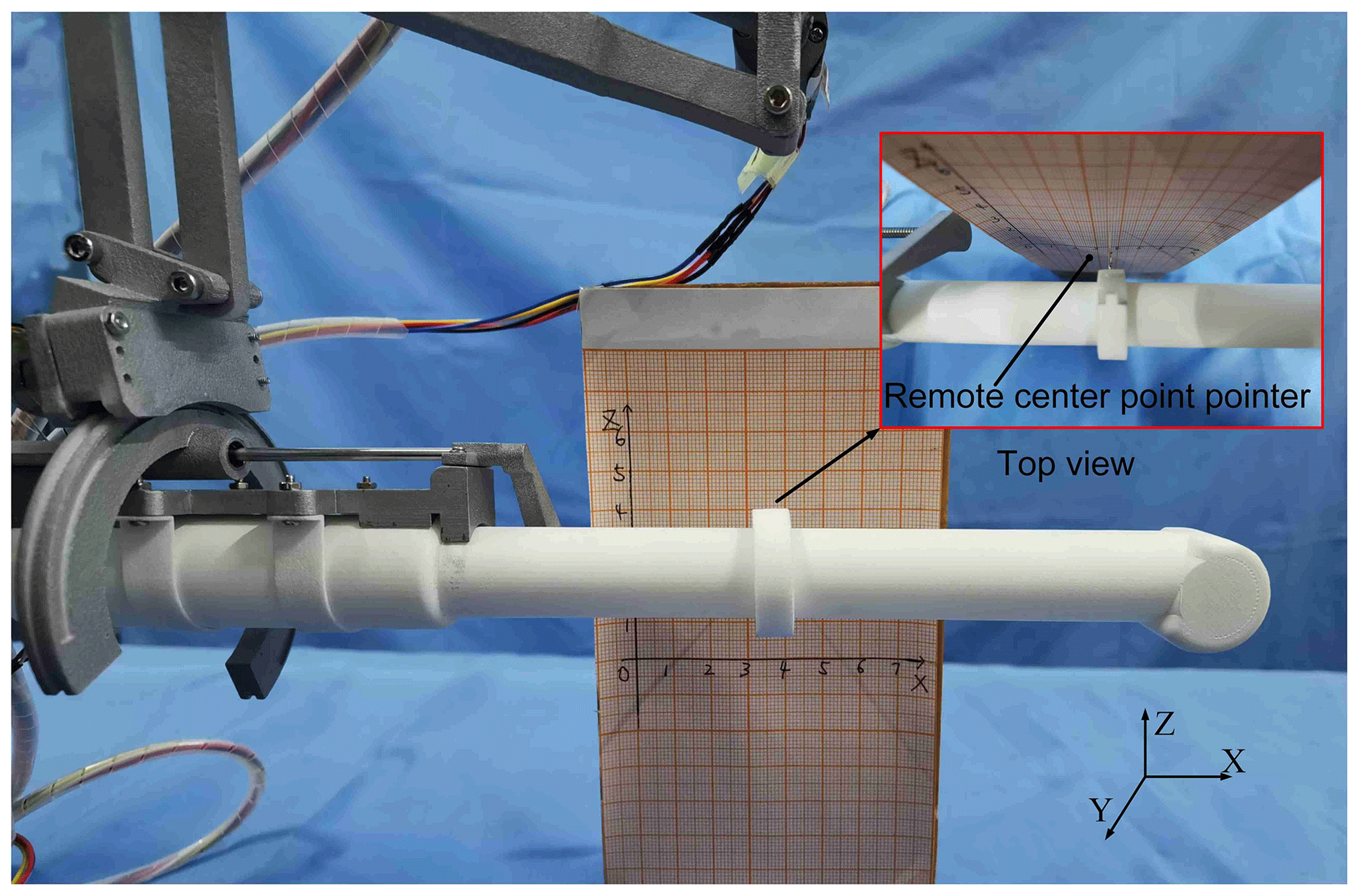

Figure 16The error measurement data distribution diagram of the pitch angle's remote center point.
4.2.2 Measurement of the pitch angle's remote center point error
Place the ultrasound probe in the area directly in front of the graph paper (scale 1 mm), as presented in Fig. 15. Fix the remote center pointer onto the ultrasound probe's remote center point and record the remote center point pointer's initial position. For different feeds a3 (0, 30, and 60 mm), adjust the pitch angle to −24, −12, 0, 12, and 24∘. Summarize the pitch angle's remote center point from multiple sets of measurements, as illustrated in Fig. 16. Under the same conditions, each group of experiments was conducted five times, and their mean value was taken as the final result. The distance between the measured remote center point and the space fixed point (3.6, 2) is less than 1 mm. The measurement results indicate that the deviation distance can also be within the scope of the anus, so it meets the requirements of clinical surgery.
4.2.3 Error analysis of the remote center point
Remote center point positioning errors include systematic errors and random errors, where the systematic error consists of multiple error factors with a deterministic change rule (Ernandes-Neto et al., 2020). Therefore, when considering the systematic error, the true values of the measurement mean and variance were used, and the confidence interval to define the systematic error limit was used. We define the safety factor and use as the μ's confidence interval, where μ is the mean of the measurement, s is the measurement variance, and is the unbiased estimator of μ. In order to determine the relative error, the relative fixed-point error and relative standard error are used as the evaluation indicators in each direction. The relative fixed-point error ε0 is the error of the measured mean value relative to the fixed point, and its expression is as follows:
where , x0 is the coordinate value of the fixed point. The relative standard deviation (RSD) can be used to test the precision of measurement results, and its expression is as follows:
While most random errors obey a normal distribution, their values range from −1 to 1 in order to reflect the random process in different spatial position relationships.
We then set two sets of random two-dimensional variables, with the random error in the x and y directions of the yaw angle measurement and the random error in the x and z directions of the pitch angle measurement. The correlation coefficient between the two-dimensional variables is defined as follows:
The abovementioned error analysis theory takes the 95 % confidence interval and calculates the measurement mean, relative fixed-point error, relative standard error, confidence interval, and relative parameters of the two-dimensional variables. The calculation results of azimuth error are presented in Table 4.
Table 4The error analysis result of the yaw angle's remote center point.
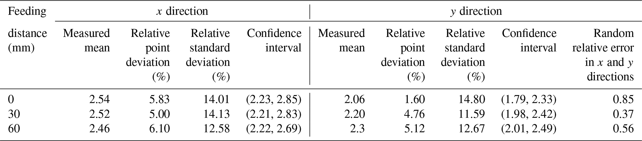
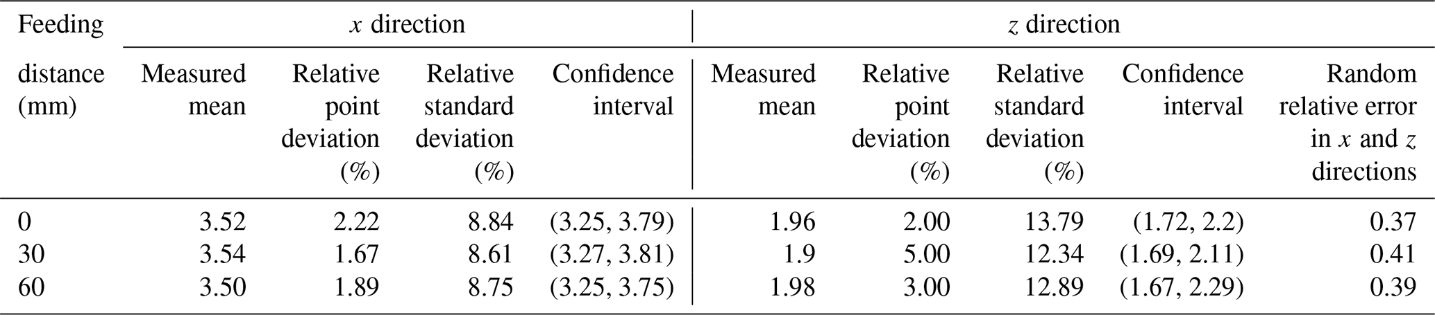
It can be seen from Table 4 that, at the same probe feed distance, the width of the confidence interval in the x direction is close to that of the y direction, which is stable at approximately 0.6 mm, indicating that the positioning performance is relatively stable. The relative fixed-point error and relative standard error in different feed directions remained stable in the x and y directions, both remained stable below 15 %, and the error could be controlled within 1 mm. The random relative error of x and y directions under different feeding distances is low, indicating that the correlation between the two parameters is not strong, and it proves that the measurement value of the y direction cannot be determined by measuring the x direction. The results indicate that the centering performance of the azimuth is stable, and the accuracy meets the requirements. In the same way, the error analysis is performed on the measurement data of the pitch angle's remote center point, and the analysis results are presented in Table 5. It can be seen from Table 5 that, when the feeding distance of the probe is kept, the width of the confidence interval in the x and z directions is close and stable at approximately 0.5 mm, ensuring the stability of the centering performance. When the probe feed distance is varied, the relative fixed-point error can be controlled within 1 mm. The relative standard error of each group fluctuates less, indicating that the accuracy of the measurement experiment is reliable. Similarly, the values of random relative errors in the x and z directions are also relatively small, demonstrating that the two variables are not strongly correlated. The results indicate that the centering performance of the pitch angle is also stable and accurate enough to meet the requirements of clinical surgery.
Table 5The error analysis result of the pitch angle's remote center point.
In this paper, we propose a robot for transrectal prostate BT. The robot can assist urologists in operating the ultrasonic probe. While reducing the labor intensity of the urologist, compared with the urologist's manual operation of the ultrasonic probe, the posture adjustment accuracy of the ultrasound probe can also be improved. The transrectal prostate BT robot is composed of a position adjustment module, a posture adjustment module, and an ultrasound probe with self-rotation and a feeding module. Among them, the posture adjustment module selects the RCM mechanism with double parallelograms, thus allowing the ultrasound probe to make a centering movement at the peripheral center point of the patient's anus. To verify the centering effect of the ultrasound probe, we set the coordinates of the remote center point and selected two different feed distances to simulate the centering point of the ultrasound probe, based on Simscape Multibody. The simulation results indicated that the ultrasound probe achieves a very stable centering effect under different feeds, and it was verified from the perspective of the simulation that the mechanism can meet the requirements of actual clinical surgery. Finally, a physical prototype of the transrectal prostate BT robot was developed. We assessed the robot's joint motion, the error of the joint angle rotation was controlled to within 1∘, and the joint rotation range could meet the scanning area of the ultrasound probe covering the entire prostate. Then the posture adjustment module's remote center point motion errors of the azimuth and pitch angles were measured. The error analysis of the measured data indicated that the ultrasound probe's centering performance was stable when adjusting the attitude at different feeds. The accuracy can meet the surgical requirements.
All data included in this study are available upon request from the corresponding author.
YZ proposed and developed the overall concept of the paper. XD conducted the mechanism design and simulations and wrote the majority of the paper. JJ supervised and structured the paper. BL and SZ helped to make the figures.
The contact author has declared that neither they nor their co-authors have any competing interests.
Publisher's note: Copernicus Publications remains neutral with regard to jurisdictional claims in published maps and institutional affiliations.
The authors thank TopEdit (https://www.topeditsci.com, last access: 20 February 2022) for its linguistic assistance during the preparation of this paper.
This research has been supported by the Reserve Leader Funding Project of Leading Talent Echelon of Heilongjiang Province of China (grant no. 2501050628) and by the Science and Technology Innovation Team Project of Foshan City of China (grant no. 2018IT100302).
This paper was edited by Guowu Wei and reviewed by two anonymous referees.
Alberto, M., Ugo, G. F., Arnauld, V., Paolo, D. O., Elio, M., Riccaedo, A., Marcio, C. M., Maurizio, B., Carlo, A. B., Alberto, B., Guilherme, S., Jihad, H., Mani, M., Silvia, S., Aldo, M. B., Gongxian, W., Xiaochen, Z., Francesco, P., Alexandre, M., Vipul, P., Vipul, P., Ashutosh, K. T., Frncesco, M., Richard, G., Wiklund, N. P., and Ashok, K. H.: Contemporary Techniques of Prostate Dissection for Robot-assisted Prostatectomy, Eur. Urol., 78, 583–591, https://doi.org/10.1016/j.eururo.2020.07.017, 2020.
Chen, S., Gonenc, B., Li, M., Song, D. Y., Burdette, E. C., Iordachita, I., and Kazanzides, P.: Needle release mechanism enabling multiple insertions with an ultrasound-guided prostate brachytherapy robot, 2017 39th Annual International Conference of the IEEE Engineering in Medicine and Biology Society (EMBC), Seogwipo, South Korea, 4339–4342, 2017.
Corkum, M. T., Morton, G., Louie, A. V., Bauman, G. S., Mendez, L. C., Chin, J., D'Souza, D. P., Dinniwell, R. E., Velker, V. M., and Saskin, R.: Is prostate brachytherapy a dying art? Trends and variation in the definitive management of prostate cancer in Ontario, Canada, Radiother. Oncol., 152, 42–48, https://doi.org/10.1016/j.radonc.2020.07.036, 2020.
Culp, M. B., Soerjomataram, I., Efstathiou, J. A., Bray, F., and Jemal, A.: Recent global patterns in prostate cancer incidence and mortality rates, Eur. Urol., 77, 38–52, https://doi.org/10.1016/j.eururo.2019.08.005, 2020.
Dai, X. S., Zhang, Y. D., Jiang, J. G., and Li, B.: Image-guided robots for low dose rate (LDR) prostate brachytherapy: perspectives on safety in design and use, Int. J. Med. Robot. Comp., 17, e2239, https://doi.org/10.1002/rcs.2239, 2021.
Djohossou, M.: Robot parallèle comanipulé pour l'assistance en curiethérapie de la prostate, 2019, doctoral thesis, Université de Bretagne occidentale-Brest, 2019.
Dong, W., Lin, W., Qian, C., Ye, C., and Gao, H.: GA-based modified D-H method calibration modelling for 6-DOFs serial robot, Chinese Association of Automation IEEE, 11–13 November 2016, Wuhan, China, 2016.
Ernandes-Neto, V., Pacheco, G. V., and Brando, A. S.: On the Weighting of Control Signals in a Multi-robot System: A Formation-Based Analysis, Journal of Control, Automation and Electrical Systems, 31, 1121–1131, https://doi.org/10.1007/s40313-020-00615-7, 2020.
Feng, Y. Q., Wang, Y. Q., Xu, D. Y., and Zhang, Y. F.: Study on prostate volume of 957 volunteers by using trans-abdominal ultrasound and analysis of correlative factors with the prostate size, Chinese Journal of Andrilogy, 7, 33–35, https://doi.org/10.3969/j.issn.1008-0848.2009.07.009, 2009.
Fichtinger, G., Burdette, E. C., Tanacs, A., Patriciu, A., Mazilu, D., Whitcomb, L. L., and Stoianovici, D.: Robotically assisted prostate brachytherapy with transrectal ultrasound guidance – Phantom experiments, Brachytherapy, 5, 14–26, https://doi.org/10.1016/j.brachy.2005.10.003, 2006.
Fichtinger, G., Fiene, J. P., Kennedy, C. W., Kronreif, G., Iordachita, I., Song, D. Y., Burdette, E. C., and Kazanzides, P.: Robotic assistance for ultrasound-guided prostate brachytherapy, Med. Image Anal., 12, 535–545, https://doi.org/10.1016/j.media.2008.06.002, 2008.
Halima, A. B., Bert, J., Clément, J. F., and Visvikis, D.: Development of a 6 Degrees of Freedom Prostate Brachytherapy Robot with Integrated Gravity Compensation System, International Symposium on Medical Robotics (ISMR), 17–19 November 2021, Atlanta, USA, 2021.
Lagerburg, V., Moerland, M. A., van Vulpen, M., and Lagendijk, J. J.: A new robotic needle insertion method to minimise attendant prostate motion, Radiother. Oncol., 80, 73–77, https://doi.org/10.1016/j.radonc.2006.06.013, 2006.
Nguyen Phu, S., Essomba, T., Idram, I., and Lai, J.-Y.: Kinematic analysis and evaluation of a hybrid mechanism for computer assisted bone reduction surgery, Mech. Sci., 10, 589–604, https://doi.org/10.5194/ms-10-589-2019, 2019.
Rivard, M. J., Evans, D. A. R., and Kay, I.: A technical evaluation of the Nucletron FIRST system: Conformance of a remote afterloading brachytherapy seed implantation system to manufacturer specifications and AAPM Task Group report recommendations, J. Appl. Clin. Med. Phys., 6, 22–50, https://doi.org/10.1120/jacmp.v6i1.1985, 2005.
Tatar, A. B., Tanyldz, A. K., and Yakut, O.: Four-legged hunter (FLH) robot: design and shooting control to moving targets with SMC, Simul. Model. Pract. Th., 104, 102117, https://doi.org/10.1016/j.simpat.2020.102117, 2020.
Turkkan, O. A. and Su, H.-J.: DAS-2D: a concept design tool for compliant mechanisms, Mech. Sci., 7, 135–148, https://doi.org/10.5194/ms-7-135-2016, 2016.
Vaggers, S., Rai, B. P., Chedgy, E. C. P., Taille, A. D. L., and Somani, B. K.: Polyethylene glycol-based hydrogel rectal spacers for prostate brachytherapy: a systematic review with a focus on technique, World J. Urol., 39, 1769–1780, https://doi.org/10.1007/s00345-020-03414-6, 2020.
Wei, Z., Downey, D., and Fenster, A.: MO-E-T-618-03: Dynamic Intraoperative Prostate Brachytherapy Using 3D TRUS Guidance with Robotic Assistance, Med. Phys., 32, 2069–2069, https://doi.org/10.1118/1.1998300, 2005.
Xin, Y. P., Guo, D. N., Shao, H. G., Qi, J. G., Zhou, X. P., Chen, Z. G., and Yuan, G. Y.: Clinical Study of 125 I Particle Implantation in Treatment of Patients with Prostate Cancer, Medical & Pharmaceutical Journal of Chinese People's Liberation Army, 30, 45–48, https://doi.org/10.3969/j.issn.2095-140X.2018.11.010, 2018.
Yongde, Z., Yi, L., Xiaofei, W., and Yong, X.: Design and experimental study of joint torque balance mechanism of seed implantation articulated robot, Adv. Mech. Eng., 7, 1687814015589479, https://doi.org/10.1177/1687814015589479, 2015.
Yu, Y., Podder, T., Zhang, Y., Ng, W., Misic, V., Sherman, J., Fuller, D., Rubens, D., Strang, J., and Brasacchio, R.: Robotic system for prostate brachytherapy, Comput. Aided Surg., 12, 366–370, https://doi.org/10.3109/10929080701746926, 2007.
Zhang, S., Jiang, S., Yang, Z., and Liu, R.: 2D ultrasound and 3D MR image registration of the prostate for brachytherapy surgical navigation, Medicine, 94, e1643, https://doi.org/10.1097/MD.0000000000001643, 2015.