the Creative Commons Attribution 4.0 License.
the Creative Commons Attribution 4.0 License.
 | 12 Apr 2022
A chord-angle-based approach with expandable solution space to 1-degree-of-freedom (DOF) rehabilitation mechanism synthesis
Wei Wei
Xin Shu
Peng Chen
Xiangyun Li
Rehabilitation robots have been proven to be an effective tool for patient motor recovery in clinical medicine. Recently, few degrees of freedom (DOFs), especially 1-DOF, rehabilitation robots have drawn increasing attention as the complexity and cost of the control system would be significantly reduced. In this paper, the mechanism synthesis problem of 1-DOF rehabilitation robots is studied. Traditional synthesis methods usually aim at minimizing the trajectory error to generate a mathematically optimal solution, which may not be a practically feasible solution in terms of engineering constraints. Therefore, we propose a novel mechanism synthesis approach based on chord angle descriptor (CAD) and error tolerance expansion to generate a pool of mechanism solutions from which mathematically and practically optimal solutions can be selected. CAD is utilized for its capability to represent the same-shaped trajectories of different mechanisms in a unified way, and it is robust to the noise in the rehabilitation trajectory acquired by motion capture systems. Then a library of mechanism trajectories is established with compressed representations of CAD via an auto-encoder algorithm to speed up the matching between mechanism and rehabilitation trajectory where the matching error tolerance can be adjusted according to practical rehabilitation specifications. Finally, a design example of a 1-DOF rehabilitation robot for upper-limb training is provided to demonstrate the efficacy of our novel approach.
- Article
(3926 KB) - Full-text XML
- BibTeX
- EndNote


There is an increasing number of people who are suffering from sensorimotor disabilities due to the large aging population. Stroke, particularly, is a leading cause of disability worldwide (Defebvre and Krystkowiak, 2016). Scientific research and clinical experiments have shown that rehabilitation training can reduce the disabilities and improve motor function, allowing patients to regain much of their independence and quality of life (Narayan Arya et al., 2012; Caproni and Colosimo, 2017). In the traditional rehabilitation training process, the affected limbs of the patients are guided by the therapist to perform predefined movement patterns repetitively. This process is slow and labor-intensive, usually involving extensive interaction between multiple therapists and one patient. With the development of automation technology, robot-aided rehabilitation has become a useful tool to restore and reinforce motor functions for patients. A rehabilitation robot can provide patients with intensive and reproducible movement training in time-unlimited durations, which not only alleviates stress for therapists but also provides quantitative diagnosis and assessments of motor impairments (Aprile et al., 2020; Rodrigues et al., 2021; Bertani et al., 2017; Kan et al., 2011).
Most rehabilitation robots use multi-DOF (degree of freedom) mechanisms to adapt to different users. Kemna et al. (2009) developed an end traction mechanism robot called iPAM, which uses two 3-DOF mechanisms to pull the forearm and upper arm, respectively, to complete shoulder–elbow coordination exercises (Kemna et al., 2009). Rosati et al. (2007) designed a 3-DOF upper-limb training mechanism powered by ropes to achieve upper-limb rehabilitation while compensating for arm weight (Rosati et al., 2007). Li et al. (2006) developed a 5-DOF wearable upper-limb rehabilitation training mechanism, which is controlled based on surface electromyography signals and can assist hemiplegic patients to carry out individual and cooperative exercise training of the shoulder, elbow, and wrist (Li et al., 2006). While these multi-DOF mechanisms can help patients perform various kinds of rehabilitation movements owing to redundant workspace, their motion dynamics are realized by the underlying control system composed of multiple actuators, sensors, and complex control algorithms, which greatly increases the purchase and maintenance cost. Moreover, the possible malfunction of the control system may result in secondary injuries to patients where the rehabilitation mechanism moves the patient's joint out of its range of motion (ROM).
To avoid those problems of multi-DOF mechanisms, 1-DOF rehabilitation mechanisms have been investigated in recent years. Zhao et al. (2021) designed a 1-DOF mechanism to guide patients' upper limbs through target points and developed a set of virtual reality (VR)-based rehabilitation systems using Unity3D software, which can provide users with an immersive experience and provide management personnel with rehabilitation movement data (Zhao et al., 2021). Theriault et al. (2014) developed a 1-DOF haptic robot for post-stroke arm rehabilitation for in-home and clinical use. The robot can apply proper assistive force when interacting with the patient, thereby extending the functionality of the system to accommodate low-functioning patients (Theriault et al., 2014). Zhu et al. (2020) proposed a 1-DOF rehabilitation robot based on the coupled-serial-chain mechanism to assist the sit-to-stand movement of patients with lower-limb disabilities (Zhu et al., 2020). Those robots are affordable and simple to operate thanks to a single actuator, and their workspace is limited and must be adapted to the workspace of a particular rehabilitation task, usually the trajectory of a specific joint. To design a 1-DOF mechanism to generate the matching trajectory, motion capture systems are used to obtain the task trajectory as the input to the subsequent mechanism synthesis algorithm, which has been demonstrated in our recent paper (Zhao et al., 2021).
When patients of different body dimensions perform the same rehabilitation movement task, the trajectories of their joints may vary in position, orientation, and scale, except for shape; in terms of mechanism synthesis, curves of different position, orientation, and scale but identical shape will result in mechanisms with identical relative dimensions, i.e., identical link length ratios. Therefore, shape extraction is an essential step for rehabilitation mechanism synthesis towards a particular movement task. In the literature of mechanism synthesis, numerous types of curve descriptors have been proposed such as Fourier descriptor (FD) (Zhang and Lu, 2002) and Haar wavelet descriptor (HWD) (Nabout and Tibken, 2008). However, these shape descriptors are subject to similar transformation (translation, rotation, and scaling) and susceptible to bias by the necessity of matching coordinates. Hence, shape-error-based descriptors are needed to evaluate the underlying differences in shape. On the other hand, there exists a few types of descriptors specifically measuring shape differences, like curvature descriptor (CD) (Deshpande and Purwar, 2019) and turning function descriptor (TFD) (Torres-Moreno et al., 2022), but they are highly sensitive to noise embedded in motion capture systems (Holden, 2018). As a result, a noise-robust and shape-error-based descriptor is required to facilitate the synthesis of a 1-DOF mechanism for rehabilitation purposes.
Upon obtaining the shape signature of the target trajectory, mechanism synthesis algorithms are applied to determine the optimal linkage parameters. Conventional approaches usually focus on finding an optimal solution, which is closest to the prescribed curve mathematically. However, such a solution may become infeasible from an engineering point of view. For example, such a solution may contain overlong links or fixed pivots outside of the required region. In this paper, an alternative way, following our previous work on motion synthesis (Zhao et al., 2016), is presented by outputting a pool of candidate mechanisms via adjusting the fitting error tolerance, from which both mathematically and practically optimal solutions can be obtained. The clinical motivation for tolerance adjustment is based on human movement variability (Sutter et al., 2021) – no movement can be exactly repeated due to inevitable noise in the nervous system (Faisal et al., 2008; Harris and Wolpert, 1998). Therefore, in the context of rehabilitation mechanism synthesis, this effect allows the approximation of the target rehabilitation trajectory by similar mechanism curves within a reasonable tolerance.
To this end, we present a path synthesis approach specifically towards a 1-DOF rehabilitation mechanism with expandable solution space whose extent is bounded by the degree of human movement variability and using a shape-difference-based descriptor called chord angle descriptor to handle the trajectory of a particular rehabilitation task without being affected by translation, rotation, or scale changes. In addition, a trajectory library with different kinds of mechanisms is established and an auto-encoder algorithm from the field of machine learning is adopted to adjust the error tolerance for expanding solutions. The rest of this paper is as follows. Sect. 2 gives the definition of chord angle descriptor. In Sect. 3, a mechanism curve library with compressed CAD is constructed to facilitate the comparison between approximate and target curves. Section 4 illustrates the CAD-based matching algorithm for mechanism and rehabilitation paths. Then, an example of circle-tracing trajectory generation for upper-limb rehabilitation is presented in Sect. 5 to demonstrate the validity of the proposed method. Finally, Sect. 6 contains the conclusions and future work.
When different patients are performing the same rehabilitation task, trajectories vary in size and direction but not shape. Although many descriptors can be used to represent the shape features (Cao et al., 2011; Adamek and Connor, 2004; Alajlan et al., 2007; Mokhtarian et al., 1998; Zhang and Lu, 2002), some descriptors such as CD and TFD are sensitive to noise and need to smooth the trajectory beforehand. In other cases, some descriptors such as FD and HWD are variant to similar transformation, which leads to the time-consuming normalization of the trajectory. In this paper, we introduce the chord angle descriptor to extract the shape features of the trajectory for mechanism synthesis. This descriptor is independent of position, orientation, and size, and it has a certain anti-interference ability, which will be described later.
2.1 Definition of chord angle descriptor
The chord angle descriptor is a descriptor based on the string angles between the curve sampling points. Figure 1 shows a planar trajectory with n equal-interval contour points, namely, , where indicates the two-dimensional (2D) plane coordinates. Here, we use the chord angle θij to describe its shape characteristics based on the spatial position relation between the contour sampling points.
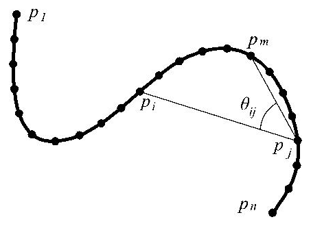
For any two points pi and pj on the contour, θij is defined as the chord angle between the chord vector pipj and the chord vector pjpm . The point pm must always be different from pi and pj to ensure that pi, pj, and pm can form a triangle. To achieve this, we can define point pm as
where Δ is a parameter that is used to distinguish pm from pj. For a trajectory which has n sampling points, . From the definition of pm in Eq. (1), it is obvious that in the case of i>j, must be satisfied. So . Similarly, in the case of i≤j, is needed, so . For the convenience of calculation for both cases, pm can be chosen between pi and pj, which actually means a small positive integer can be selected for Δ to satisfy both conditions; for example, Δ=4.
Based on the definition of pm provided above, for any pi, pj that belongs to the set of P, we can construct the formula of the chord angle θij as
where θij is in the range of [0,π]. ∠(pipj,pjpm) is calculated by the following arccosine formula:
Next, to make the description of the path shape consistent with the sense of human vision, θij is transformed into logarithmic space by
For any point pi on the trajectory, the complete chord angle descriptor is []. By developing a chord angle descriptor for each sampling point on the path curve, we can obtain the n×n dimensional CAD matrix of the entire patch as
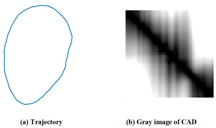
For example, a trajectory is shown in Fig. 2a, and its gray image of the CAD matrix is shown in Fig. 2b. The image can be obtained by the MATLAB imshow function. As is shown, the color of Fig. 2b on the diagonal is black since the value of θij on the diagonal is 0, and the color close to black signifies that θij in those areas is closed to 0. Conversely, the white color of the image means that θij equals π.
2.2 Characteristics of CAD
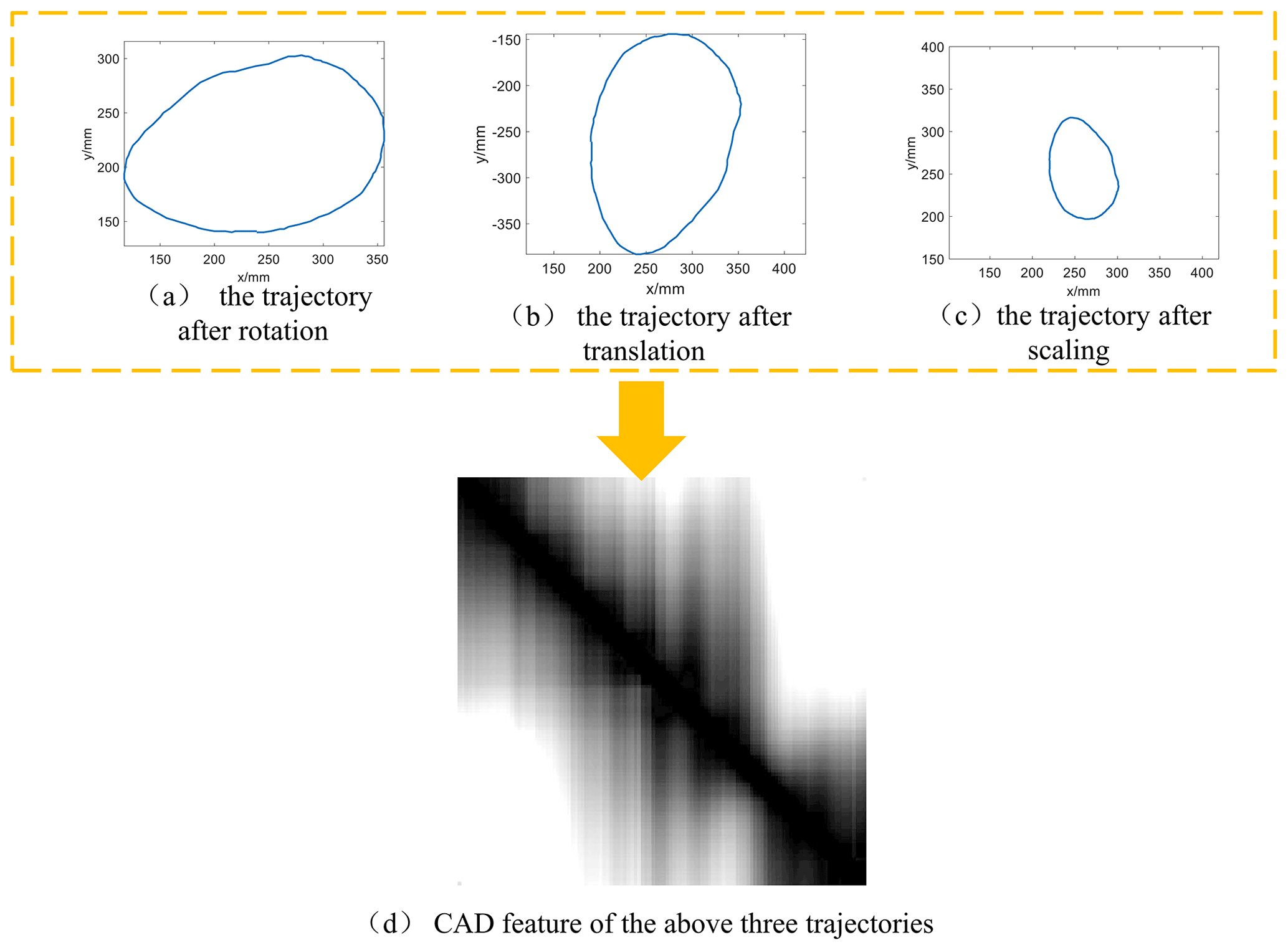
One advantage of using CAD to extract trajectory features is that CAD is independent of the frame position, the frame deflection angle, and the overall scaling ratio of the mechanism. For example, Fig. 3a–c show three different trajectories which are transformed from the original trajectory in Fig. 2a with rotation, translation, and scaling, respectively; since the chord angle is invariant with the similar transformation, the shape of these three trajectories remains the same, so they can be represented by one set of CAD in a unified way. This is beneficial to the design of the rehabilitation robot, which means that mechanism results will not contain the pseudo-multiple solutions with same link length ratio.
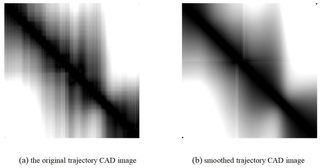
Another advantage of the CAD descriptor is that it is noise proof, i.e., resistant to noise. For illustration, Fig. 4 shows two trajectories, in which Fig. 4a is the original trajectory with noise signals, and Fig. 4b is the smoothed curve. Figures 5 and 6 show the shape features of these two curves extracted by curvature and CAD matrix, respectively.
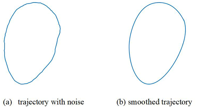
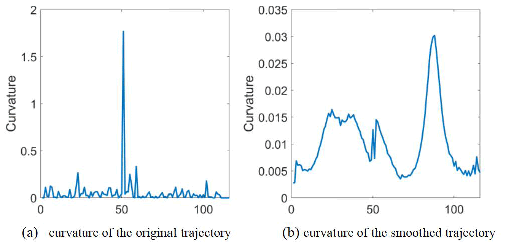
Figure 5Curvature descriptor of the two trajectories in Fig. 4. The horizontal axis represents the numbers of the sampling of the path, and the vertical axis represents the curvature.
As can be seen from Fig. 5, when the curvature is used as the shape descriptor, the interference signals “drown” the original curve, so it is difficult to identify the curvature of the smooth path from the curvature with the noise. Therefore, for the trajectory with noise signals, it is difficult to extract the shape features accurately by using the curvature descriptor.
When the CAD matrix is used as the descriptor of trajectory shape features, as shown in Fig. 6, the noise signal does not drown the CAD feature of the smooth trajectory, although the CAD image with noise signals has some extra vertical lines when compared with the CAD image of smooth trajectory. This means that the shape features of smooth trajectory can still be recognized from the shape features of the noise path. This advantage is particularly beneficial for acquiring the motion trajectory in designing rehabilitation robots. This is because, while utilizing sports equipment to collect the trajectory of rehabilitation training, the collected trajectory will unavoidably have some noise due to the limitation of equipment accuracy. However, these noise signals have little effect on CAD when compared with other trajectory descriptors.
When acquiring the trajectory of rehabilitation training, one way to get the corresponding mechanism is the library method, that is, finding the mechanism trajectory that is similar to the rehabilitation trajectory in the database and taking the linkage parameters of the mechanism as the initial values of the design parameter of the 1-DOF rehabilitation robot. This approach is suitable for computer-aided solutions due to its high precision, and it is immune to circuit and branch problems. To design a rehabilitation mechanism that generates movement trajectory, we build a library and combine it with our CAD trajectory feature to obtain a diverse set of conceptual design solutions.
3.1 Range of mechanism design parameters
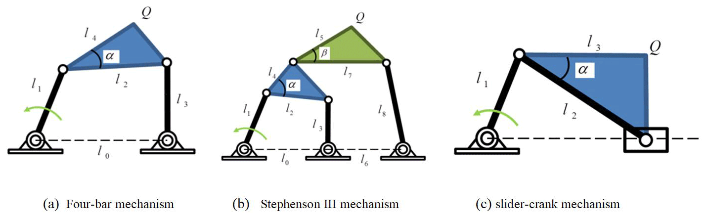
To design a mechanism with the library method, the first step is to establish a database containing the link parameters and the compressed CAD features of the trajectories of different mechanisms. When given a target movement trajectory, the target trajectory is compared with the trajectories in the database by CAD to find the mechanisms that match the target trajectory. The library in this paper includes three types of mechanisms: the four-bar mechanism, the Stephenson III mechanism, and the slider-crank mechanism, which are shown in Fig. 7. The coupler point Q in Fig. 7 is the generating point of the motion trajectory of the mechanism.
Due to the nonlinearity of these 1-DOF mechanisms, small changes in linkage parameters can produce large changes in the generated paths. Deshpande and Purwar (2019) has demonstrated that whenever the link ratios of four-bar linkage are close to one, the sensitivity of the shape of a coupler motion is higher than it would be otherwise (Deshpande and Purwar, 2019).
In order to generate diverse types of coupler trajectories, length parameters of the mechanisms in this paper are chosen according to the research results by Deshpande and Purwar (2019). To be specific, the length parameters of a mechanism in a library are stored in the form of proportional length, and the frame distance l0 is taken as the benchmark (l0=1). The ratio of the remaining link lengths to l0 satisfies the normal distribution relation: the l1 – l3 to l0 ratio satisfies the lognormal distribution (), and the l4−l8 to l0 ratio satisfies the normal distribution (). Twenty thousand groups of different linkage parameters are comprised in the library. The motion trajectory of the point Q is obtained by the kinematic method, and each trajectory has 50 sample points.
3.2 Auto-encoder for CAD of mechanism trajectory
After obtaining the trajectory of each mechanism in the library, the CAD feature of each trajectory is calculated from Eq. (5). If we directly store the CAD matrix of each mechanism trajectory, it will cause the problem of the “curse of dimensionality” (Marimont and Shapiro, 1979) due to the high dimensionality of the CAD matrix. Therefore, we borrow the auto-encoder algorithm (Ng, 2011) from the field of machine learning to reduce the dimensionality of CAD matrix. The auto-encoder is a neural network which attempts to replicate its input at its output and utilizes the compressed feature in the hidden layer or space to represent the input data, i.e., the CAD matrix, which is calculated by Eq. (5).
Figure 8 shows an auto-encoder neural network architecture similar to that which we used in this study. The entire neural network consists of three simple auto-encoders stacked on top of each other. As the dimension of the CAD is 50×50, the number of neurons in the input layer and the output layer is 2500, and the numbers of neurons in five hidden layers are 250, 25, 2, 25, and 250, respectively. Besides, the neurons in the hidden layer of the auto-encoder are activated by the sigmoid function, and the neurons in the hidden layer of the decoder are activated by the linear activation function, which is defined by Eqs. (6) and (7), respectively. The loss function applied to evaluate the performance of the neural network is defined as Eq. (8).
where mean square error (MSE) is the loss function, w is the weight of the neural network, h is the node output, g is the expected output, and λ is the coefficient, which is usually very small. Herein, we consider λ=0.00001. The training process of the auto-encoder is carried out by using three trainAutoencoder functions in MATLAB 2019b, and the max epochs of each function is set to 3000 to avoid underfitting. The training algorithm is “Trainscg”, which stands for scaled conjugate gradient descent.
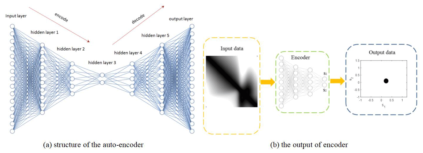
The computer hardware configuration used in this paper is as follows: the CPU is an Inter Core i9-9700, which has a highest computing frequency is 3.0 GHz. The computer memory is 32 GB, and the GPU is an NVIDA Quadro P2200. For the 20 000 samples of the mechanism library, the training time of the auto-encoder on the MATLAB platform is about 2 h. Once the network is trained, the innermost code layer, indicated by hidden layer 3 in Fig. 8a, represents the two-dimensional compressed results of the CAD feature. With the encoder, each of the 50×50-dimensional CAD matrixes can be compressed into a two-dimensional feature, as is represented by (s1,s2) in Fig. 8b.
Figure 9 shows the compressed features of the CAD features of the entire trajectories in the library. Each point represents a trajectory of a mechanism. The distance between two points represents the similarity of the two trajectories. The closer the distance between the two points, the more similar the shape of the trajectories of the corresponding two mechanisms is. On the contrary, the farther the distance between the two points, the greater the shape difference of the mechanism trajectory.
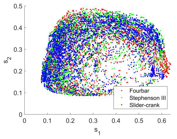
Figure 9Compressed CAD features of the library; the points with red, green, and blue colors represent four-bar type, Stephenson III, and slider-crank mechanisms, respectively
For further illustration, three example points denoted by C1, C2, and C3 are selected in the compressed feature space as shown in Fig. 10. It is obvious that C2 is much closer to C3 than C2; meanwhile, the shape of the mechanism trajectory corresponding to C2 is similar to that represented by C3 while clearly different from the mechanism trajectory of C1. Therefore, the distance between points in the compressed feature space reflects the similarity of their corresponding mechanism trajectories.
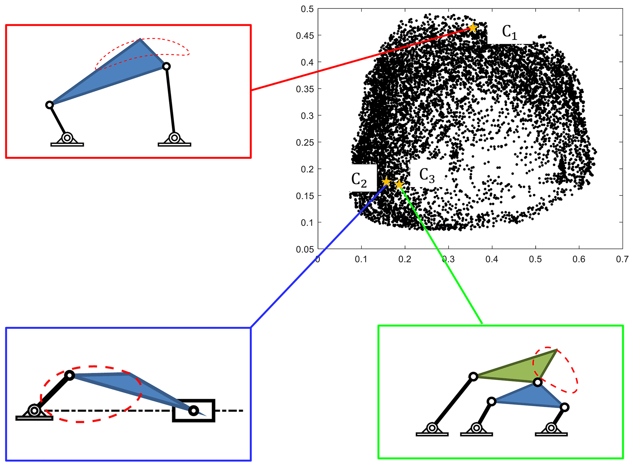
Figure 10Three points in the compressed CAD feature space and their corresponding mechanism trajectories.
With the auto-encoder presented in the previous section, when given a rehabilitation movement trajectory, the target trajectory is first compressed by the auto-encoder to obtain the two-dimensional compression feature. Then, the compressed feature is compared with the compression feature of the database mechanism trajectory. The designer only needs to search for some available points near the target feature points, and the corresponding mechanism of these points can be used as the mechanism of the rehabilitation robot. Therefore, with CAD and library, the rehabilitation design problem is turned into a database search problem. In this paper, Euclidean distance is used to calculate the similarity of two points:
where R is the Euclidean distance between the two points, and (s1i,s2i) and (s1j,s2j) are the two-dimensional compressed features of point i and point j, respectively. The smaller the value of R is, the closer the distance between the two points is, i.e., the higher the similarity between the two trajectories.
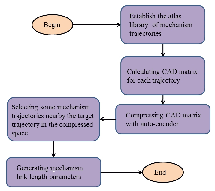
Based on the knowledge above, the steps of our novel approach to design a 1-DOF rehabilitation robot mechanism are given below:
-
Generate the library database involving sample mechanism trajectories with known parameters and construct their CAD matrixes.
-
Compress the dimension of the CAD of sample trajectories with the auto-encoder to obtain compressed features of CAD.
-
When given a target trajectory, calculate the compressed CAD feature through the auto-encoder.
-
Choose some points near to the target and output the mechanism linkage parameters.
It is worth pointing out that the time investment for steps 1 and 2 is for just one time. When a target trajectory is given, the search time is within 2 min. The flowchart of this design process is shown in Fig. 11.
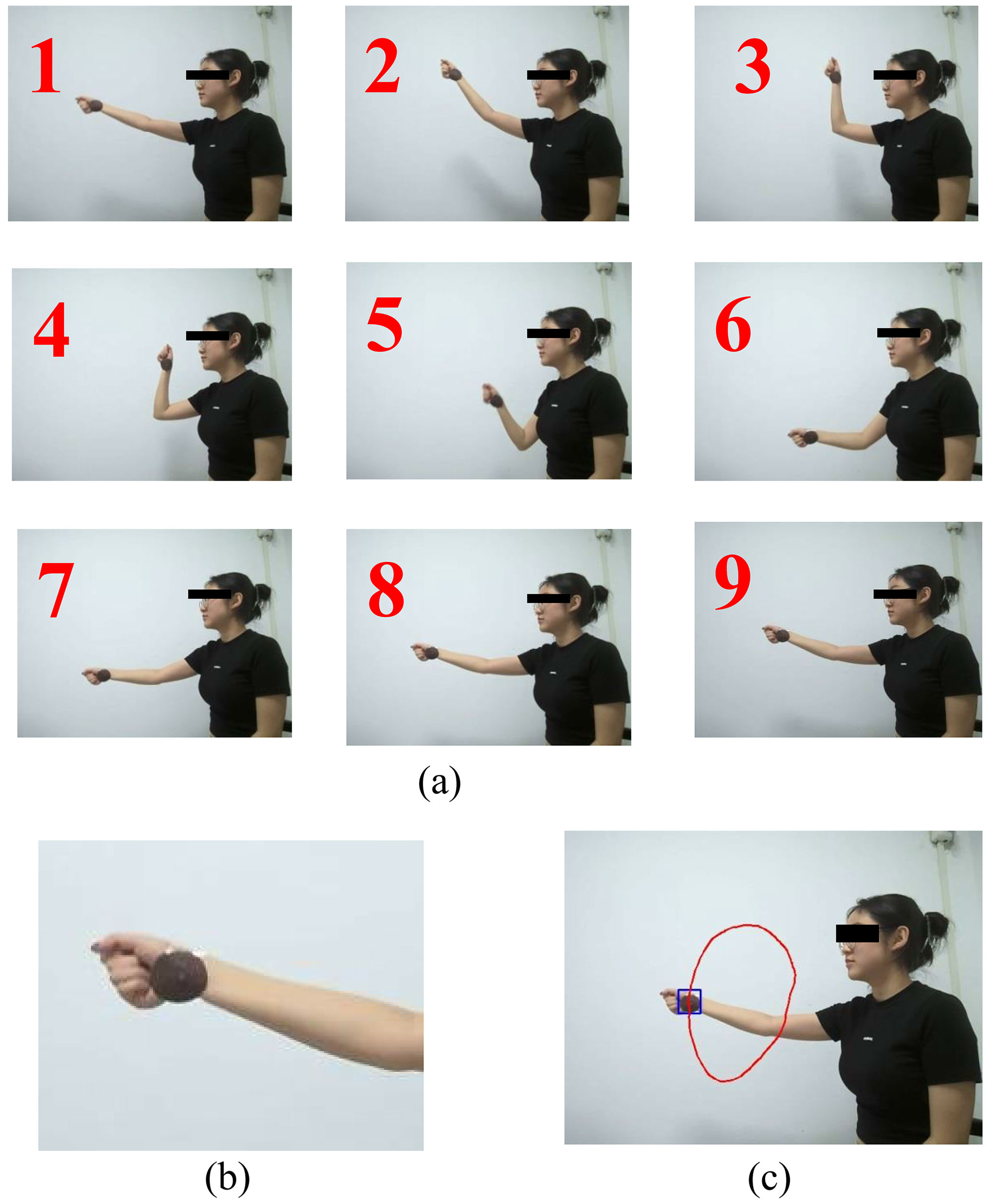
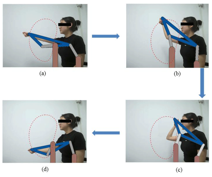
To verify the effectiveness of the proposed method, a typical rehabilitation task – circle-tracing training (Sanchez et al., 2006) – is taken as an example to design a 1-DOF end-effector rehabilitation robot. As discussed in Sect. 2, the shape of the rehabilitation trajectory remains nearly the same when subjects with different body dimensions perform the same rehabilitation task. Hence, our synthesis algorithm is task specific instead of subject specific. The circle-tracing training is a planar trajectory, taken from a specific subject and shown in Fig. 12a.
In order for subjects to collect their trajectories at home, portable visual devices can be used to capture the target trajectory, whose precision has been proven feasible in the context of rehabilitation trajectory acquisition in our previous work (Chen et al., 2020). The portable device is a Surface Pro 7, whose rear camera is utilized to capture the trajectory of motion. The camera has 8 megapixels, which can provide a sampling frequency of 30 fps (frames per second) and tracking accuracy of 1 mm. To obtain the wrist trajectory, we use a marker attached to the user's wrist joint for stable and precise motion tracking, as shown in Fig. 12b. More details on the tracking processing can be found in our previous work (Chen et al., 2020). When capturing the motion track of hand, the user's wrist should be kept parallel with the camera to guarantee the trajectory to be a planar trajectory. The trajectory of the wrist marker is shown as the red line in Fig. 12c.
By using the design method proposed in this paper, six groups of different mechanisms which have similar trajectories to the training motion are presented in Fig. 13; the linkage parameters of these mechanisms are presented in Table 1. The R in Table 1 is the distance of compressed CAD between the mechanism curve and the wrist motion trajectory, which represents the similarity of two trajectories.
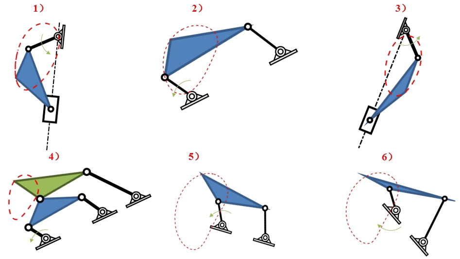

From Table 1 we can notice that the R values of the six groups of mechanisms are all close to 0, which means that their trajectories are close to the wrist trajectory of rehabilitation training. This result can also be verified by comparing the red curves in Figs. 13 and 12c. Besides, Table 1 also shows that the link length ratios are different from each other, indicating that these mechanisms have different relative dimensional types.
To further verify that these obtained mechanisms can track the movement trajectory of the human wrist joint in the circle-tracing training process, the fifth mechanism in Fig. 13 is taken as an example to build the three-dimensional simulation model. The kinematic simulation results are shown in Fig. 14. It can be seen that the motion path of the mechanism can well track the position of the human wrist joint in the circle-tracing training process. These results demonstrate that our approach proposed in this paper is applicable to designing a 1-DOF rehabilitation robot, and multiple groups of solutions of different dimensional types can be obtained.
In this paper, we propose a novel mechanical synthesis approach for a 1-DOF rehabilitation robot mechanism. First, chord angle descriptor is proposed to eliminate the effect of noise and similar transformation such as rotation, translation, and scaling of the trajectory to avoid pseudo mechanism solutions of identical relative link dimensions but merely differing by pose and size. Next, an auto-encoder algorithm is employed to build a clustered library of the shape of the mechanism path by varying relative link parameters to transform the mechanism design problem into a shape retrieval problem. Finally, an example is provided in the end to demonstrate that the approach can be applied to upper-limb rehabilitation mechanism design.
While this paper focuses on the kinematic synthesis of the rehabilitation mechanism and demonstrates that the synthesized path naturally fits the target rehabilitation trajectory, in the future work we will take the mechanism dynamics into consideration to guarantee the quality of interactive force with the implementation of control algorithm and perform clinical trials to validate the therapeutic effect of the synthesized mechanism.
The link to our code and data cannot be provided here but can however be made available upon request to the corresponding author.
The formulas in this paper are mainly derived by WW. XS and PC provided the facility for experiment and is responsible for data processing. The project of this paper is supported by XL, who organized the whole structure of this paper and provided the financial funding.
The contact author has declared that neither they nor their co-authors have any competing interests.
Publisher's note: Copernicus Publications remains neutral with regard to jurisdictional claims in published maps and institutional affiliations.
The work has been financially supported by the National Natural Science Foundation of China (grant nos. 51805449 and 62103291), Sichuan Science and Technology Programs (grant nos. 2021ZHYZ0019 and 2022YFS0021), and 1 3 5 project for 45 disciplines of excellence, West China Hospital, Sichuan University (grant nos. ZYYC21004 and ZYJC21081).
This paper was edited by Zi Bin and reviewed by four anonymous referees.
Adamek, T. and Connor, N. E. O.: A multiscale representation method for nonrigid shapes with a single closed contour, IEEE T. Circ. Syst. Vid., 14, 742–753, https://doi.org/10.1109/TCSVT.2004.826776, 2004.
Alajlan, N., El Rube, I., Kamel, M. S., and Freeman, G.: Shape retrieval using triangle-area representation and dynamic space warping, Pattern Recogn., 40, 1911–920, https://doi.org/10.1016/j.patcog.2006.12.005, 2007.
Aprile, I., Germanotta, M., Cruciani, A., Loreti, S., Pecchioli, C., Cecchi, F., Montesano, A., Galeri, S., Diverio, M., Falsini, C., Speranza, G., Langone, E., Papadopoulou, D., Padua, L., and Carrozza, M. C.: Upper Limb Robotic Rehabilitation After Stroke: A Multicenter, Randomized Clinical Trial, J. Neurol. Phys. Ther., 44, 3–14, 2020.
Bertani, R., Melegari, C., De Cola, M. C., Bramanti, A., Bramanti, P., and Calabrò, R. S.: Effects of robot-assisted upper limb rehabilitation in stroke patients: a systematic review with meta-analysis, Neurol. Sci., 38, 1561–1569, https://doi.org/10.1007/s10072-017-2995-5, 2017.
Cao, Y., Zhang, Z., Czogiel, I., Dryden, I., and Wang, S.: 2D nonrigid partial shape matching using MCMC and contour subdivision, CVPR 2011, Conference on Computer Vision and Pattern Recognition (CVPR), Colorado Springs, CO, USA, 20–25 June 2011, 2345–2352, https://doi.org/10.1109/CVPR.2011.5995588, 2011.
Caproni, S. and Colosimo, C.: Movement disorders and cerebrovascular diseases: from pathophysiology to treatment, Expert Rev. Neurother., 17, 509–519, https://doi.org/10.1080/14737175.2017.1267566, 2017.
Chen, P., Dong, D., Lv, H., and Zhu, L.: A User Motion Data Acquisition and Processing Method for the Design of Rehabilitation Robot With Few Degrees-of-Freedom, ASME J. of Medical Diagnostics, 3, 021104, https://doi.org/10.1115/1.4046320, 2020.
Defebvre, L. and Krystkowiak, P.: Movement disorders and stroke, Revue Neurologique, 172, 483487, https://doi.org/10.1016/j.neurol.2016.07.006, 2016.
Deshpande, S. and Purwar, A.: A Machine Learning Approach to Kinematic Synthesis of Defect-Free Planar Four-Bar Linkages, J. Comput. Inf. Sci. Eng., 19, 021004, https://doi.org/10.1115/1.4042325, 2019.
Faisal, A. A., Selen, L. P. J., and Wolpert, D. M.: Noise in the nervous system, Nat. Rev. Neurosci., 9, 292–303, https://doi.org/10.1038/nrn2258, 2008.
Harris, C. M. and Wolpert, D. M.: Signal-dependent noise determines motor planning, Nature, 394, 780–784, https://doi.org/10.1038/29528, 1998.
Holden, D.: Robust solving of optical motion capture data by denoising, ACM T. Graphic., 37, 165, https://doi.org/10.1145/3197517.3201302, 2018.
Kan, P., Huq, R., Hoey, J., Goetschalckx, R., and Mihailidis, A.: The development of an adaptive upper-limb stroke rehabilitation robotic system, J. Neuroeng. Rehabil., 8, 33, https://doi.org/10.1186/1743-0003-8-33, 2011.
Kemna, S., Culmer, P. R., Jackson, A. E., Makower, S., Gallagher, J. F., Holt, R., Cnossen, F., Cozens, J. A., Levesley, M. C., and Bhakta, B. B.: Developing a user interface for the iPAM stroke rehabilitation system, 2009 IEEE International Conference on Rehabilitation Robotics, 23–26 June 2009, 879–884, https://doi.org/10.1109/ICORR.2009.5209507, 2009.
Li, Q., Wang, D., Du, Z., Song, Y., and Sun, L.: sEMG Based Control for 5 DOF Upper Limb Rehabilitation Robot System, 2006 IEEE International Conference on Robotics and Biomimetics, 17–20 December 2006, 1305–1310, https://doi.org/10.1109/ROBIO.2006.340117, 2006.
Marimont, R. B. and Shapiro, M. B.: Nearest Neighbour Searches and the Curse of Dimensionality, IMA J. Appl. Math., 24, 59–70, https://doi.org/10.1093/imamat/24.1.59, 1979.
Mokhtarian, F., Abbasi, S., and Kittler, J.: Efficient and Robust Retrieval by Shape Content through Curvature Scale Space, in: Image Databases and Multi-Media Search, Series on Software Engineering and Knowledge Engineering, 8, edited by: Arnold, S. and Ramesh, J., World Scientific, 51–58, https://doi.org/10.1142/9789812797988_0005, 1998.
Nabout, A. A. and Tibken, B.: Object Shape Description Using Haar-Wavelet Functions, 2008 3rd International Conference on Information and Communication Technologies: From Theory to Applications, Damascus, Syria, 7–11 April 2008, 1–6, https://doi.org/10.1109/ICTTA.2008.4530076, 2008.
Narayan Arya, K., Verma, R., Garg, R. K., Sharma, V. P., Agarwal, M., and Aggarwal, G. G.: Meaningful Task-Specific Training (MTST) for Stroke Rehabilitation: A Randomized Controlled Trial, Top. Stroke Rehabil., 19, 193–211, https://doi.org/10.1310/tsr1903-193, 2012.
Ng, A.: Sparse autoencoder, CS294A Lecture notes, 72, 1–19, 2011.
Rodrigues, L. A. O., Moraes, V. P., and Gonçalves, R. S.: ReGear: an upper and lower limb simultaneous system for stroke rehabilitation, J. Braz.Soc. Mech. Sci., 43, 1–18, https://doi.org/10.1007/s40430-021-03199-8, 2021.
Rosati, G., Gallina, P., and Masiero, S.: Design, Implementation and Clinical Tests of a Wire-Based Robot for Neurorehabilitation, IEEE T. Neur. Sys. Reh., 15, 560–569, https://doi.org/10.1109/TNSRE.2007.908560, 2007.
Sanchez, R. J., Liu, J., Rao, S., Shah, P., Smith, R., Rahman, T., Cramer, S. C., Bobrow, J. E., and Reinkensmeyer, D. J.: Automating arm movement training following severe stroke: functional exercises with quantitative feedback in a gravity-reduced environment, IEEE T. Neur. Sys. Reh., 14, 378–389, https://doi.org/10.1109/TNSRE.2006.881553, 2006.
Sutter, K., Oostwoud Wijdenes, L., van Beers, R. J., and Medendorp, W. P.: Movement preparation time determines movement variability, J. Neurophysiol., 125, 2375–2383, https://doi.org/10.1152/jn.00087.2020, 2021.
Theriault, A., Nagurka, M., and Johnson, M. J.: Design and Development of an Affordable Haptic Robot with Force-Feedback and Compliant Actuation to Improve Therapy for Patients with Severe Hemiparesis, IEEE T. Haptics, 7, 161–174, https://doi.org/10.1109/TOH.2013.51, 2014.
Torres-Moreno, J. L., Cruz, N. C., Álvarez, J. D., Redondo, J. L., and Giménez-Fernandez, A.: An open-source tool for path synthesis of four-bar mechanisms, Mech. Mach. Theory, 169, 104604, https://doi.org/10.1016/j.mechmachtheory.2021.104604, 2022.
Zhang, D. and Lu, G.: Shape-based image retrieval using generic Fourier descriptor, Signal Process.-Image, 17, 825–848, https://doi.org/10.1016/S0923-5965(02)00084-X, 2002.
Zhao, P., Li, X., Zhu, L., Zi, B., and Ge, Q. J.: A novel motion synthesis approach with expandable solution space for planar linkages based on kinematic-mapping, Mech. Mach. Theory, 105, 164–175, https://doi.org/10.1016/j.mechmachtheory.2016.06.021, 2016.
Zhao, P., Zhang, Y., Guan, H., Deng, X., and Chen, H.: Design of a Single-Degree-of-Freedom Immersive Rehabilitation Device for Clustered Upper-Limb Motion, J. Mech. Robot., 13, 031006, https://doi.org/10.1115/1.4050150, 2021.
Zhu, L., Lv, H., Li, L., and Xu, X.: A User-Driven Design Framework for Coupled-Serial-Chain Mechanism Synthesis for Assisting Sit-to-Stand Motion, ASME J. Medical Diagnostics, 3, 021106, https://doi.org/10.1115/1.4046322, 2020.