the Creative Commons Attribution 4.0 License.
the Creative Commons Attribution 4.0 License.
 | 14 Mar 2022
Flow characteristics analysis of a balanced valve distribution double-row axial piston pump
Zhipeng Li
Haishun Deng
Qiangman Chen
Chuanli Wang
Kaiping Zhao
To study the flow characteristics of a new swashplate rotary valve distribution double-row axial piston pump, an instantaneous flow model was developed for the pump, the influences of structural parameters on the flow pulsation and uneven coefficient of flow were determined, and the ideal plunger distribution parameters were derived. On this basis, a valve distribution model was developed for the pump, the flow superposition process in the plunger cavity was analyzed, and the high-speed switching valve's control strategy was optimized. Additionally, the effects of parameters such as the plunger motion frequency, the plunger cavity's dead zone volume, the spool valve's preloading force, and the spool's equivalent mass on the flow characteristics were studied. The results show that the new pump had a small flow pulsation when there were five plungers in both the inner and outer rows and the dislocation angle was 18∘. The plunger's reverse-suction effect at the moment when the discharge valve opened and the suction valve closed and the plunger cavity's dead zone volume size were the primary factors affecting the size of the pump's flow spike. The discharge valve's opening was delayed by 3 ms to be consistent with the suction valve's closing time; for this case, the flow peak was small and the volumetric efficiency was the highest. The discharge valve began to close 2 ms early and closed completely at the critical point when the plunger transferred from the discharge stroke to the suction stroke, which helped the suction valve to open on time and improved the pump's oil absorption capacity. The active opening and closing control of the discharge valve improved the coordination of the flow distribution to a large extent, reduced the hysteresis of the suction valve, and ultimately improved the pump's volumetric efficiency and flow stability. The results of this study can provide theoretical guidance for the flow control of balanced double-row axial piston pumps with valve distribution.
- Article
(7776 KB) - Full-text XML
- BibTeX
- EndNote


Axial piston pumps with high pressures, high flow rates, and compact structures are core power elements in many fields, such as aerospace, metallurgy, ships, and engineering machinery (Casoli et al., 2019; Manco et al., 2002). As advances are made in industrial technology, the pumps' actual working conditions are becoming increasingly complex, and the requirements for hydraulic components, especially plunger pumps, are becoming stricter (Zu et al., 2016). However, existing end-matched axial piston pumps are sensitive to pollution and are constrained by the limit [pv] values that the end-matched subsets can withstand, making it difficult to continue to increase their displacements and speeds. Multi-pump coaxial drives are necessary for cases with higher power requirements (Pan et al., 2016; Zhang et al., 2021; Wang et al., 2001). The swashplate's inclination angle and the asymmetry of the flow distribution plate's high-pressure area lead to unbalanced forces in the common swashplate axial piston pumps (Deng et al., 2019, 2020). Valve distribution axial piston pumps have high output pressures and are not sensitive to pollution, but they have large flow pulsations and poor self-priming abilities. In addition, there are serious hysteresis problems in both their discharge valves and suction valves (Yu et al., 2020; Ma et al., 2017). How to further reduce the flow pulsation, increase the power, and improve the force situation of the piston pump has become a challenging research topic in this field.
Zhang et al. (2020) and Jiang et al. (2017) designed a single swashplate double-row axial piston pump, discussed the influence of flow pulsation on structural parameters such as the number and distribution of the plungers, and developed a flow pulsation variation law for through-shaft double-row axial piston pumps. Deng et al. (2014, 2016) proposed a hydraulic pressure-balanced two-row disc with a flow axial piston pump, which had two interlocking inner and outer swashplates to support the inner and outer rows of plungers, respectively. The instantaneous flows of the inner and outer rows of plungers could cancel each other, thus significantly reducing the flow pulsation and allowing the pump to easily achieve a force balance.
To investigate the valve flow distribution, Ante and Nikola (2009) and Ivica et al. (2014) analyzed the check valve operation in the suction and discharge stages of a high-pressure reciprocating pump, derived an analytical expression to determine the actual pump flow rate, and predicted the actual discharge with an error of less than 3 %. Zhu et al. (2018) and Qian et al. (2019) proposed a kind of axial piston hydraulic motor pump with a double inclined spiral valve distribution, using the phase relationship between two swashplates to obtain the variable, thereby overcoming a traditional valve distribution pump's limitation in easily obtaining the variable. Yan et al. (2020) developed a simulation model for a high-speed valve distribution system and studied the high-speed valve's dynamic flow characteristics. The effects of both the cone and ball valve spool configurations on the flow characteristics of the system were primarily reflected in the spool's closing stroke. They concluded that the cone valve's inlet flow performance was better than that of the ball valve and that the cone valve's output pressure pulsation and spool action hysteresis were significantly less than that for the ball valve.
Zhu et al. (2018) designed a variable-stiffness spring reciprocating pump automatic cone valve and investigated the effects of spring stiffness type on the valve's opening and closing hysteresis. They concluded that the reduced function variable-stiffness spring improved the dynamic performance of the valve. Li et al. (2013) studied the flow characteristics of a high-frequency reciprocating pump with a check valve distribution and analyzed the reasons why the output flow of the pump was still bottlenecked despite the fact that the frequency response of the check valve met the system requirements. They concluded that there was a large disparity between the volumetric efficiencies for the passive and active flow distributions.
To investigate the flow characteristics, Lai et al. (2020) analyzed the time–frequency domain characteristics of a nuclear main pump's pressure pulsations, discussed the operating conditions' influence on the pressure pulsation characteristics, and concluded that the operating volume flow was the primary factor causing the pressure pulsations. Huang et al. (2014) proposed a double-acting symmetrical piston pump with a fixed displacement to solve the problem of unequal flow in non-symmetrical cylinders in a closed hydraulic circuit and obtained a basic equation of flow distribution method for the pump in the loop. The research described above laid a good foundation for studying flow characteristics for axial piston pumps with double-row end face distributions and traditional valve distribution piston pumps. Guo et al. (2016) and Zhao et al. (2017) proposed a sliding valve distribution radial piston pump (SVDRPP). A new method for dispensing oil to the piston chamber, even when there was a slide valve, was developed, and the flow characteristics of the SVDRPP were investigated. Luo et al. (2011) presented a novel axial piston water pump with a piston valve, which carried the flow distribution all the way to the drain and sucked water through the interactions of the pistons. However, there was a large amount of leakage, and the volumetric efficiency was 74.7 %. Dong et al. (2019) presented a radial piston pump with through-shaft driving and a valve plate distribution, then designed its proportional control system, and then analyzed the flow pulsation process. Liu et al. (2017) and Wen et al. (2020) designed a new balanced axial piston pump and a double-swashplate multi-row axial piston motor, analyzed the influence of different parameters on the output characteristics of the pump as well as the motor experimental data, and verified the feasibility of the new pump and motor using the structural principle.
In recent years, advances in high-speed on–off valve technology have led to the emergence of digital valve flow distribution technology (Zhong et al., 2019; Zhang et al., 2018). To improve the valve flow response speed and control accuracy, the digital valve flow distribution control strategy can be actively optimized to compensate for the lag in the valve flow distribution, thus significantly improving the dynamic valve flow distribution characteristics (Zhong et al., 2021a, b). Digital displacement fluid power pumps and motors are promising candidates for revolutionizing the efficiency of fluid power systems, which have traditionally suffered from poor efficiencies, especially at partial loading. Roemer et al. (2013) designed a fast-switching efficient seat valve for digital displacement fluid power pumps and motors and manufactured a prototype valve that achieved good experimental results. Pedersen et al. (2018) presented a flow and pressure control strategy for a fixed-speed digital displacement pump unit and used simulations to show the influence of a flow–pressure compromise on the optimal solution. The results showed the applicability of the control strategy and indicated that a much higher energy efficiency could be obtained with only a minor decrease in the tracking performance for the pressure control.
Based on existing research, a new balanced valve distribution double-row axial piston pump is proposed in this paper to achieve semi-active flow distribution with high-speed on–off valve technology. The new pump's structure and working principle were determined, the influences of the plunger distribution and the numbers of inner and outer row plungers on the pump's flow characteristics were analyzed, and better plunger distribution parameters were derived. On this basis, an AMESim flow distribution model for the whole pump was developed, and the discharge valve's opening and closing strategy was optimized. Then, the optimized control strategy was used to study the effects of certain parameters, such as the plunger frequency, the plunger cavity's dead zone volume, the spool spring's preloading force, and the spool's equivalent mass, on the flow distribution characteristics.
The structure of the valve distribution double-row axial piston pump is shown in Fig. 1. The cylinder body was fixed and the swashplate rotated. The swashplate was composed of two rows of internal and external interlacing inclined planes, and each inclined plane was provided with a row of plungers. An angle sensor was attached to the end of the pump shaft to detect the swashplate's rotation angle. Taking the installation sizes of the check valves into account, each plunger was equipped with a common check valve as a suction valve near the ball position, while a two-position two-way high-speed switching valve was installed at the end of each plunger chamber to achieve active control of the discharge port according to the swashplate's angle. When the swashplate rotated, the volume of the plunger chamber located in the suction area increased, the suction valve opened, the high-speed switching valve closed, and oil suction began. When the volume of the plunger chamber located in the oil discharge area decreased, the high-speed switching valve opened and oil discharge began. Because the staggered swashplate structure caused the suction and discharge cycles of the inner and outer row plungers to be staggered, the pump's overturning torque could be balanced during operation and the flow pulsation could be reduced significantly. In addition, variable function was achieved by replacing the two-position two-way high-speed switching valve with a two-position three-way switching valve.
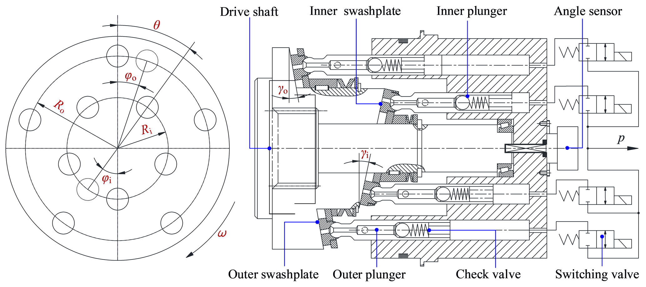
Figure 1Structural principles of the balanced valve distribution double-row axial piston pump.
There were many plungers in the balanced valve distribution double-row axial piston pump. The number and distribution of plungers in a pump can significantly influence the flow pulsation. Therefore, it was necessary to develop an instantaneous flow model for the pump, to study the influence of structural parameters on the flow pulsation and the flow unevenness coefficient, and then to obtain the ideal number of plungers and their corresponding distribution parameters. A balanced double-row axial piston pump is different from a single-swashplate double-row axial piston pump, which can be regarded as the superposition of two rows of misaligned 180∘ single-row axial piston pumps. By taking the maximum upper dead point of the outer row's piston cavity volume as the starting point of the outer row calculations and taking the maximum upper dead point of the inner row's piston cavity volume as the starting point of the inner row calculations, the instantaneous flow rates generated by the inner and outer rows of pistons could be expressed by Eqs. (1) and (2), respectively:
In Eqs. (1) and (2), Qsi and Qso are the instantaneous flow rates for the inner and outer plungers, respectively, in units of liter per minute, Fi and Fo are the instantaneous peak flow rates for the inner and outer plungers, respectively, in units of liter per minute, αi and αo are the characteristic parameters of the inner and outer plungers, respectively, in units of radians, and φi and φo are the angles of rotation, in units of rad, for the inner and outer plungers, respectively, relative to the calculation starting point.
Equations (1) and (2) show that the instantaneous flow rates generated by the inner and outer plungers were approximately cosine curves. To reduce the pulsation, the amplitudes of the inner and outer discharge flows could be equal, causing the peaks and valleys of the instantaneous flows to superimpose over each other and abate.
The flow unevenness coefficient, δq, which described the extent of the flow pulsation, could be calculated using Eq. (3):
In Eq. (3), Qsmax is the instantaneous maximum flow rate, Qsmin is the instantaneous minimum flow rate, and Qpva is the average flow rate.
The average flow rate in the plunger chamber could be calculated using Eqs. (4)–(6):
In Eqs. (4), (5), and (6), QBvi is the inner average flow rate, in units of liter per minute, di is the inner plunger diameter, in units of millimeters, zi is the number of inner plungers, Ri is the radius of the inner plunger distribution circle, in units of millimeters, γi is the inner swashplate inclination angle, in units of ∘, QBvo is the outer average flow rate, in units of liter per minute, do is the outer plunger diameter, in units of millimeters, zo is the number of outer plungers, Ro is the radius of the outer plunger distribution circle, in units of millimeters, γo is the outer swashplate inclination angle, in units of ∘, and QBv is the inner and outer average total flow rate, in units of liter per minute.
For the convenience of control and reducing pulsation, it was assumed that the total number of plungers could be represented by z and that the number of inner plungers, zi, was equal to the number of outer plungers, zo. Thus, , so that and .
3.1 Odd number of plungers in both the inner and outer rows
The instantaneous flow rates generated by the inner and outer rows of pistons could be expressed by Eqs. (7) and (8):
In Eqs. (7) and (8), Ai and Ao represent the cross-sectional areas inside the inner and outer row plunger cavities, respectively, in units of mm2, and ω is the angular velocity of the oblique spiral, in units of radians per minute. Since the inner and outer swashplates intersected by 180∘ and the dislocation angle between the adjacent inner and outer rows of plungers was θ, Eq. (9) could be obtained:
Equation (10) was obtained by replacing φo in Eq. (8) with φi, where φi represents the rotation angle of the cylinder or swashplate:
3.2 Even number of plungers in both the inner and outer rows
At this time, the instantaneous flow rates generated by the inner and outer rows of pistons could be expressed by Eqs. (11) and (12):
Since the inner and outer swashplates intersected by 180∘ and the dislocation angle between the adjacent inner and outer rows of plungers was θ, Eq. (13) could be obtained:
Equation (14) was obtained by substituting Eq. (13) into Eq. (12):
Finally, the formula for the total instantaneous flow, Qs, of the balanced valve distribution double-row axial piston pump is shown in Eq. (15):
This study selected the numbers of inner and outer rows of plungers to be equal; that is, . Therefore, Eqs. (7), (8), (10), and (14) show that the flow equations for the inner and outer rows of plungers are the same and that the flow was positive. They also show that both are piecewise cosine functions; that is, the flow curves for the inner and outer rows of plungers had the same shapes and the same periods but different phases. In addition, the design of the double-row pump, both inside and outside, utilized the concept of equal flow design. A reasonable design dislocation angle, θ, caused the flow curves for the inner and outer rows of plungers to be staggered half a cycle, causing the minimum value of the inner flow to always correspond to the maximum value of the outer flow and the maximum value of the inner flow to always correspond to the minimum value of the outer flow. At this point, the value of the flow unevenness coefficient, δq, in Eq. (3) was at a minimum. This analysis indicates that, to reduce the pulsation, the amplitudes of the inner and outer discharge flows were set equal, and Eq. (16) was obtained based on the previous equations:
Since the numbers of inner and outer plungers were equal, Eq. (17) was obtained:
Therefore, the inner and outer plungers' diameters, distribution circle radii, and swashplate inclination angles should satisfy the relationship in Eq. (18):
In Eq. (18), di and do are the diameters of the inner and outer row plungers, respectively, in units of millimeters.
3.3 Instantaneous flow and pulsation calculation
In general, zi≥4, zo≥4, , and zi=zo, so that four primary cases could be investigated: , , , and . When the number of inner and outer row plungers was four and six, the flow characteristic curves were calculated using Eqs. (3)–(6) and (11)–(14) in Matlab, as shown in Figs. 2 and 3, respectively.

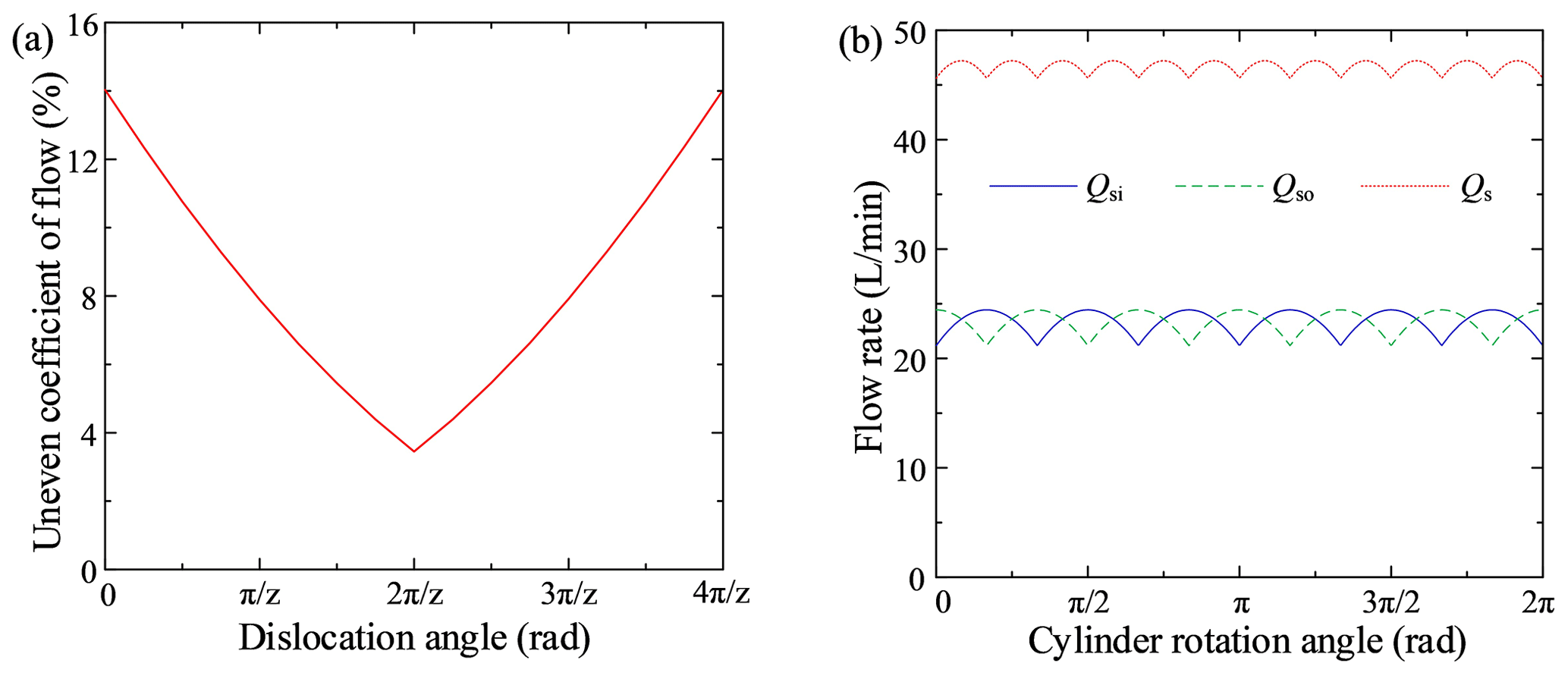
Figure 2a shows that the dislocation angle, θ, ranged from 0 to (z=8) and that the uneven coefficient of flow decreased and then increased as the dislocation angle increased, creating a V-shaped profile. When ∘, the uneven coefficient of flow was at its minimum value, 7.81 %. Figure 2b shows that when θ=45∘, the pulsation period for both the inner and outer rows was , the phase difference between the inner and outer rows' flow curves was , the peaks and valleys of the instantaneous flows superimposed over each other and then abated, and the total flow's pulsation period was .
Figure 3a shows that the dislocation angle, θ, ranged from 0 to (z=12) and that the uneven coefficient of flow had a V-shaped profile similar to that in Fig. 2a. When ∘, the uneven coefficient of flow was at its minimum value, 3.45 %. Figure 3b shows that when θ=30∘, the pulsation period for both the inner and outer rows was , the phase difference between the inner and outer rows' flow curves was , the peaks and valleys of the instantaneous flow superimposed over each other and then abated, and the total flow's pulsation period was .
When the numbers of inner and outer row plungers were 5 and 7, the flow characteristic curves were calculated using Eqs. (3)–(10) in Matlab, as shown in Figs. 4 and 5, respectively.
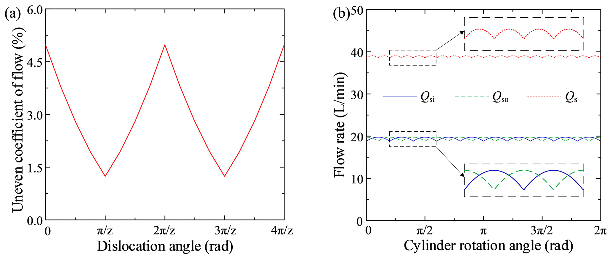
Figure 4a shows that the dislocation angle, θ, ranged from 0 to (z=10) and that the uneven coefficient of flow's profile created a W shape as the dislocation angle increased. When ∘ and ∘, the uneven coefficient of flow was at its minimum value, 1.24 %. Figure 4b shows that when θ=18∘ or θ=54∘, the pulsation period for both the inner and outer rows was , the phase difference between the single inner and outer rows' flow curves was , the peaks and valleys of the instantaneous flow superimposed over each other and then abated, and the total flow's pulsation period was .
Figure 5a shows that the dislocation angle, θ, ranged from 0 to (z=14) and that the uneven coefficient of flow's profile was W-shaped, as in Fig. 4a. When ∘ and ∘, the uneven coefficient of flow was at its minimum value, 0.63 %. Figure 5b shows that when θ=12.86∘ or θ=38.57∘, the pulsation period for both the inner and outer rows was , the phase difference between the single inner and outer rows' flow curves was , the peaks and valleys of the instantaneous flow superimposed over each other and then abated, and the total flow's pulsation period was .
A comprehensive analysis of Figs. 2 through 4 shows that the flow pulsation was low when there was an odd number of plungers in a single row and that the flow pulsation decreased as the number of plungers increased. By reasonably configuring the dislocation angle, θ, the instantaneous flows' peaks and valleys for the inner and outer rows of the new balanced flow distribution double-row axial piston pump superimposed over each other and then abated. This caused the total flow's pulsation period to be half that of a single row's pulsation period, and a smaller uneven coefficient of flow was obtained. Considering the actual installation space of the plungers, when , the minimum distance between two plungers was 11.8 mm, and there was not enough space to install the high-speed switching valve. Therefore, the final scheme taken was , leading to an uneven coefficient of flow of 1.24 %, a small pulsation, and enough installation space.
Figure 5Flow characteristics (): (a) uneven coefficient of flow and (b) flow curve (θ=12.86∘).
The above theoretical derivation process represents an ideal situation, but it does not consider factors such as the friction force, the dead zone's volume, and the response times of the suction and discharge valves. To examine the influence of the piston pump's structural parameters on its flow distribution characteristics in more detail, a flow distribution model for the pump was constructed based on the flow pulsation analysis with the help of AMESim. Then, the optimized control strategy for the high-speed on–off valve was obtained.
4.1 Model and parameters
As shown in Fig. 6, the inner and outer rows were designed with equal flow rates. The numbers of plungers inside and outside the model were both set to five. The motor simultaneously controlled the inclinations and rotation directions of the inner and outer swashplates and drove the cylinders' inner and outer row of plungers in reciprocating motion. The function f(x,y) was set according to Eqs. (19) and (20) to convert the inner and outer swashplates' inclination angles and the rotation angles of the inner and outer row plungers into inner and outer row plunger displacements, Si and So.
In the model, k1 and k2 were used to set the radii of the inner and outer row distribution circles, respectively, and k3 and k4 were used to set the inclination angles of the inner and outer swashplates, respectively. ki1, ki2, ki3,ki4, and ki5, respectively, represent the initial angles of plungers 1 to 5 in the inner row, and ko1, ko2, ko3, ko4, and ko5, respectively, represent the initial angles of plungers 1 to 5 in the outer row. Plunger 1 in the outer row was set as the reference plunger. The initial angles of the other outer plungers were increased to 72∘ on the basis of the initial angles of the previous plungers, and the initial angles of the inner row plungers were set in the same way.
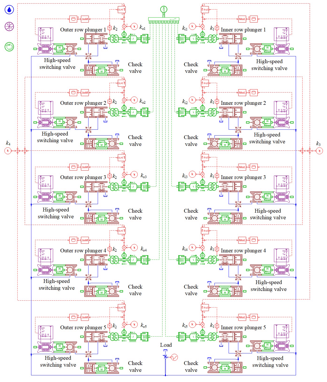
At present, the response time range for a high-speed switching valve can reach 1–3.5 ms (Zhong et al., 2021b; Yang et al., 2016), and its opening and closing speeds are too slow. To make the performance of a high-speed switching valve fit actual working conditions as closely as possible, and because of the high pressure and large flow in the plunger pump, the opening and closing times should not be too small. According to the literature (Zhong et al., 2021b; Yang et al., 2016; Yan, 2015), the suction valve had a ball valve structure, and a one-dimensional table interpolation method was used to control the opening and closing of the high-speed switching valve. The opening and closing times were set to 2 ms. The specific parameter settings are shown in Table 1.
4.2 Analysis of the flow superposition process
The flow superposition process was simulated, and the results are shown in Fig. 7. At the beginning of the calculations, the pump required a certain start-up time to transition from the static state to the stable operation state, so the initial portions of the curves in Fig. 7 were not periodic. Figure 7a shows the flow curves for the plunger dislocation angles θ=0, 18, and 36∘ and shows that the flow curves obtained from the simulation were consistent with the results of the theoretical analysis (Figs. 2–5). However, the simulation curves contained instantaneous flow spikes, and the pulsation waveforms were not as regular as in the theoretical curves.
To further analyze the reasons for the spikes, flow superposition curves for the five groups of plungers in the inner row and the five groups of plungers in the outer row were obtained, as shown in Fig. 7b, c, and d. The figures show that for each group of plungers, the discharge valve opened, while the suction valve closed at the initiation of the backward suction effect. The same angle was fixed for each plunger interval; so, a regular reverse suction spike occurred after the same time interval ( of the rotational period, T). There were five aspiration peaks in one cycle (for the inner rows, they were ci1, ci2, ci3, ci4, and ci5, and for the outer rows, they were co1, co2, co3, co4, and co5). Because of the inner and outer rows' dislocation angle, θ=18∘ ( of the single-row pulsation cycle, ), after the superposition of the internal and external discharge flows, there were five groups of double-inverted suction spikes in the total flow during one rotation cycle, T, and each group of double-inverted suction spikes was separated by three double-row pulsation cycles (a double-row pulsation cycle was ).
In addition, the superimposed graph shows that there were several small flow spikes in the single plunger chamber (including the inner spikes, ai1, ai3, ai4, and ai5, and the outer spikes, ao1, ao2, ao3, ao4, and ao5). However, due to the superposition of multiple plunger curves, most of the small spikes were superimposed over other spikes and abated. For example, the small spikes ai3 and ai4 were canceled somewhat by the large, reversed spike ci5, and the small spikes ao3 and ao4 were offset by the large, reversed spike co5. Some of the small spikes were superimposed and enhanced; for example, ai1 and ai5 superimposed over each other and produced the medium spike bi1, and ao1, ao2, and ao5 superimposed over each other and produced the medium spike bo1. However, the medium spikes bi1 and bo1 were offset by the large spikes do1 and di1, respectively, during the inner and outer plunger flows' stacking mechanism. The superposition and reduction processes for the other spikes were similar to those discussed above. Thus, compared with an ordinary single-row valve distribution piston pump, the balanced distribution double-row axial piston pump had a good flow pulsation abatement mechanism that could effectively reduce the flow pulsation.
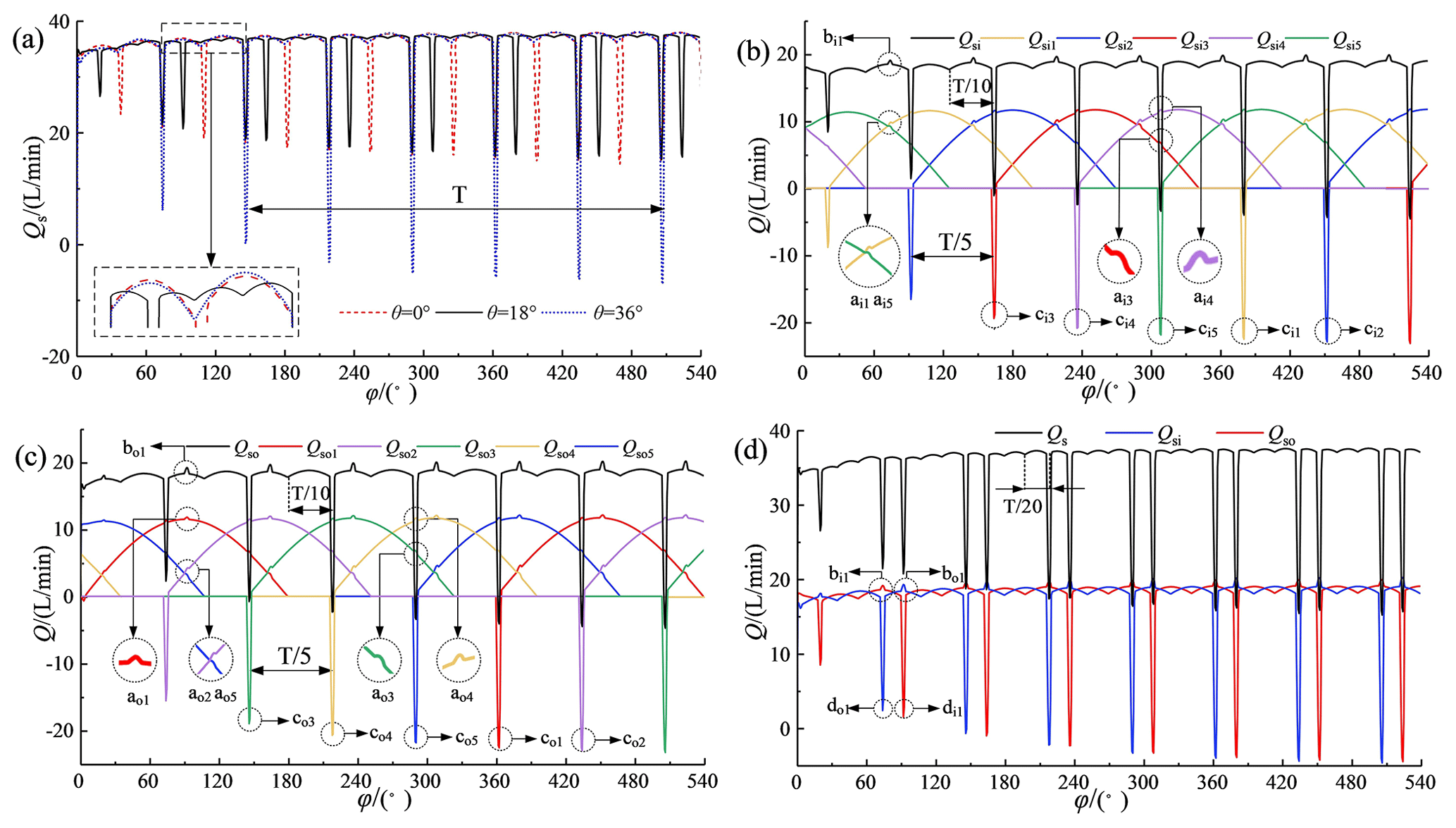
Figure 7Flow superposition curves: (a) influence of dislocation angles, (b) inner flow, (c) outer flow, and (d) total flow.
The above analysis showed that the theoretical calculation results were consistent with the AMESim model's simulation results. Additionally, the valve flow distribution process obtained by simulation was essentially consistent with the valve flow distribution processes from the literature (Zhu et al., 2018; Qian et al., 2019), which further verified the accuracy of the AMESim model. However, the conditions calculated by the theoretical equations were too ideal, and the opening and closing of the flow distribution valves as well as other factors in the actual system would also impact the system's flow characteristics. For this reason, a deeper study of the flow and flow distribution characteristics was conducted with the help of the AMESim multi-physics field simulation model.
4.3 Analysis of the discharge valve's opening and closing strategy
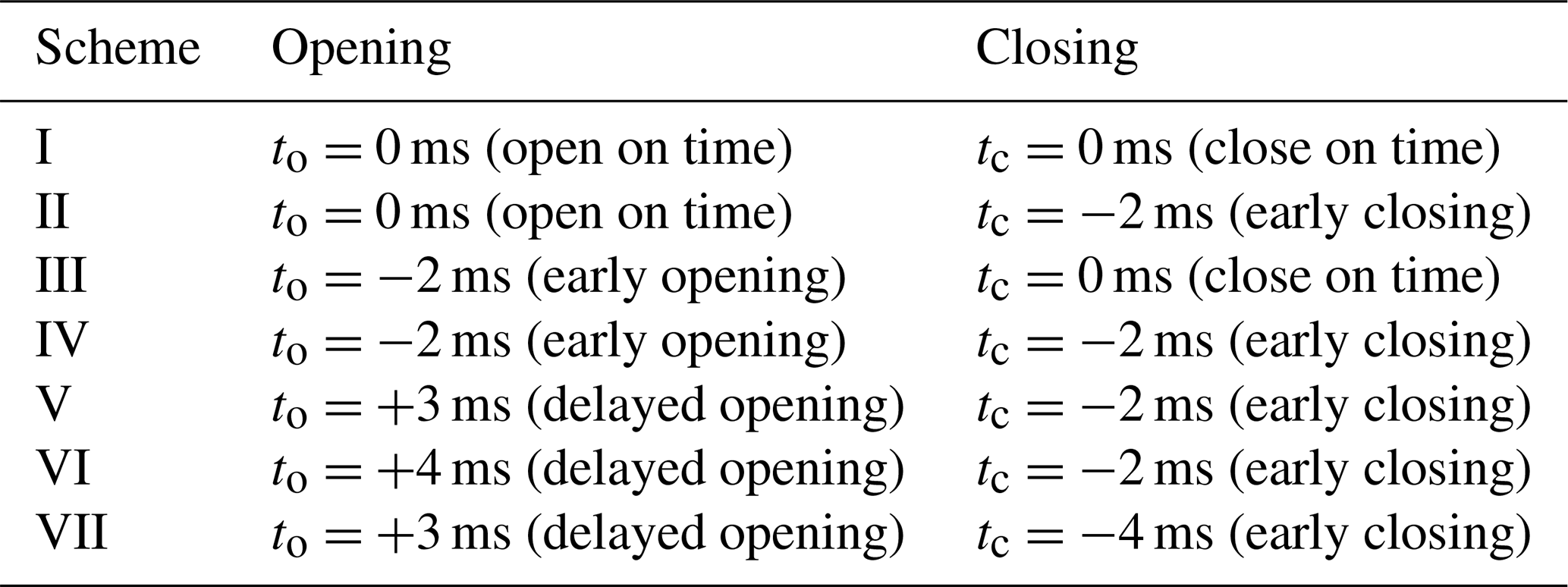
Opening and closing of the discharge valve require a certain amount of time, and delayed closing would affect the opening of the suction valve, which would result in insufficient oil absorption and would thus affect the volumetric efficiency. Research indicated that a delay of 3 ms was consistent with the closing time of the suction valve. At this time, the flow peak was at a minimum. Therefore, to make the selected parameters more representative and to minimize the number of parameter groups, seven combinations were selected for discussion based on the opening and closing times relative to a standard suction and discharge cycle, as shown in Table 2.
The discharge valve's flow and pressure characteristics for different opening and closing strategies are shown in Figs. 8 and 9. These figures show that when the discharge valve was opened on time, as in Schemes I and II, the spikes in flow reduction were small relative to the overall theoretical flow curve. Larger spikes in flow reduction occurred when the discharge valve was opened early, as in Schemes III and IV, and early opening of the discharge valve led to earlier flow spikes. Delayed opening of the discharge valve helped to reduce the flow spikes, as in Scheme V. However, delaying the opening of the discharge valve too much led to blocked discharge, a sharp rise in the plunger chamber pressure, the generation of a positive flow peak at the moment of opening the discharge valve, and violent flow fluctuations, as in Scheme VI. The above phenomenon occurred because at the moment of opening the discharge valve, the suction valve was not closed, or it closed with a lag, which led to liquid from the high-pressure cavity entering the plunger cavity. This resulted in reverse suction, which led to a spike in the flow rate reduction. When the discharge valve opened early, liquid from the high-pressure chamber entered the plunger chamber early and produced reverse suction, thus causing the flow rate spike to appear early and increase. Additionally, delaying the opening of the discharge valve helped to reduce the spike. The flow rate spike was minimized when the delay time coincided with the closing of the suction valve, while a delay time that exceeded the suction valve's closing time caused the drainage to be blocked.
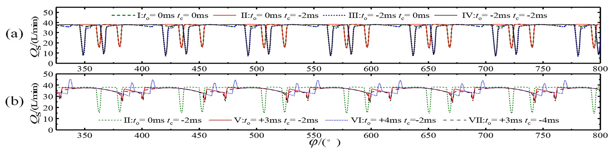
In addition, there was a longer reduction time of flow rate when the discharge valve was closed on time relative to the theoretical flow curve, as in Schemes I and III. This phenomenon occurred because it took 2 ms for the discharge valve to close, resulting in the discharge valve not closing on time when entering the suction stroke. The high pressure in the drain chamber caused the suction valve to open with difficulty, further delaying the opening of the suction valve, which resulted in insufficient suction.
Closing the discharge valve early helped the suction valve to open on time and improved the pump's suction capacity, especially at the critical point when the plunger transferred from the discharge stroke to the suction stroke, and the best effect of completely closing the discharge valve could be achieved. However, closing the discharge valve before the end of the discharge stroke would lead to a plunger chamber squeeze, during which the pressure would rise sharply and the check valve would open with difficulty (such as for Scheme VII).
The valve distribution process mentioned above was essentially the same as the plate flow distribution process. Both controlled the opening and closing of the distribution passageway at the point of reversing the plunger motion. Advanced or delayed opening and closing of the distribution passageway would have an impact on the pressure and flow fluctuations. Its distribution mechanism was equivalent to the plate distribution mechanism in the literature (Zhang et al., 2017).
Figures 8 and 9, along with their discussions, show that Scheme V had the best flow characteristics. The delayed opening of the discharge valve coincided well with the closing of the suction valve, the spike in flow reduction was small, and the volumetric efficiency was the highest. The discharge valve was completely closed at the critical point when the plunger transferred from the discharge stroke to the suction stroke, which helped the suction valve to open on time, thus improving the suction capacity of the pump. Due to active control of the discharge valve, the flow pulsation curve was no longer as regular as the theoretical curve, but the spikes were generally lessened. Therefore, all subsequent studies were based on Scheme V.
In addition to the number and distribution of the plungers, parameters such as the plunger frequency, the plunger cavity's dead zone volume, the spool valve's preloading force, and the spool's equivalent mass also significantly influenced the pump flow pulsation. Therefore, it was necessary to further study the influence of these relevant parameters on the flow distribution characteristics by using the optimized high-speed switching valve's control strategy.
5.1 Effect of plunger movement frequency
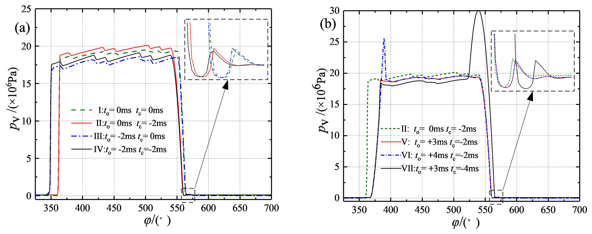
The plunger movement frequencies were chosen to be 15, 20, 25, and 30 Hz, the corresponding spindle speeds were 900, 1200, 1500, and 1800 r min−1, respectively, and the influences of different movement frequencies on the flow distribution characteristics of the pump were investigated, as shown in Fig. 10.
According to Fig. 10a and b, when the movement frequency increased from 15 to 20, 25, and 30 Hz, the liquid suction valve's opening lag angles were 16.00, 18.70, 20.69, and 21.85∘, respectively, resulting in liquid suction lag. The hysteresis angles were generated primarily by the residual pressure and the spring force in the plunger cavity, but the increase in frequency from 15 to 20, 25, and 30 Hz had less effect on the hysteresis of the closing of the suction valve, with hysteresis angles of 6.66, 7.90, 8.99, and 9.36∘, respectively. As the plunger movement frequency increased, the coordination between the suction valve's spool movement and the flow distribution during opening and closing was lacking. However, the high-speed switching valve's response time was fixed and did not change, which led to the closing of the drain valve in advance, at which the discharge valve began to close. Therefore, as the movement frequency increased, the increase in the corresponding suction valve's opening lag angle gradually decreased.
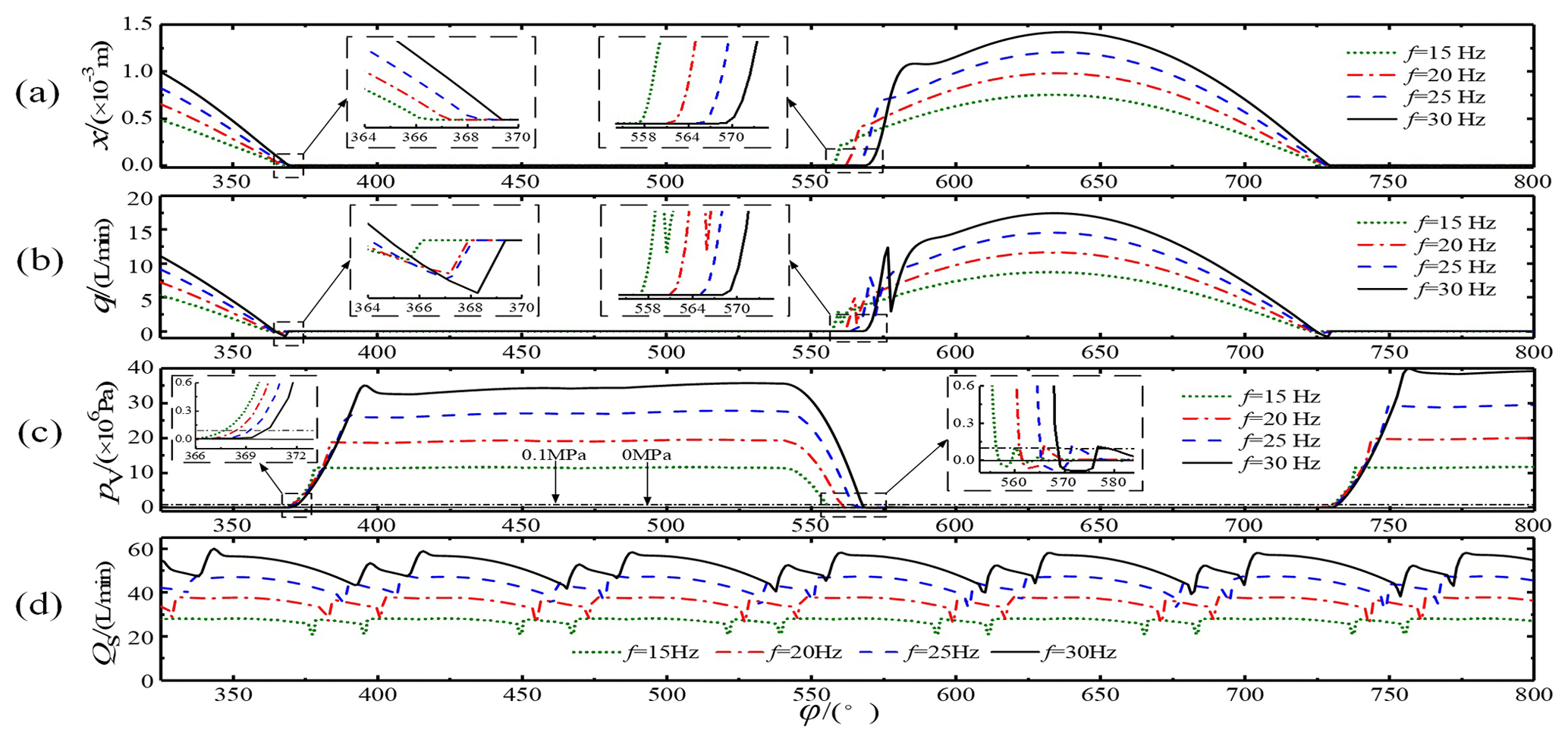
Figure 10Influence of different plunger movement frequencies: (a) spool displacement, (b) instantaneous flow in the suction valve, (c) pressure in the plunger chamber, and (d) total flow curve.
As shown in Fig. 10b, the instantaneous flow of the suction valve was inverted before closing, and the results of cause analysis are as follows. When the high-speed switching valve was opened, the plunger entered the oil discharge stroke. However, due to the lag in the closing of the suction valve, the backflow phenomenon occurred immediately before the closing of the suction valve. With an increase in the frequency, the plunger cavity's pressure during drainage also increased gradually; therefore, the breath flow also increased gradually, as shown in Fig. 10b.
In addition, as the plunger movement frequency increased, the pump flow increased, and the maximum opening displacement of the spool also increased. The suction valve spool's displacement vibration increased at the moment of opening, and the vibration of the spool further led to a drastic fluctuation in the flow curve, as shown in Fig. 10b and d.
At the end of drainage, the high-speed switching valve was closed early, coinciding with the critical position where the piston chamber changed from the discharge stroke to the suction stroke. Therefore, the pressure decreased synchronously at the end of the drainage stroke for all four frequencies. However, the high frequency corresponded to a higher pressure in the plunger chamber and a longer pressure relief time, and the pressure relief lag angle corresponded to the suction valve's opening lag angle. As shown in Fig. 10c, at the end of the discharge, as the plunger changed from a squeezing motion to a pumping motion, a negative pressure (relative to standard atmospheric pressure) was generated in the plunger chamber for a very short period of time. However, at this time, the high-speed switching valve had been actively closed, thereby significantly reducing the high-pressure liquid backflow phenomenon that exists in an ordinary valve distribution.
The hysteresis of the opening and closing of the suction valve was the primary factor governing the plunger movement frequency. The active opening and closing control of the discharge valve improved the flow distribution coordination and reduced the suction valve's hysteresis to a certain extent, thus improving the pump's volumetric efficiency and flow stability.
5.2 Influence of the dead zone's volume
The influence of the dead zone's volume on the pump distribution characteristics is shown in Fig. 11. When the dead zone's volume gradually increased from to , , and m3, its influence on the suction valve's closing lag angle was small, only 7.20∘; however, the opening lag angles were 12.23, 18.71, 23.03, and 26.63∘, respectively. The suction valve's opening lag angles increased with an increase in the dead zone's volume. However, the increase in amplitude gradually decreased, the oscillation amplitude at the spool's opening moment increased, and the spool's maximum opening displacement was not affected.
Figure 11b shows that with an increase in the dead zone's volume, the backward suction phenomenon remained essentially unchanged, during which the suction for the m3 volume ended earlier and the suction flow was slightly smaller. However, the overall flow curve changed significantly. The curve for the m3 volume showed a significant positive flow peak, while the curves for the and m3 volumes showed significant negative flow peaks, as shown in Fig. 11d.
This occurred because the plunger chamber's pressure began to rise when the plunger transferred from the suction stroke to the discharge stroke. As the pressure gradually rose, the suction valve was first forced to close; then, the control discharge valve was actively opened. During the time interval between the closing of the suction valve and the opening of the discharge valve, the plunger chamber's pressure rose further. The rate of the pressure increase was related to the size of the dead zone's volume. When this volume was small (such as m3), the pressure inside the chamber rose rapidly until it was much greater than the system's pressure outside the chamber. Then, the drain valve opened, instantly releasing the pressure and increasing the instantaneous supply of liquid to the system, which resulted in a positive flow spike, as shown in Fig. 11c and d. The pressure rose slowly when the dead zone's volume was large, and at the moment the dislocation valve opened, the pressure outside the cavity was greater than the pressure inside the cavity. This caused the flow to travel back into the plunger cavity, resulting in a negative flow spike. After the instantaneous reverse suction, due to the squeezing motion of the plunger, the plunger chamber's pressure increased to achieve normal discharge.

Figure 11Influence of different dead zone volumes: (a) spool displacement, (b) instantaneous flow in the suction valve, (c) pressure in the plunger chamber, and (d) total flow curve.
Figure 11c shows that with an increase in the plunger cavity's dead zone volume, the oil discharge pressure in the cavity decreased to a certain extent. There was little difference between the pressure relief time and the pressure construction time, and when the dead zone's volume gradually increased from to , , and m3, the pressure relief lag angles were 12.23, 19.05, 23.65, and 27.30∘, respectively. The primary reason for this phenomenon was that through a reasonable configuration of the drainage valve's opening and closing parameters (opening and closing strategy V), after the suction valve was delayed in closing, the opening of the discharge valve was immediately actively controlled; so, there was little difference in the construction pressure time. Because the discharge valve was actively closed early, when the pressure was relieved, the time interval between the closure of the discharge valve and the plunger's conversion from the discharge stroke to the suction stroke was long. A larger dead zone volume led to a slower pressure release, which eventually led to a gradual increase in the pressure relief time.
Figure 11 shows that when the dead zone's volume was m3, the positive and negative flow spikes were smaller, and the best flow stability was achieved. The trend in the influence of the calculated dead zone volume on the spool's displacement of the suction valve, the instantaneous flow at the suction valve port, and the plunger cavity pressure change were basically consistent with the research results of Zhu et al. (2018).
5.3 Influence of spring preloading
While keeping the other parameters unchanged, the suction valve core spring's preloading forces were chosen to be 0, 4, 8, and 12 N. The effects of these different preloading forces were analyzed, and the results are shown in Fig. 12.
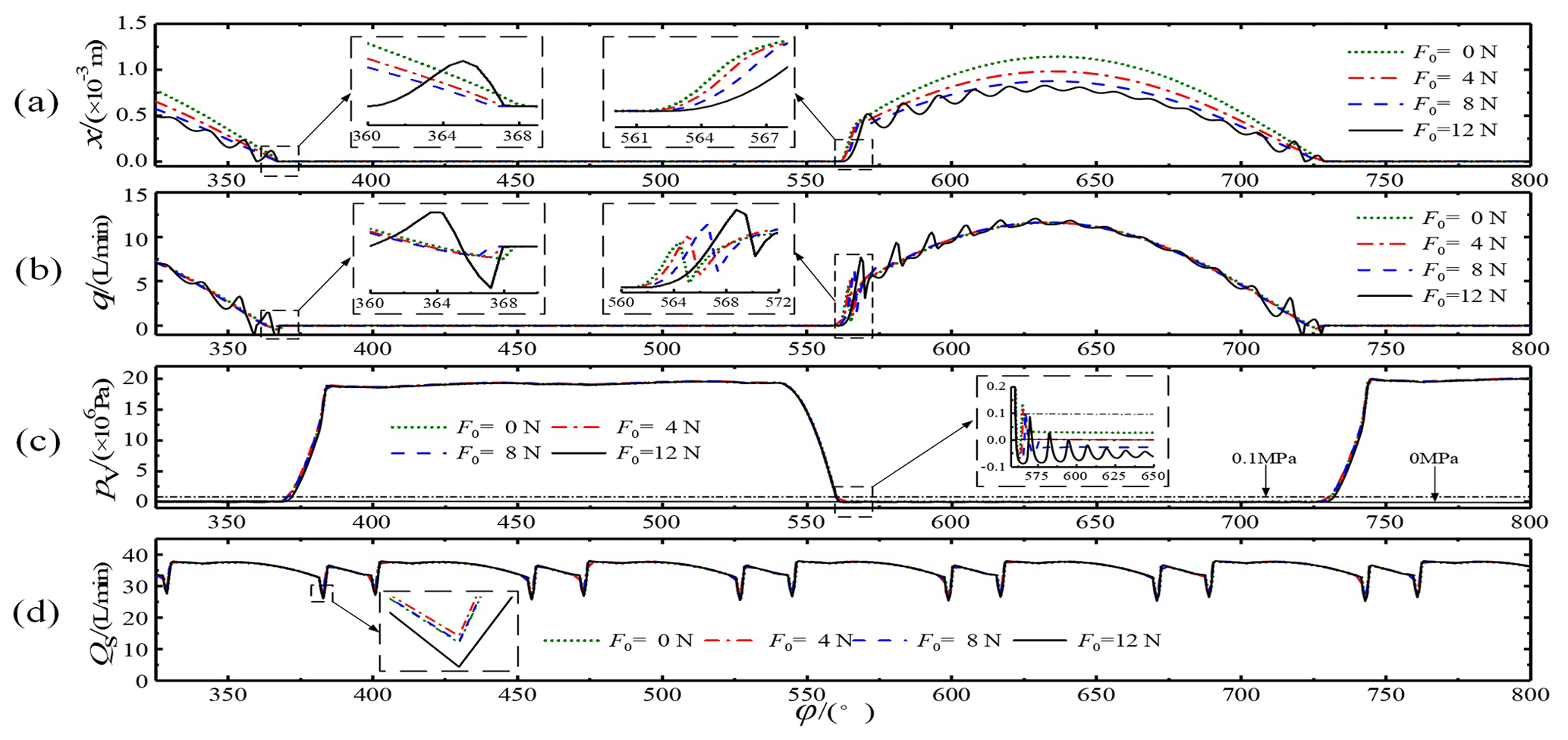
Figure 12Influence of different preloading forces: (a) spool displacement, (b) instantaneous flow in the suction valve, (c) pressure in the plunger chamber, and (d) total flow curve.
Figure 12a and b show that the smaller the preloading force was, the faster the suction valve opened and that the vibration of the valve core intensified with an increase in the preloading force. When the preloading force was 12 N, the valve core was difficult to open, causing oscillations and significant flow fluctuations. Generally, smaller preloading forces led to more difficulty in closing the suction valve, more obvious closing lag, and more serious flow suction. However, when the preloading force was 12 N, closing occurred early due to the non-stop oscillations of the spool, and the flow pulsation was larger. In addition, with a decrease in the preloading force, the spool's opening displacement gradually increased because an increase in the spool's displacement could produce a large enough spring force to contend with the liquid pressure.
Figure 12c shows that at the end of draining, the plunger chamber generated negative pressure within a very short period of time because the plunger transferred from a squeezing motion to a pumping motion. There were also slight differences in the plunger cavity's pressure patterns for different preloading forces. When the plunger cavity was sucking liquid, its pressure gradually decreased as the preloading force increased, and the suction pressure fluctuated significantly when the preloading force reached 12 N. This occurred because when the suction valve's inlet pressure was fixed and the preloading force was large, the plunger chamber needed a sufficiently large vacuum to overcome the spring preloading force and open the suction valve to absorb liquid.
Figure 12d shows the influence of the preloading force on the total flow pulsation. The flow peak was smaller when the preloading force was 4 N. This occurred because when there was no preloading force, although the force helped the spool to open the suction valve, there was a delay in closing of the spool, which intensified the suction. When the preloading force was too large, the amount of vacuum required for the spool to open increased, causing a delay in opening but an earlier closing of the spool. When the preloading force was 4 N, the spool opened earlier and closed earlier, resulting in better comprehensive performance and a higher volumetric efficiency. However, the effects of the preloading force on the total flow pulsation were not obvious.
The trend in the influence of the calculated spring preloading on the spool's displacement of the suction valve, the instantaneous flow at the suction valve port, the backflow phenomenon at the valve port, and the plunger cavity pressure were essentially consistent with the results of Qian et al. (2019).

Figure 13Influence of different equivalent masses of the spool: (a) spool displacement, (b) instantaneous flow in the suction valve, (c) pressure in the plunger chamber, and (d) total flow curve.
5.4 Influence of the spool's equivalent mass
While keeping the other parameters unchanged, the equivalent mass of the suction valve's spool was set to 0.5, 5, 10, and 15 g. The effects of these equivalent masses were analyzed, and the results are shown in Fig. 13.
Figure 13a and b show that smaller spool equivalent masses led to faster opening of the suction valve, but the flow rate fluctuated more quickly for smaller equivalent masses, and the amplitude of the fluctuation was small during the opening process. When the valve core's equivalent mass increased, the opening speed of the inlet valve decreased, the valve core's oscillation period increased, and the oscillation amplitude also increased. When the equivalent mass of the spool was 0.5 g, the suction valve's reverse effect was least obvious, while the other three masses produced slightly larger reverse effects that were very similar to each other.
Figure 13c shows that the pressure law in the plunger cavity remained essentially the same for the spool's different equivalent masses. At the end of the discharge, the plunger chamber generated negative pressure within a very short period of time because the plunger transferred from a squeezing motion to a suction motion. As the spool's equivalent mass increased, the negative pressure in the suction chamber gradually decreased, and its duration gradually increased. This occurred primarily because an increase in the spool's equivalent mass led to a significant increase in its inertia, requiring a greater vacuum to open the spool and causing the spool to open with a hysteresis tendency.
Figure 13d shows the effects of the spool's different equivalent masses on the total flow pulsation. The overall equivalent mass of the spool was small, and its effects on the total flow pulsation were not significant. In summary, the spool's equivalent mass should be minimized to reduce the effects of spool oscillation on the spring fatigue.
To study the flow characteristics of a balanced valve distribution double-row axial piston pump, relevant mathematical models were developed, the influences of structural parameters on the flow pulsation and uneven coefficient of flow were determined, the flow superposition process in the plunger cavity was analyzed, and the high-speed switching valve's control strategy was optimized. The results of this study can provide theoretical guidance for controlling the flow in balanced double-row axial piston pumps with valve distribution.
-
The balanced valve distribution double-row axial piston pump could effectively reduce the flow pulsation from that for a common single-row valve distribution piston pump. The number of inner and outer row plungers was equal, and the number of plungers (the same odd number or the same even number) increased the new pump's flow and decreased its pulsation. Overall, an odd number of plungers produced less pulsation than an even number. The smallest theoretical uneven coefficient of flow, δq, for a single row and an odd number of plungers occurred when the dislocation angle was . The smallest theoretical uneven coefficient of flow, δq, for a single row with an even number of plungers occurred when the dislocation angle was . The final solution took and θ=18∘, for which δq=1.24 %, and there was enough space for installation of the high-speed switching valve.
-
The hysteresis of the suction valve's opening and closing was the primary factor affecting the volumetric efficiency and the flow stability. The active opening and closing control of the discharge valve improved the coordination of the flow distribution to a large extent and reduced the suction valve's hysteresis, thus improving the pump's volumetric efficiency and flow stability. With the miniaturization of the high-speed switching valve, it could be used to replace the suction valve inside the plunger to achieve better flow control.
-
The plunger in the discharge valve's opening and the suction valve's critical closure caused an instantaneous backward suction effect, and the plunger cavity's dead zone volume size was the primary factor affecting the size of the pump's flow spike. The discharge valve's opening was delayed by 3 ms to be consistent with the suction valve's closing time. The flow peak was small for this case, and the volumetric efficiency was the highest. The discharge valve began to close 2 ms early and closed completely at the critical point when the plunger transferred from the discharge stroke to the suction stroke. This helped the suction valve to open on time and improved the pump's suction capacity.
-
An increase in the frequency of the plunger's movement aggravated the suction valve's opening and closing hysteresis and the valve port's reverse suction phenomenon. The dead zone's volume affected the plunger cavity's pressure building time, and volumes too large or too small were not suitable. To reduce the flow spikes, this volume should be considered to reasonably design the opening and closing timings for the suction and discharge valves. Spool preloading forces that are either too large or too small produced negative effects. To improve the volumetric efficiency, an appropriate preloading force caused the spool to open and close earlier. The spool's equivalent mass had minor effects on the flow characteristics, when the equivalent mass was small; however, considering the spring's fatigue damage, the spool's equivalent mass should be minimized.
All data included in this study are available upon request by contacting the corresponding author.
HT managed the overall conception and theoretical analyses for the paper. LZP built the AMESim simulation model and performed analyses. DHS derived the equations. CQM and ZKP conducted Matlab programming simulations. WCL analyzed the opening and closing control strategy of the high-speed switching valve.
The contact author has declared that neither they nor their co-authors have any competing interests.
Publisher’s note: Copernicus Publications remains neutral with regard to jurisdictional claims in published maps and institutional affiliations.
The authors wish to thank Anhui University of Science and Technology for its support. In addition, the authors wish to thank LetPub (https://www.letpub.com, last access: 11 January 2022) for its linguistic assistance during the preparation of this paper.
This study was financially supported by the National Natural Science Foundation of China (grant nos. 51575002 and 51675003), the Natural Science Foundation of Anhui Province (grant no. 2008085QE216), the Open Foundation of the Anhui Key Laboratory of Mine Intelligent Equipment and Technology (grant no. ZKSYS202101), the University Synergy Innovation Program of Anhui Province (grant no. GXXT-2019-048), and the Open Foundation of the State Key Laboratory of Fluid Power and Mechatronic Systems of China (grant no. GZKF-201715).
This paper was edited by Hui Ma and reviewed by two anonymous referees.
Ante, Š. and Nikola, V.: Numerical Determination of Volumetric Efficiency of High-Pressure Reciprocating Pumps, Brodogradnja, 60, 405–410, 2009.
Casoli, P., Pastori, M., Scolari, F., and Rundo, M.: Active Pressure Ripple Control in Axial Piston Pumps through High-Frequency Swash Plate Oscillations-A Theoretical Analysis, Energies, 12, 1377, https://doi.org/10.3390/en12071377, 2019.
Deng, H. S., Wang, Q. C., Wang, H. F., and Wang, C. L.: Relative motion relation in the external return spherical bearing pair of a balanced double-row axial piston pump, P. I. Mech Eng. C-J. Mec., 233, 3858–3872, https://doi.org/10.1177/0954406218805114, 2019.
Deng, H. S., Wang, C. L., and Zhang, L. X.: Study on flow ripple of balanced two-ring axial piston pump, Transactions of the Chinese Society for Agricultural Machinery, 45, 305–309, https://doi.org/10.6041/j.issn.1000-1298.2014.05.047, 2014.
Deng, H. S., Huang, K., Huang, R., Wang, C. L., and Deng, Y. F.: Swash plate moment property modelling and analysis of balanced two-ring axial piston pump, Chinese Journal of Engineering Design, 23, 592–599, https://doi.org/10.3785/j.issn.1006-754X.2016.06.011, 2016.
Deng, H. S., Hu, C., Wang, Q. C., Wang, L., and Wang, C. L.: Friction and wear analysis of the external return spherical bearing pair of axial piston pump/motor, Mechanics & Industry, 21, 104–117, https://doi.org/10.1051/meca/2019072, 2020.
Dong, P., Zhao, S. D., and Fan, S. Q.: Double-rotator and valve plate distribution radial piston pump, Assembly Autom., 40, 265–271, https://doi.org/10.1108/AA-12-2018-0270, 2019.
Guo, T., Zhao, S. D., Yu, Y. H. W., and Shang, P.: Design and theoretical analysis of a sliding valve distribution radial piston pump, J. Mech. Sci. Technol., 30, 327–335, https://doi.org/10.1007/s12206-015-1236-1, 2016.
Huang, J. H., Quan, L., and Zhang, X. G.: Development of a dual-acting axial piston pump for displacement-controlled system, P. I. Mech. Eng. B-J. Eng., 228, 606–616, https://doi.org/10.1177/0954405413506196, 2014.
Ivica, A., Ante, Š., and Zdravko, V.: Determination of Actual Discharge of High-Pressure Low-Discharge Axial Piston Pumps, T. FAMENA, 38, 1–10, 2014.
Jiang, J. H., Yang, K., Shen, T., Yang, G. W., Jiao, L., and Yang, A. R.: Flow ripple property of double row axial piston pump, Chinese Hydraulics & Pneumatics, 9, 28–32, https://doi.org/10.11832/j.issn.1000-4858.2017.09.006, 2017.
Lai, X. D., Ye, D. X., Chen, X. M., and Liao, Q.: Pressure pulsation behavior of a reactor coolant pump with mixed-flow diffuser and spherical casing, Journal of Chinese Society of Power Engineering, 40, 169–176, https://doi.org/10.19805/j.cnki.jcspe.2020.02.012, 2020.
Liu, Q. Y., Wen, D. S., and Gao, J. F.: Analysis on Balance Type Double-stator Axial Piston Pump and Its Flow Fluctuation, China Mechanical Engineering, 28, 228–232, https://doi.org/10.3969/j.issn.1004-132X.2017.02.016, 2017.
Luo, X. H., Niu, Z. H., Shi, Z. C., and Hu, J. H.: Analysis and design of an axial piston water-pump with piston valve, J. Mech. Sci. Technol., 25, 371–378, https://doi.org/10.1007/s12206-010-1214-6, 2011.
Ma, Y., Luo, H. S , Zhang, Z. H., Zhou, S. Q., and Deng, H. Y.: Numerical Modeling of Dynamic Characterics for Combined Valves in Multiphase Pump, Engineering Applications of Computational Fluid Dynamics, 11, 328–339, https://doi.org/10.1080/19942060.2017.1292409, 2017.
Manco, S., Nervegna, N., Lettini, A., and Gilardino, L.: Advances in the simulation of axial piston pumps, Proceedings of the 5th JFPS International Symposium on Fluid Power, Nara, Japan, 5, 251–258, https://doi.org/10.5739/isfp.2002.251, 2002.
Pan, Y., Li, Y. B., Huang, M. H., Ma, J., and Liang, D. D.: Valve Plate Improvement and Flow Ripple Characteristic Analysis for Double Compound Axial Piston Pump, Transactions of the Chinese Society for Agricultural Machinery, 47, 391–398, https://doi.org/10.6041/j.issn.1000-1298.2016.04.051, 2016.
Pedersen, N. H., Johansen, P., Hansen, A. H., and Andersen, T. O.: Model Predictive Control of Low-Speed Partial Stroke Operated Digital Displacement Pump Unit, Model. Ident. Control, 39, 167–177, https://doi.org/10.4173/mic.2018.3.3, 2018.
Qian, P. C., Ji, Z. Q., and Zhu, B. H.: Research on the dynamics and variable characteristics of a double-swash-plate hydraulic axial piston pump with port valves, J. Dyn. Syst.-T ASME, 141, 011006, https://doi.org/10.1115/1.4041012, 2019.
Roemer, D. B., Johansen, P., Pedersen, H. C., and Andersen, T. O.: Design and modeling of fast switching efficient seat Valve for digital displacement Pump, T. Can. Soc. Mech. Eng., 37, 71–87, https://doi.org/10.1139/tcsme-2013-0005, 2013.
Wang, D., Zhu, Y. Q., Li, Z. Y., and Zhang, T. H.: The development of plate type in seawater axial piston pump, Chinese Hydraulics & Pneumatics, 7, 29–32, https://doi.org/10.3969/j.issn.1000-4858.2001.07.013, 2001.
Wen, D. S., Sun, L. J., Xi, B., Du, F., Li, D. X., and Zhao, G. Q.: Output Torque Characteristics Analysis of Double Swash Plate Multi-row Axial Piston Motor, Transactions of the Chinese Society for Agricultural Machinery, 51, 420–426, https://doi.org/10.6041/j.issn.1000-1298.2020.06.046, 2020.
Xu, B., Hu, M., Zhang, J. H., and Su, Q.: Characteristics of volumetric losses and efficiency of axial piston pump with respect to displacement conditions, Journal of Zhejiang University Science A, 17, 186–201, https://doi.org/10.1631/jzus.a1500197, 2016.
Yan, B. Q.: Research on the piston pumps using high-speed on-off valve with phase shift of PWM control method, Fuzhou University, https://kns.cnki.net/kcms/detail/detail.aspx?FileName=1017051948.nh&DbName=CMFD2018 (last access: 10 January 2022), 2015.
Yan, L., Lian, Z. S., and Li, Y. K.: Dynamic characteristics and structure optimization of distribution valve for high-speed radial piston pump, Journal of Mechanical & Electrical Engineering, 37, 906–910, https://doi.org/10.3969/j.issn.1001-4551.2020.08.008, 2020.
Yang, H. Y., Wang, S., Zhang, B., Hong, H. C., and Zhong, Q.: Development and prospect of digital hydraulic valve and valve control system, Journal of Jilin University (Engineering and Technology Edition), 46, 1494–1505, https://doi.org/10.13229/j.cnki.jdxbgxb201605017, 2016.
Yu, J. T., Jiao, Z. X., and Wu, S.: Design, simulation and test of high-flow high-speed on/off valve driven by piezoelectric, J. Mech. Eng., 56, 226–234, https://doi.org/10.3901/JME.2020.18.226, 2020.
Zhang, B., Zhong, Q., Ma, J. E., Hong, H. C., Bao, H. M., Shi, Y., and Yang, H. Y.: Self-correcting PWM control for dynamic performance preservation in high speed on/off valve, Mechatronics, 55, 141–150, https://doi.org/10.1016/j.mechatronics.2018.09.001, 2018.
Zhang, J., Sun, H. Q., Dou, X. A., Kang, S. Q., and Kong, X. D.: Analysis of influencing factors on flow pulsation of inline type double row axial piston pump, Journal of Beijing Institute of Technology, 40, 481–485+490, https://doi.org/10.15918/j.tbit1001-0645.2018.436, 2020.
Zhang, X. G., Yan, Z., Quan, L., and Liu, Y. C.: Theoretical Analysis and Experiment on Flow Allocation Characteristics of Dual Discharging Axial Piston Pump, Chinese Society for Agricultural Machinery, 48, 373–380, https://doi.org/10.6041/j.issn.1000-1298.2017.06.049, 2017.
Zhang, Z. D., Yao, L. Y., Yao, L. H., Zhang, R. H., Li, Y. S., and Wang, C. S.: Theoretical study and simulation analysis of flow fluctuation of reciprocating-type positive displacement pump with multi plunger and check valve, Machine Tool & Hydraulics, 49, 128–135, https://doi.org/10.3969/j.issn.1001-3881.2021.02.028, 2021.
Zhao, S. D., Guo, T., Yu, Y. H. W., Dong, P., Liu, C., and Chen, W. Q.: Design and experimental studies of a novel double-row radial piston pump, P. I. Mech. Eng. C-J. Mec., 231, 1884–1896, https://doi.org/10.1177/0954406215623309, 2017.
Zhong, Q., Zhang, B., Bao, H. M., Hong, H. C., Ma, J. E., Ren, Y., Yang, H. Y., and Fung, R. F.: Analysis of pressure and flow compound control characteristics of an independent metering hydraulic system based on a two-level fuzzy controller, J. Zhejiang Univ.-Sc. A, 20, 184–200, https://doi.org/10.1631/jzus.A1800504, 2019.
Zhong, Q., He, X. J., Li, Y. B., Zhang, B., Yang, H. Y., and Chen, B.: Research on Control Algorithm for High-speed on/off Valves that Adaptive to Supply Pressure Changes, Chinese Mechanical Engineering Society, 57, 224–235, https://doi.org/10.3901/JME.2021.06.224, 2021a.
Zhong, Q., Xie, G., Wang, X. L., Li, Y. B., Yang, H. Y., Zhang, B., and Chen, B.: Performance Analysis of High Speed on/off Valve by Multi-voltages Compound Excitation, Chinese Mechanical Engineering Society, 57, 191–201, 2021b.
Zhu, B. H., Qian, P. C., and Ji, Z. Q.: Research on the flow distribution characteristics and variable principle of the double-swashplate hydraulic axial piston electric motor pump with port valves, J. Mech. Eng., 54, 220–234, https://doi.org/10.3901/JME.2018.20.220, 2018.
Zhu, G., Dong, S. M., Zhang, W. W., Zhang, J. J., and Zhang, C.: Variable stiffness spring reciprocating pump poppet valves and their dynamic characteristic simulation, China Mechanical Engineering, 29, 2912–2916, https://doi.org/10.3969/j.issn.1004-132X.2018.24.003, 2018.
- Abstract
- Introduction
- Working principle of the balanced valve distribution double-row axial piston pump
- Flow pulsation analysis
- Valve distribution model development and analysis of the flow distribution strategy
- Analysis of the valve distribution characteristics
- Conclusions
- Data availability
- Author contributions
- Competing interests
- Disclaimer
- Acknowledgements
- Financial support
- Review statement
- References