the Creative Commons Attribution 4.0 License.
the Creative Commons Attribution 4.0 License.
 | 01 Mar 2022
Simulation and analysis of a single actuated quadruped robot
Changtao Yan
Yanan Yao
In this paper, a leg structure of quadruped robot was designed, based on mechanism synthesis, and aims to allow a system for the complex control of a quadruped robot. This structure is composed of a crank linkage mechanism and quadrilateral mechanism. The innovativeness of this robot is that it can achieve a special gait driven only by single motor. In this research, we set up the kinematic model of leg mechanism through an analytic method. Then we draw the foot track of multiple groups of parameters and select the best parameter group by comparing multiple groups of parameters. After that, the robot model was built and analyzed for its walking ability and climbing ability with virtual prototype technology. Finally, we made an experimental prototype to trial the motion ability of the robot. Simulation and experimental analysis prove that the mechanism is reasonable, reliable and can meet the requirements of linear walking and climbing. The conclusions of this research will be useful for application in the field of single actuated quadruped robots.
- Article
(3722 KB) - Full-text XML
- BibTeX
- EndNote


With the progress of science and technology, the demand for cargo transportation and outdoor work on unstructured terrains is increasing, and more and more legged robots are emerging at than ever before (Ruan et al., 2020). Although the traditional wheeled and tracked robots have good stability and fast moving speed, they are greatly affected by terrain and a lack of obstacle surmounting ability (Liu et al., 2007). The legged robot has a strong ability to adapt to the environment and has its unique advantages in complex terrain such as mountains, steppes and bogs. Legged robots have been used more and more, especially when performing dangerous tasks (Chen et al., 2021; Biswal et al., 2021). Among the many types of legged robots, the quadruped robot is the most widely used in peoples' lives. A quadruped robot is mainly a robot system formed by imitating the skills of four-legged animals in nature or the skeletal structure and movement form of animals (Seok et al., 2015). Compared with a biped robot, a quadruped robot is more stable and has a stronger carrying capacity. Compared with hexapod and eight-legged robots, quadruped robots need to control fewer motors, and the control is more simple (Krishnamurthy, 2006). Therefore, in recent years, quadruped robots have been a hot topic in the field of robotics research (Cao et al., 2015). There are many representative products abroad, such as the quadruped mechanical horse first manufactured by Rygg (1983), which adopts the principle of a closed-chain linkage mechanism to realize high step frequency walking. A lizard quadruped robot called the water runner (Park et al., 2010) is composed of a quadruped linkage mechanism, which can run on water with high step frequency resistance. There is also BigDog, Spot mini and Cheetah by Boston Dynamics (Raibert et al., 2008; Katz et al., 2019), and ANYmal made by ETH Zurich (Hutter et al., 2017). Byeonghun and Kyoungchul (2016) designed a single degree of freedom quadruped robot, Cheetaroid-II, by analyzing the joint position at different times during a dog's movement, which can run faster on the treadmill. Park et al. (2014) and Kamidi et al. (2017) explored the single leg mechanism of a robot and proposed several fast-moving leg structures. The research of the quadruped robot in China is delayed compared to that in other countries, but with the efforts in recent years, fruitful results have been achieved. Ma et al. (1991) discussed some major problems in the movement and structural design of walking robots based on the combination of animal walking. There are some representative ones, such as Scalf-1 from Shandong University (Li et al., 2013) and the BIOS bot of Tsinghua University (Pouya et al., 2013; Sheba et al., 2016). From 2014 to 2016, X-dog, a quadruped robot, was designed and developed by Xingxing Wang at Shanghai University. Wu et al. (2019) combined four groups of quadruped robots into a 16-legged platform, which can perform turning and other functions through the interaction of four motors. Wu et al. (2017) analyzed the single leg structure by using the closed-vector method and optimized the parameters of the single leg structure. Then they studied a fully closed leg device and walking vehicle and produced the detailed design process of a single, closed-loop leg mechanism, a modular leg unit and a double quadruped robot (Wu and Yao, 2018a; Wu et al., 2021). Through the analysis and coupling of two single degree of freedom closed-chain structures, Wu et al. (2017) took the two closed-chain structures as walking platforms, which provides a new reference for the development of closed-chain leg platforms. Wei et al. (2022) proposed a passive leg mechanism and analyzed the critical conditions of the passive mechanism (Shafei and Shafei, 2018). In terms of application, Wu and Yao (2018b) proposed a quadruped bionic riding simulation vehicle, which can provide patients with equestrian auxiliary treatment, and has the dual function of transportation and treatment.
Based on the research results at home and abroad, a quadruped single drive robot is designed by using SOLIDWORKS modeling. The purpose is to design a quadruped platform that can carry certain items over a complex road surface. We optimized the leg structure and walking track of the quadruped robot, based on ADAMS virtual prototyping technology (Hao et al., 2020), and analyzed the plane motion ability and climbing ability of the robot.
2.1 Mechanism design
The research focuses on the following three goals: the reduction of the robot's actuators and sensors, the decrease in unnecessary energy consumption and the simplification of motion control.
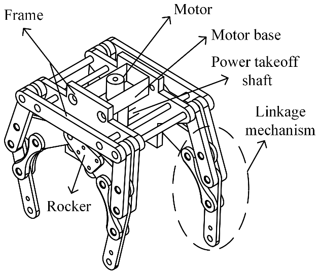
In order to reduce the complexity of control, this design only uses a single motor to drive the whole connecting rod system. And, compared with the articulated leg mechanism, we installed the drive motor directly on the motor base in order to reduce the mass and moment of inertia of the leg. The inner and outer feet of the quadruped robot have a phase difference in order to ensure the smooth walking of the quadruped robot. Based on the above analysis, the three-dimensional model of the designed single drive quadruped robot is shown in Fig. 1. Its length, width and height are 204, 180 and 239 mm, respectively.
2.2 The analysis of leg kinematics
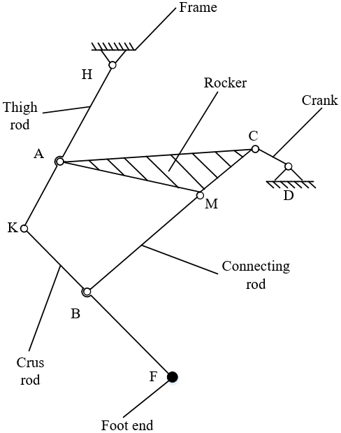
The leg motion mechanism of the quadruped robot designed in this paper is a multi-link motion mechanism, as shown in Fig. 2. The frame is fixed, the crank (DC), rocker (ACM) and thigh rod (HK) constitute the crank rocker mechanism, and the AMBK (see Fig. 2) quadrilateral structure constitutes the knee joint. The crank is driven by the motor to drive the thigh rod (HK) to move, and the crus rod (KF) moves under the joint action of the thigh rod (HK) and the connecting rod (BM) so that the foot end (F) forms a lifting and walking track with the leg (Long et al., 2018). The degree of freedom of the leg mechanism is as follows:
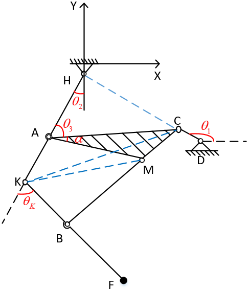
The coordinate system is established, as shown in the Fig. 3. When the crank position is known, according to the geometric relationship of the mechanism, the trajectory of point F at the foot end depends on the length of each connecting rod and the length of the crank. Suppose the lengths of rods DC, AC, AM, MC, AH, AK, BM, KB and BF are LDC, LAC, LAM, LMC, LAH, LAK, LBM, LKB and LBF, respectively, and the coordinates of point D are (LDx, LDy), then the angle between the crank and horizontal positive direction is θ1, the angle between AH and negative direction of y axis is θ2, ∠CAM=α, and the angle between KF and HK extension line is θK.
First, the position of the point C is as follows:
Since the three points, H, A and C, form triangles, the cosine law is applied to ΔHAC. θ2, θ3 can be calculated as follows:
|C| is the module of vector C. Cx is the x coordinate of C, and Cy is the y coordinate of C.
Then, the coordinates of point K and point A are as follows:
The cosine law is applied to ΔMAC. Thus, α can be calculated as follows:
The coordinates of point M are as follows:
In order to conveniently solve θK, KC and KM are connected, as shown in Fig. 3, as follows:
Finally, the coordinates of point F are as follows:
In this paper, the length of thigh rod, crus rod, crank and connecting rod has been determined, and then the track of the foot end is optimized by changing the length of AC, AM and MC. According to the trajectory of point F obtained in the previous section, the foot trajectory diagram was drawn with MATLAB, as shown in Fig. 4. As can be seen from Fig. 4, the foot end tracks of parameter groups 1, 2, 3 and 5 all have different degrees of forward or backward inclination. This will inevitably lead to the forward or backward deflection of the robot's center of gravity, thus affecting the stability of the robot motion. Therefore, we chose parameter group 4 for the experiment.


3.1 The analysis of plane walking function
According to the analysis of the above optimization results, we set the length of the thigh rod, crus rod, crank and connecting rod as 125, 106, 15 and 75 mm, respectively, and the rocker AC is equal to 100 mm, AM is equal to 31 mm, and MC is equal to 76 mm. In order to verify the motion performance of the robot, a robot model was established in SOLIDWORKS and imported into ADAMS, as shown in Fig. 6.
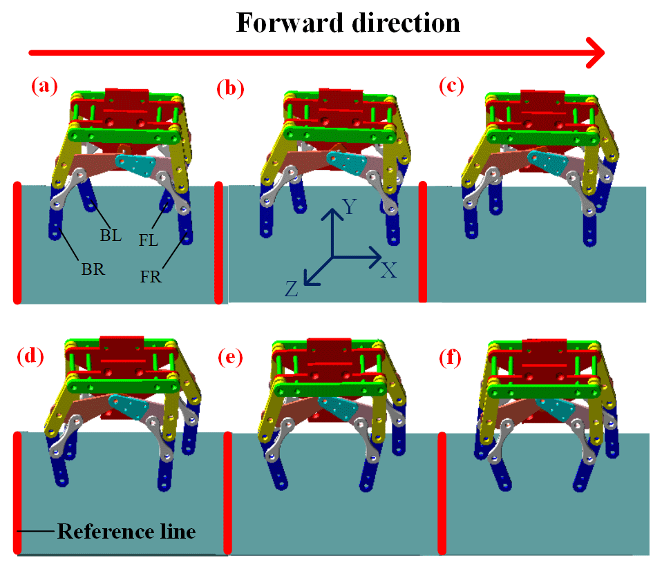
We then add constraints and define materials for each connecting rod in ADAMS. We add the drive to the spindle, set the drive function as 600D⋅ time and simulate for 5 s. The robot motion sequence is shown in Fig. 7. We set FL as the front left leg, FR as the front right leg, BL as the rear left leg and BR as the rear right leg in the forward direction. Figure 7, panel (a) is the initial state of the robot. In the forward state, the front left leg and the right hind leg form a diagonal angle, and the front right leg and the back left leg form another diagonal angle. The two diagonal legs move forward and backward in turn to realize the robot's forward and backward movement (as shown in Fig. 7, panels a–f).
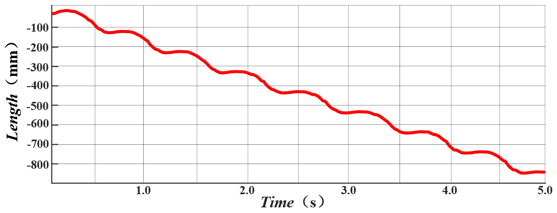
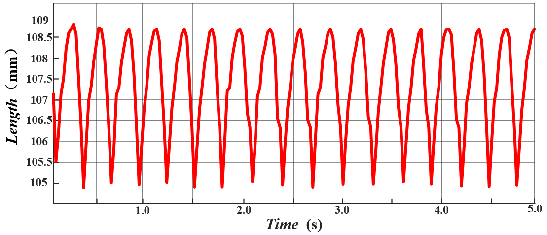
The step height and step length of the foot end were measured, and the measured results are shown in Figs. 8 and 9. As can be seen from Fig. 8, the leg lifting height of the leg mechanism is about 25 mm, and the step length is about 110 mm. In addition, the foot ends are periodic without obvious mutation, and the movement is relatively stable and uniform.

The centroid position, velocity and acceleration of the robot as a whole are analyzed below, as follows:
-
As shown in Fig. 10, the displacement of the centroid in the y direction during the stable movement of the robot is about 4 mm, which can prove that the walking state of the quadruped robot is relatively stable.
-
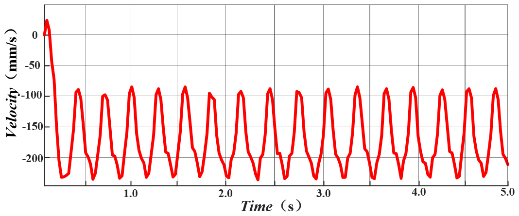
According to the joint analysis of Figs. 10 and 11, the robot has a minimum speed when the height of the robot's centroid reaches the highest point. The overall speed reaches its maximum in the middle of the return journey and decreases again when it reaches the ground. At this time, the other leg on the side starts to do the same movement until the movement returns to the first leg and the whole movement cycle ends. After the motion enters the stable state, the amplitude and frequency of speed fluctuation are basically the same, which proves that the robot motion is stable.
-
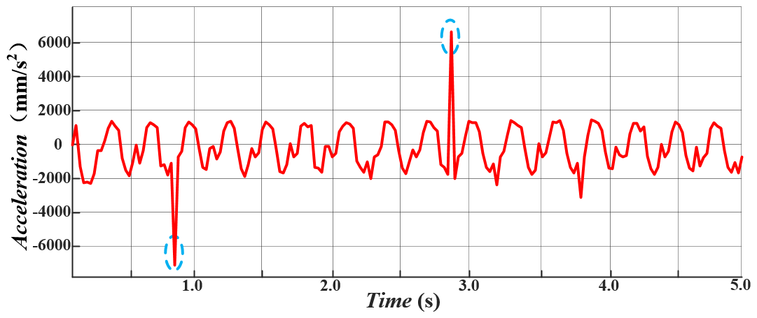
During the movement of the robot, there will be a sudden increase in acceleration (as shown in Fig. 12), which is caused by the quick return characteristics of the crank and rocker mechanism.
3.2 Analysis of climbing function
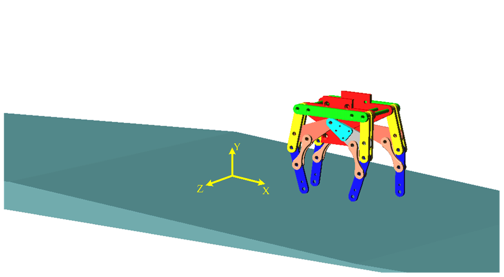
We simulate by the slope road in ADAMS for specifically analyzing the climbing ability of the robot, as shown in Fig. 13. Then we set the parameters in the software and select 10 s as a simulation cycle. The slopes of 4, 5, 6, 7 and 8∘ are selected for a comparative analysis, and the displacement change of the centroid on the y direction during climbing is obtained.
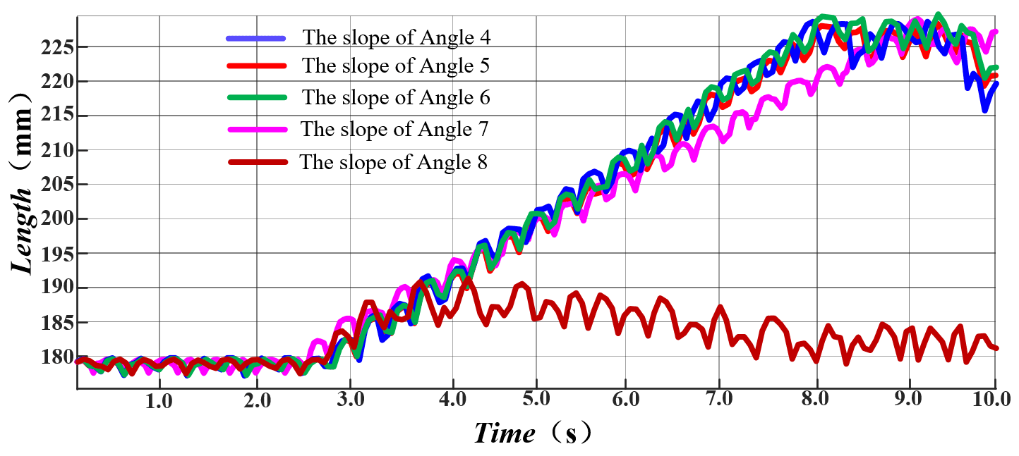
As shown in Fig. 14, when the robot moves at a slope of 7∘ and below, except for the shift of the centroid in the y direction caused by the increase of the height of the slope itself, then the shift in the centroid caused by the robot leg lifting movement is also relatively uniform. However, the shift of the centroid in the y direction cannot meet the shift of the centroid in the y direction caused by the increase in the height of the slope itself when the height is 8∘, indicating that the robot fails to go up the slope. Therefore, the robot is suitable for running on a slope of 7∘ or less. Next, we select the maximum slope that the robot can pass stably to study the displacement of the centroid along the x and z directions.
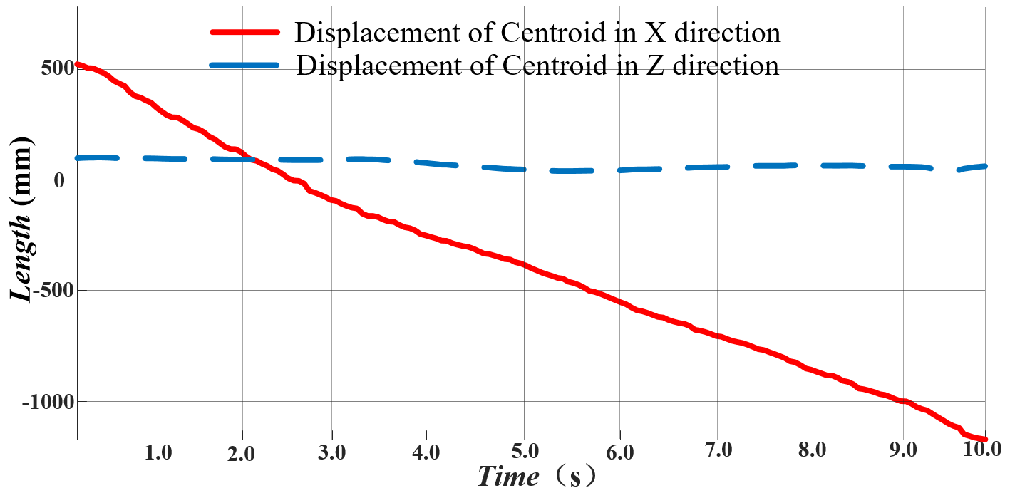
As shown in Fig. 15, the centroid deviation in the z direction is basically a straight line during the climbing movement of the robot, which proves that the robot has no deviation direction along the z direction. The displacement of the centroid along the x direction also has no mutation, which proves that the robot moves smoothly.
A micro experimental system composed of a gear motor, control unit, power supply, operation unit and walking system is built, as shown in Fig. 16.
The planar walking gait of the robot is demonstrated in Fig. 17, which proves that the quadruped robot can walk well on the flat ground.
Figure 18 shows that the robot can easily cross a 15 mm obstacle. In addition, it also shows that the robot can remain stable when one leg crosses a 20 mm obstacle.
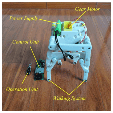
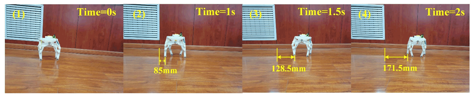

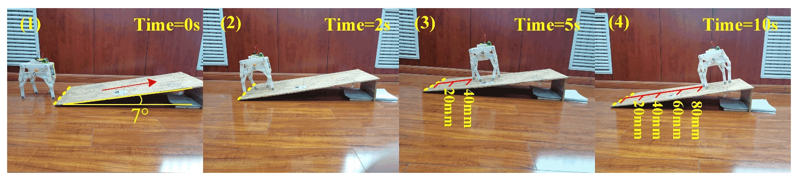
Figure 19 illustrates the climbing ability of the robot. At this point, the slope is 7∘.

The ability to respond to the environment is verified by the experiment shown in Fig. 20. This figure shows the operation of the robot on rough roads and downhill roads, respectively (Φ is the angle at which the crank is turned, and α is the downhill slope).
Aiming at the complex problem of the multi-motor control of a quadruped robot, we proposed a leg structure scheme of single degree of freedom linkage quadruped robot. The leg mechanism, driven by single motor, was designed by using a crank connecting a rod mechanism and quadrilateral structure. The expression of the sitting mark of the foot end and the dimensions of each connecting rod are determined by kinematic analysis, using SOLIDWORKS to establish a 3D model which is then imported into ADAMS. The walking and climbing abilities of the robot are analyzed by an experiment and virtual prototype technology. The structure of this design has the following advantages:
-
The designed mechanical leg structure is combined with bionics and analyzed by virtual prototype technology.
-
The structure adopts a pure mechanism, multi-connecting rod and single motor, which has the advantages of simple control, a reliable motion system and good linear walking ability.
-
This robot has a good ability to adapt to a complex environment and provide a certain reference for the future single-motor-driven connecting rod robot.
All the data used in this article can be made available upon reasonable request. Please contact the first author (changtao.yan@hotmail.com).
KS and YY proposed and developed the overall concept of the paper and conducted the mechanism design and analysis. CY and HZ wrote the whole paper.
The contact author has declared that neither they nor their co-authors have any competing interests.
Publisher's note: Copernicus Publications remains neutral with regard to jurisdictional claims in published maps and institutional affiliations.
The authors would like to acknowledge the financial support from the Foundation of Key Laboratory of Vehicle Advanced Manufacturing, Measuring and Control Technology (Beijing Jiaotong University), Ministry of Education, China, and Shanghai Collaborative Innovation Center of Intelligent Manufacturing Robot Technology for Large Components (grant no. ZXP20211101).
This work has been supported by Foundation of Key Laboratory of Vehicle Advanced Manufacturing, Measuring and Control Technology (Beijing Jiaotong University), Ministry of Education, China and Shanghai Collaborative Innovation Center of Intelligent Manufacturing Robot Technology for Large Components (grant no. ZXP20211101).
This paper was edited by Guimin Chen and reviewed by two anonymous referees.
Biswal, P. and Mohanty, P. K.: Development of quadruped walking robots: A review, Ain Shams Engineering Journal, 12, 2017–2031, https://doi.org/10.1016/j.asej.2020.11.005, 2021.
Byeonghun, N. and Kyoungchul, K.: Design of a One Degree-of-Freedom Quadruped Robot Based on a Mechanical Link System: Cheetaroid-II, J. IFAC Papers online, 49, 409–415, https://doi.org/10.1016/j.ifacol.2016.10.589, 2016.
Cao, J. Q., Li, B., and Yuan, W. F.: Design and Analysis of Quadruped Single Drive Mechanical Horse Mechanism, Machinery Design and Manufacture, 4, 228–232, https://doi.org/10.19356/j.cnki.1001-3997.2015.04.062, 2015.
Chen, J. P., San, H. J., Wu, X., and Xiong, B. Z.: Structural design and gait research of a new bionic quadruped robot, P. I. Mech. Eng. B-J. Eng., https://doi.org/10.1177/0954405421995663, online first, 2021.
Hao, Y. L., Tian, Y. B., Wu, J. X., Li, Y. Z., and Yao, Y. A.: Design and locomotion analysis of two kinds of rolling expandable mobile linkages with a single degree of freedom, Frontiers of Mechanical Engineering, 15, 365–373, https://doi.org/10.1007/s11465-020-0585-3, 2020.
Hutter, M., Gehring, C., Lauber, A., Gunther, F., Bellicoso, C. D., Tsounis, V., Fankhauser, P., Diethelm, R., Bachmann, S., Bloesch, M., Kolvenbach, H., Bjelonic, M., Isler, L., and Meyer, K.: ANYmal – toward legged robots for harsh environments, J. Adv. Robot., 31, 918–931, https://doi.org/10.1080/01691864.2017.1378591, 2017.
Kamidi, V. R., Saab, W., and Ben-Tzvi, P.: Design and analysis of a novel planar robotic leg for high-speed locomotion, 2017 IEEE/RSJ International Conference on Intelligent Robots and Systems (IROS) IEEE, 24 to 28 September 2017, Vancouver, Canada, https://doi.org/10.1109/IROS.2017.8206540, 2017.
Katz, B., Carlo, J. D., and Kim, S.: Mini cheetah: A platform for pushing the limits of dynamic quadruped control (Conference Paper), IEEE Int. Conf. Robot., 2019, 6295–6301, https://doi.org/10.1109/ICRA.2019.8793865, 2019.
Krishnamurthy, V. R.: Intuitive Design and Gait Analysis for a Closed Loop Leg Mechanism of a Quadruped with Single Actuator, Climbing and Walking Robots – Proceedings of the 8th International Conference on Climbing and Walking Robots and the Support Technologies for Mobile Machines, CLAWAR 2005, London, UK, 13–15 September 2005, 303–310, https://doi.org/10.1007/3-540-26415-9_36, 2006.
Li, B., Li, Y. B., Rong, X. W., Meng, J., and Chai, H.: The Effects of Leg Configurations on Trotting Quadruped Robot, Proceedings of 2013 Chinese Intelligent Automation Conference: Intelligent Automation & Intelligent Technology and Systems, 255, 365–374, https://doi.org/10.1007/978-3-642-38460-8_41, 2013.
Liu, J., Tan, M., and Zhao, X. G.: Legged robots – an overview, J. T. I. Meas. Contr., 29, 185–202, 2007.
Long, B., Long, Z., and Chen, X. H.: Design and Analysis of a Leg Mechanism for a Continuous Electrically-Driven Quadruped Robot, Robot., 40, 136–145, https://doi.org/10.13973/j.cnki.robot.170443, 2018.
Ma, P. S., Lu, S. S., and He, Q. W.: Motion and Structure Design of Quadruped Walking Robot, Machine Design and Research, 4, 34–39, https://doi.org/10.13952/j.cnki.jofmdr.1991.04.008, 1991.
Park, H. S., Floyd, S., and Sitti, M.: Roll and Pitch Motion Analysis of a Biologically Inspired Quadruped Water Runner Robot, Int. J. Robot. Res., 29, 1281–1297, https://doi.org/10.1177/0278364909354391, 2010.
Park, J., Kim, K. S., and Kim, S.: Design of a cat-inspired robotic leg for fast running, J. Adv. Robot., 28, 1587–1598, https://doi.org/10.1080/01691864.2014.968617, 2014.
Pouya, S., Eckert, P., Sproewitz, A., Moeckel, R., and Ijspeert, A.: Motor Control Adaptation to Changes in Robot Body Dynamics for a Complaint Quadruped Robot, Biomimetic and Biohybrid Systems, 8064, 434–437, https://doi.org/10.1007/978-3-642-39802-5_58, 2013.
Raibert, M., Blankespoor, K., Nelson, G., and Playter, R.: BigDog, the Rough-Terrain Quadruped Robot, IFAC Proceedings Volumes, 41, 10822–10825, https://doi.org/10.3182/20080706-5-KR-1001.01833, 2008.
Ruan, Q., Yao, Y. A., and Wu, J.: Analysis and experiments on a novel smoothly moving low-DOF multilegged-robot, P. I. Mech. Eng. C-J. Mec., 234, 302–317, https://doi.org/10.1177/0954406219848468, 2020.
Rygg, L. A.: Mechanical horse: US, P. US491927 A, 1983.
Seok, S., Wang, A., Michael, C., and Meng, Y.: Design principles for energy-efficient legged locomotion and implementation on the MIT Cheetah robot, J. IEEE-ASME T. Mech., 20, 1117–1129, https://doi.org/10.1109/TMECH.2014.2339013, 2015.
Shafei, A. M. and Shafei, H. R.: Dynamic modeling of planar closed-chain robotic manipulators in flight and impact phases, Mech. Mach. Theory, 126, 141–154, https://doi.org/10.1016/j.mechmachtheory.2018.03.007, 2018.
Sheba, J. K., Elara, M. R., Martínez-García, E., and Tan-Phuc, L.: Trajectory Generation and Stability Analysis for Reconfigurable Klann Mechanism Based Walking Robot, Robotics, 5, 13, https://doi.org/10.3390/robotics5030013, 2016.
Wei, C. R., Sun, H. Z., Liu, R., Yao, Y. A., Wu, J. X., Liu, Y., and Lu, Y. X.: Analysis and experiment of thrust-propelled closed-chain legged platform with passive locomotion ability, Mech. Mach. Theory., 167, 104506, https://doi.org/10.1016/j.mechmachtheory.2021.104506, 2022.
Wu, J. X. and Yao, Y. A.: Design and analysis of a novel walking vehicle based on leg mechanism with variable topologies, Mech. Mach. Theory, 128, 663–681, https://doi.org/10.1016/j.mechmachtheory.2018.07.008, 2018a.
Wu, J. X. and Yao, Y. A.: Design and analysis of a novel multi-legged horse-riding simulation vehicle for equine-assisted therapy, P. I. Mech. Eng. C-J. Mec., 232, 2912–2925, https://doi.org/10.1177/0954406217728300, 2018b.
Wu, J. X., Yao, Y. A., Ruan, Q., and Liu, X. P.: Design and optimization of a dual quadruped vehicle based on whole close-chain mechanism, P. I. Mech. Eng. C-J. Mec., 231, 3601–3613, https://doi.org/10.1177/0954406216650473, 2017.
Wu, J. X., Yao, Y. A., and Li, Y. B.: Design and Analysis of a Sixteen-Legged Vehicle with Reconfigurable Close-Chain Leg Mechanisms, J. Mech. Robot., 11, 055001, https://doi.org/10.1115/1.4044003, 2019.
Wu, J. X., Yang, H. B., Li, R. M., Ruan, Q., Yan, S., and Yao, Y. A.: Design and analysis of a novel octopod platform with a reconfigurable trunk(Article), Mech. Mach. Theory, 156, 104134, https://doi.org/10.1016/j.mechmachtheory.2020.104134, 2021.