the Creative Commons Attribution 4.0 License.
the Creative Commons Attribution 4.0 License.
 | 19 Dec 2022
Dynamic modeling and vibration characteristics analysis of parallel antenna
Guoxing Zhang
Jianliang He
Jinwei Guo
Xinlu Xia
Research on the vibration characteristics of the mechanical systems is a necessary step for the stable and reliable operation of high-end equipment. The 6 degrees of freedom parallel mechanism is proposed for the supporting mechanism of the antenna. First, the dynamic equations of the moving platform and branch of the mechanism are established. The closed-form dynamics of the mechanism are derived based on the Newton–Euler method. In addition, the vibration equation of the parallel antenna is established based on the vibration theory, and the relationship between the natural frequency, displacement response, and vibration frequency is obtained. Afterward, the pitch and roll poses of a 1.8 m aperture antenna are developed based on a MATLAB software simulation. The actuation forces of parallel antenna under no-load and load conditions are simulated. Finally, the natural frequencies and vibration modes of the initial position and roll (20∘) are simulated based on the Adams software vibration analysis module. Furthermore, the relationship between the displacement response of the moving platform and the resonant frequency is studied based on the harmonic response analysis. The control strategy based on the dynamic model improves the control accuracy of parallel antenna. This research work provides a guarantee for the dynamic characteristics analysis and engineering application of parallel antenna.
- Article
(9967 KB) - Full-text XML
-
Supplement
(1446 KB) - BibTeX
- EndNote


Compared with the series mechanism, the parallel mechanism contains multiple legs and a closed chain structure. With the characteristics of a compact structure, excellent bearing performance, low motion inertia, and small error accumulation (Huang et al., 2013), the parallel mechanism is widely used in motion simulators, shaking tables, space-docking mechanisms, satellite antennas, and other fields (Furqan et al., 2017). The Stewart mechanism is the most classic of the parallel mechanisms and contains a fixed platform, a moving platform, and six actuation branches connecting the fixed and moving platforms. The 6 degrees of freedom (DOF) parallel mechanism was first applied as a flight simulator (Stewart, 1965). A wave compensation platform (Zhan et al., 2020), based on a 3-SPR (where S is the spherical joint, P is the prismatic joint, and R is the revolute joint) parallel platform, is designed for marine ships with a dynamic positioning system. A 3-CPU (where C is the cylindrical joint, P is the prismatic joint, and U is the universal joint; Corinaldi et al., 2017) parallel pointing mechanism for a singularity-free path planning problem is studied. Based on the modular design concept, a new truss antenna mechanism is proposed (Guo et al., 2020), and the expansion rate performance is compared and analyzed. The rigid–flexible coupled dynamic modeling and dynamic characterization of the 4SRS+SS parallel tracking mechanism are investigated (Zhang et al., 2020). A parallel pointing mechanism for solar tracking is designed (Altuzarra et al., 2015). The synthesis of parallel antenna mechanisms based on displacement subgroups and displacement manifolds is investigated, and two new parallel antenna mechanisms with two rotational DOF are proposed (Song et al., 2016). The stiffness performance of a novel 2 DOF fast-pointing static mechanism is investigated (Abid et al., 2020). A URU-RR-URU module antenna is synthesized by connecting the mechanism configuration, and the influence of spring stiffness on the antenna is analyzed (Guo et al., 2022). A new direct measurement method is proposed to achieve high-accuracy cylinder friction tests (Qian et al., 2022). The mechanical analysis of a deployable antenna based on the 3RR-3URU element is carried out (Guo et al., 2022).
Dynamic models can improve the response velocity and accuracy of parallel mechanisms. In the design of a dynamic control scheme, it is often necessary to obtain the display form of the dynamic model. The kinematics and dynamics of the 6-SPS (where S is the spherical joint and P is the prismatic joint) parallel mechanism were modeled based on the Kane method (Wu et al., 2012). The closed-form dynamic model of the Stewart mechanism is obtained using the Kane method (Asadi et al., 2018). The dynamics and motion characteristics of a 4 DOF hybrid antenna mechanism are analyzed (Zhang et al., 2021). The dynamics of a 6 DOF micro-vibration simulator are modeled by the Kane method, and dynamic joint simulations are performed (Yang et al., 2016). A general method for the improved dynamic modeling of the Stewart platform based on the virtual working principle is proposed (Kalani et al., 2016). The dynamics model of a parallel mechanism with flexible hinges is developed based on the principle of virtual work (Jiao et al., 2019). The PU-2UPS 3 DOF parallel antenna is proposed, and the dynamics of the mechanism is analyzed (Zhang et al., 2021). The inverse dynamics model of the series–parallel dynamics simulator, based on the principle of virtual work and the kinematic model, is investigated (Hu et al., 2016). By applying a combination of the Lagrangian formulation and the Newton–Euler method, explicit compact, closed-form dynamic equations are presented (Guo et al., 2006). The improved Stewart parallel manipulator dynamic equations are generated using the Newton–Euler method, considering the rotational DOF of the pod around the axial direction (Pedrammehr et al., 2012). A systematic approach is proposed to solve the inverse dynamics of the Stewart–Gough manipulator utilizing the virtual work principle (Tsal et al., 2000). The kinetic equations of the 6–6 Stewart mechanism were established using the principle of virtual work, and the steps of establishing the kinetic model were summarized and verified using the Lagrangian method (Staicu, 2011). The representation of the screw velocity and acceleration in the object coordinate system and the spatial coordinate system is given, the Hessian matrix of the parallel mechanism is derived by combining the principle of virtual work, and the dynamics model is established (Zhao, 2015). The parameter optimization of the 6 DOF parallel vibration isolated platform is investigated (Cheng, 2019). A dynamic and vibration analysis of seismically isolated platforms based on displacement and force characteristics is carried out (Chen, 2021). A novel method for analyzing the natural frequencies of parallel robots is proposed, which focuses on the lowest natural frequencies and expresses the corresponding natural modes in the Cartesian reference system of the end-effector (Hoevenaars, 2019). The dynamic performance of the Stewart mechanism is evaluated by natural frequencies and local dynamic anisotropy indices (Bang, 2014).
Due to the complex kinematic chain structure of parallel mechanisms, its dynamic model often presents the characteristics of many coupling parameters and strong nonlinearity. Currently, the research on parallel antennas mainly focuses on configuration design and dynamic modeling. There are few reports on the vibration characteristics and harmonic response analysis combined with the specific working conditions of parallel antenna. The working environment of the antenna system is often inadequate and vulnerable to external interference. The research on vibration characteristics is a vital link for the stable and reliable operation of parallel antennas. Considering the practical working requirements of a 6 DOF antenna system, this paper establishes the closed dynamic model of the mechanism, simulates the motion and attitude of the parallel antenna, and carries out the modal and harmonic response analysis of the parallel antenna.
2.1 Dynamic equation of moving platform
Considering the pitching and azimuth motion requirements of an antenna, the self-weight of the antenna reflector, and the influence of wind load, a 6 DOF parallel mechanism is adopted to support the position antenna. The structural diagram of the parallel antenna support mechanism is shown in Fig. 1a. The force relationship of each component of the parallel antenna under the condition of ignoring the mass and inertia of Hooke hinge is shown in Fig. 1b. represents the position of the hooker joint of the fixed platform. represents the position of the spherical joint of the moving platform. represents the position of the moving joint.
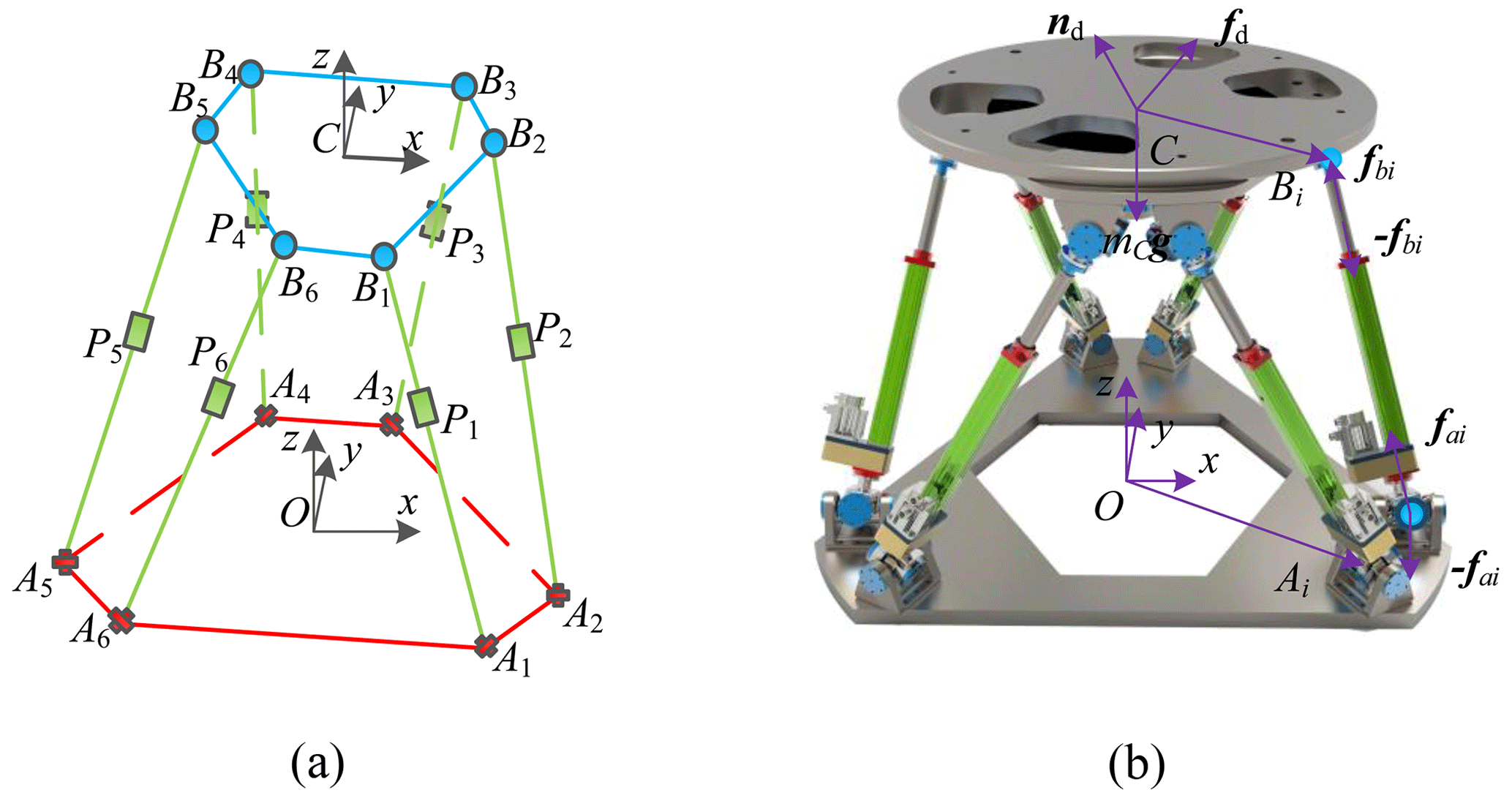
Figure 1Force diagram of the parallel antenna. (a) Schematic diagram of parallel antenna. (b) Force diagram of parallel antenna.
Assuming that the centroid of the moving platform is located at the center point C. The mass of the moving platform is represented by mC. The moment of inertia relative to the reference coordinate system O−xyz is represented by OIC. The dynamic platform is subjected to the force of the six branches, while considering the gravitational force on the dynamic platform itself and the external disturbance force that may act on the dynamic platform. The dynamic platform force is shown in Fig. 1. The Newton–Euler method is used to write the equilibrium equation of the moving platform of the parallel antenna.
The relationship of rotational inertia migration can be expressed by the following equation:
According to Eq. (2), the expressions of FC, MC, CC and GC are further obtained as follows:
Establishing the explicit dynamic equations of each component is the basis for establishing the explicit dynamic equations of the mechanism as a whole. The general form of the dynamic equations of the moving platform of the parallel antenna can be expressed as follows:
where X represents the six-dimensional vector of the position and attitude of the moving platform, i.e., .
According to the differential equations for the linear and angular velocities of the rigid body, is obtained. According to the differential equation of linear and angular acceleration of the rigid body, is obtained.
2.2 Dynamic equations of branches
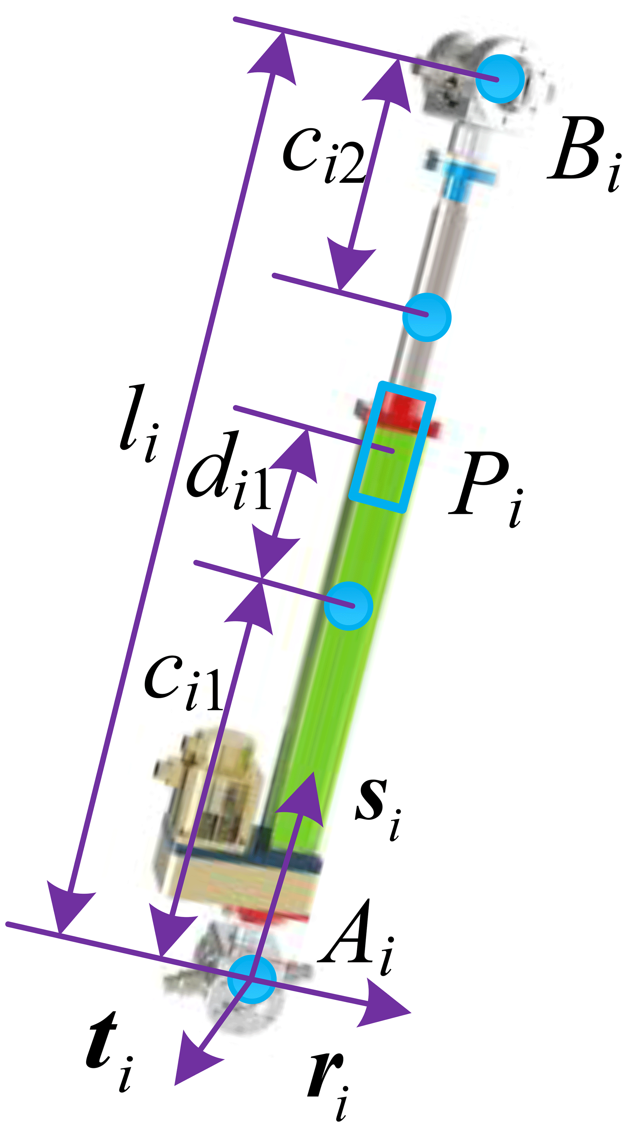
Each branch of the 6 DOF antenna mechanism consists of two parts, i.e., the actuation link AiPi and the actuation link PiBi, as shown in Fig. 2. The centroid of the actuation link AiPi is at a distance ci1 from the hinge point Ai of the fixed platform. The centroid of the actuation link PiBi is at a distance ci2 from the hinge point Bi of the moving platform. The distance from the centroid of the actuation link AiPi to the force point of the actuation link is di1. The distance between the fixed platform hinge point and the moving platform hinge point of the parallel antenna is represented by li.
The force relationship of the actuation link PiBi of the 6 DOF antenna mechanism is shown in Fig. 3. The actuation link PiBi is subjected to the force fai applied by the fixed platform at the hinge point Bi. The reaction force −fpi and torque −Mpi are applied by the actuation link PiBi at the point and the gravity mi2g received by the actuation link.
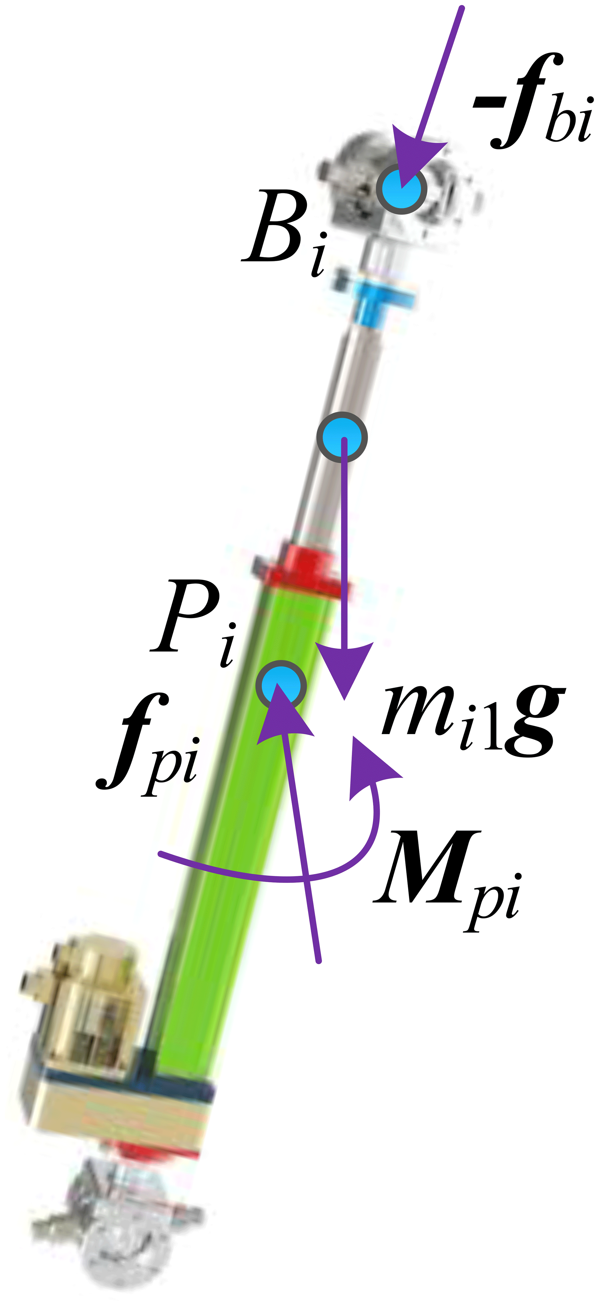
According to the force relationship of the actuation link PiBi, the balance equation of the actuation link PiBi of the parallel antenna is written by Newton–Euler method as follow:
According to the transfer relationship of moment of inertia, OICi1 can be expressed by the following formula:
The force relationship of actuation link AiPi of the parallel antenna is shown in Fig. 4. The actuation link AiPi is subjected to the reaction force −fbi applied by the moving platform at the hinge point Ai. The force fpi and torque Mpi are applied by the actuation link PiBi at point Pi and the gravity mi1g on the actuation link itself.
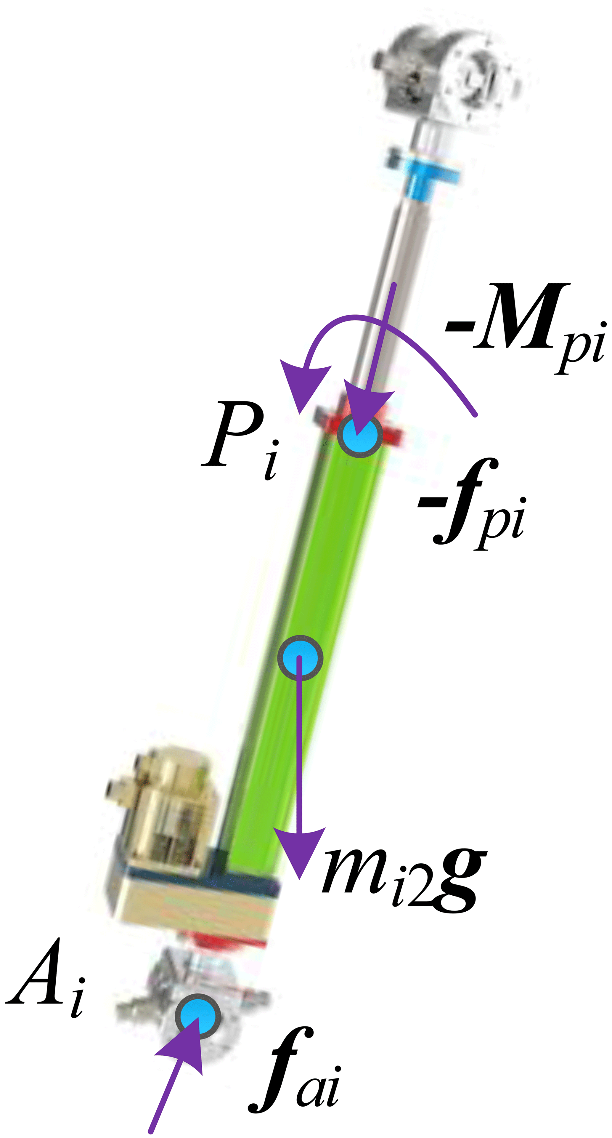
According to the force relationship of the actuation link AiPi, the balance equation of the actuation link AiPi is written by Newton–Euler method as follows:
According to the transfer relationship of moment of inertia, OICi2 can be expressed by the following formula:
The expressions of Fpi, Mpi, Cpi, and Gpi can be obtained as follows, according to Eq. (8):
The general form of the dynamic equation of each branch component of the parallel antenna can be expressed as follows:
where x represents the six-dimensional vector of the position and attitude of the moving platform, i.e., .
According to the differential formula of the linear velocity and angular velocity of the rigid body, is obtained, and according to the differential formula of the linear acceleration and angular acceleration of the rigid body, is obtained.
2.3 Closed-form dynamic model
To obtain the closed-form dynamic model of the parallel antenna, it is necessary to integrate the dynamic models of the moving platform and each branch, complete the transformation of the intermediate generalized coordinates and the main generalized coordinates through coordinate transformation, and consider the force relationship between the moving platform and each branch.
Calculate the relationship based on the parallel mechanism velocity Jacobian as follows:
Then solve differential Eq. (11) to obtain the following:
Next, substitute Eq. (12) into Eq. (10) and multiply both sides of the equation by JT to obtain the following:
The expressions of Fi, Mi, Ci, and Gi can be obtained, according to Eq. (13):
Therefore, Eq. (13) can be expressed as follows:
Combined with the dynamic expression (Eq. 4) of the moving platform of the parallel antenna and the dynamic expression (Eq. 10) of each branch, the closed-form dynamic equation expression of the parallel antenna is as follows:
where
2.4 Theoretical analysis of vibration systems
Combined with the relevant knowledge of vibration theory, the dynamic model of the parallel antenna described in Eq. (16) can be sorted into the form of a motion differential equation, as follows:
where M represents the mass matrix, C represents the damping matrix, and K represents the stiffness matrix.
Since the damping does not have an effect on the natural frequency and vibration mode of the system, the undamped free vibration equation of the system is sorted out as follows:
The characteristic equation of the system can be expressed as follows:
The natural frequency ω0 of the parallel antenna system can be obtained by solving Eq. (19).
The basic dynamic equation of the harmonic response analysis of the parallel antenna is expressed as follows:
where Fe is the excitation force, ω1 is the excitation frequency of forced vibration, and φ is the phase angle.
The formula (Eq. 20) can be obtained in the parallel antenna without damping the simple harmonic excitation of the structure amplitude and frequency response relationship.
3.1 Motion posture simulation
When considering the actual working requirements of a 1.8 m aperture antenna system, it is necessary to realize the ±20∘ roll motion and ±20∘ pitch motion around the coordinate axis, and roll–pitch–yaw angles are used to describe the motion attitude of the parallel antenna. The position matrix of the center of the moving platform is expressed as follows:
The three motion forms of the parallel antenna obtained through the analytical solution of MATLAB are shown in Fig. 5.
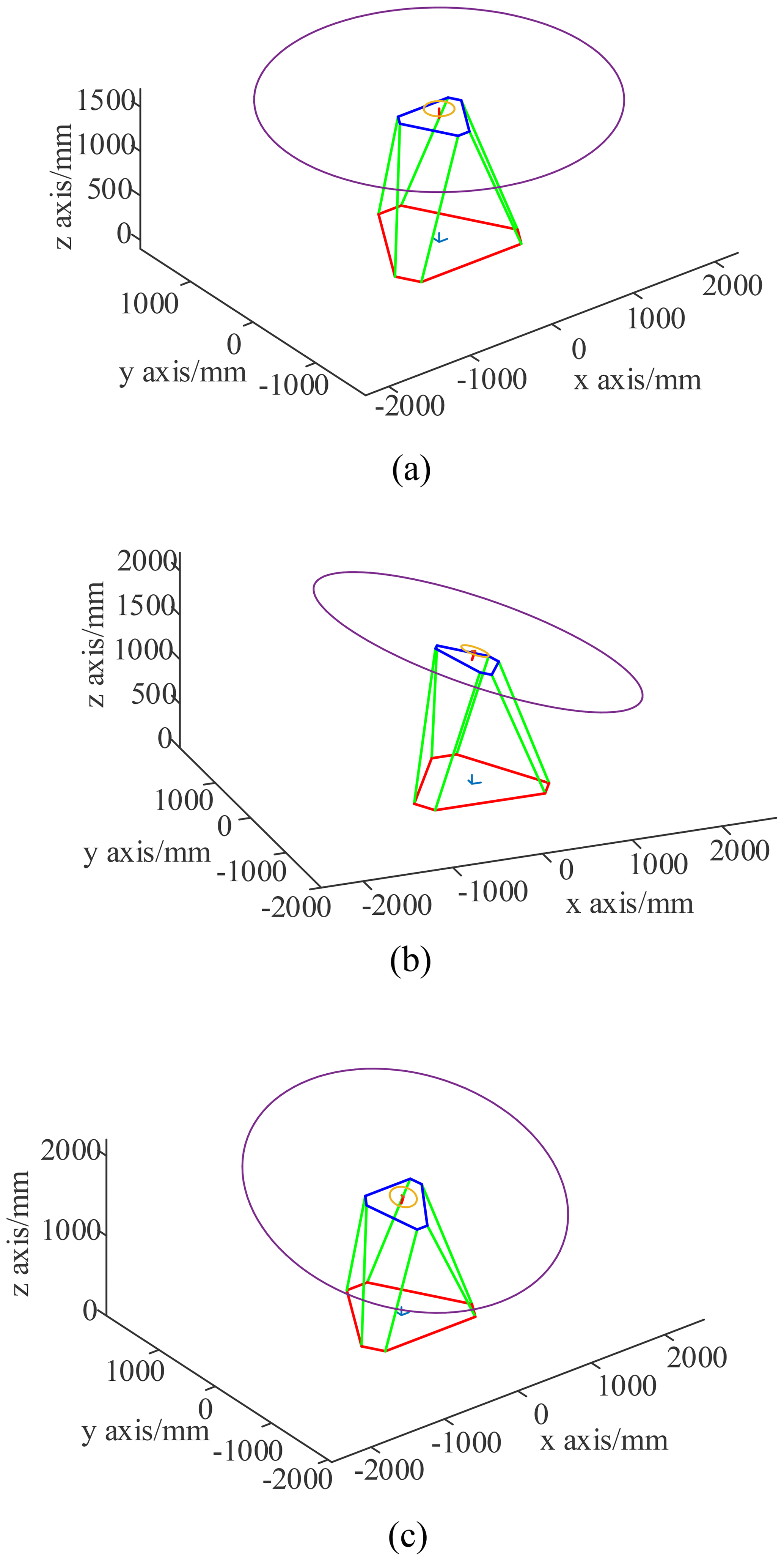
Figure 5Three motion forms of the parallel antenna. (a) Initial position. (b) Roll motion (20∘). (c) Pitch motion (20∘).
The simulation results show that the parallel antenna can achieve the motion in a roll (±20∘) and a pitch (±20∘).
3.2 Dynamics simulation of parallel antenna
According to the requirements of antenna motion range and bearing performance, the virtual prototype modeling and assembly are completed. The prototype model of the 1.8 m aperture parallel antenna mechanism is shown in Fig. 6.
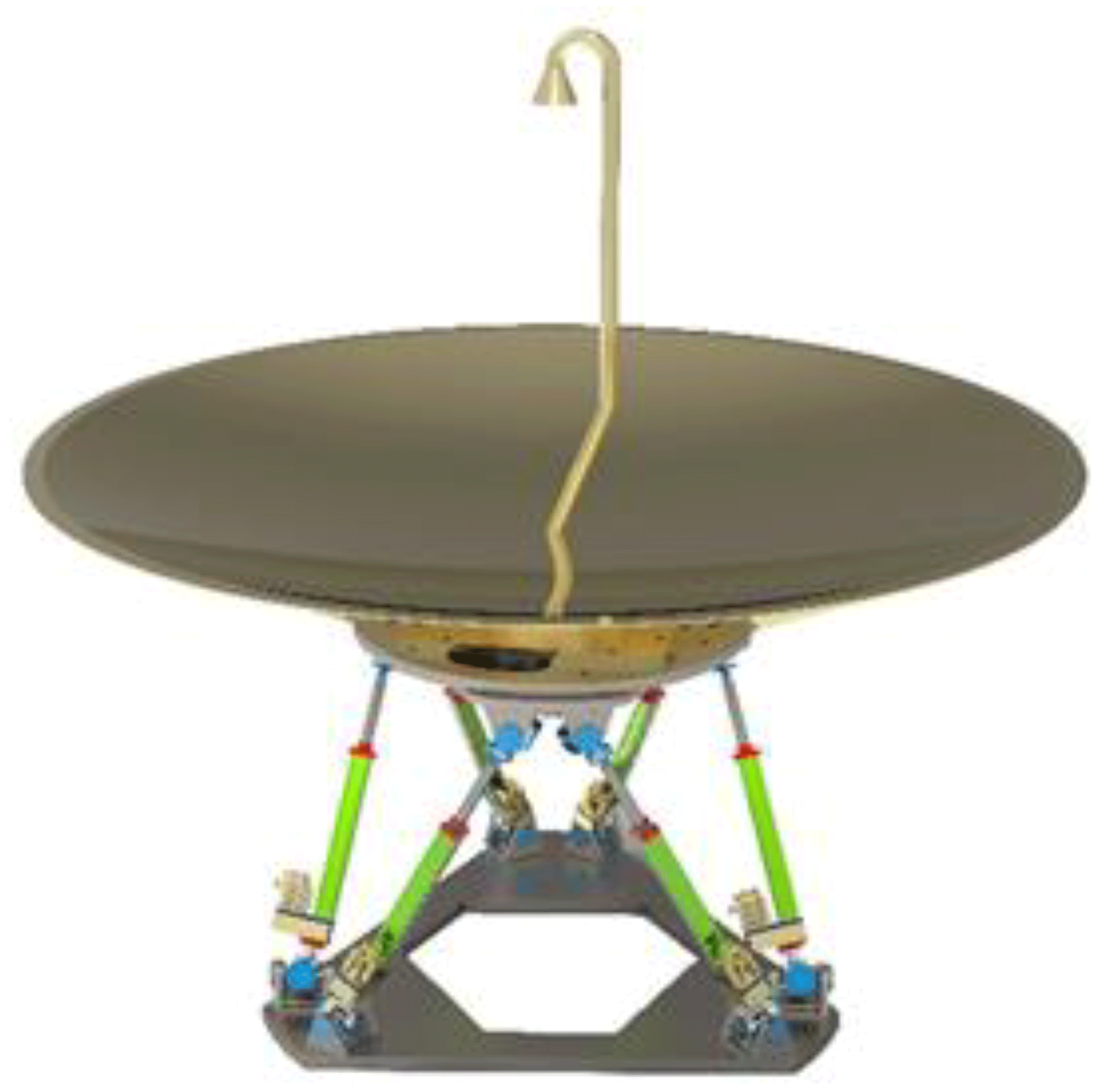
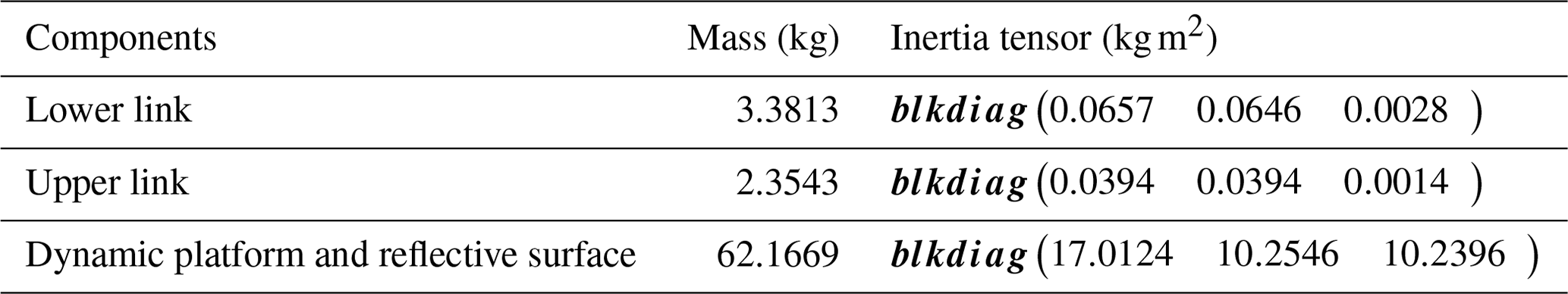
Combined with the actual working conditions of the antenna on the swing index and swing period requirements, the parallel antenna dynamics simulation is carried out based on the analysis of the parallel antenna horizontal roll and pitch motion state. Based on Adams software, the following dynamics simulation is carried out for two kinds of motion states of parallel antenna. The structure and mass parameters of the parallel antenna are shown in Table 1, based on SolidWorks software measurements.
Further considering the load carrying capacity of the actual operating link of the parallel antenna, the parallel antenna no load and 10 t load dynamics simulations are carried out, respectively. The simulation obtained the actuation force of each branch of the roll (20∘) and pitch (20∘) motions, as shown in Figs. 7 and 8.
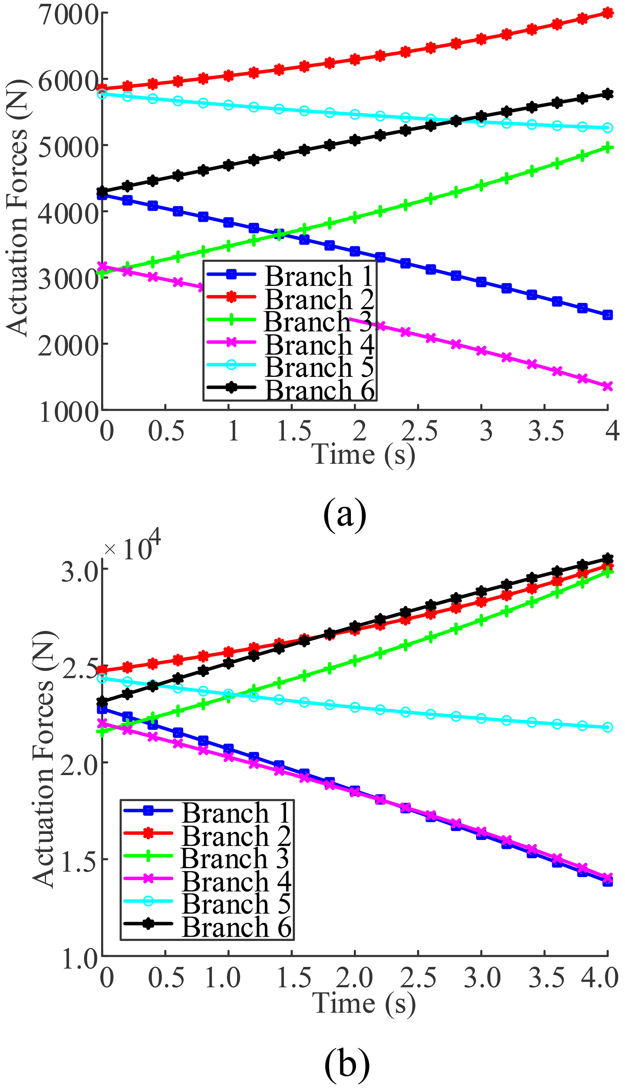
Figure 7Dynamic simulation curves of roll (20∘). (a) No load state. (b) The 10 t load state.
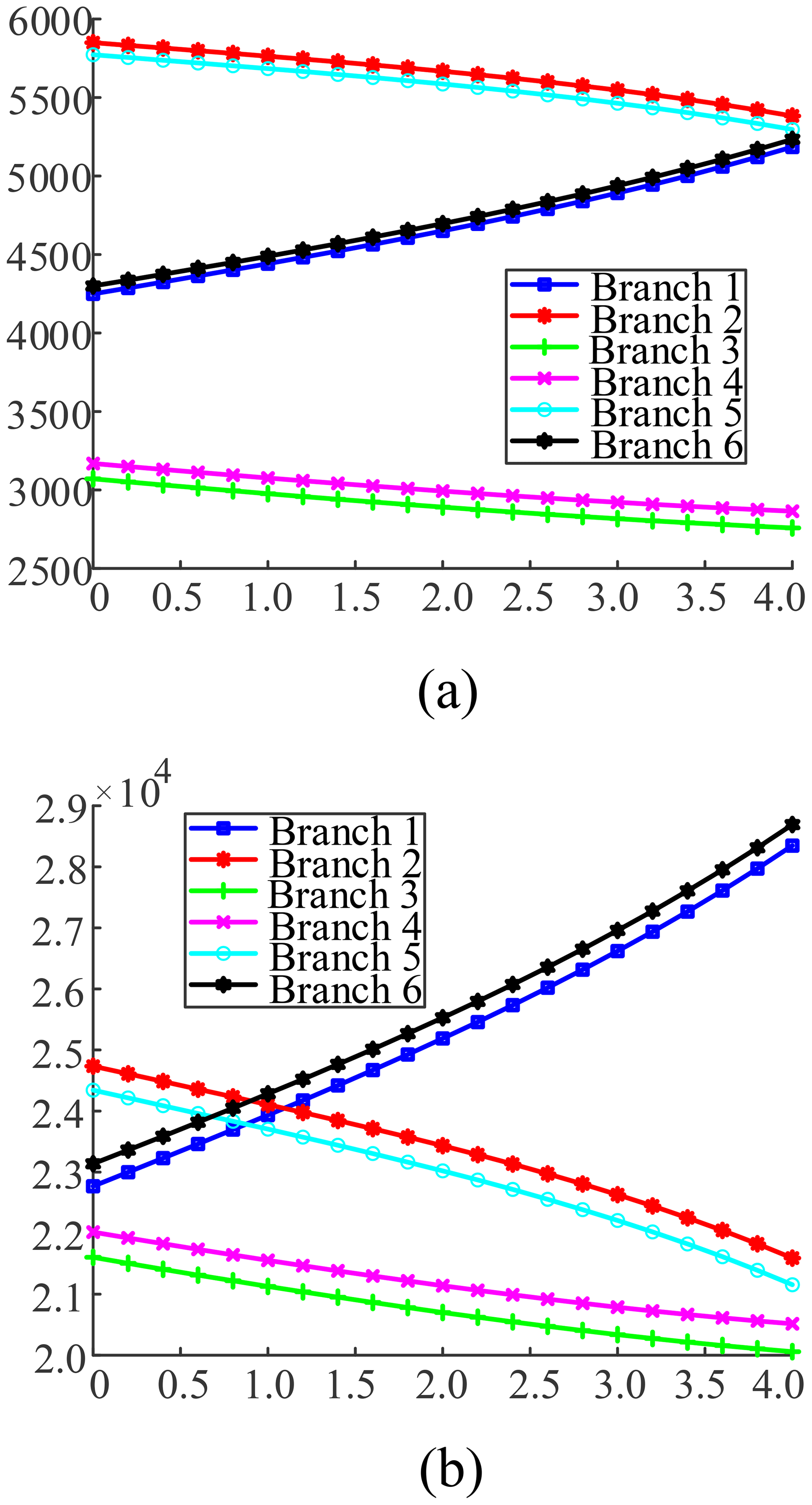
Figure 8Dynamic simulation curves of pitch (20∘). (a) No load state. (b) The 10 t load state.
According to Figs. 7 and 8, the parallel antenna, in accordance with the roll (20∘), pitch (20∘), no load, and 10 t load, exhibit a linear change for each branch actuation force, and the maximum actuation force of each branch at no load and the 10 t load is shown in Table 2.
Table 2Maximum actuation forces of three kinds of swing mode actuation.

By looking at the results of the simulation analysis of the parallel antenna's roll and pitch dynamics, it becomes clear that, when the parallel antenna is in roll motion, the maximum actuation force is about 7000.5 N at no load, and the maximum actuation force is about 30517.1 N at 10 t load. The results of the dynamics simulation analysis provide a reference for the selection of the parallel antenna actuator.
Vibration analysis seeks to suppress the vibration response of a system by analyzing the frequency response signal and modal analysis. The vibration characteristics of the parallel antenna are studied using the vibration module in Adams software. According to the structural characteristics and operating requirements of the parallel antenna, the vibration characteristics of the parallel antenna are simulated in a typical operating attitude with the help of the Adams vibration analysis module.
4.1 Vibration characteristics analysis of parallel antenna
In the initial position of the parallel antenna, three sinusoidal excitation forces with a zero-phase angle along the coordinate axis are set at the centroid of the moving platform. The output channel is set at the centroid of the moving platform, and the tension spring dampers with the stiffness coefficients N m−1 and N m−1 are added to the prismatic joint. The sixth-order modes correspond to the 6 DOF of the parallel antenna. Considering the motion characteristics of the parallel antenna, the vibration characteristics of the initial position and roll (20∘) are selected for simulation. The natural frequencies of each order mode of the parallel antenna in the roll posture are shown in Table 3.
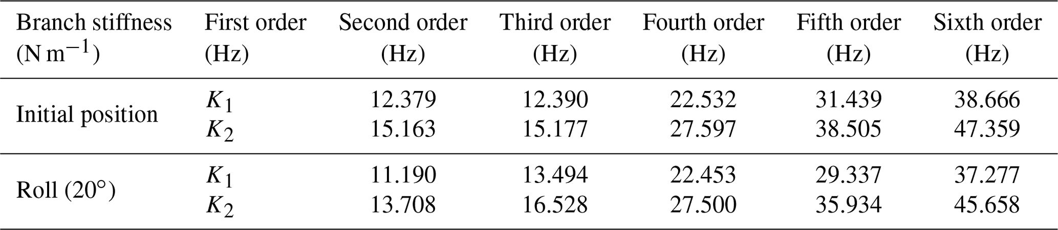
According to the simulation analysis results of vibration characteristics of parallel antenna in Table 3, the natural frequencies of each order of the parallel antenna are related to the branch stiffness. When the branch stiffness increases, the natural frequencies of each order increase. With the parallel antenna roll angle increase, the second-order natural frequency becomes larger, and the rest of the order of the natural frequency is reduced. When the parallel antenna is in the roll (20∘), and the branch stiffness is K1 and K2, the minimum value of the first-order natural frequency is 11.190 and 13.708 Hz, respectively. Appropriately increasing the branch stiffness of the parallel antenna can improve the natural frequencies of each order of the parallel antenna and help to improve the vibration characteristics of the parallel antenna.
4.2 Harmonic response analysis of parallel antenna
The harmonic response analysis can learn the deformation of the parallel antenna under a specific simple harmonic load. The following harmonic response analysis is performed for parallel antennas under different branch actuation stiffness and different positional conditions, respectively. We apply stress with an amplitude of 500 N in the x, y, and z directions of the center of the moving platform of the antenna mechanism. The structural damping ratio is set to 0.02, the frequency range of the simple harmonic force is set to 0 to 100 Hz, and the number of load steps is set to 50. The displacement response curves of the dynamic platform along the x, y and z directions at the initial position and roll (20∘) are shown in Figs. 9 and 10.
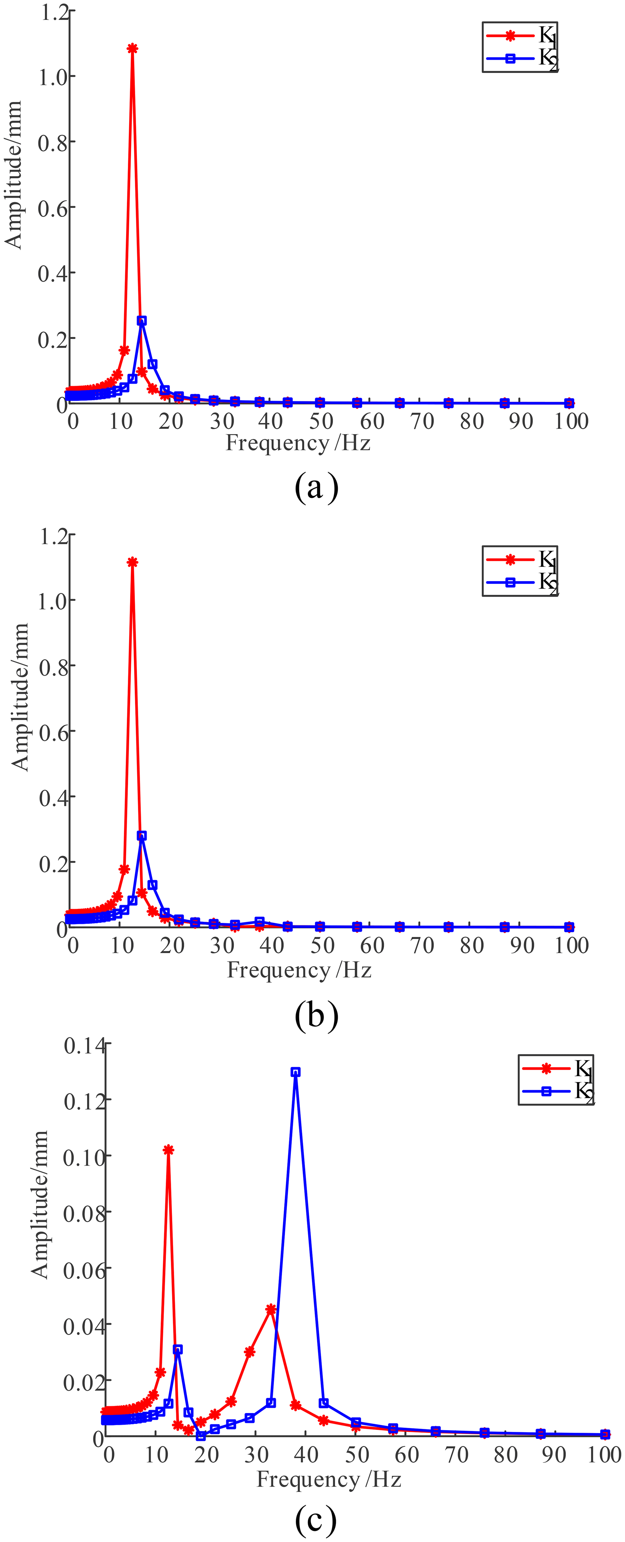
Figure 9Displacement responses of the initial position. (a) x-axis direction. (b) y-axis direction. (c) z-axis direction.
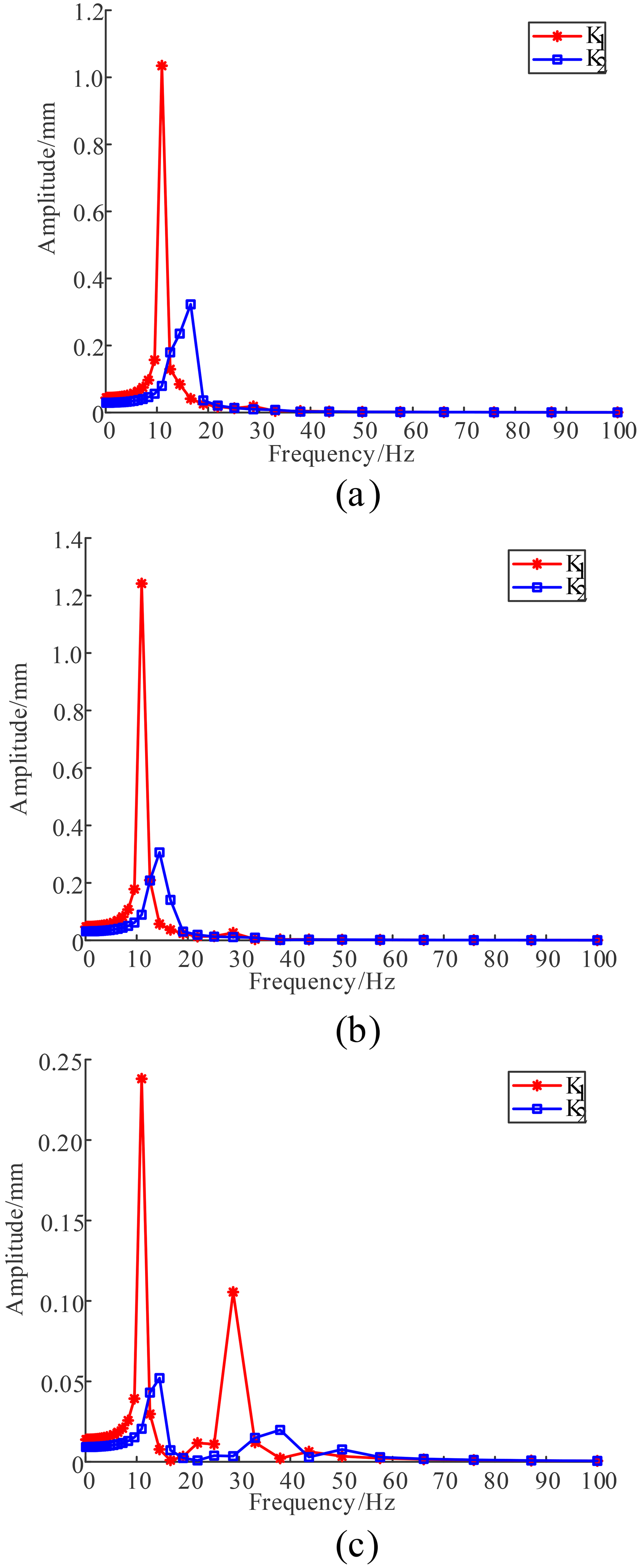
Figure 10Displacement responses of the roll (20∘). (a) x-axis direction. (b) y-axis direction. (c) z-axis direction.
According to Figs. 9 and 10, the maximum displacement response and corresponding frequency of the parallel antenna in the initial position and roll (20∘) are also shown in Table 4.
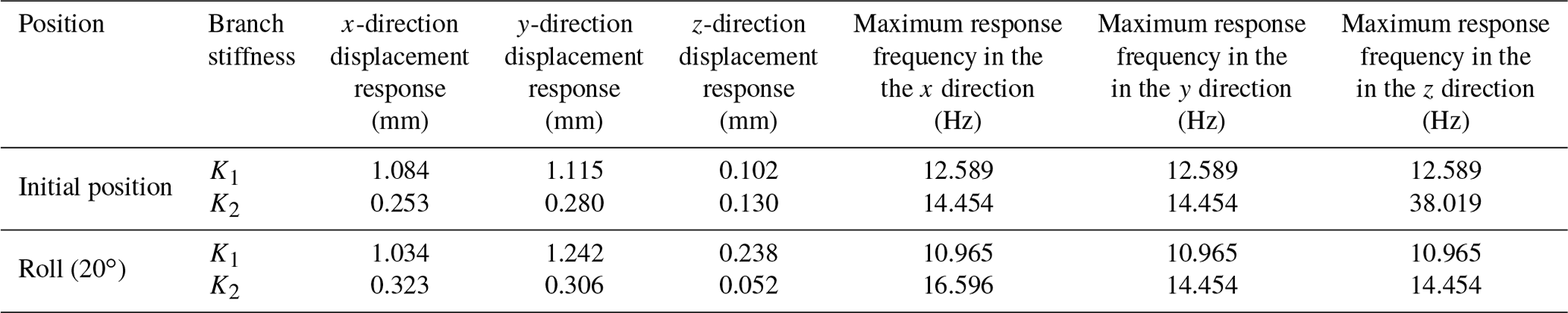
It can be seen from Table 4 that, when the initial position branch stiffness is K1, the maximum displacement responses of the moving platform in the x, y, and z directions are 1.084, 1.115, and 0.102 mm, respectively, and the corresponding excitation rates are 12.589 Hz, which is close to the first and second natural frequencies. When the branch stiffness is K2, the maximum displacement responses of the dynamic platform in the x, y, and z directions are 0.2530, 0.280, and 0.130 mm, corresponding to the excitation rate of 14.454 and 38.019 Hz, which are close to the first, second, and fourth natural frequencies of the mechanism. When the branch stiffness of the roll (20∘) is K1, the maximum displacement responses of the moving platform in the x, y, and z directions are 1.034, 1.242, and 0.238 mm, respectively, and the corresponding excitation rates are 10.965 Hz, which is close to the first natural frequency of the mechanism. When the branch stiffness is K2, the maximum displacement responses of the dynamic platform in the x, y, and z directions are 0.323, 0.306, and 0.052 mm, corresponding to the excitation rate of 16.596 and 14.454 Hz, which are close to the first and second natural frequencies of the mechanism. Therefore, the first, second, and fourth natural frequencies of the parallel antenna are sensitive frequencies. To maintain better dynamic characteristics, the system excitation frequency should avoid the above three groups of frequencies.
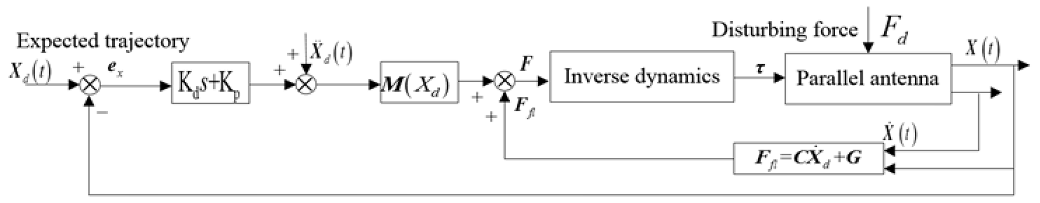
The control strategy based on the dynamic model is helpful to improve the dynamic performance of the parallel antenna. The inverse dynamics control framework of parallel antenna based on workspace is shown in Fig. 11. According to the requirements of the pitch and azimuth motion of the parallel antenna, we set the expected motion track Xd(t) of the antenna reflector center. The deviation between the actual motion track X(t) and the expected motion track Xd(t) is ex, and the gain acceleration is obtained by multiplying the deviation ex and the controller gain Kds+Kp. We multiply the sum of the gain acceleration and the expected acceleration by the mass matrix M(Xd). Combined with the gain force Ffl obtained from the feedback of the closed-loop system, the actuation force vector τ of the parallel antenna actuation joint is obtained through the inverse dynamics model. Through the workspace-based inverse dynamics closed-loop control algorithm, the characteristic trajectory of the parallel antenna is controlled.
The control system simulation of parallel antenna mechanism is carried out based on MATLAB. The simulation time is set as 2 s, and the simulation step is set as 0.1 s. The trajectory tracking error in the parallel antenna for the completing pitch, azimuth, and yaw is shown in Fig. 12.
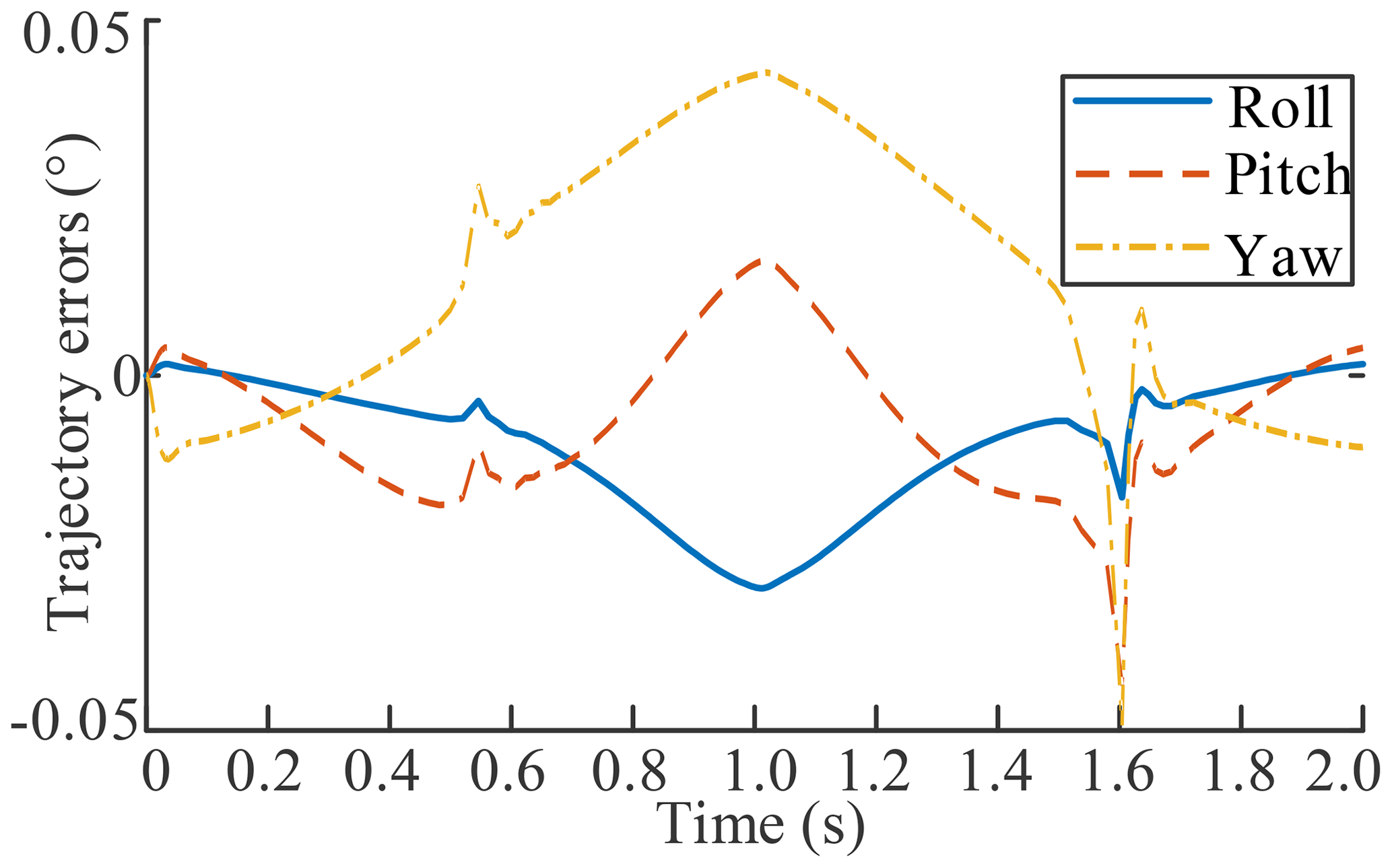
As shown in Fig. 12, the tracking error range of the parallel antenna, based on inverse dynamics control in the workspace, is ±0.05∘. The control strategy based on dynamics model helps to improve the antenna control accuracy.
The closed-form dynamics equation of the 1.8 m aperture 6 DOF parallel antenna is established. Based on the vibration theory, the vibration equation of the parallel antenna system is derived, and the relationship between the mechanism's natural frequency, displacement response, and resonance frequency is obtained. The simulation verifies the pitch and roll motion attitude of the parallel antenna. And, considering the actual operation carrying capacity of parallel antenna, a parallel antenna no load and 10 t load dynamics simulation is carried out. The simulation, based on the Adams vibration analysis module, obtains the natural frequency and vibration pattern of the initial position and roll (20∘) of the parallel antenna, which can help improve the vibration characteristics of the system by appropriately increasing the branch stiffness of the parallel antenna. The results of harmonic response analysis show that the parallel antenna dynamic platform produces the maximum displacement response in the x, y, and z directions, and the system excitation frequency should be as far as possible from the first, second, and fourth natural frequencies. Based on the dynamic model, the closed-loop motion control strategy of the parallel antenna mechanism is established. The tracking error in the pitch and azimuth motion of the parallel antenna in the workspace is within ±0.05∘, which can meet the requirements of the trajectory tracking performance of the antenna.
The code of the paper is not publicly accessible. According to the requirements of the research project, relevant codes cannot be disclosed temporarily and are available upon reasonable request from the corresponding author.
No data sets were used in this article.
GZ and XX conceptualized the project, developed the methodology, prepared the original draft, and developed the software. JH curated the data, reviewed and edited the paper, developed the software, visualized the project, and validated the results. JG supervised the project and was responsible for the project administration. All authors have read and agreed to the published version of the paper.
The contact author has declared that none of the authors has any competing interests.
Publisher's note: Copernicus Publications remains neutral with regard to jurisdictional claims in published maps and institutional affiliations.
This research has been supported by the Natural Science Foundation of Jiangsu Province of China (grant no. BK20220649) and Key R&D Program of Jiangsu Province (grant no. BE2022062).
This paper was edited by Daniel Condurache and reviewed by three anonymous referees.
Altuzarra, O., Macho, E., Aginaga, J., and Petuya, V.: Design of a solar tracking parallel mechanism with low energy consumption, P. I. Mech. Eng. C-J. Mec., 229, 566–579, https://doi.org/10.1177/0954406214537249, 2015.
Asadi, F. and Sadati, S. H.: Full dynamic modeling of the general Stewart platform manipulator via Kane's method, IJST-T. Mech. Eng., 42, 161–168, https://doi.org/10.1007/s40997-017-0091-3, 2018.
Abid, M., Yu, J. J., Xie, Y., and Salam, A.: Conceptual design, modeling and compliance characterization of a novel 2-DOF rotational pointing mechanism for fast steering mirror, Chinese J. Aeronaut., 33, 3564–3574, https://doi.org/10.1016/j.cja.2020.03.032, 2020.
Bang, J. L., Li, K. P., and Jia, C.: Dynamic performance study of Stewart parallel mechanism based on natural frequency, Appl. Mech. Mater., 635, 1246–1250, https://doi.org/10.4028/www.scientific.net/AMM.635-637.1246, 2014.
Corinaldi, D., Callegari, M., and Angeles, J.: Singularity-free path-planning of dexterous pointing tasks for a class of spherical parallel mechanisms, Mech. Mach. Theory, 128, 47–57, https://doi.org/10.1016/j.mechmachtheory.2018.05.006, 2017.
Cheng, M., Chen, Z., and Fang, Y.: Mechanical-performance-oriented optimization design of vibration isolation platform based on parallel mechanism, J. Vib. Eng. Technol., 32, 1–9, https://doi.org/10.16385/j.cnki.issn.1004-4523.2019.01.001, 2019.
Chen, W., Tong, J. Q., Yang, H. H., Liu, F. L., and Qin, Z.: Modeling and vibration analysis of a 3-UPU parallel vibration isolation platform with linear motors based on MS-DT-TMM, Shock Vib., 2021, 9918097, https://doi.org/10.1155/2021/9918097, 2021.
Furqan, M., Suhaib, M., and Ahmad, N.: Studies on Stewart platform manipulator: A review, J. Mech. Sci. Technol., 31, 4459–4470, https://doi.org/10.1007/s12206-017-0846-1, 2017.
Guo, J. W., Zhao, Y. S., Xu, Y. D., Zhang, G. X., and Yao, J. T.: A novel modular deployable mechanism for the truss antenna: Assembly principle and performance analysis, Aerosp. Sci. Technol., 105, 105967, https://doi.org/10.1016/j.ast.2020.105976, 2020.
Guo, J. W., Zhao, Y. S., Xu, Y. D., and Zhang, G. X.: Mechanics analysis and structural design of a truss deployable antenna mechanism based on 3RR-3URU tetrahedral unit, Mech. Mach. Theory., 171, 104749, https://doi.org/10.1016/j.mechmachtheory.2022.104749, 2022.
Guo, H. B. and Li, H. R.: Dynamic analysis and simulation of a six degree of freedom Stewart platform manipulator, P. I. Mech. Eng. C-J. Mec., 220, 61–72, https://doi.org/10.1243/095440605X32075, 2006.
Huang, Z., Li, Q. C., and Ding, H. F.: Theory of parallel mechanisms, Springer, Dordrecht, 4–15, : ISBN: 9789400742000, 2013.
Guo, J. W., Zhao, Y. S., Zhang, G. X., Liu, E. B., Liu, B. Q., and Xu, Y. D. Configuration synthesis and unfolding stiffness characteristics analysis of a truss antenna connecting mechanism based on URU-RR-URU hexagonal deployable unit, Mech. Mach. Theory, 177, 105047, https://doi.org/10.1016/j.mechmachtheory.2022.105047, 2022.
Hu, B., Zhang, L. D., and Yu, J. J.: Kinematics and dynamics analysis of a novel serial-parallel dynamic simulator, J. Mech. Sci. Technol., 30, 5183–5195, https://doi.org/10.1007/s12206-016-1036-2, 2016.
Hoevenaars, A. G. L., Krut, S., and Herder, J. L.: Jacobian-based natural frequency analysis of parallel manipulators, Mech. Mach. Theory, 148, 103775, https://doi.org/10.1016/j.mechmachtheory.2019.103775, 2019.
Jiao, J., Wu, Y., Yu, K. P., and Zhao, R.: Dynamic modeling and experimental analyses of Stewart platform with flexible hinges, J. Vib. Control., 25, 151–171, https://doi.org/10.1177/1077546318772474, 2019.
Kalani, H., Rezaei, A., and Akbarzadeh, A.: Improved general solution for the dynamic modeling of Gough-Stewart platform based on principle of virtual work, Nonlinear Dynam., 83, 2393–2418, https://doi.org/10.1007/s11071-015-2489-z, 2016.
Pedrammehr, S., Mahboubkhah, M., and Khani, N.: Improved dynamic equations for the generally configured Stewart platform manipulator, J. Mech. Sci. Technol., 26, 711–721, https://doi.org/10.1007/s12206-011-1231-0, 2012.
Qian, P., Pu, C., and Liu, L.: Development of a new high-precision friction test platform and experimental study of friction characteristics for pneumatic cylinders, Meas. Sci. Technol., 33, 065001, https://doi.org/10.1088/1361-6501/ac51a6, 2022.
Song, Y. M., Qi, Y., Dong, G., and Sun, T.: Type synthesis of 2-DOF rotational parallel mechanisms actuating the inter-satellite link antenna, Chinese J. Aeronaut., 29, 1795–1805, https://doi.org/10.1016/j.cja.2016.05.005, 2016.
Staicu, S.: Dynamics of the 6-6 Stewart parallel manipulator, Robot. Cim.-Int. Manuf., 27, 212–220, https://doi.org/10.1016/j.rcim.2010.07.011, 2011.
Stewart, D.: A platform with six degrees of freedom, P. I. Mech. Eng. C-J. Mec., 180, 371–386, https://doi.org/10.1243/PIME_PROC_1965_180_029_02, 1965.
Tsal, L. W.: Solving the inverse dynamics of a Stewart-Gough manipulator by the principle of virtual work, J. Mech. Des.-T. ASME, 122, 3–9, https://doi.org/10.1115/1.533540, 2000.
Wu, P. D., Xiong, H. G., and Kong, J. Y.: Dynamic analysis of 6-SPS parallel mechanism, Int. J. Mech. Mater. Des., 8, 121–128, https://doi.org/10.1007/s10999-012-9181-y, 2012.
Yang, J. F., Xu, Z. B., Wu, Q. W., Zhu, M. C., and He, S.: Dynamic modeling and control of a 6-DOF micro-vibration simulator, Mech. Mach. Theory, 104, 350–369, https://doi.org/10.1016/j.mechmachtheory.2016.06.011, 2016.
Zhang, G. X., Guo, J. W., Hou, Y. L., and Zeng, D. X. Analysis of the PU-2UPS antenna parallel mechanism, J. Mech. Sci. Technol., 35, 717–728, https://doi.org/10.1007/s12206-021-0132-0, 2021.
Zhang, G. X., Zheng, D. H., Guo, J. W., Hou, Y. L., and Zeng, D. X.: Dynamic modeling and mobility analysis of the 3-R(RRR)R+R hybrid antenna mechanism, Robotica, 39, 1485–1503, https://doi.org/10.1017/S0263574720001290, 2021.
Zhao, T. S., Geng, M. C., Chen, Y. H., Li, E. W., and Yang, J. T.: Kinematics and dynamics Hessian matrices of manipulators based on screw theory, Chin. J. Mech. Eng.-En., 28, 226–235, https://doi.org/10.3901/CJME.2014.1230.182, 2015.
Zhan, Y., Tian, H. C., Xu, J. A., Wu, S. F., and Fu, J. S.: A novel three-SPR parallel platform for vessel wave compensation, J. Mar. Sci. Eng., 8, 1013–1035, https://doi.org/10.3390/JMSE8121013, 2020.
Zhang, J. T., Song Y. M., and Liang, D.: Mathematical modeling and dynamic characteristic analysis of a novel parallel tracking mechanism for inter-satellite link antenna, Appl. Math. Model., 93, 618–643, https://doi.org/10.1016/j.apm.2020.12.020, 2020.
- Abstract
- Introduction
- Dynamic modeling of parallel antenna
- Simulation analysis of parallel antenna
- Modal analysis of parallel antenna
- Control strategy based on the dynamic model
- Conclusions
- Code availability
- Data availability
- Author contributions
- Competing interests
- Disclaimer
- Financial support
- Review statement
- References
- Supplement