the Creative Commons Attribution 4.0 License.
the Creative Commons Attribution 4.0 License.
 | 30 Sep 2021
Analytical solution to contact characteristics for a variable hyperbolic circular-arc-tooth-trace cylindrical gear
Rui Guo
Yongqiao Wei
Yongping Liu
Dawei Li
Dong Yang
Gang Zhao
The variable hyperbolic circular-arc-tooth-trace (VH-CATT) cylindrical gear is a new type of gear. In order to research the contact characteristics of the VH-CATT cylindrical gear, tooth surface mathematical models of this kind of gear pair are derived based on the forming principle of the rotating double-edged cutting method with great cutter head in this regard. Then, according to the differential geometry theory and Hertz theory, the formula of the induced normal curvature and equation of the contact ellipse are derived based on the condition of continuous tangency of two meshing surfaces, which proves that the contact form of VH-CATT cylindrical gear is point contact. The present work establishes analytical solutions to research the effect of different parameters for the contact characteristic of the VH-CATT cylindrical gear by incorporating elastic deformation on the tooth surface, which have shown that the module, tooth number and cutter radius have a crucial effect on the induced normal curvature and contact ellipse of the VH-CATT cylindrical gear in the direction of tooth trace and tooth profile. Moreover, a theoretical analysis solution, a finite element analysis and the gear tooth contact pattern are carried out to verify the correctness of the computerized model and to investigate the contact type of the gear; it is verified that the contact form on the concave surface of the driving VH-CATT cylindrical gear rotates from dedendum at the heel to the addendum at toe and is an instantaneous oblique ellipse due to elastic deformation of the contact tooth profile, and the connecting line of the ellipse center is the contact trace path. It is indicated that the research results are beneficial for research on tooth break reduction, pitting, wear resistance and fatigue life improvement of the VH-CATT cylindrical gear. The results also have a certain reference value for development of the VH-CATT cylindrical gear.
- Article
(812 KB) - Full-text XML
- BibTeX
- EndNote


The variable hyperbolic circular-arc-tooth-trace (VH-CATT) cylindrical gear is a new kind of mechanical transmission part (Wei et al., 2018b). Comparing with the involute spur gear and helical gear, the VH-CATT cylindrical gear has the arc tooth line, as well as better meshing performance, meaning it has higher contact ratio and no axial force (Wei et al., 2018a). These factors mean that the gear can bear higher loading, have higher transmission efficiency and have a more stable transmission (Song et al., 2006; Di et al., 2006; Xiao et al., 2013). According to the current investigated references (Wang et al., 2012; Zhao et al., 2016; Tang et al., 2016; Zhang et al., 2016; Wei et al., 2017; Sun et al., 2016; Luo et al., 2018), the complete theoretical system about contact characteristic for the VH-CATT cylindrical gear has not been studied up to now. And the contact forms of the VH-CATT cylindrical gear have been strictly proved by a mathematical method. However, the contact characteristic of the VH-CATT cylindrical gear has a great influence on the gear's stability, reliability, structure and noise. Therefore, the design process of the entire VH-CATT cylindrical gear pair needs to be optimized, and it will be hindered by the complexity of the contact phenomenon. In the process of gear manufacturing, tooth contact analysis (TCA) is an effective method for evaluating meshing performance of gear, and it has been widely used in milling (Litvin et al., 2006), hobbing (Fan, 2006) and grinding (Fong and Chen, 2016). Researchers have done a great deal of work on TCA for different types of gears: cylindrical gear (Fuentes et al., 2014), spiral bevel gears (Kawasaki and Tsuji, 2010), hypoid gears (Fan, 2007), face gears (Litvin et al., 2001), worm gears (Litvin et al., 2002) and noncircular gears (Zheng et al., 2018). In addition, although the tooth geometry of a single gear is determined by its manufacturing process, the resulting contact characteristics are always a consequence of interactions between both gear pair elements. Because of this, a substantial of research work of analyzing and optimizing single gear pairs has already been done by experimental testing or computerized tooth contact analysis (Litvin et al., 2006; Simon, 2011; Kolivand and Kahraman, 2010; Vivet et al., 2018; Fuentes et al., 2014; Tseng and Tsay, 2001). Aiming at exploring the key performance of a gear pair, the simulation analysis of the gear meshing process was carried out without the expensive prototype and experimental test. In the cause of evaluating the quality of a gear pair under loading conditions, it is a common practice to extend gear contact analysis to the finite element analysis of gear pair. The mathematical model of curvilinear cylindrical gears machined by the same face-milling cutter was established, and the undercutting conditions and contact characteristics of this type of curvilinear cylindrical gear were analyzed (Tseng and Tsay, 2004, 2005). A mathematical model of a curvilinear cylindrical gear with variable tooth trace generated by a pair of independent face-milling cutters was proposed, its contact characteristics were analyzed, and the stress analysis was accomplished (Parsons et al., 2004). In one reference (Tseng and Tsay, 2006), a new method of continuous indexing of manufacturing of curvilinear cylindrical gear drives by hob-cutters was proposed. The geometric mathematical model of that type of gear was described, and their undercutting conditions and contact characteristics were analyzed (Fuentes et al., 2014). The main curvature and normal curvature are the basic parameters which reflect the geometric characteristics of a tooth surface. The gear's transmission quality is determined by the curvature relationship between the conjugate tooth surfaces of the gear pair. And the contact form, contact characteristic and the contact stress of the gear pairs are also determined by the curvature of tooth surface.
In order to obtain an accurate contact detection between two meshing geometries, an accurate description of the respective geometry is required. According to the meshing theory and double-edged cutting method with great cutter head, the tooth surface equation of the VH-CATT cylindrical gear was derived in Sect. 2. Then, based on differential geometry theory and Hertz theory, the calculation formulas of the induced normal curvature and the contact ellipse were derived in Sect. 3, and the finite element analysis model of the VH-CATT cylindrical gear and the contact experiment were established. And this was used to verify the contact form of the VH-CATT cylindrical gear. In Sect. 4 the information about the effects of design parameters on induced normal curvature, contact ellipse and stress variation and distribution in meshing process was computed based on Hertz contact theory, and the math model was studied. The present study has certain reference value for the dynamic design and noise reduction of the VH-CATT cylindrical gear by the double-edged cutting method with great cutter head.
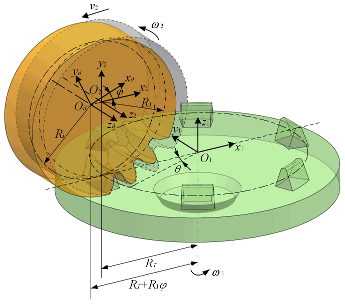
Based on the double-edged cutting method with great cutter head, the VH-CATT cylindrical gear is machined by the mutual movement of the cutter head installed on the rotating spindle and the gear blank. The fixed angle is always set between the inside and outside edge of the cutter and the cutter axis. The two conical surfaces are formed by the double-edged cutter in cutting process. The concave tooth surface is cut by the outside cutting edge. The convex tooth surface is cut by the inside cutting edge. In this way, the concave and convex tooth surfaces of the VH-CATT cylindrical gear can be formed by the generative movement between the cutter and the gear blank. The coordinate systems of the double-edged cutting method with great cutter head were set up as shown in Fig. 1. The coordinate system o1−x1, y1, z1 is connected with rotation axis of the cutter; o1 is located on the reference area of the cutter. The coordinate system od0−xd0, yd0, zd0 is also connected with the rotation axis of the cutter, and the location of coordinate origin od0 is the same as the coordinate system o1−x1, y1, z1. The coordinate system o2−x2, y2, z2 is connected with the gear blank of the VH-CATT cylindrical gear; o2 is located on the center of the gear blank. The coordinate system od−xd, yd, zd is also connected with the gear blank, and the location of coordinate origin od is the same as the coordinate system o2−x2, y2, z2, but it is a moving coordinate system.
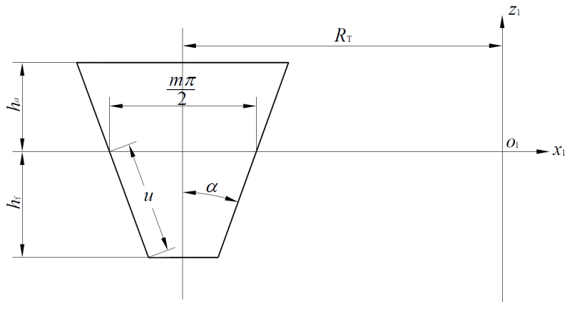
The geometric shape and parameters of the cutting edge are shown in Fig. 2, and the position vector equation of cutter surface in the moving coordinate system o1−x1, y1, z1 was expressed as
where u is the displacement from a random point on the cutting tool surface to the reference point on the direction of the cutting edge. α is the pressure angle of cutter. RT is the generative radius of the cutter. θ is known as tooth profile position angle, which is from the cutter to the end face of the gear blank in the manufacturing process, and its value is positive in the clockwise direction.
According to the spatial meshing theory and the trajectory relationship between cutting edge and gear blank in the coordinate system (combining the coordinate transformation matrix), the position vector equation of tooth surface of the VH-CATT cylindrical gear was derived. The transformation process is given as follows:
The transformation matrix M21 from the coordinate system o1−x1, y1, z1 to the coordinate system o2−x2, y2, z2 can be represented as
The transformation matrix Md2 from the coordinate system o2−x2, y2, z2 to the coordinate system od−xd, yd, zd can be represented as
So, the coordinate expression in the coordinate system od−xd, yd, zd could be expressed as
Based on the transformation matrix, the tooth surface equation of the VH-CATT cylindrical gear is given as
Where φ1 is the rotation angle of the gear blank. The symbol “±” represents the concave tooth surface, and symbol “∓” represents the convex tooth surface of the VH-CATT cylindrical gear. The tooth surface is the formed enveloping surface expressed by cutter parameter θ and rotation angle parameter φ1.
On the basis of the forming principle, the VH-CATT cylindrical gear is cut by the double-edged cutting method with great cutter head. The curvature radius of the concave tooth surface is greater than the radius of the convex tooth surface. So the contact form of the VH-CATT cylindrical gear appears as the point contact. Because of the elasticity deformation under the load, the contact section becomes an ellipse from a contact point in the instantaneous contact point. And the center of the instantaneous contact ellipse overlaps with the theory contact point. In fact, in the entire process of gear meshing, the contact trace is a series of contact ellipses. The induced normal curvature and contact ellipse of the gear pair directly affect the contact characteristics of the gear transmission. In order to study the contact situation of the concave and convex tooth surfaces of the meshing pair, the induced normal curvature and the area of contact ellipse are regarded as the measurement index of the contact performance in this paper, and the influence rules of gear design parameters for the contact performance are analyzed.
3.1 Induced normal curvature
The contact of the gear pair in the meshing process is the result of interactional forces between two gear tooth surfaces, so it is not enough just to analyze one gear's normal curvature; instead, it is required to study the relative normal curvature of the tooth surfaces, namely, induced normal curvature. The induced normal curvature of conjugate tooth surfaces of a gear pair is regarded as an important reference which directly affects the lubrication condition and contact performance of a gear transmission device. The induced normal curvature can provide the theoretical foundation for evaluating the gear drive mechanism and choosing the gear parameter reasonably. According to the motion geometry method, binary vector method and relative differential method, the induced normal curvature is studied by many scholars in China and elsewhere. In this paper, the induced normal curvature of the VH-CATT cylindrical gear is derived systematically by using differential geometry and space meshing principle.
In general, the quality of transmission performance of the gear pair is evaluated by the absolute value of the induced normal curvature. In principle, the smaller the absolute value of the induced normal curvature is, the better the transmission performance of the gear pair is. Especially the minimum value of induced normal curvature is zero, which indicates that the transmission pair is in the perfect meshing position. Assuming that ΣI is the concave surface of the VH-CATT cylindrical gear and that ΣII is the convex surface of the VH-CATT cylindrical gear, then ΣI is tangent to ΣII at point M. The main directions of ΣI are and , and the main curvatures are and . The main directions of ΣII are and , and the main curvatures are and ; φI is the directed angle from to , and φg is the directed angle from to ; φ is the arbitrary directed angle from to e. The concave and convex surfaces have the same normal vector n at point M. The curvature relationship of the tangent surfaces is shown in Fig. 3.

The direction angle φ is from to the arbitrary direction e. Based on Euler's formula of normal curvatures, the normal curvatures of ΣI are expressed as
where , .
In the same direction, the normal curvatures of ΣII are expressed as
where , .
In the same direction, the induced normal curvature of the VH-CATT cylindrical gear is expressed as
The two main values of induced normal curvature of the VH-CATT cylindrical gear in the two main directions are expressed as
3.2 Contact ellipses
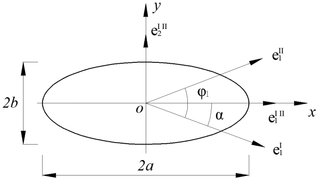
The contact from of the VH-CATT cylindrical gear is the point contact. Because of the elasticity deformation under the load, the contact section becomes an ellipse from a contact point in the instantaneous contact point. In fact, in the entire process of the gear meshing, the contact trace is a series of contact ellipses. The contact section appears as an ellipse, as shown in Fig. 4. The sizes of these contact ellipses will affect the contact performance of the gear pair. The gear surface's elastic deformation depends on the load, but it is generally considered a fixed value and equal to 0.00025 in. (0.00632 mm) under the light load. In this paper, the study mainly aimed at the light load, so let the elastic deformation δ be 0.00632 mm.
According to the above analysis, we assume the contact ellipse equation of the VH-CATT cylindrical gear as follows:
The long axis a and short axis b of the contact ellipse can be expressed as
Ellipse area can be represented as
3.3 Stress variation and distribution in the meshing process of the gear pair
To prove the validity of the computerized model and to study the contact type of the gear, a theoretical analysis solution, a finite element analysis and the gear tooth contact pattern are carried out. The contact point on the concave surface of the driving VH-CATT cylindrical gear moves from dedendum at the heel to the addendum at toe. The accurate 3D model of the VH-CATT cylindrical gear is set up by MATLAB and UG NX8.0. The gear parameters are as follow: tooth numbers z1=21 and z2=29, gear module m=4, tooth width B1=84 mm and B2=80 mm, tooth line radius RT=500 mm, and the rest of the parameters are based on the international standards. The geometric characteristic of the VH-CATT cylindrical gear is determined by the cutter radius, tooth number and module. The contact performance of the VH-CATT cylindrical gear is closely related to the tooth surface geometry characteristics and the transmission principle.
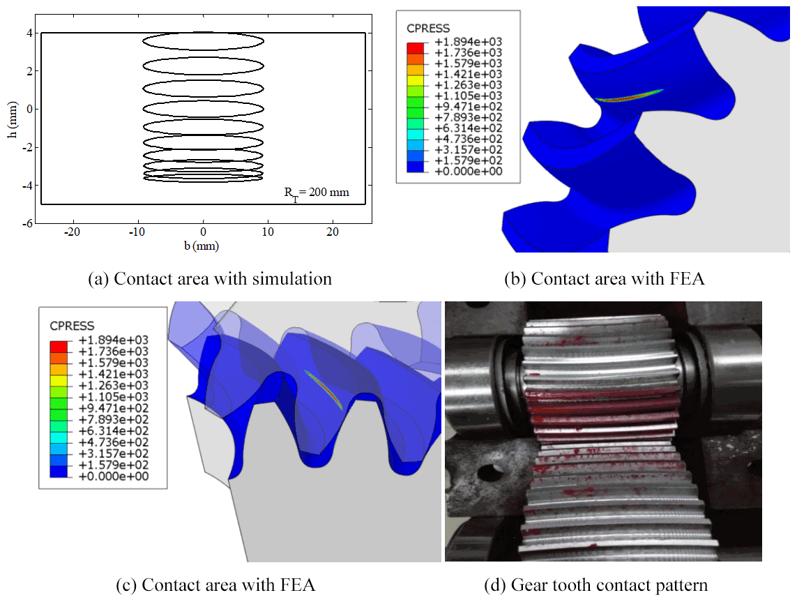
Figure 5Contact areas in the finite analysis and contact patterns in the rolling experiment.
To further verify the contact characteristics of the VH-CATT cylindrical gear, to obtain the theoretical rigid-body-based transmission errors and contact pattern and for the comparison purpose, finite element method (FEM) simulations are carried out on the VH-CATT cylindrical gear. The finite element model for contact analysis of the VH-CATT cylindrical gear is built into the ABAQUS software suite. A linear reduced integration cell is selected, considering the efficiency and accuracy of the analytical calculations (C3D8R). A reference point was established at the center of the gear. The gear establishes multipoint constraints (MPCs) with the two reference points, and the boundary conditions and constraints are imposed on the reference point. A fixed constraint is applied at the reference point of the driving wheel, with only 1 degree of freedom of rotation along the driving wheel, and a bending moment is applied at that point; at the driven wheel, the reference point applied a full fixation constraint. Considering friction, a surface–surface contact pair between concave and convex surfaces of the pinion is defined. The multiload steps are loaded on the driving gear gradually to figure out the initial contact of the meshing tooth pairs and convergence of contact analysis. The contact stresses can be acquired by releasing the rotational freedom of the driving gear and applying angular displacement to the driving gear axis. In the cause of minimizing the errors caused by structural deformation, the velocity applied to the pinion and the torque of the gear are set to be very small. The contact surfaces of the gears are set to contact pairs. The static universal solution is used.
Due to elastic deformation of the contact tooth profile, the point is compressed into a momentary oblique ellipse, and connecting line of the ellipse centers is the contact trace path in Fig. 5a. The contact form of the VH-CATT cylindrical gear is a cluster of elliptic families along the contact trace line in the meshing process. The computed contact contours of the VH-CATT cylindrical gear pairs are given in Fig. 5b, c. The contact contour of gear pairs at the meshing area is an ellipse, which further verifies that the contact type of the VH-CATT cylindrical gear under the load capacity is the ellipse. The largest contact stress is mainly distributed at the middle section position of the tooth root of pinion in the meshing process. The contact stress is along the direction of tooth trace, and the contact area extends to the full tooth width range. The contact pattern of the VH-CATT cylindrical gear type is given in Fig. 5d. The simple contact pattern experiment is conducted to show the contact pattern of this gear type. The contact area is the bright area on the tooth surfaces of pinion, which is easily observable and similar to the result of finite element analysis (FEA) shown in Fig. 5b, c. With the increase of load, the contact area of the gear can be extended to the full tooth width, and the gear pair has no tooth surface interference phenomenon in the meshing process. It should be noted that this simple experiment verifies just the correctness of the design and the consistency of computerized 3D model and real gear.
4.1 Effects of design parameters on induced normal curvature
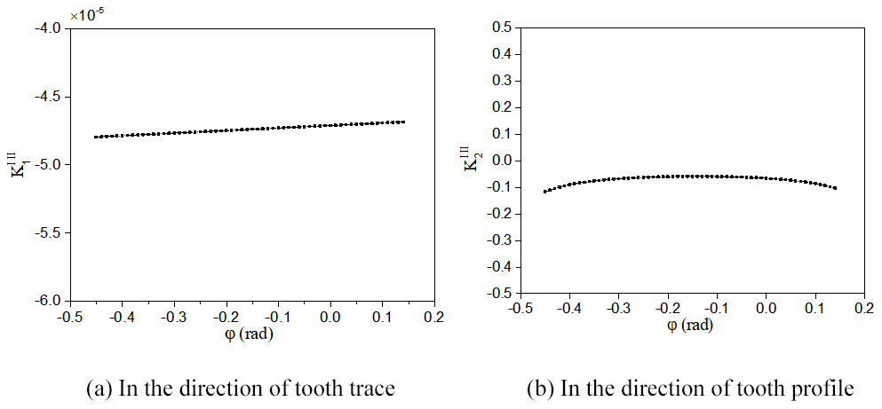
The contact strength and lubrication effect of the gear pair are influenced by the induced normal curvature. Figure 6 shows the variations of the induced normal curvature of the VH-CATT cylindrical gear in the two main directions from the tooth root to the tooth tip. It can be seen from Fig. 6 that the extent of variation of the induced normal curvature of the gear pair in the meshing process is very small at both main directions. The main value of the induced normal curvature in the direction of tooth trace is nearly close to zero; the main value of the induced normal curvature in the direction of tooth profile is negative. The results are consistent with the literature (Parsons et al., 2004), which shows that the induced normal curvature must be negative when the direction vector of common normal at the contact point of meshing tooth surface points to the airspace. This also proved that the phenomenon of gear profile interference during gear meshing did not occur, and the gear pair is in an ideal meshing position during the meshing process. Especially the absolute value of the induced normal curvature in the direction of tooth profile reaches minimum in the pitch circle. Meanwhile, this proved that the transmission performance of the VH-CATT cylindrical gear during the meshing process reaches the best effect near the pitch circle. And the smaller induced normal curvature makes the gear have a higher contact fatigue strength of tooth surface and bending fatigue strength of tooth root, which are consistent with results in the literature (Parsons et al., 2004) that the VH-CATT cylindrical gear has a higher contact fatigue strength of tooth surface and bending fatigue strength of tooth root.
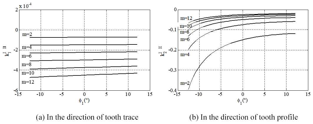
Investigation into the effect of module on the induced normal curvature of VH-CATT cylindrical gear during the meshing process is shown in Fig. 7; the induced normal curvature of the VH-CATT cylindrical gear in the direction of tooth trace increases with the increase of the gear module, but it still remains near zero. When the gear module increases, the induced normal curvature of the VH-CATT cylindrical gear in the direction of tooth profile increases because of the increasing tooth thickness due to the radius difference of the inner and outer cutter blades. Therefore, it is necessary for the gear design to choose the appropriate module.
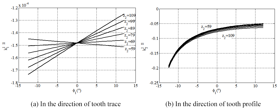
For investigation into the effect of tooth number on the induced normal curvature of the VH-CATT cylindrical gear during the meshing process, the tooth number of pinion and the driven gear for various tooth numbers remains unchanged. As shown in Fig. 8, when the tooth number of the driven gear increases, the induced normal curvature of the VH-CATT cylindrical gear in the direction of tooth trace remains unchanged at the initial meshing position φ1=0∘; thus, the induced normal curvature of the VH-CATT cylindrical gear in the direction of tooth trace changes regularly at the other meshing positions, but the scuffing domain happens near zero. Along with the increase of tooth number of the driven gear, the induced normal curvature of the VH-CATT cylindrical gear in the direction of tooth profile becomes bigger where the minus sign represents the direction.
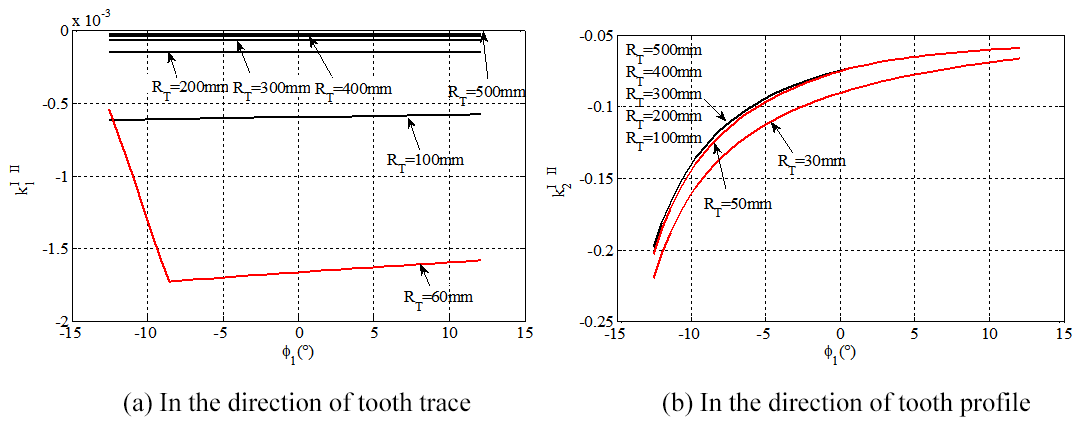
Effects of cutter radius on induced normal curvature of the VH-CATT cylindrical gear are shown in Fig. 9. The main value of induced normal curvature of VH-CATT cylindrical gear in the direction of tooth trace reduces and mainly reaches zero near the tooth trace as the cutter radius increases. When the cutter radius is larger, the variations of cutter radius have little effect on the induced normal curvature in the direction of tooth profile. Meanwhile, as shown Fig. 9a, when the cutter radius value is less than 60 mm, the curve of induced normal curvature appears to change suddenly. The reason for this is that when the cutter radius is too small, the gear cannot be cut. Therefore, when selecting the nominal cutter radius, the rotation axis of the cutter is at least ensured to be outside the boundary of the blade.
4.2 Effects of design parameters on contact ellipse
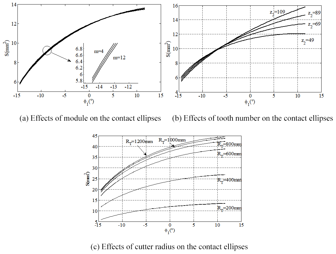
Investigation into the effects of design parameters on the area of contact ellipse of the VH-CATT cylindrical gear shown in Fig. 10, the design parameters are made of module, tooth number and cutter radius. It can be read from Fig. 10a that the variations of gear module have little effect on the area of contact ellipse. The area of contact ellipse generated at the tooth root part of the concave tooth surface of the driving pinion decreases with the increase of the module, but the changed law of area of contact ellipse generated at the tooth tip is opposite. It can be read from Fig. 10b that the variations of tooth number have the greater effects on the area of contact ellipse. The area of contact ellipse generated at the tooth root part of the concave tooth surface of the driving pinion decreases with the increase of the tooth number. With the increasing of the tooth number, the area of contact ellipse generated at the tooth tip part of the concave tooth surface of driving pinion increases, especially the contact ellipses close to the tooth tip are more affected by the tooth number, but the contact ellipses close to the tooth root for various tooth numbers remain unchanged. It can be seen from Fig. 10c that the area of contact ellipse reaches minimum when the cutter radius is equal to the 200 mm. The reason for this is the larger radius difference of the inner and outer cutter blades. As shown in Fig. 10c, the area of contact ellipse increases along with the increase of cutter radius, which leads to the contact area gradually spreading until the two teeth are in full engagement. When the cutter radius is greater than 800 mm, the variation of area of contact ellipse is very small with the increase of cutter radius.
In consideration of the elastic deformation on the concave and convex surfaces of the tooth, analytical solutions to the contact characteristics for the VH-CATT cylindrical gears are proposed according to the Hertz contact theory and differential geometry. The effects of the module, tooth number and cutter radius on the induced normal curvature and contact ellipses are investigated, which have shown that the module, tooth number and cutter radius have a crucial effect on the induced normal curvature and contact ellipse of the VH-CATT cylindrical gear in the direction of tooth trace and tooth profile. Furthermore, to prove the validity of the computerized model and explore the contact type of the gear, a theoretical analysis solution, a finite element analysis and the gear tooth contact pattern were carried out. The contact form is using the present contact mathematic model and is verified by the finite element analysis and the gear tooth contact pattern experiment. It is shown that gear pairs at the meshing area form an ellipse under the load capacity from the contact contours. The largest contact stress is mainly distributed at the middle section position of the tooth root of pinion in the meshing process. The contact stress is along the direction of tooth trace, the contact area gradually becomes larger and smaller, and the tooth force along the contact line is relatively uniform. Therefore, the transmission of the VH-CATT cylindrical gear is more stable than ordinary gear transmission.
All the code and data used in this paper can be obtained upon request to the corresponding author.
RG, YW, and YL conceived the presented idea. RG and YW established an overall paper research framework and the model. YL and DL conducted data calculation for the overall paper. GZ supervised the findings of this work. YW and DY collected and provided the model data. All the authors discussed the results and contributed to the final paper.
The contact author has declared that neither they nor their co-authors have any competing interests.
Publisher's note: Copernicus Publications remains neutral with regard to jurisdictional claims in published maps and institutional affiliations.
The authors would like to thank anonymous reviewers for their valuable comments and suggestions that enabled us to revise the paper.
This research was supported by the National Key Research and Development Program of China (grant no. 2019YFB2006402), National Natural Science Foundation of China (grant no. 52105058), the Open Fund of Hubei Key Laboratory of Mechanical Transmission and Manufacturing Engineering at Wuhan University of Science and Technology (grant no. MTMEOF2019B02) and the Hongliu Youth Fund of Lanzhou University of Technology (grant no. 07-062005).
This paper was edited by Daniel Condurache and reviewed by Yonghong Chen and two anonymous referees.
Di, Y. T., Hong, X. H., and Chen, M.: Generation principle of arcuate tooth trace cylindrical gear, Journal of Harbin Bearing, 27, 58–61, https://doi.org/10.3969/j.issn.1672-4852.2006.03.022, 2006.
Fan, Q.: Computerized modeling and simulation of spiral bevel and hypoid gear manufactured by gleason face hobbing process, ASME J. Mech. Des., 128, 1315–1327, https://doi.org/10.1115/1.2337316, 2006.
Fan, Q.: Enhanced algorithms of contact simulation for hypoid gear drives produced by face-milling and face-hobbing processes, ASME J. Mech. Des., 129, 31–37, https://doi.org/10.1115/1.2359475, 2007.
Fong, Z. H. and Chen, G. H.: Gear flank modification using a variable lead grinding worm method on a computer numerical control gear grinding machine, J. Mech. Des., 138, 2–10, https://doi.org/10.1115/1.4033919, 2016.
Fuentes, A., Ruiz-Orzaez R., and Gonzalez-Perez, I.: Computerized design, simulation of meshing, and finite element analysis of two types of geometry of curvilinear cylindrical gears, Comput. Meth. Appl. Mech. Eng., 272, 321–339, https://doi.org/10.1016/j.cma.2013.12.017, 2014.
Kawasaki, K. and Tsuji, I.: Analytical and experimental tooth contact pattern of large-sized spiral bevel gears in cyclo-palloid system, J. Mech. Des., 1323, 41–44, https://doi.org/10.1115/1.4001348, 2010.
Kolivand, M. and Kahraman, A.: An ease-offbased method for loaded tooth contact analysis of hypoid gears having local and global surface deviations, J. Mech. Des., 132, 1004–1008, https://doi.org/10.1115/1.4001722, 2010.
Litvin, F. L., Fuentes, A., and Howkins, M.: Design, generation and TCA of new type of asymmetric face-gear drive with modified geometry, Comput. Meth. Appl. Mech. Eng., 190, 5837–5865, https://doi.org/10.1016/S0045-7825(01)00201-8, 2001.
Litvin, F. L., Nava. A., Fan, Q., and Fuentes, A.: New geometry of face worm gear drives with conical and cylindrical worms: generation, simulation of meshing, and stress analysis, Comput. Meth. Appl. Mech. Eng., 91, 3035–3054, https://doi.org/10.1016/S0045-7825(02)00235-9, 2002.
Litvin, F. L., Fuentes, A., and Hayasaka, K.: Design, manufacture, stress analysis, and experimental tests of low-noise high endurance spiral bevel gear, Mech. Mach. Theory, 41, 83–118, https://doi.org/10.1016/j.mechmachtheory.2005.03.001, 2006.
Luo, L., Hou, L., Zhao, F., and Bai, Q. S.: Analysis on geometric characteristics of cylindrical gear with variable hyperbolic circular-arc-tooth-trace, Adv. Eng. Sci., 50, 171–179, https://doi.org/10.15961/j.jsuese.201700511, 2018.
Parsons, B. N., Walton, D., Andrei, L., and Andrei, G.: Non-standard cylindrical gears, Gear Technol., 21, 30–37, 2004.
Simon, V. V.: Influence of tooth modifications on tooth contact in face-hobbed spiral bevel gears, Mech. Mach. Theory, 46, 1980–1998, https://doi.org/10.1016/j.mechmachtheory.2011.05.002, 2011.
Song, A. P., Yi, H., Tang, W. C., Ni, X. H. Li, L. Y.: Involute arc cylindrical gear and its mesh characteristics, China Mechanical Engineering, 17, 1888–1892, https://doi.org/10.3321/j.issn:1004-132X.2006.18.005, 2006.
Sun, Z. J., Hou, L., Wang, J. G., Li, W., and Chang, Q. L.: Contact strength analysis of ciucular-arc-tooth-trace cylindrical gear, J. Braz. Soc. Mech. Sci. Eng., 38, 999–1005, https://doi.org/10.1007/s40430-014-0272-6, 2016.
Tang, R., Hou, L., and Zhou, B.: Modelling and strength analysis for manufactureorientedcylindrical gear with arcuate tooth trace, Australian Journal of Mechanical Engineering, 26, 88–94, https://doi.org/10.1080/14484846.2015.1093217, 2016.
Tseng, R. T. and Tsay, C. B.: Mathematical model and undercutting of cylindrical gears with curvilinear shaped teeth, Mech. Mach. Theory, 36, 1189–1202, https://doi.org/10.1016/S0094-114X(01)00049-0, 2001.
Tseng, R. T. and Tsay, C. B.: Contact characteristics of cylindrical gears with curvilinear shaped teeth, Mech. Mach. Theory, 39, 905–919, https://doi.org/10.1016/j.mechmachtheory.2004.04.006, 2004.
Tseng, J. T. and Tsay, C. B.: Mathematical model and surface deviation of cylindrical gears with curvilinear shaped teeth cut by a hob cutter, J. Mech. Des.-T. ASME, 127, 982–987, https://doi.org/10.1115/1.1876437, 2005.
Tseng, J. T. and Tsay, C. B.: Undercutting and contact characteristics of cylindrical gears with curvilinear shaped teeth generated by hobbing, J. Mech. Des.-T. ASME, 128, 634–643, https://doi.org/10.1115/1.2181605, 2006.
Vivet, M., Mundo, D., Tamarozzi, T., and Desmet, W.: An analytical model for accurate and numerically efficient tooth contact analysis under load, applied to face-milled spiral bevel gears, Mech. Mach. Theory, 130, 137–156, https://doi.org/10.1016/j.mechmachtheory.2018.08.016, 2018.
Wang, S. J., Hou, L., Dong, L., and Xiao, H. J.: Modeling and strength analysis of cylindrical gears with curvilinear shape teeth for manufacture, Journal of Sichuan University: Engineering Science Edition, 42, 210–215, https://doi.org/10.15961/j.jsuese.2012.02.029, 2012.
Wei, Y. Q., Ma, D. Q., Wu, Y., Luo, L., and Hou, L.: Study on the tooth surface and curvature characteristics of cylindrical gear with variable hyperbolic arc-tooth-trace, Adv. Eng. Sci., 49, 196–203, https://doi.org/10.15961/j.jsuese.201700372, 2017.
Wei, Y. Q., Ma, D. Q., Liu, Y. P., and Hou, L.: Research on Thermal Elastohydrodynamic Lubrication of Cylindrical Gears with Curvilinear Shaped Teeth, J. Chin. Soc. Mech. Eng., 39, 451–458, 2018a.
Wei, Y. Q., Yang, S. H., Zhang, Q., Wang, Y. L., and Hou, L.: Numerical Analysis for Isothermal Elastohydrodynamic Lubrication of Cylindrical Gears with Variable Hyperbolic Circular-Arc-Tooth-Trace, T. Famena, 42, 61–72, https://doi.org/10.21278/TOF.42106, 2018b.
Xiao, H. J., Hou, L., Dong, L., Jiang, Y. Q., and Wei, Y. Q.: Mathematical Modeling of Rotary Cutter Arc Tooth Line of Cylindrical Gear Shaped by Origin Face of Rotary Cutter, Journal of Sichuan University: Engineering Science Edition, 45, 171–175, https://doi.org/10.15961/j.jsuese.2013.03.019, 2013.
Zhang, Q., Hou, L., Tang, R., and Wen, G.: Method of processing and an analysis of meshing and contact of circular-arc-tooth-trace cylindrical gears, T. Famena, 56, 11–25, https://doi.org/10.21278/tof.40402, 2016.
Zhao, F., Hou, L., Duan, Y., Chen, Z. M., Chen, Y., and Sun, Z. J.: Research on the forming theory analysis and digital model of circular arc gear shaped by rotary cutter, Journal of Sichuan University (Engineering Science Edition), 48, 119–125, https://doi.org/10.15961/j.jsuese.2016.06.017, 2016.
Zheng, F. Y., Han. X. H., Hua, L., Zhang, M. D., and Zhang, W. Q.: Design and manufacture of new type of non-circular cylindrical gear generated by face-milling method, Mech. Mach. Theory, 122, 326–346, https://doi.org/10.1016/j.mechmachtheory.2018.01.007, 2018.
- Abstract
- Introduction
- Math model for tooth surface of the VH-CATT cylindrical gear
- Solutions of contact analysis for the VH-CATT cylindrical gear
- Numerical calculation
- Conclusions
- Code and data availability
- Author contributions
- Competing interests
- Disclaimer
- Acknowledgements
- Financial support
- Review statement
- References