the Creative Commons Attribution 4.0 License.
the Creative Commons Attribution 4.0 License.
 | 24 Sep 2021
Reconstruction designs of an early Chinese astronomical clock with a waterwheel steelyard clepsydra
Tsung-Yi Lin
Hong-Sen Yan
During the 8th century, ancient China began to use a steelyard clepsydra to control the waterwheel, giving it a time-keeping function for use in hydromechanical astronomical clocks. In the Tang Dynasty, the monk I-Hsing (683–723 CE) and Liang Lingzan jointly built a water-powered celestial globe (shuiyun huntian), which, according to historical records, was China's first hydromechanical astronomical clock with a waterwheel steelyard clepsydra. However, the original device has since been lost. The objective of this study is to use the design methodology for the reconstruction of lost ancient machinery to systematically reconstruct this lost clock. The methodology included the study of ancient literature to formulate reconstruction design specifications. Through the process of generalization and specialization, the target device was analyzed to determine its function, and different mechanical configurations that achieved the same function were developed. Thereafter, an atlas of possible mechanical sketches that were consistent with the technological level of ancient times was built. A computer 3D reconstruction of the waterwheel steelyard clepsydra, time-reporting device, and astronomical device was carried out, and 50 possible configurations were developed. One was selected to build a physical model.
- Article
(11367 KB) - Full-text XML
- BibTeX
- EndNote


According to historical records, ancient China had many sophisticated mechanical devices. However, as none of these were passed down through the generations, they are referred to as lost ancient machinery (Yan, 2007). One such example is the water-powered celestial globe (shuiyun huntian) developed by the monk I-Hsing (683–727 CE) and Liang Lingzan. A survey of historical records showed that the water-powered celestial globe was a hydromechanical astronomical clock that used a waterwheel as its driving element. The waterwheel drove a time-reporting device, a celestial globe (hun xiang), and a Sun–Moon double ring to show the apparent positions of the stars in the sky (Liu et al., 1981). Joseph Needham (1900–1995 CE) believed that this water-powered celestial globe was the predecessor of the earliest mechanical clock (Liu and Wang, 1959), and that it was equipped with a waterwheel steelyard clepsydra, which, according to historical records, functioned as the earliest known escapement regulator. During the Yuan Dynasty (1271–1368 CE), The History of Song by Toqto'a (1314–1355 CE; Tuo and A, 1983) pointed out that this waterwheel steelyard clepsydra could be the predecessor of subsequent waterwheel steelyard clepsydras used in ancient China. During the Northern Song Dynasty (960–1127 CE), in the book New Design for an Armillary Sphere and Celestial Globe (Xin yixiang fayao; 1094–1096 CE) by Su Song (1020–1101 CE), there were illustrations that recorded the physical appearance of the waterwheel steelyard clepsydra (Hu, 1997). The drawings showed that the device was composed of a steelyard clepsydra and a waterwheel escapement mechanism. The steelyard clepsydra was a device that produced an isochronous periodic motion, while the waterwheel escapement mechanism controlled the direction of motion of the waterwheel. Together, these two gave the waterwheel a time-keeping function. The waterwheel steelyard clepsydra was believed to have performed the same function (Lin, 2001).
During the Later Jin Dynasty (936–947 CE), the Volume on Astronomy in The Old Books of Tang (Jiutang Shu; Liu et al., 1981) by Liu Xun (887–946 CE) contained the earliest record of the water-powered celestial globe. However, because the records were simple and brief, the internal mechanical structure of the celestial globe was difficult to understand. Modern scholars who carried out reconstruction research and design of the water-powered celestial globe included Liu Xian-Zhou (1890–1975 CE; Lu and Hua, 2000) and Li Zhichao (1935–2020 CE; Lee, 2015). Following the design of the water-powered celestial globe transmission mechanism, Liu Xian-Zhou used a five-gear mechanism and a two-cam mechanism to design two separate sets of driving mechanisms, as shown in Fig. 1. The Volume on Astronomy (Liu et al., 1981) contained the following description: “the hooks and keys were intertwined and the locks were held together”. Li Zhichao believed that the statement was used to describe the waterwheel steelyard clepsydra and the time-reporting mechanism of the water-powered celestial globe, as shown in Fig. 2. The current study is based on the research of Liu Xian-Zhou and Li Zhichao, as well as the development of the water-powered celestial globe as described in historical records. The study uses the design methodology for the reconstruction of lost ancient machinery to systematically reconstruct the water-powered celestial globe, taking into account the technology available during ancient times.
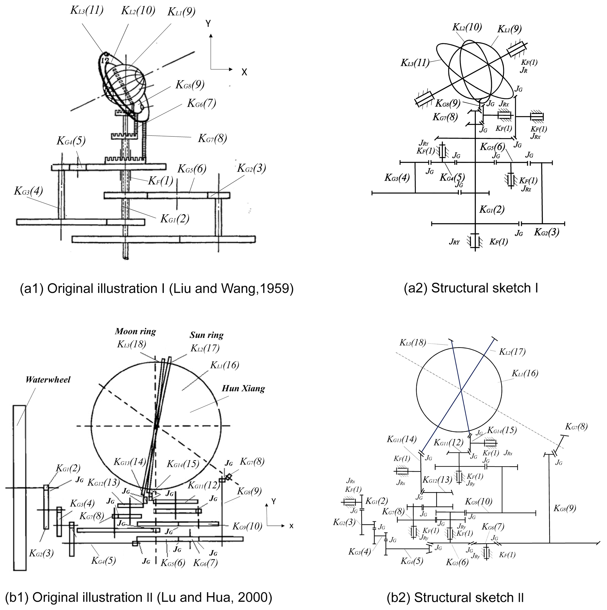
Figure 1Gear drive systems of the water-powered celestial globe by Liu Xian-Zhou, namely (a) type I (Liu and Wang, 1959) and (b) type II (Lu and Hua, 2000).
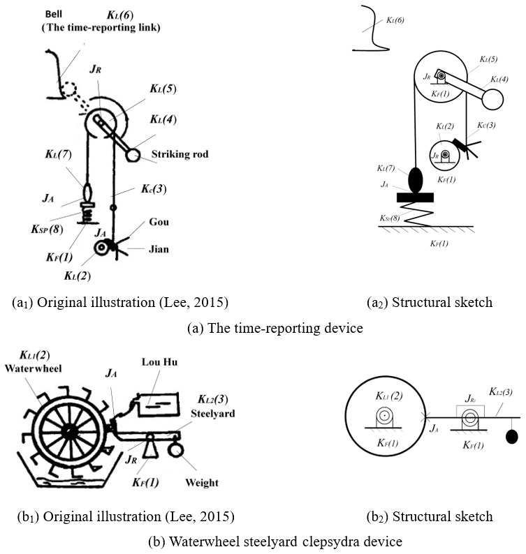
Figure 2Reconstruction concepts of the water-powered celestial globe by Li Zhichao (Liu, 2015). (a) The time-reporting device's original drawing and schematic diagram. (b) The waterwheel and the steelyard original drawing and schematic diagram.
The available historical records on the mechanical structure of the water-powered celestial globe are brief and simple. In order to use the methodology for the reconstruction design of lost ancient machinery, it is thus necessary to revisit relevant historical documents and develop design specifications for its systematic reconstruction.
2.1 Historical archives
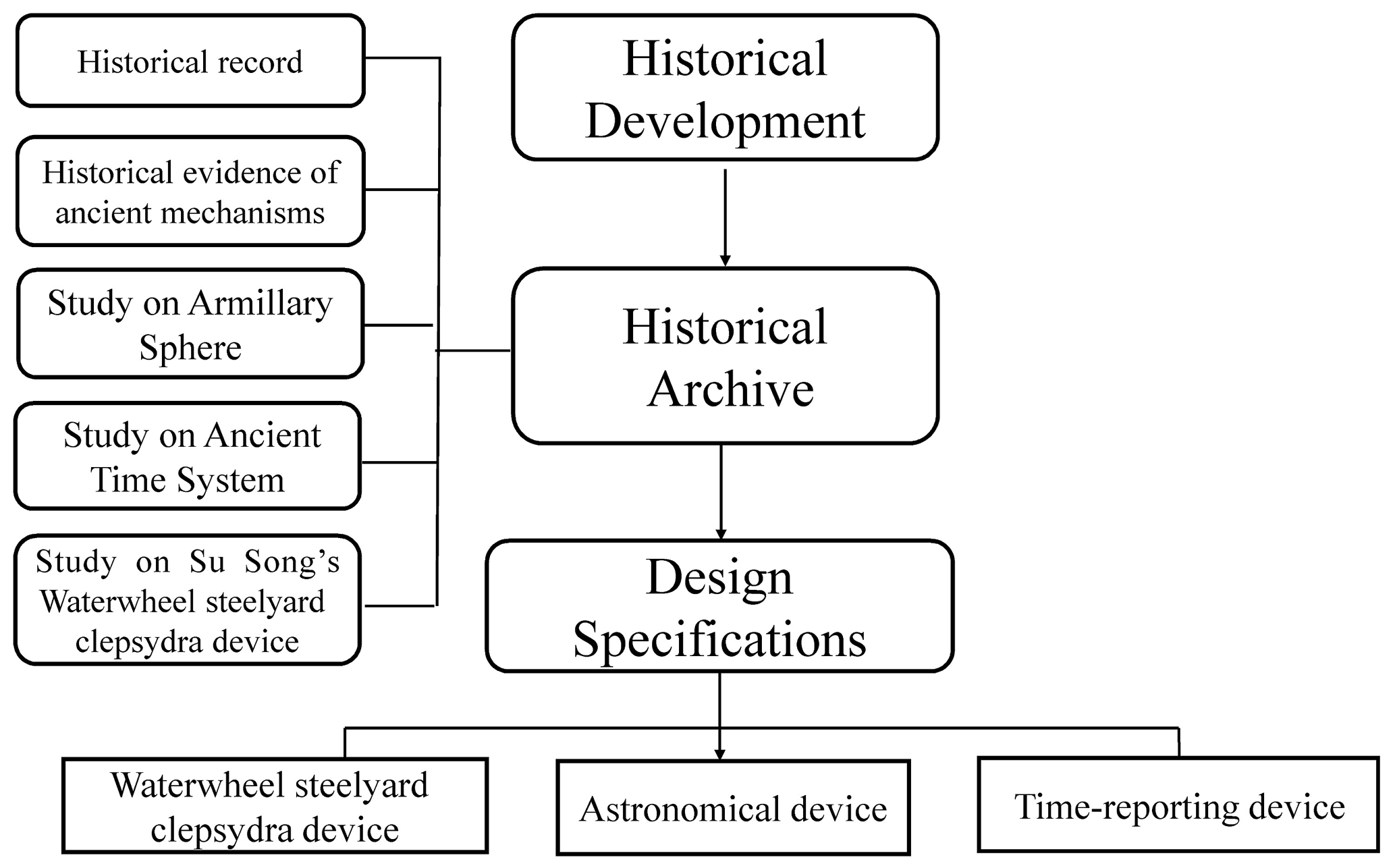
Historical archives include historical records, historical evidence of the mechanisms, armillary spheres, systems of time reporting, and the waterwheel steelyard clepsydra. In addition, researches on the waterwheel steelyard clepsydra developed by Su Song were used to fill gaps in historical records to arrive at a better understanding of the internal mechanism and operation principle of the device. The use of historical archives to develop design specifications is shown in Fig. 3.
2.1.1 Historical records
The Volume on Astronomy in The Old Books of Tang contained records related to the water-powered celestial globe (Liu et al., 1981).
Tang Emperor Xuanzong issued an order to monk I-Hsing, Liang Lingzan, and many others who knew astrology. The order was to change the size of the existing celestial globe (hun xiang) and build a new celestial globe using a copper sphere. On the celestial globe there are to be carvings depicting constellations, the Equator, and the 365 degrees of astrology. Movement of the celestial globe is driven by a waterwheel, and the celestial globe makes a complete rotation in one day and night. This celestial globe will have two rings, with the Sun and Moon pattern shown on each of the ring. When the celestial globe turns one complete cycle to the west every day, the Sun ring travels eastward by one degree, and the Moon ring travels 13– degrees. After slightly more than twenty-nine rotations of the Moon ring, the Sun ring and the Moon ring will meet, and the entre celestial globe will have completed 365 revolutions, while the Sun ring will have completed one revolution. Using the wooden cabinet as the ground level, half of the celestial globe will be exposed above the ground level. The celestial globe moves day and night, and on the first and fifteenth day of the lunar calendar, the speed of the Moon ring movement will be consistent with the movement of celestial bodies. On the wooden cabinet, there will be two small wooden men; one has a drum while the other has a bell in front of it. To report time, one of the wooden man beats the drum on every ke, and on every hour, the other wooden man strikes the bell. A hook rod and metal rod is installed on the wheel axle for triggering the time-reporting mechanism. In addition, the waterwheel will be equipped with a start–stop device and a device similar to a lock. These two devices are interconnected.
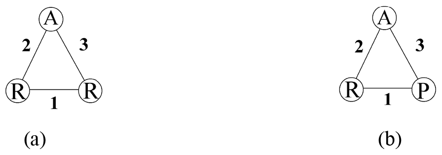
The above description shows that the water-powered celestial globe was an astronomical clock with a time-reporting device, and the waterwheel was its main driving element. Time-reporting was achieved in the following two ways: a wooden man beats a drum on every ke, while another wooden man strikes a bell on every hour. The two wooden men were triggered by a hook-shaped rod and a metal rod on the waterwheel shaft (Xu, 1963). It can be seen that the hook-shaped rod and the latch-shaped metal rod were connected, respectively, to the drum and strike lever of the time-reporting device with a cam joint (A) and a prismatic joint (P). This is the first design specification.
Because the waterwheel had a timing function, the water-powered celestial globe must have a waterwheel steelyard clepsydra. This device consisted of a switch, an ancient lock mechanism, and a linkage device (Liu et al., 1981; Xu, 1963). Referring to Su Song's waterwheel steelyard clepsydra, this switch must be a lower balancing lever mechanism, while the lock mechanism and linkage device must function as an escapement mechanism. The lock mechanism was used to control the rotation of the waterwheel. It acted like a door bolt sliding on the inner surface of the door panel to control the motion of the waterwheel. For this reason, the brake link that controlled the operation of the waterwheel was connected to the ground link through a prismatic joint (P). In addition, from the illustration in New Design for an Armillary Sphere and Celestial Globe (Hu, 1997), it is known that an upper locking mechanism was used to stop the movement of the waterwheel. This is the second design specification.
The astronomical device was composed of a celestial globe, Sun ring, Moon ring, and transmission mechanism. The direction of the movement of the Sun and the Moon rings was opposite to that of the celestial globe. This is the third design specification. Because available historical records are short and simple, it is necessary to compile the design specifications from historical archives, which include historical evidence of ancient mechanisms, the armillary sphere, the system of time reporting, and research on Su Song's waterwheel steelyard clepsydra. Explanations follow.
2.1.2 Historical evidence of ancient mechanisms
The following is a review of the historical records of the waterwheel, gears and ratchets, and linkage mechanisms. From the review, design specifications were formulated, which were then used as a reference for the design of computer graphics for 3D reconstruction models, while taking into account the available technology at the time.
- a.
Waterwheel
The earliest waterwheel in ancient China was known as shui dui. It was also the most typical cam mechanism and was widely used in the Western Han Dynasty (202 BCE–220 CE; Yan, 2007; Lu and Hua, 2000). During the Eastern Jin Dynasty (317–420 CE), its mechanism became more complicated, and the waterwheel evolved to become vertically standing. Lu Jingyan believed that the waterwheel in the water-powered celestial globe was a vertical waterwheel (Lu and Hua, 2000), and Joseph Needham (1900–1995 CE) believed that using wooden men to report time was a design derived from the water transfer mechanism developed by Ma Jun (200–265 CE) from the kingdom of Wei during the Three Kingdoms Period (Liu and Wang, 1959). All these serve as additional explanation for the first design specification.
- b.
Gear and ratchet
In ancient China, gears were mainly used for power and motion transmission. According to the illustration in New Design for an Armillary Sphere and Celestial Globe, the Equator in the water-powered armillary sphere and celestial globe consisted of a gear system (Fig. 4). It was used as transmission for the astronomical device. This is the fourth design specification.
From 1954 to 1984, many gears from the Han Dynasty were unearthed in China, some of which have a shape similar to a ratchet (Chen, 2004). In 1973, a set of ratchet mechanisms was unearthed at the site of the city of Dong Zhuo in Luoyang, and it can thus be deduced that ratchets were widely used during ancient times (Nie, 2012). The ratchet mechanism, which was used to achieve one-way braking, can be used as an escapement regulator to control the one-way intermittent movement of the waterwheel steelyard clepsydra. This is the fifth design specification.
- c.
Linkage mechanism
The linkage mechanism consisted of linking rods, and its main functions were to convert motion types and directions, synchronize the different state of motions, align the positions of rigid bodies, and determine motion paths (Yan, 2016). During the period of Zhuang Zhou (369–286 BCE), there were historical records of the use of linkage mechanisms in ancient China (Yan, 2007). In the records of New Design for an Armillary Sphere and Celestial Globe, the upper balance mechanism (tianheng) in the waterwheel steelyard clepsydra was a linkage mechanism. For this reason, the linkage mechanism can be used to design the internal mechanism of the waterwheel steelyard clepsydra. This is the sixth design specification.
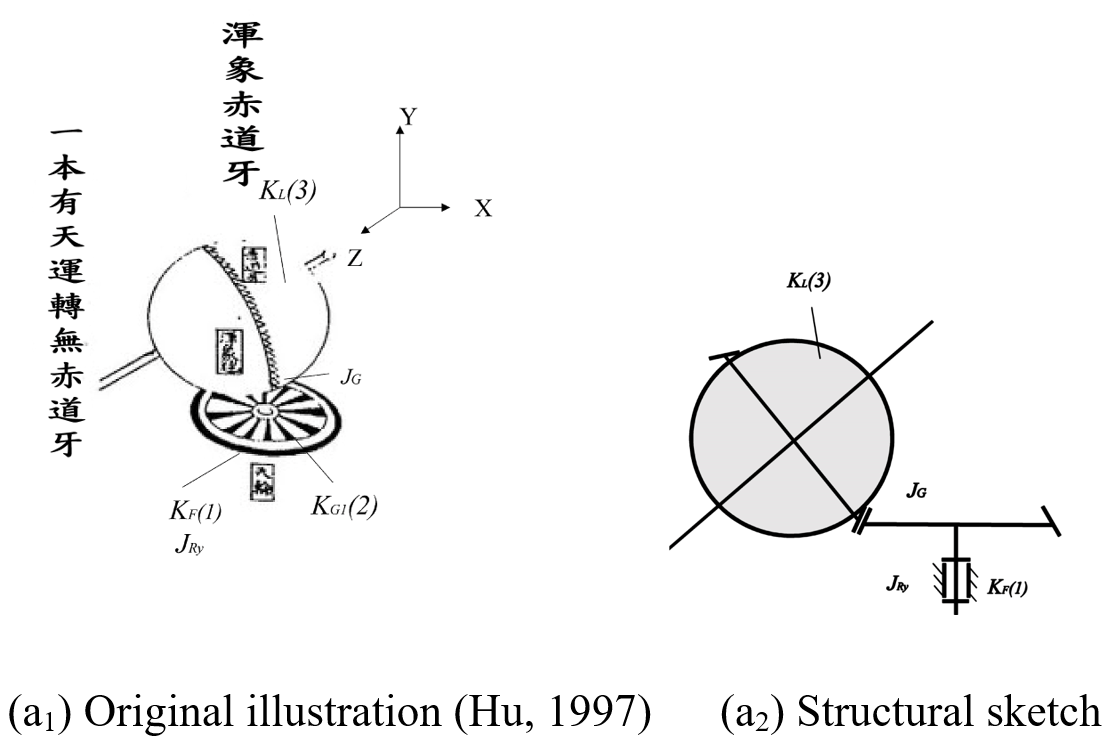
Figure 4Su Song's celestial globe transmission system (Hu, 1997).
2.1.3 Armillary sphere (hun yi)
Before the Tang Dynasty (618–907 CE), historical records only contained the armillary sphere (hun yi) built by Kong Ting during the Former Zhao Dynasty (319–351 CE). During the Tang Dynasty, Li Chunfeng (602–670 CE) built an armillary sphere with three rings, namely the liuhe yi, sanchen yi, and siyou yi (Pan, 2005). According to records by the monk I-Hsing and Liang Lingzan (Liu et al., 1981), as well as Li Chunfeng's records on the sanchen yi mechanism, the Sun and Moon double rings in the water-powered celestial globe should be independent of each other. This is the seventh design specification.
2.1.4 Time law
In ancient China, the bai ke system of measuring time divided a day into ke (100 equal units), while the shichen system divided a day into chen (12 dual hours). Because 100 is indivisible by 12, during the monk I-Hsing (683–727 CE) divided 1 chen into 5 ke, which resulted in 60 ke in 1 d. This process overcame the incompatibility between the bai ke and shi chen systems of time keeping (Cao, 1986). This process can be used as the design of the time-reporting system to determine the number of water-receiving scoops in the waterwheel. This is the eighth design specification.
2.1.5 Waterwheel steelyard clepsydra device
The waterwheel steelyard clepsydra built by Wang Fu (1079–1126 CE), Su Song, and Zhang Sixun during the Northern Song Dynasty (960–1127 CE) was believed to have been modeled after that built by the monk I-Hsing. Therefore, research on the Su Song waterwheel steelyard clepsydra can help us to understand the structure of the waterwheel steelyard clepsydra in the water-powered celestial globe. Su Song's waterwheel steelyard clepsydra was composed of a steelyard clepsydra and an escapement mechanism, as seen in Fig. 5 (Lin, 2001; Hsiao and Yan, 2014).
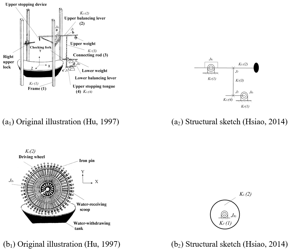
Figure 5Upper stopping device and driving wheel of Su Song's waterwheel steelyard clepsydra (Hu, 1997; Hsiao, 2014).
Tsung-yi Lin proposed a kinematic model for Su Song's waterwheel steelyard clepsydra, which can be used as a reference to design the relative positions of the internal components of the water-powered celestial globe (Lin, 2001), as seen in Fig. 6.

Figure 6Kinematic model of Su Song's waterwheel steelyard clepsydra (Lin, 2001).
In Su Song's upper balancing lever mechanism, a connecting rod transmits the force of the upper stopping tongue. The force is amplified by the upper balancing lever to swing the upper lock and upper stopping device to control the movement of the driving wheel. Therefore, the waterwheel steelyard clepsydra must consist of a transmission link and a swing link. This is the ninth design specification.
2.2 Design specifications
Summarizing the above, there are nine design specifications for the water-powered celestial globe.
-
There are two rods used for time-reporting that are arranged on the shaft of the waterwheel. They are connected by a cam joint (A) and prismatic joint (P).
-
The escapement regulator has a switch, a transmission link, and a brake link. The brake link is similar to an ancient door bolt, which slid on the inner surface of the door to stop the waterwheel. Alternatively, there is an upper locking mechanism to stop the operation of the waterwheel.
-
The astronomical device is composed of a celestial globe, Sun ring, Moon ring, and transmission system. The direction of the Sun–Moon double ring is opposite to that of the celestial globe.
-
The transmission system is a gear mechanism.
-
The ratchet mechanism is used for one-way braking, and it can be used as an escapement in the waterwheel steelyard clepsydra.
-
The linkage mechanism can be used as the internal mechanism of the escapement regulator.
-
The Sun and Moon rings of the astronomical device should be separate and independent.
-
In the design of the time-reporting device, 1 h is 5 ke.
-
The linkage mechanism of the waterwheel steelyard clepsydra is composed of a transmission link and a swing link.
Among the nine design specifications, nos. 2, 5, 6, and 9 relate to the waterwheel steelyard clepsydra, nos. 1 and 8 related to the time-reporting device, while nos. 3, 4, and 7 relate to the astronomical device.
Based on the above design specifications, the following sections describe the functions, number of members, types of joints, and degrees of freedom of movement of the waterwheel steelyard clepsydra, time-reporting device, and astronomical device.
3.1 Waterwheel steelyard clepsydra
Based on design specification 2, the brake link and transmission link can be configured in the following two ways:
- 1.
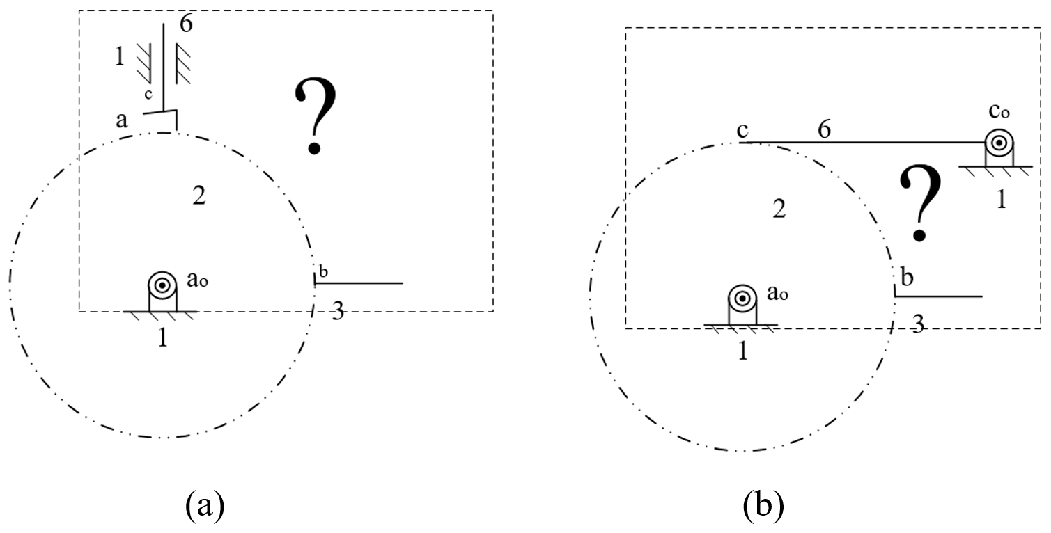
Model I – by assuming that the brake link (rod 6) is connected to the ground link through a prismatic joint (P) to stop the waterwheel and generate intermittent motion (Fig. 7a), or by assuming that there is an upper stopping device to stop the waterwheel (Fig. 7b).
- 2.
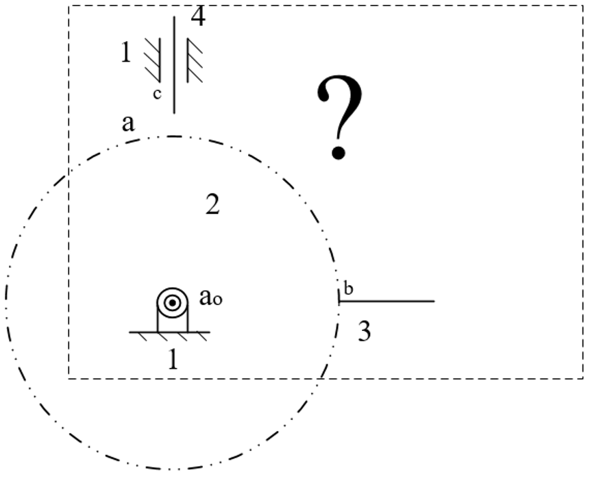
Model II – by assuming that the transmission link is connected to the ground link through a prismatic joint (P), so that the brake link can stop the waterwheel (Fig. 8).
In both models I and II, the design of the internal mechanism of the waterwheel steelyard clepsydra must include a ground link, a waterwheel link, a lower balancing lever, a transmission link, a swing link, and a brake link. The internal mechanism should at least be a six-member, eight-joint planar mechanism. To achieve its design functions, the mechanism can be designed to have six revolving joints (R), one cam joint (A), and one upper stopping device (tianguan) joint (T). Alternatively, the design could include five revolving joints (R) and one prismatic joint (P), one cam joint (A), and one upper stopping device joint (T). This forms a planar mechanism with one degree of freedom, which is the simplest mechanism to meet these design specifications, and the function of each link is explained as follows.
-
Ground link
This is the frame that is connected to the brake link, the swing link, the transmission link, and the lower balancing lever rod.
-
Waterwheel link
It is mainly used to fix the weight of the water, causing the waterwheel to generate instant torque.
-
Lower balancing lever rod
It is used to compare weights, and the waterwheel thus becomes a sensor to detect the weight of the water at any given time. When the lower balancing lever rod is out of balance, the force of the transmission link is transmitted to the swing link or the brake link to control the movement of the waterwheel.
-
Transmission link
It is mainly used as the power transmission of the lower balancing lever rod, so that the swing link drives the brake link to control the operation of the waterwheel.
-
Swing link
The swing link transfers power from the transmission link to the brake link to control the movement of the waterwheel. It also serves as a linkage link for the movement of the various mechanism between the links.
-
Brake link
Its main function is to stop the waterwheel to produce periodic movements.
3.2 The time-reporting device
The time-reporting device is believed to be a waterwheel mechanism with a swing link on the waterwheel that triggered the time-reporting link to report time. This mechanism is believed to be at least a three-member, three-joint planar mechanism, which included a ground link, a striking rod, and a time-reporting link. Based on the design function requirements, the design can consist of either two revolving joints (R) and one cam joint (A) or one revolving joint (R), one prismatic joint (P), and one cam joint (A), both of which are plane mechanisms with 1 degree of freedom. This is the simplest mechanism design for design specification 1, and the function of each link is explained as follows:
-
Ground link
The frame is connected to the striking rod and the time-reporting link.
-
Striking rod
It is mainly used to strike the time-reporting link to keep time.
-
Time-reporting link
It is mainly used for time reporting.
3.3 The astronomical device
Based on design specifications 3, 4, and 7, the astronomical device should include a ground link, a celestial globe link, a Sun link, a Moon link, and a transmission mechanism. A simple transmission mechanism includes a driving link, intermediate shaft links, and a driven link. The intermediate shaft links are used to control the movement of the Sun link, the Moon link, and the celestial globe link. Since the number of intermediate shaft links are unknown, this study assumes that there are two intermediate shaft links, which are the intermediate shaft link and the idler link. For this reason, the mechanism of the astronomical device should actually include a ground link, a driving link, an intermediate shaft link, an idler link, a celestial globe link (driven link), a Sun link, and a Moon link. In all, it should be at least a seven-member, 11 joint planar mechanism. Based on functional requirements, the design can consist of a planar mechanism with six revolving joints (R) and five gear joints (G), and have 1 degree of freedom. This is the simplest mechanism design for design specifications 3, 4, and 7. The function of each link is explained as follows:
-
Ground link
The ground link acts as a frame and is connected to the driving link, the intermediate wheel link, the idler link, and the celestial globe link.
-
Driving link
Its function is to drive the intermediate wheel link, idler link, and celestial globe link to rotate the wheel train using power input from the waterwheel.
-
Intermediate shaft link
Its function is to change the rotation speed and direction of the Sun link, Moon link, and driven link.
-
Idler link
Its function is to change the rotation speed and direction of the Sun link, Moon link, and driven link.
-
Celestial globe link
It is a driven link, and its function is to simulate the movement of celestial bodies.
-
Sun link
Its function is to simulate the movement of the Sun link on the ecliptic plane.
-
Moon link
Its function is to simulate the movement of the Moon link on the lunar orbit.
The design methodology for the reconstruction of lost ancient machinery is shown in Fig. 9. The methodology involves three procedures, namely developing the generalized kinematic chains, developing the specialized chains, and reconstructing the design. The procedures are explained as follows.
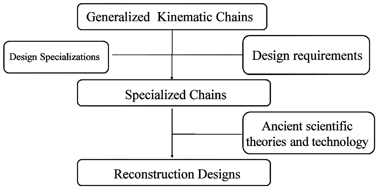
Figure 9Process of reconstruction design (Yan, 2007).
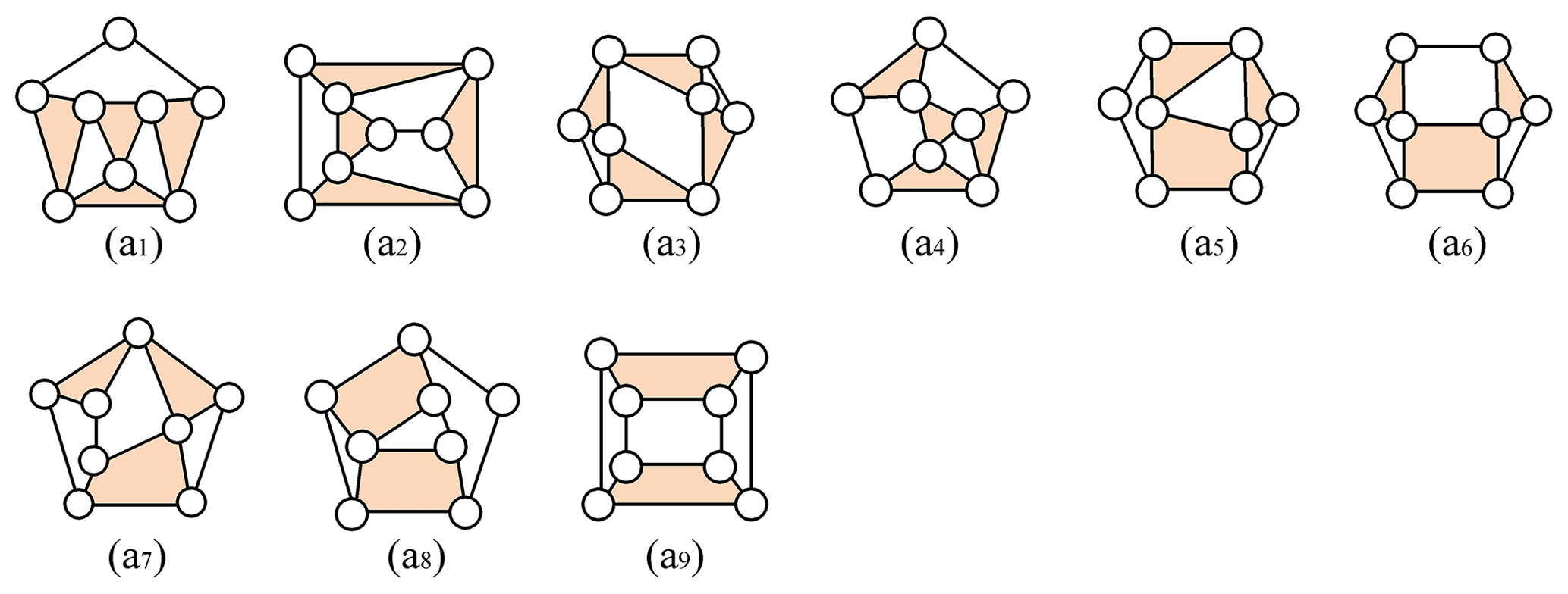
Figure 10Generalized chains for the (6, 8) atlas (Yan, 1998).
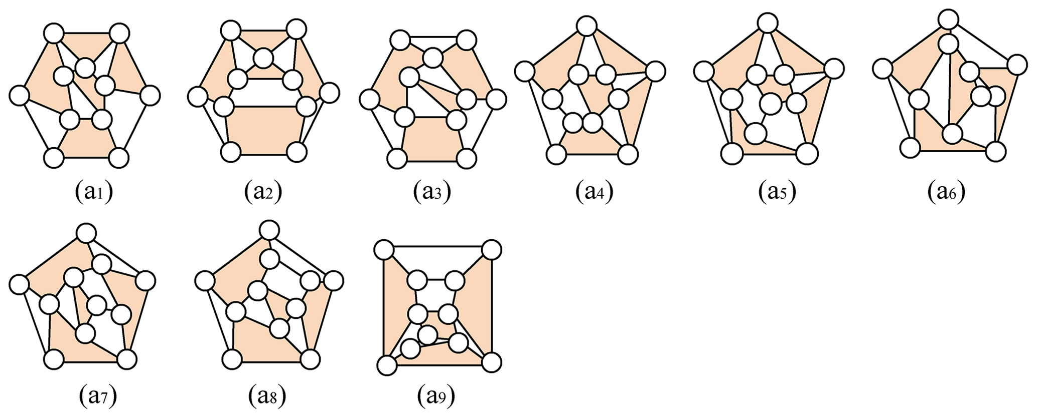
Figure 11Some generalized chains for the (7, 11) atlas (Yan, 1998).
4.1 Generalized kinematic chains
Based on the design specifications, the corresponding generalized kinematic chains are obtained. Using number synthesis, the atlas of generalized kinematic chains with the required number of links and joints can be obtained (Yan, 1988). Figure 10 show the atlas for the waterwheel steelyard clepsydra and time-reporting device.
Based on the design specifications of the astronomical device, the celestial globe link (driven link) should be a quaternary link, the Sun link and the Moon link are binary links, and the Sun and Moon links must be connected to the celestial globe link with a revolving joint (R). There are nine atlases of (7, 11) generalized chains that meet this condition, as shown in Fig. 11.
4.2 Specialized chains
To develop the specialized chains (Yan, 2007), the generalized kinematic chains and design specifications are used to determine the required links and joints.
4.3 Reconstruction designs
Based on the movement and functional requirements of the mechanism, the abstract icons developed during the specialization process are converted into corresponding equivalent mechanism diagrams, where all feasible mechanism atlases that meet the ancient technological level can be obtained.
The following three examples illustrate the proposed process of the reconstruction design.
5.1 Example 1: reconstruction design for the waterwheel steelyard clepsydra
After obtaining the atlas of the generalized kinematic chains, all feasible specialized chains can be obtained using the following steps:
-
For each generalized kinematic chain, identify the ground link.
-
For each case obtained in step 1, find the waterwheel link.
-
For each case obtained in step 2, find the lower balancing link.
-
For each case obtained in step 3, find the transmission link.
-
For each case obtained in step 4, find the swing link.
-
For each case obtained in step 5, find the brake link.
When performing the above steps, the following design requirements must be observed.
Ground link (link G)
Based on the functional requirements, the ground link should be a multi-joint link.
Waterwheel link (link 2)
The waterwheel link is controlled by the control link and the periodic power input, and it is connected to the lower balancing link with a cam joint (A). Due to its functional requirements, the upper stopping device (tianguan) joint (T) or the cam joint (A) can be connected to the brake link. The waterwheel link in this instance is a ternary link.
Lower balancing link (link 3)
The function of the lower balancing link is to generate periodic movement and transfer power to the waterwheel link. Based on the functional requirements of the design, the lower balancing link is a multi-joint link.
Transmission link (link 4)
The transmission link connects to the brake link, the lower balancing link, and the swing link through a revolving joint (R). Based on the requirements of the actuation design, the transmission link should be connected to the ground link through a prismatic joint (P). The transmission link then becomes either a binary link or a ternary link.
Swing link (link 5)
The swing link enables the connecting link to change the direction of movement. It is connected to a revolving joint (R), along with the transmission link and the brake link. Based on the requirements of the actuation design, the swing link is either a binary link or a ternary link.
Brake link (link 6)
Based on the requirements of the actuation design, the brake link is connected to the ground link either through a prismatic joint (P) or a revolving joint (R). It can be a binary link or a ternary link.
The specialization process will result in two models, i.e., model I and model II. They are explained as follows.
5.1.1 Example 1(a): model I
There are nine generalized chains with six links and eight joints, as shown in Fig. 10. All possible configurations are identified through the following steps.
Ground link (link G)
The ground link (link G) is a multiple link connected to the frame. The ground link G can be explained as follows:
-
For the generalized chain shown in Fig. 10a1, assigning ground link G generated three results, as shown in Fig. 12a1–a3.
-
For the generalized chain shown in Fig. 10a2, assigning ground link G generated two results, as shown in Fig. 12b1–b2.
-
For the generalized chain shown in Fig. 10a3, assigning ground link G generated one result, as shown in Fig. 12c1.
-
For the generalized chain shown in Fig. 10a4, assigning ground link G generated three results, as shown in Fig. 12d1–d3.
-
For the generalized chain shown in Fig. 10a5, assigning ground link G generated three results, as shown in Fig. 12e1–e3.
-
For the generalized chain shown in Fig. 10a6, assigning ground link G generated two results, as shown in Fig. 12f1–f2.
-
For the generalized chain shown in Fig. 10a7, assigning ground link G generated three results, as shown in Fig. 12g1–g3.
-
For the generalized chain shown in Fig. 10a8, assigning ground link G generated one result, as shown in Fig. 12h1.
-
For the generalized chain shown in Fig. 10a9, assigning ground link G generated one result, as shown in Fig. 12i1.
Therefore, assigning ground link G resulted in 19 specialized chains, as shown in Fig. 12.

Figure 12Specialized chains atlas of (6, 8) with assigned ground link.
Waterwheel link (link 2) and brake link (link 6)
The waterwheel link must be a ternary link, and the brake link must be a multiple link. Based on model I, the waterwheel link is connected to the ground link G through a revolving joint (R). The brake link is connected to the ground link G through a prismatic joint (P), and the brake link is connected to the waterwheel link through the upper stopping device (tianguan) joint (T). The resulting motion of the waterwheel link 2 and the brake link 6 can be explained as follows:
-
For the case shown in Fig. 12a1, assigning waterwheel link 2 and brake link 6 generated one result, as shown in Fig. 13a1.
-
For the case shown in Fig. 12a2, assigning waterwheel link 2 and brake link 6 generated one result, as shown in Fig. 13a2.
-
For the case shown in Fig. 12d1, assigning waterwheel link 2 and brake link 6 generated two results, as shown in Fig. 13b1–b2.
-
For the case shown in Fig. 12d2, assigning waterwheel link 2 and brake link 6 generated one result, as shown in Fig. 13b3.
-
For the case shown in Fig. 12e1, assigning waterwheel link 2 and brake link 6 generated one result, as shown in Fig. 13c1.
-
For the case shown in Fig. 12e2, assigning waterwheel link 2 and brake link 6 generated one result, as shown in Fig. 13c2.
-
For the case shown in Fig. 12e3, assigning waterwheel link 2 and brake link 6 generated two results, as shown in Fig. 13c3–c4.
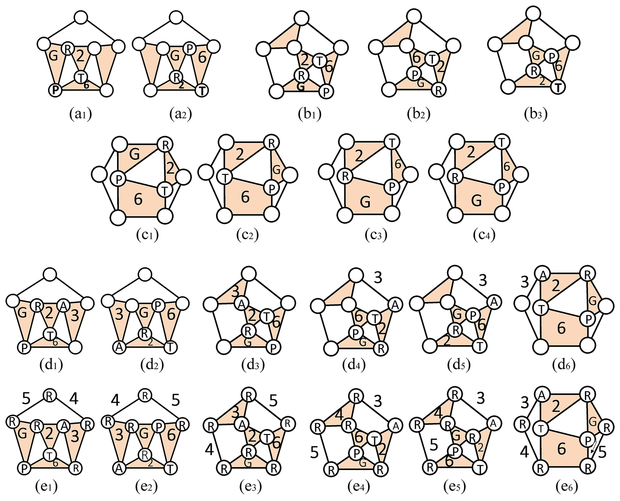
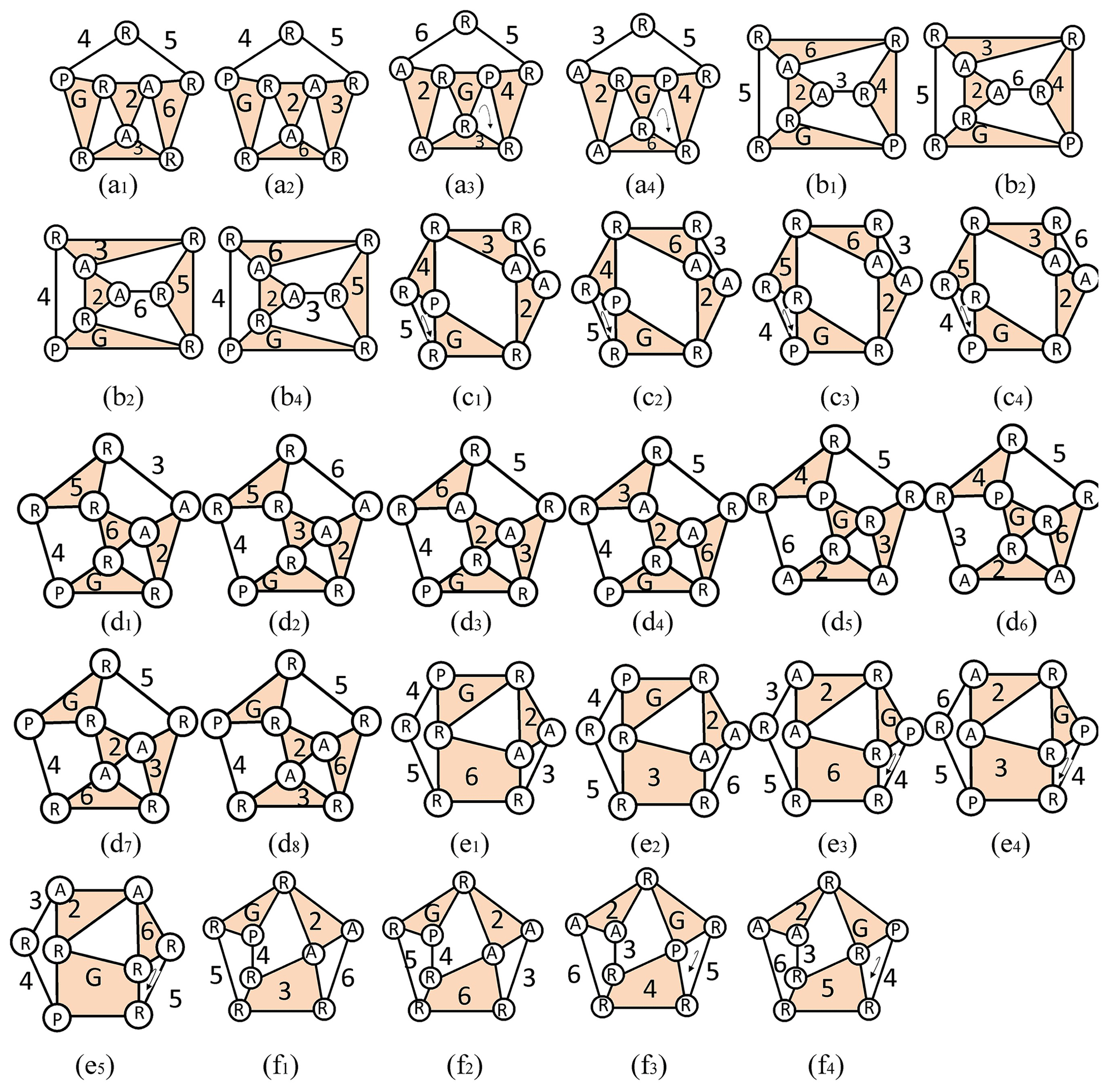
Therefore, assigning waterwheel link 2 and brake link 6 resulted in nine specialized chains, as shown in Fig. 13a1–c4.
Lower balancing link (link 3)
The lower balancing link can either be a binary link or a ternary link, and it is connected to the waterwheel link through a cam joint (A). Based on the design requirements, the lower balancing link is also connected to the ground link through a revolving joint (R). Accordingly, the lower balancing link 3 can be configured as follows:
-
For the case shown in Fig. 13a1, assigning the lower balancing link 3 generated one result, as shown in Fig. 13d1.
-
For the case shown in Fig. 13a2, assigning the lower balancing link 3 generated one result, as shown in Fig. 13d2.
-
For the case shown in Fig. 13b1, assigning the lower balancing link 3 generated one result, as shown in Fig. 13d3.
-
For the case shown in Fig. 13b2, assigning the lower balancing link 3 generated one result, as shown in Fig. 13d4.
-
For the case shown in Fig. 13b3, assigning the lower balancing link 3 generated one result, as shown in Fig. 13d5.
-
For the case shown in Fig. 13c2, assigning the lower balancing link 3 generated one result, as shown in Fig. 13d6.
Therefore, assigning the lower balancing link 3 resulted in six specialized chains, as shown in Fig. 13d1–d6.
Transmission link (link 4) and swing link (link 6)
The transmission link and the swing link are part of the transmission mechanism in the waterwheel steelyard clepsydra. Based on functional requirements, they are connected to the lower balancing link 3 and the ground link G thorough a revolving joint (R). Accordingly, assigning transmission link 4 and swing link 6 resulted in the following:
-
For the case shown in Fig. 13d1, assigning transmission link 4 and swing link 6 generated one result, as shown in Fig. 13e1.
-
For the case shown in Fig. 13d2, assigning transmission link 4 and swing link 6 generated one result, as shown in Fig. 13e2.
-
For the case shown in Fig. 13d3, assigning transmission link 4 and swing link 6 generated one result, as shown in Fig. 13e3.
-
For the case shown in Fig. 13d4, assigning transmission link 4 and swing link 6 generated one result, as shown in Fig. 13e4.
-
For the case shown in Fig. 13d5, assigning transmission link 4 and swing link 6 generated one result, as shown in Fig. 13e5.
-
For the case shown in Fig. 13d6, assigning transmission link 4 and swing link 6 generated one result, as shown in Fig. 13e6.
Therefore, assigning the transmission link (link 4) and swing link (link 6) resulted in six specialized chains, as shown in Fig. 13e1–e6. However, because Fig. 13e6 shows a three-bar loop formed by the joints R–R–R, which results in a rigid chain, it is not a feasible mechanism.
5.1.2 Reconstruction design – model I
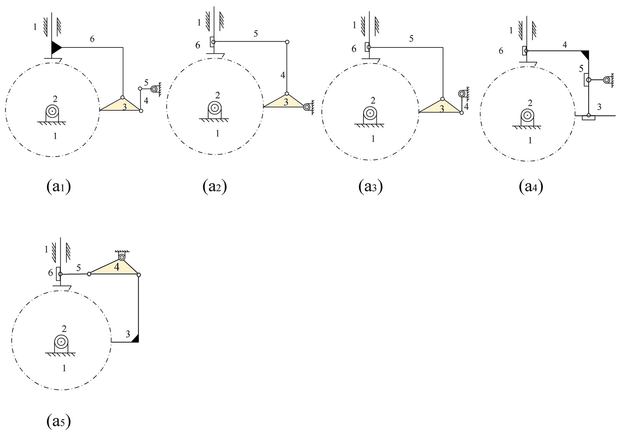
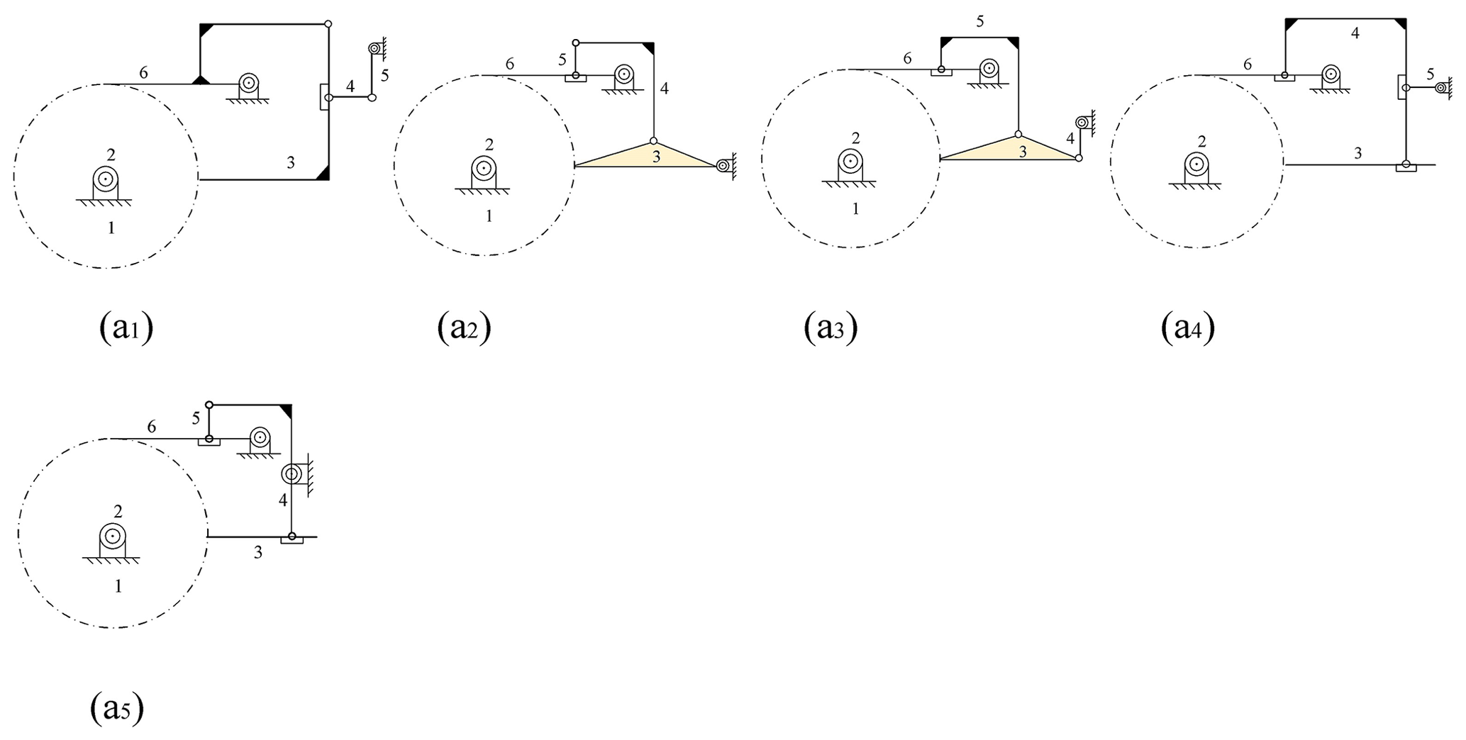
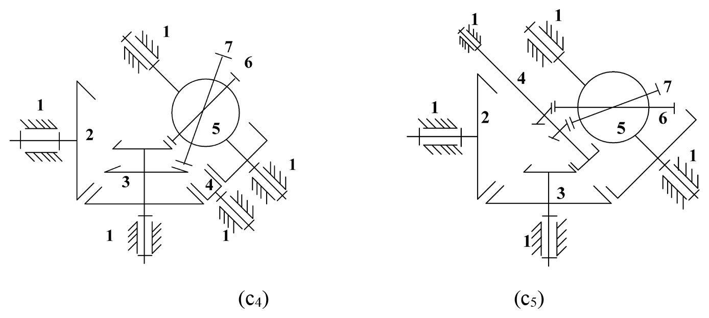
Based on the functional requirements of model I, the specialized chain atlas of model I obtained in Fig. 13e1–e6 can be divided into two cases, i.e., case (a) and case (b). For the six feasible specialized chains in Fig. 13e1–e5, their corresponding interior mechanisms are represented in Figs. 14 and 15.
5.1.3 Example 1(b): model II
Taking into account the functional requirements of model II, link 6 and link 2 were replaced, respectively, by a pawl and a ratchet.
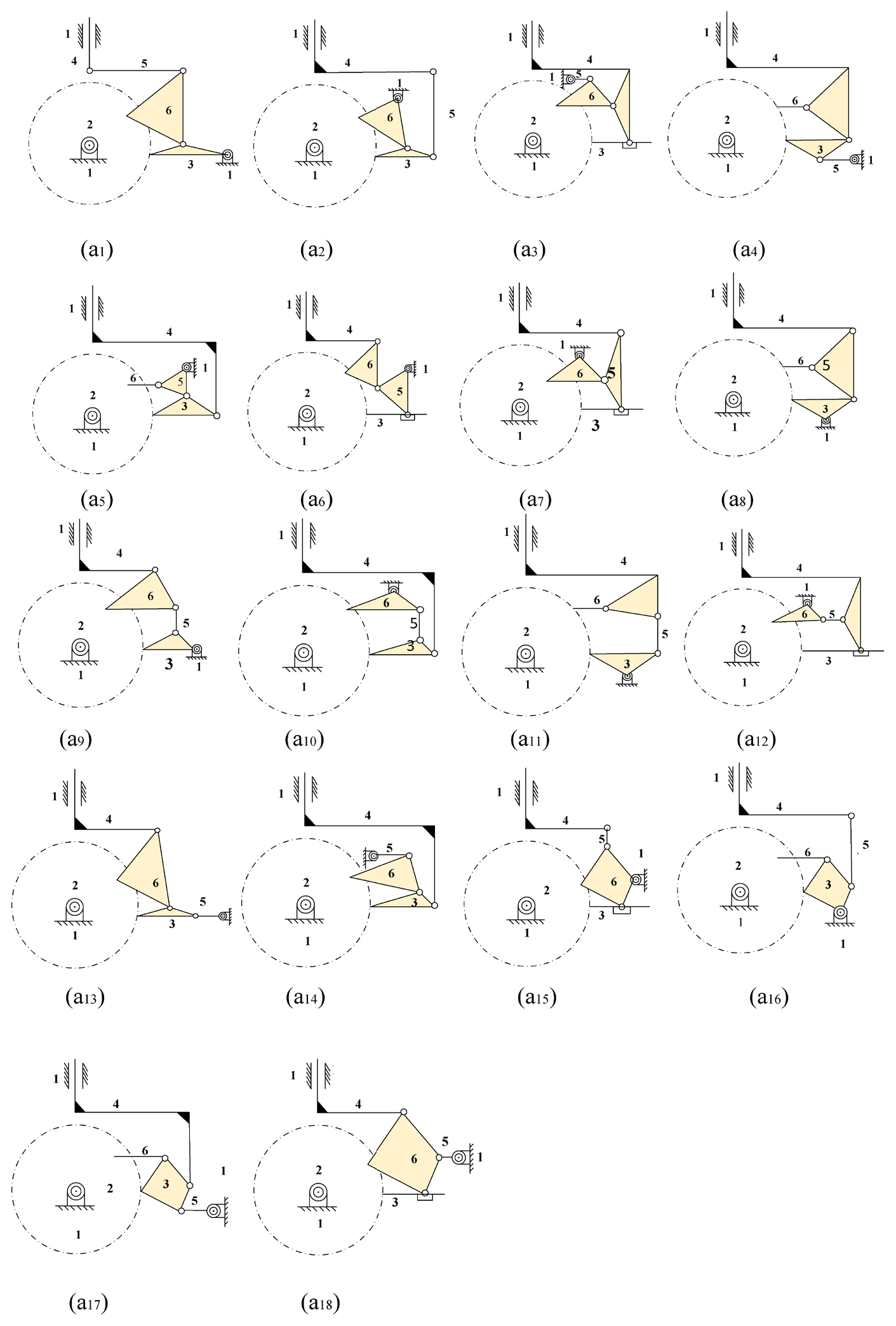
Figure 16a1–f4 represent the atlas of the specialization chains for model II. Figure 16a3, a4, c1, c2, c3, c4, e3, e4, e5, f3, and f4 show three-bar loops formed either by joints R–R–R or R–R–P, which result in a rigid chain. As a result, they are inoperative, as shown in Fig. 17. Since the internal devices in Fig. 17a3, a5, and a12 have defects that prevent the internal devices from generating motion transmission, there are 15 feasible designs for model II.
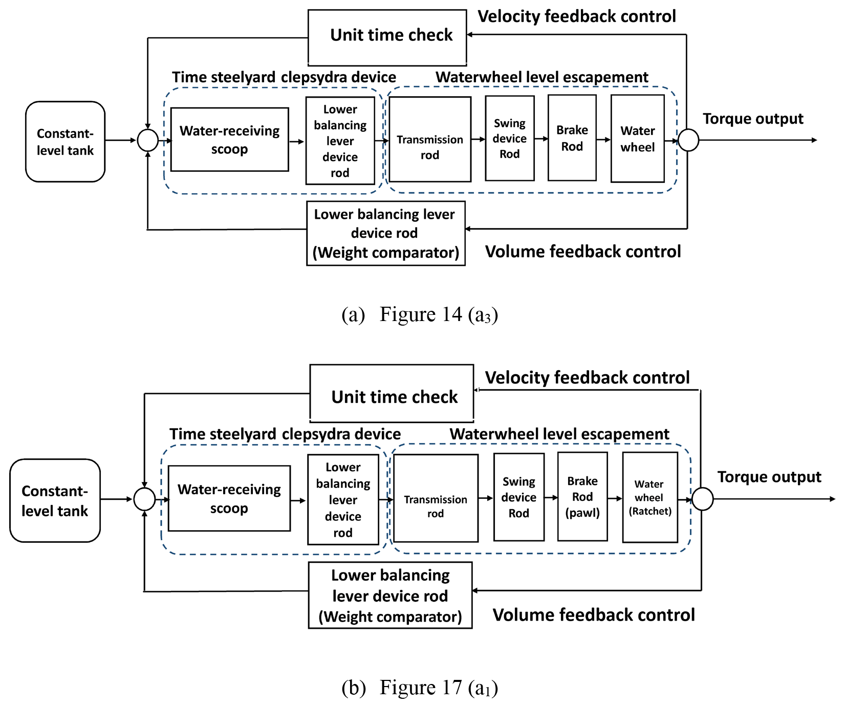
5.1.4 Kinematic analysis of the waterwheel steelyard clepsydra
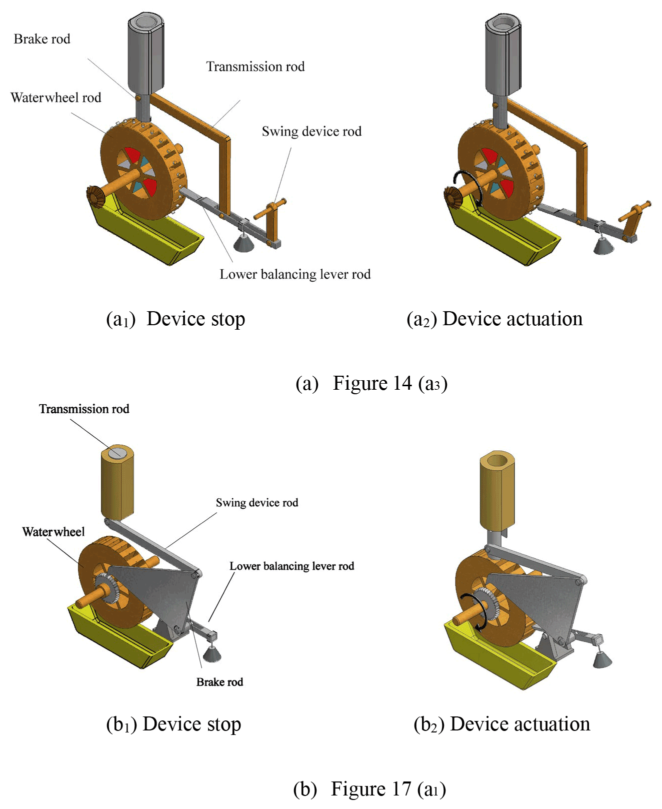
The following discussions use Fig. 14a3 in model I and Fig. 17a1 in model II to illustrate the operation of the steelyard clepsydra in Fig. 18. The waterwheel steelyard clepsydra uses a dual-feedback control system, namely water volume feedback control and water velocity feedback control. The water volume feedback control is a force feedback control that uses the lower balancing lever as a weight comparator to determine whether the brake link has enough power to stop the waterwheel from running and whether the waterwheel produces enough torque to drive the time-reporting device and the astronomical device. On the other hand, the water velocity feedback control adjusts the water flow rate to the water-receiving scoop to control the periodic movement of the waterwheel steelyard clepsydra.
Consequently, the steelyard clepsydra is able to maintain precise timing and periodic movements, as shown in Fig. 19.
5.2 Example 2: reconstruction design for the time-reporting device
After obtaining the generalized chain atlas of the time-reporting device, the following steps are used to obtain all possible specialized chain atlases.
-
For each generalized chain, identify the ground link.
-
For each case obtained in step 1, identify the striking link.
-
For each case obtained in step 2, identify the time-reporting link.
When performing the above steps, the following design requirements must be observed.
Ground link (link 1)
This is the frame and a binary link.
The striking link (link 2)
It is connected to the time-reporting link through the cam joint (A). It is a binary link.
The time-reporting link (link 3)
Because the time-reporting link is shaped differently, it is connected to the ground link through the revolving joint (R) and prismatic joint (P). The time-reporting link is a binary link.
After the specialization process, the specialization atlas of the time-reporting device can be obtained, as shown in Fig. 20.
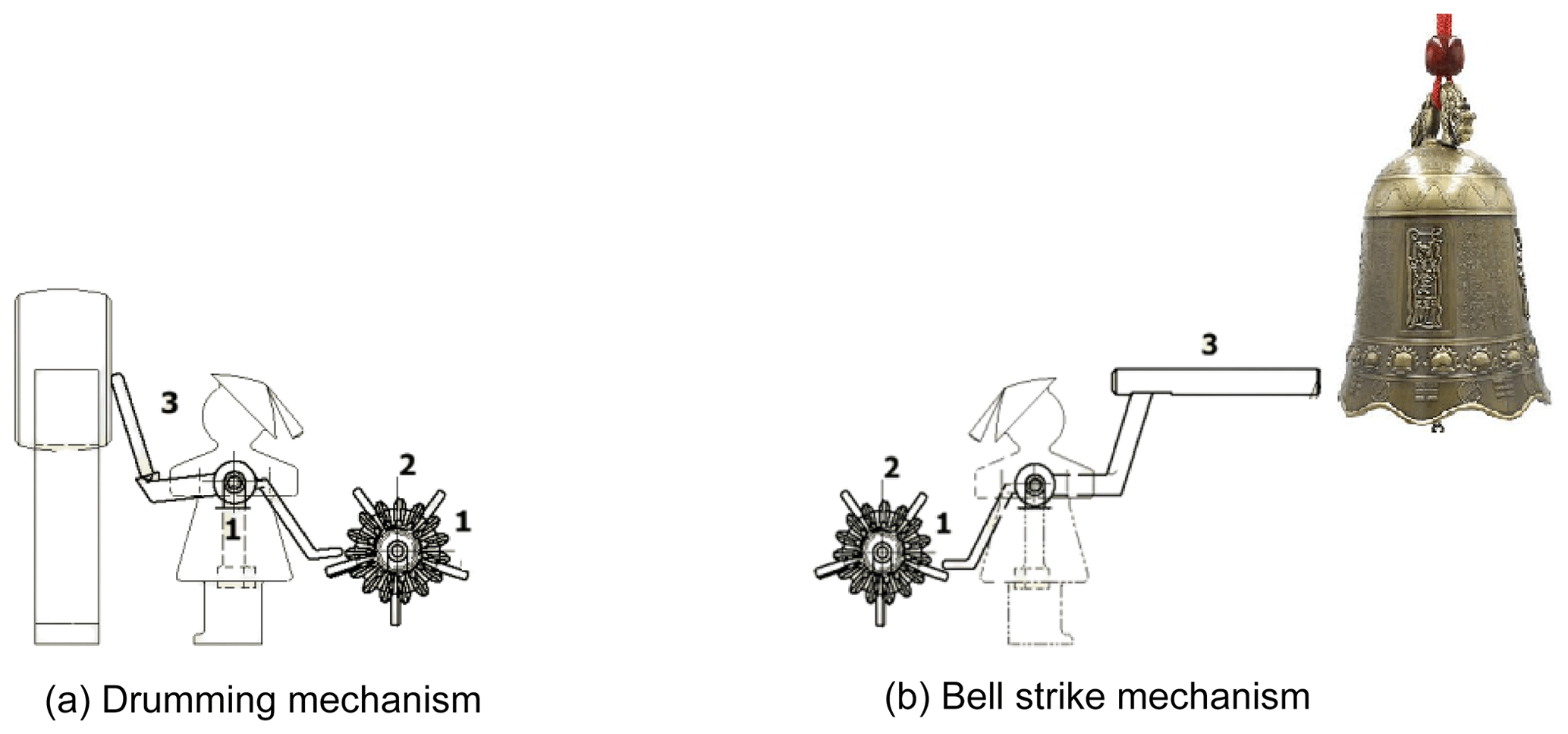
5.2.1 Reconstruction design for the time-reporting device
Based on the functional requirements of the time-reporting device, a corresponding and feasible specialized chain mechanism can be obtained, as shown in Fig. 21a–b.
5.3 Example 3: reconstruction design for the astronomical device
After obtaining the generalized chain atlas of the astronomical device, the following steps are used to obtain all possible specialization chains atlases:
-
For each generalized chain, identify the ground link.
-
For each case obtained in step 1, identify the active link.
-
For each case obtained in step 2, identify the intermediate shaft link.
-
For each case obtained in step 3, identify the idler link.
-
For each case obtained in step 4, identify the celestial globe link.
-
For each case obtained in step 5, identify the Sun link.
-
For each case obtained in step 6, identify the Moon link.
When performing the above steps, the following design requirements must be observed.
Ground link (link 1)
This is the frame and a multi-joint link.
Active link (link 2)
The active link receives periodic power input from the waterwheel. It is connected to the intermediate shaft link through the gear joint (G). It is a binary link.
Intermediate shaft link (link 3)
The intermediate shaft link is used to change the direction of movement. Based on the functional requirements of the astronomical device, it drives the Sun link and Moon link. In addition, it is connected to the adjacent links using gear joints (G). The intermediate shaft link is a multi-joint link.
Idler link (link 4)
The intermediate shaft link is used to change the direction of movement. Based on the functional requirements of the astronomical device, it changes the direction of rotation of the celestial globe link. Therefore, the idler link is connected to the adjacent links using a gear joint (G). This link is a ternary link.
The celestial globe link (link 5)
The celestial globe link is the driven link, which is connected to the Sun–Moon double link with a revolving joint (R). In addition, it is connected to the idler link with a gear joint (G) and to the ground link with a revolving joint (R). This link is a quaternary link.
Sun link (link 6)
The Sun link is a binary link and is connected to the celestial globe link through a revolving joint (R).
Moon link (link 7)
The Moon link is a binary link and is connected to the celestial globe link through a revolving joint (R).
In total, there are nine generalized chains atlas with seven members and 11 joints, as shown in Fig. 11.
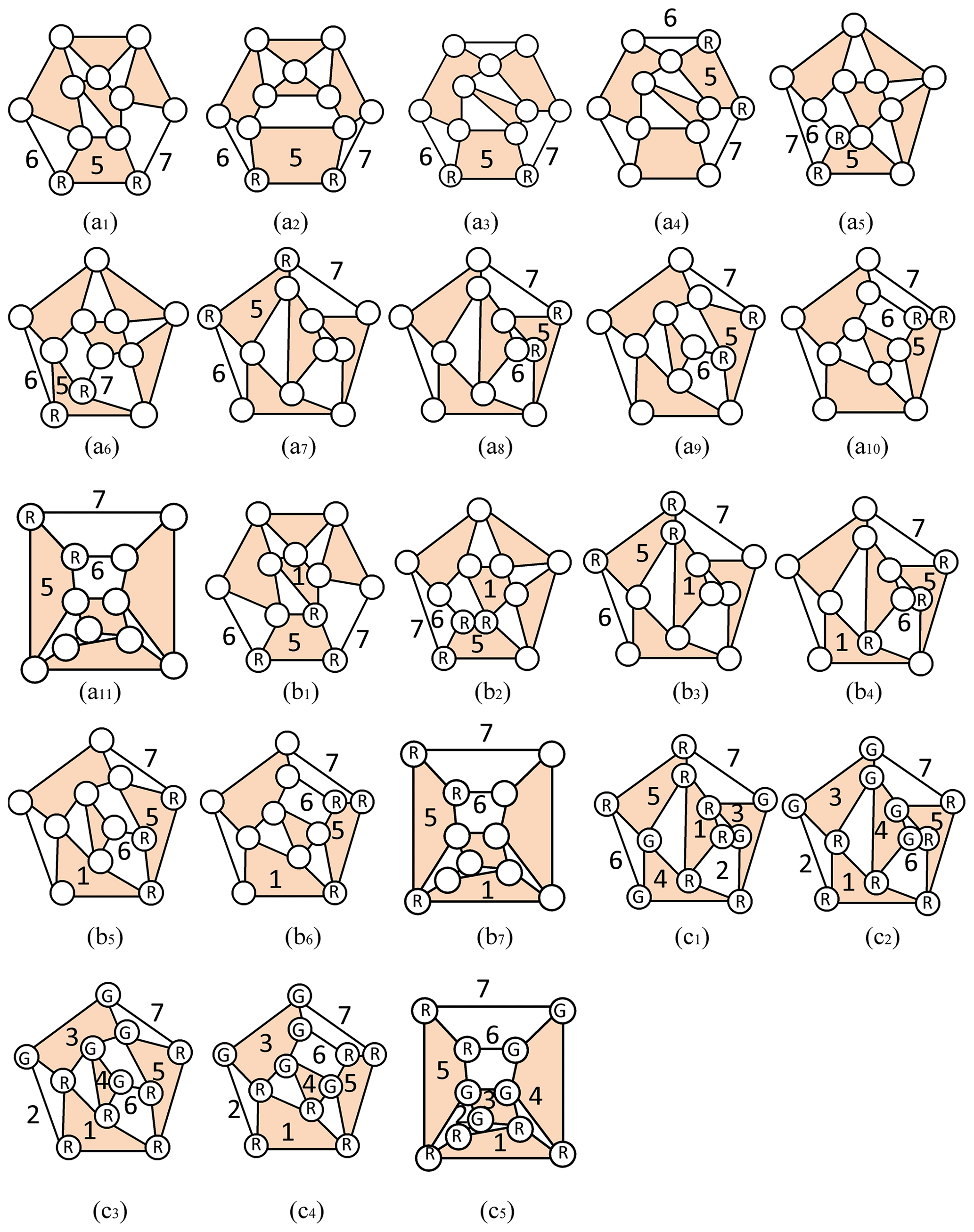
Celestial globe link (link 5), Sun link (link 6), and Moon link (link 7)
The celestial globe link is a quaternary link, and the Sun link and the Moon link are binary links. The celestial globe link is connected to the Sun link and the Moon link with a revolving joint (R). The celestial globe link 5, Sun link 6, and Moon link 7 are identified as follows:
-
For the generalized chain shown in Fig. 11a1, assigning celestial globe link 5, Sun link 6, and Moon link 7 generated one result (Fig. 22a1).
-
For the generalized chain shown in Fig. 11a2, assigning celestial globe link 5, Sun link 6, and Moon link 7 generated one result (Fig. 22a2).
-
For the generalized chain shown in Fig. 11a3, assigning celestial globe link 5, Sun link 6, and Moon link 7 generated two results (Fig. 22a3–a4).
-
For the generalized chain shown in Fig. 11a4, assigning celestial globe link 5, Sun link 6, and Moon link 7 generated one result (Fig. 22a5).
-
For the generalized chain shown in Fig. 11a5, assigning celestial globe link 5, Sun link 6, and Moon link 7 generated one result (Fig. 22a6).
-
For the generalized chain shown in Fig. 22a6, assigning celestial globe link 5, Sun link 6, and Moon link 7 generated two results (Fig. 22a7–a8).
-
For the generalized chain shown in Fig. 11a7, assigning celestial globe link 5, Sun link 6, and Moon link 7 generated one result (Fig. 22a9).
-
For the generalized chain shown in Fig. 11a8, assigning celestial globe link 5, Sun link 6, and Moon link 7 generated one result (Fig. 22a10).
-
For the generalized chain shown in Fig. 11a9, assigning celestial globe link 5, Sun link 6, and Moon link 7 generated one result (Fig. 22a11).
Therefore, assigning celestial globe link 5, Sun link 6, and Moon link 7 resulted in 11 specialized chains, as shown in Fig. 22a1–a11.
Ground link (link 1)
The ground link is a multi-joint link, and it cannot be connected to the Sun link and Moon link. The celestial globe link is connected through a revolving joint (R). In Fig. 22a1–a11, assigning ground link 1 resulted in seven possible solutions, as shown Fig. 22b1–b7.
Active link (link 2), intermediate shaft link (link 3), and idler link (link 4)
Based on the design requirements of the transmission mechanism, the active link, the intermediate shaft link, and the idler link are connected to each other through a gear joint (G). The intermediate shaft and idler link are connected to the Sun link and Moon link through a gear joint (G). In addition, the idler link is connected to the celestial globe link through a gear joint (G). For the conditions shown in Fig. 22b1–b7, and after assigning active link 2, intermediate shaft link 3, and idler link 4, there are five possible solutions, as shown in Fig. 22c1–c5.
5.3.1 Reconstruction design for example 3
Based on the functional requirements of the astronomical device and keeping the chain link and joint type unchanged, the direction of the motion of the Sun–Moon ring is opposite to that of the celestial globe based on design specification 3. The atlas of feasible specialized chains corresponding to Fig. 22c4–c5 is shown in Fig. 23.
5.4 3D virtual model and physical production
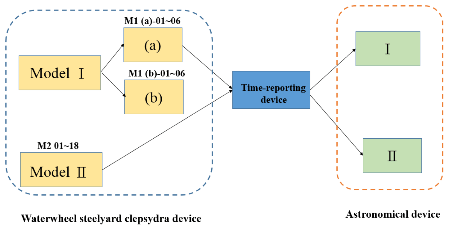
With the available models, this study designed 25 waterwheel steelyard clepsydras, one time-reporting device, and two astronomical devices. The possible configurations of the three devices are shown in Fig. 24.
In Fig. 24, there are three types of waterwheel steelyard clepsydra amounting to 25 sets, including one set of the time-reporting devices and one sets of astronomical devices. These can be combined into 50 sets of reconstructed designs. From these 50 possible designs, this study used the I-M1 (a)-03 model to construct the physical model shown in Fig. 25.

The water-powered celestial globe in ancient China was not only the first astronomical clock with a waterwheel steelyard clepsydra but also an astronomical clock with a time-reporting device. The invention of the waterwheel steelyard clepsydra also paved the way for ancient Chinese research on the periodic control of waterwheels. This led to the creation of Su Song's hydromechanical clock, which became the most well-known astronomical clock before the 14th century. Since historical records of the water-powered celestial globe are too simple and short, a full understanding of these ancient devices is not possible. It is, therefore, necessary to summarize its design specifications from historical records, which could then serve as the basis of the reconstruction design.
Through the reconstruction methods established in this study take into account the prevailing scientific theories and technical levels in ancient China, a total of 50 models were reconstructed. Because of limited historical records, the reconstructed designs contain multiple possible configurations. As more relevant historical materials and documents are unearthed in the future, the number of possibilities will decrease, and the restoration will become closer to reality. In other words, the set of systematic reconstruction design procedures presented in this study is one that is logical, and the solution obtained using this procedure should be very close to the actual water-powered celestial globe.
During the Northern Song Dynasty, Su Song's New Design for an Armillary Sphere and Celestial Globe described Zhang Sixun's Taiping armillary sphere as one driven by a waterwheel; it therefore should have a waterwheel steelyard clepsydra. It is hoped that the set of reconstruction design procedures presented in this study could be used as reference for the reconstruction of the waterwheel steelyard clepsydra used in the Taiping armillary sphere. With this in mind, the authors hope that the current study could point toward a research direction for interested scholars in the future.
The data are available upon request from the corresponding author.
ZHH is the lead author of this article. He was responsible for collecting the research literature, organizing the paper structure, and writing the paper. HSY and TYL provided the research direction of this paper, together with suggestions for the revision and correction of the paper.
The authors declare that they have no conflict of interest.
Publisher's note: Copernicus Publications remains neutral with regard to jurisdictional claims in published maps and institutional affiliations.
The authors are grateful to the Ministry of Science and Technology (Taiwan, ROC; grant no. MOST 106-2221-E-006-100-MY3) for the financial support for this work.
This research has been supported by the Ministry of Science and Technology, Taiwan (grant no. MOST 106-2221-E-006-100-MY3).
This paper was edited by Dario Richiedei and reviewed by Marco Ceccarelli and one anonymous referee.
Cao, M.: Zhong Hua Tien Wen Xue Shi, The Commercial Press, Taipei, Taiwan, 1986 (in Chinese).
Chen, L.: An investigation of the toothed wheel of Han Dynasty, Journal of Lanzhou University (social science), 32, 55–59, 2004 (in Chinese).
Hsiao, K.-H. and Yan, H.-S.: Mechanisms in Ancient Chinese Books with Illustrations, Springer, Switzerland, 2014.
Hu, W.-J.: Hsing yi hsiang fa yao: A Modern Interpretation, Liaoning Jiaoyu Publishing, Liaoning, China, 1997 (in Chinese).
Lee, Z.-C.: The history of water clock in ancient China, Anhui Science & Technology Publishing House, Anhui, China, 2015.
Lin, T.-Y.: A Systematic Reconstruction Design of Ancient Chinese escapement regulator, PhD Dissertation, National Cheng Kung University, Tainan, Taiwan, 2001 (in Chinese).
Liu, H.-C. and Wang, H. -Y.: On the skillful utilization of gear trains in ancient China, Journal of Tsinghua University, 6, 1–11, 1959 (in Chinese).
Liu, X., Zhang, Z., and Jia, W. (Later Jin Dynasty): Jiu Tang Shu, Ding Wen Publishing House, Taipei, Taiwan, 1981 (in Chinese).
Lu, J.-Y. and Hua, J.-M.: Zhon Gguo Ke Xue Jishu Shi Jixie juan, Science and Technology Press, Beijing, China, 2000 (in Chinese).
Nie, X.-Y.: Research on the bronze ratchet components unearthed from the Site of the Eastern Zhou Dynasty, Journal of Huanghe S & T University, 14, 34–35, https://doi.org/10.19576/j.issn.1008-5424.2012.04.010, 2012.
Pan, N.: The History of Ancient Chinese Astronomical Instruments, Shanxi Education Press, Taipei, Taiwan, 2005 (in Chinese).
Tuo, T. and A, L.-T. (Yuan Dynasty): Song Shi, Ding Wen Publishing House, Taipei, Taiwan, 1983 (in Chinese).
Xu, S. (Eastern Dynasty): Shuo Wen Jie Zi, Zhong Hua Book Company, Beijing, China, 1963 (in Chinese).
Yan, H.-S.: Creative Design of Mechanical Devices, Springer-Verlag, Singapore, 1998.
Yan, H.-S.: Reconstruction Designs of Lost Ancient Chinese Machinery, Springer Science & Business Media, Dordrecht, 2007.
Yan, H.-S.: Mechanisms: Theory and Applications, McGraw-Hill, Singapore, 2016.
- Abstract
- Introduction
- Historical archive and design specifications
- Characteristic of the interior mechanisms
- Process of reconstruction design
- Design examples
- Conclusion
- Data availability
- Author contributions
- Competing interests
- Disclaimer
- Acknowledgements
- Financial support
- Review statement
- References