the Creative Commons Attribution 4.0 License.
the Creative Commons Attribution 4.0 License.
 | 20 Sep 2021
Structure optimization design of a thin-film diffraction imaging system based on the Kriging model and the improved particle swarm optimization algorithm
Yitian Wang
Liu Zhang
Huanyu Zhao
Fan Zhang
A thin-film diffraction imaging system is a type of space telescope imaging system with high resolution and loose surface tolerance often used in various fields, such as ground observation and military reconnaissance. However, because this system is a large and flexible multi-body structure, it can produce flexural vibration easily during the orbit operation, which has a serious effect on the attitude stability of the system and results in low pointing accuracy. Therefore, this study proposes an optimization method based on the Kriging model and the improved particle swarm optimization algorithm to improve the stability and optimize the structure of the entire system. Results showed the area–mass ratio of the thin-film diffraction imaging system decreased by 9.874 %, the first-order natural frequency increased by 23.789 %, and the attitude stability of the thin-film diffraction imaging system improved.
- Article
(5435 KB) - Full-text XML
- BibTeX
- EndNote


A thin-film diffraction imaging system is a type of space telescope imaging system that uses a diffractive lens as the main mirror. Compared with traditional reflective telescopes, this system has high resolution and loose surface tolerance, which can improve the anti-interference ability of the optical system, and is used widely in various fields, including ground observation and military reconnaissance (Liu et al., 2018; He et al., 2020; Zhu et al., 2019). However, because this system is a large and flexible multi-body structure with a low natural frequency, the interference torque from inside and outside the satellite will induce an on-orbit vibration that has a serious effect on the attitude stability (Chen et al., 2021a, b). Therefore, establishing an accurate and effective structure optimization design for the thin-film diffraction imaging system is necessary to improve the natural frequency and enhance the attitude stability of the system (Tan et al., 2020).
Several works involving the optical structure of a thin-film diffraction imaging system have been conducted. In 2010, the Defense Advanced Research Projects Agency launched the Membrane Optical Imager for Real-Time Exploitation program and developed key technologies, such as diffractive films, onboard processing, and compression (Atcheson et al., 2014; Domber et al., 2014; Lee et al., 2016). In the same year, Deba et al. (2011) of the France National Space Research Center proposed a space diffraction telescope structure based on the Fresnel diffraction array. To study the mechanical structure of space cameras, Wei et al. (2017) used a weighted optimization method to optimize the truss support structure of space cameras, which improved the static and dynamic performances because the supporting structure between the main optical elements must maintain good rigidity and stability to ensure the positional relationship among the optical elements and accuracy of the ground observation. Han et al. (2019) proposed a scissors double-ring truss deployable mechanism to improve the rigidity of the antenna structure. However, the existing space support structure optimization method cannot determine how to build a complex functional model between the structural parameters and the natural frequency (Yuan and Yang, 2019; Yuan and Zhu, 2021).
At present, the mostly commonly used methods in the construction of approximate function models include response surface, neural network, and radial basis function models (Keshtegar et al., 2018; Kim et al., 2018; An et al., 2019). Compared with these methods, the Kriging model has global and local statistical characteristics and the ability to analyze the trends and dynamics of known information (Zhang et al., 2013b). Ye et al. (2018) used the Kriging model to correct the error between the measured and calculated values and combined it with the improved particle swarm optimization algorithm for application to the optimal design of electromagnetic devices. Bu et al. (2018) completed the multi-objective optimization design of a flywheel motor by considering the Kriging-model-based rotational inertia. Particle swarm optimization, the genetic algorithm, and the simulated annealing algorithm are often used to solve the global optimization problem of nonlinear multi-objective complex engineering systems. Chan et al. (2018) used the genetic algorithm to optimize the shape of Savonius turbine blades to improve the performance of Savonius wind turbines. Rehman et al. (2019) proposed the improved quantum-inspired particle swarm optimization algorithm that enhances the global search capability by adding enhancement factors to avoid premature convergence and improve the optimization efficiency of the algorithm. Wang et al. (2011) optimized the structural parameters of rollover protective structures (ROPS) by combining the Kriging model and the genetic algorithm, which effectively improved the energy absorption capacity of ROPS. Zhang et al. (2013a) used a design method based on the Kriging model and the genetic algorithm for parameter optimization to optimize the parameters of large-scale ball mill gears, which improved the reliability of the structure. Lv et al. (2018) proposed the improved particle swarm optimization algorithm based on the last-eliminated principle and an enhanced local–global information sharing capability to solve engineering optimization problems. Compared with the traditional particle swarm optimization algorithm, this algorithm has the advantages of not easily falling into local optimum and overcoming premature convergence, which effectively reduces the number of iterations and greatly improves the computational efficiency.
This study proposes a method based on the Kriging model and the improved particle swarm optimization algorithm to optimize the structure of thin-film diffraction imaging systems. A thin-film diffraction imaging system has multiple structural parameter variables. Thus, the quality and stability of the system structure are greatly affected, even by a very slight change in the structural parameters of the system. Aiming at the structural particularity of the thin-film diffraction imaging system, Kriging and the improved particle swarm optimization method can accurately establish the mathematical model between structural parameters and system frequency, with the advantage of high convergence accuracy. The remainder of this paper is organized as follows. A design of the initial topology of the thin-film diffraction imaging system is presented in Sect. 2. The improved particle swarm optimization algorithm and an optimization scheme based on Kriging and multi-objective particle swarm optimization are proposed in Sect. 3. And then a series of optimized structural parameters are obtained from the application of the improved particle swarm optimization algorithm, and the corresponding discussion is presented in Sect. 4. In Sect. 5, conclusions are drawn.
The thin-film diffraction imaging system is a large-aperture space telescope imaging system that executes transmission imaging as an imaging method. The main mirror material is a thin-film material with a thickness of only tens of microns. The block form of the main mirror should be simplified to control the mirror distortion and improve the reliability of the system and obtain a symmetric main mirror to maintain stability. The structure design diagram of the thin-film diffraction imaging system is shown in Fig. 1. The structure adopts a rotary hinge to connect the two sub-mirror support frames of the system.
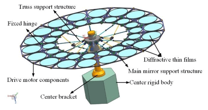
This study considers two parts that have considerable effects on the structural rigidity and stability of the system: the main mirror and the truss support structure. Since the optical design index of the thin-film diffraction imaging system determines its structural design size requirements, the system adopts a double-layer ring design, which can effectively increase the film area and improve the imaging quality of the thin-film diffraction imaging system.
The main mirror support structure of the film diffraction imaging system is composed of the diffraction film and the main mirror (Fig. 2).
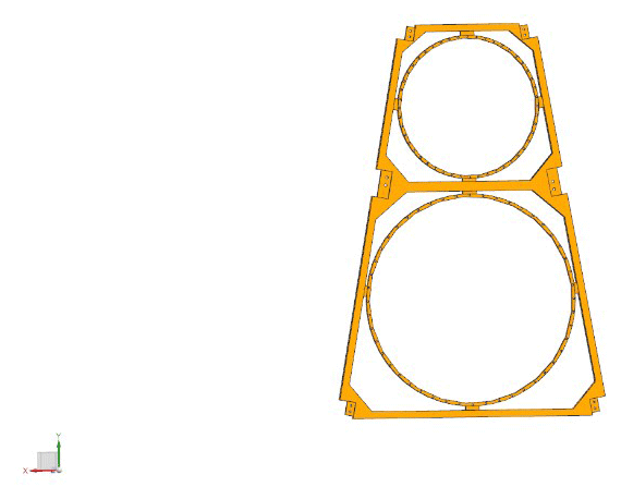
Figure 2Schematic of the main mirror support structure of the thin-film diffraction imaging system.
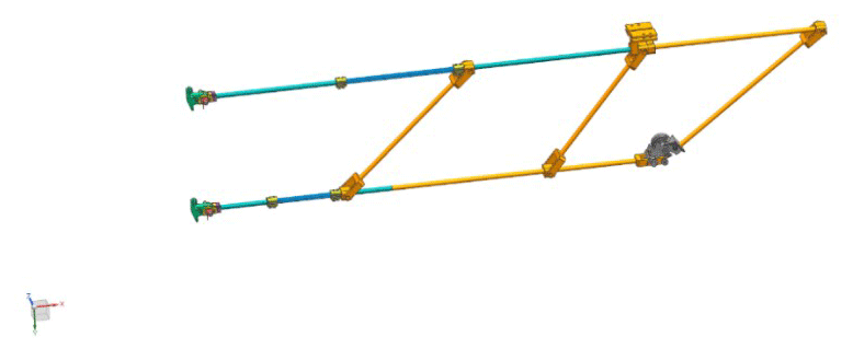
The truss support structure of the thin-film diffraction imaging system is shown in Fig. 3. The principle of this structure is to convert the bending load of the component into tension and compression loads. This method effectively utilizes the tension- and compression-bearing capacities of the material, which are greater than the bending bearing capacity, improves the rigidity of the imaging system, and adopts the flexible assembly method to reduce manufacturing and processing difficulties. Efficient trusses should have the following basic characteristics. First, the inclined rods should be arranged as far as possible on the 45∘ diagonal. If the truss structure prohibits the inclined rods to be arranged at this angle, they should be separated as close as possible to an angle of approximately 45∘. The structural efficiency will decline substantially if the members are arranged with a small diagonal angle. Second, three supporting hinges should be set on the truss support structure to maintain its folding and unfolding functions. Lastly, because of the anisotropic characteristics of the carbon fiber composite material, a space camera support structure with excellent mechanical and thermal properties should be used in a reasonable layer design.
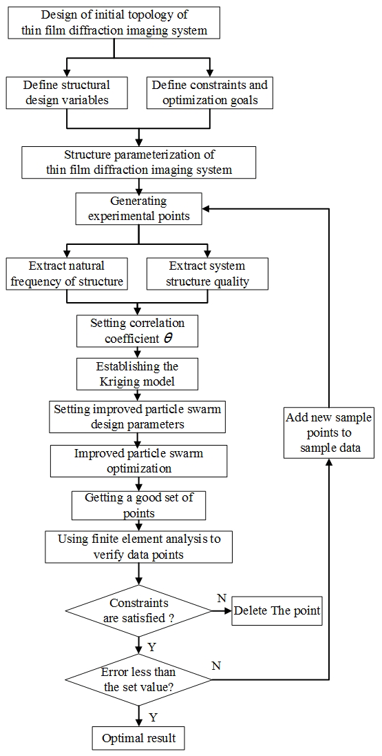
3.1 Optimization method flow
The Kriging model and the improved particle swarm optimization algorithm are the main optimization methods used in this study. The optimization process is illustrated in Fig. 4 (Zhang et al., 2013b).
-
Determine the initial topology of the thin-film diffraction imaging system and the system structure design variables, constraints, and optimization objective function, and then parameterize the structural model of the system.
-
Perform modal analysis on the thin-film diffraction imaging system to analyze the mass and frequency characteristics of the initial structure.
-
Determine the upper and lower limits of the design variables according to the size constraints. Subsequently, determine the initial sample points using the Latin hypercube sampling method, substitute each group of sample points into the finite element software as the size parameters for the modal analysis, and record the first four natural frequencies after removing the rigid body mode (Chen et al., 2018, 2020). Finally, calculate the mass of the system.
-
Determine the correlation parameters of the Kriging model, construct the Kriging proxy model according to the response value, and use the improved particle swarm optimization algorithm to determine the optimal design point.
-
Determine the optimized results, and verify the constraints and convergence conditions. Delete the result if the constraints and convergence conditions are not satisfied. If the result satisfies the constraint conditions but not the convergence ones, return to step (3), add the obtained points to the initial set of sample points to update the Kriging model, and apply it to the next optimization. If the result satisfies both conditions, the result is regarded as the best result.
3.2 Kriging model
The Latin hypercube sampling method is adopted to satisfy the principles of uniformity and orthogonality (Liu et al., 2019). As a semi-parametric interpolation method, the Kriging model includes polynomial and random parts (Li et al., 2019; Gong et al., 2019; Xiao et al., 2020), which can be expressed as
where y(x) is the function estimate of the unknown point, f(x) represents the deterministic function, which is assumed to be constant because the random part possesses sufficient ability to capture the change trend of the objective function, β is the corresponding regression coefficient of the error of the random distribution, z(x) provides the approximate value of the local error, and z(x) has the following statistical characteristics:
where xi and xj are two arbitrarily selected interpolation points in the sample space, θ is the model correlation parameter, and is the spatial correlation function between the xi and xj of the two sample points with parameter θ, which is used to represent the spatial correlation among the training sample points. The Gaussian correlation function is adopted, which is expressed as
where and represent the mth element of vector xi and xj, and θm is the unknown related parameter that must be determined. The linear combination of the known sample point's response values can be used to estimate the response values of any given sample point. After the derivation, the predicted value of the model is given as
where is the response value, is the estimated value when f(x) is constant, f is the post vector, and rT(x) is the correlation vector with length s between the untested point x and the sampling data point :
where is an estimate that can be calculated as
The variance can be determined through and y as
where θk is the unbiased estimator of the Kriging model, which can be calculated as
The optimal value of θk can be calculated using the optimization method, and the value of this function is maximized; the Kriging proxy model constructed through this method obtains the highest accuracy. Therefore, the problem of constructing the optimal Kriging model is transformed into a nonlinear unconstrained optimization problem. The improved particle swarm optimization algorithm will then be used to solve the maximization problem of Eq. (10) to obtain the optimal value of θk.
3.3 Improved particle swarm optimization algorithm
Particle swarm optimization is an evolutionary calculation method based on swarm intelligence. The system initializes a group of particles randomly through the system and searches for the optimal solution continuously and iteratively (Wang et al., 2018). The iteration formula is as follows:
where i=1, 2, 3, …, n, d=1, 2, 3, …, D, k represents the number of the current iterations of the particle, represents the d-dimensional speed of the ith particle in the kth iteration, represents the coordinates of the individual extreme value of the ith particle in the dth dimension in the kth iteration, represents the position component of the ith particle in the dth dimension in the kth iteration, is the dth dimension component of the particle's optimal solution vector in the kth iteration, ω is the inertia weight of the velocity, c1 and c2 are the learning factors, and r1 and r2 are random real numbers between (0,1). The particle swarm optimization algorithm has convenient calculation and fast solution speed. However, due to the loss of diversity of the population particles in the operation process, this algorithm easily falls into the local optimal solution under fixed weight and results in prematurity.
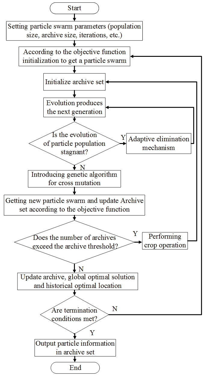
The genetic algorithm is introduced to avoid the abovementioned problem and update the archive set through cross mutation to maintain the diversity of the population. The improved particle swarm optimization algorithm then obtains improved global search characteristics (Zhang et al., 2013b). The flow chart of the process is shown in Fig. 5.
4.1 Initial structural analysis
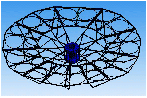
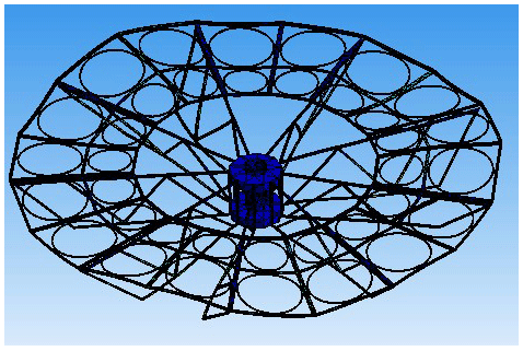
For a certain type of thin-film diffraction imaging system (hereinafter referred to as “system”), the center rigid body and the center bracket assembly only provide gravity load, which does not affect the finite element analysis of the overall structure. As a flexible accessory, diffractive film has little effect on the vibration of the system. To improve the calculation efficiency, the center rigid body and the center support assembly are simplified as mass points, and the diffraction film is removed, which will not affect the overall finite element analysis. The hexahedral mesh is mainly used in the system model; the simplified structure after the finite element mesh is divided by the finite element software is illustrated in Fig. 6. After grid division, the thin-film diffraction imaging system model contains a total of 17 866 units and a total of 45 351 nodes.
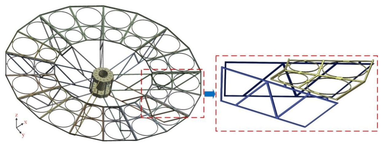
Figure 6Schematic of the equivalent structure of thin-film diffraction imaging system after gridding.
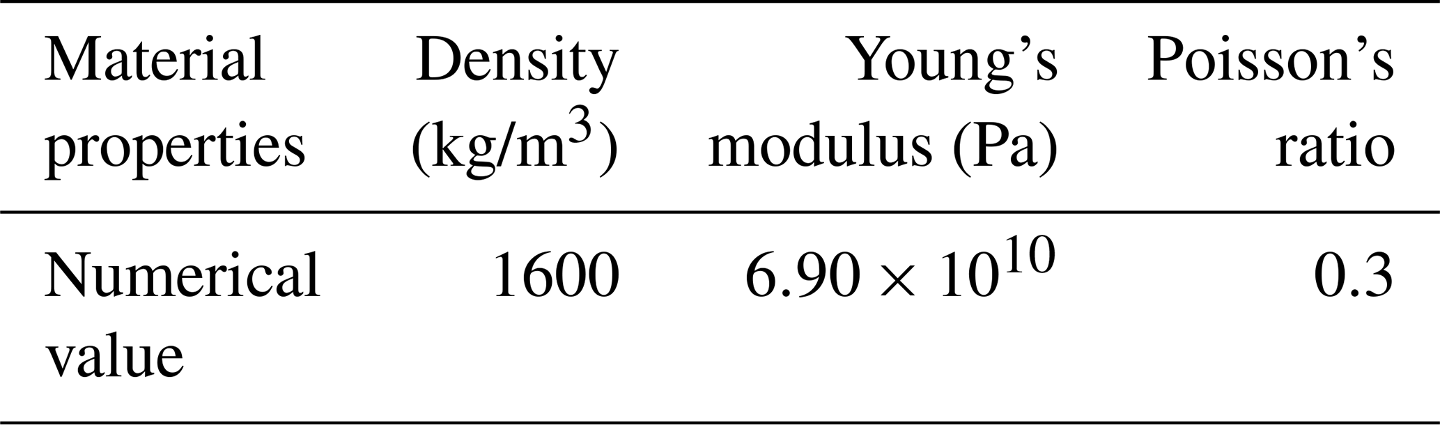
The engineering requirements indicate that the area–mass ratio of the thin-film diffraction imaging system should be less than 2, and the first-order natural frequency should be greater than 26 Hz. The carbon fiber composite is used as the support structure material to reduce the mass of the system and improve the structural rigidity. Compared with traditional metal materials, carbon fiber materials have advantageous physical and mechanical properties, such as small density, high specific strength, high specific rigidity, and good thermal stability (Table 1).
The initial structure parameters of the thin-film diffraction imaging system are selected from the above properties and are summarized in Table 2.
Table 2Initial structure parameters of the thin-film diffraction imaging system.

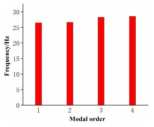
The main mirror assembly of the optical imaging system will exhibit strong vibrations as a large flexible accessory when the film diffraction imaging system is in orbit. To analyze the vibration characteristics, identify the modal parameters of the system, and provide a basis for structural optimization, the free mode analysis of the film diffraction imaging system under the unconstrained condition is performed. The overall vibration of the system can be expressed as the linear combination of modes with various orders. Theoretically, the number of modes is infinite. Given that the vibration characteristics of the structure are generally determined by the low-order vibration characteristics, the first fourth-order mode shape after the removal of the first sixth-order rigid body mode by the thin-film diffraction imaging system is selected for the modal analysis. The change trend of the free mode frequency is shown in Fig. 7.
Figures 8–11 show the first fourth-order mode shapes of the equivalent structure of the thin-film diffraction imaging system after removing the first sixth-order rigid body mode under free modal analysis. Table 3 presents the values of the first four natural frequencies and the mode characteristics of each stage of the thin-film diffraction imaging system.
Table 3Natural frequencies of the first- to fourth-order free modes of the thin-film diffraction imaging system.
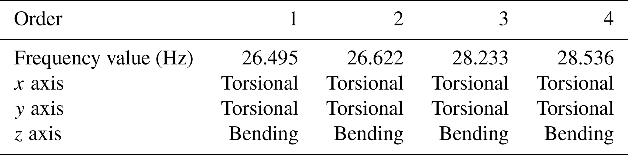

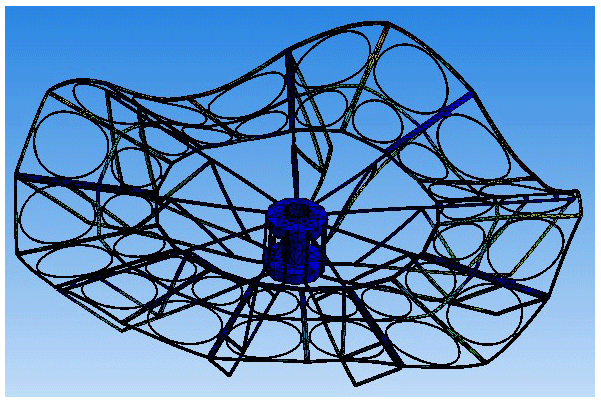
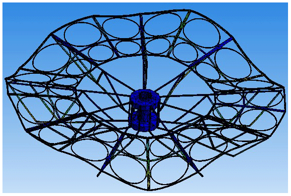
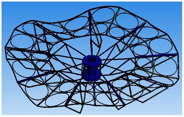
The natural frequencies of the free mode of the thin-film diffraction imaging system and the corresponding mode shapes are determined to check the rationality of the structural design. The natural frequencies of the first six modes of the system are all 0, indicating that the system does not have elastic vibration characteristics when performing a rigid body motion. Hence, the influence of the first six modes on the structure will not be analyzed. Table 3 shows that the natural frequency distribution of the first to fourth orders after removing the first sixth-order rigid body mode of the system ranges between 26.495 and 28.536 Hz. As shown in Figs. 8–11, the first-order frequency is 26.495 Hz, which is generally manifested as the torsional vibration of the entire structure along the x axis and the bending vibration around the z axis; the vibration of the main mirror supporting structure is intense in this case. The second-order frequency is 26.622 Hz, which is generally manifested as the square of the entire structure along the x axis and the torsional and bending vibrations around the z axis; the vibration of the truss support structure is intense in this case. The third-order frequency is 28.233 Hz, and the overall performance involves the torsional vibration of the entire structure along the x axis and the bending vibration around the z axis; the vibration of the truss support structure is intense. The fourth-order frequency is 28.536 Hz, whereby the overall performance is the torsional vibration of the entire structure along the x axis and the bending vibration around the z axis; the main mirror support structure vibrates violently.
This study optimizes the structure of the main mirror support structure and the truss support structure to effectively restrain the flexible vibration of the supporting structure and improve the rigidity and attitude stability of the thin-film diffraction imaging system.
After the calculation, the mass of the initial system structure is 108.36 kg, whereby 15.66 kg is the mass of the supporting structure mass and the area–mass ratio of the system is 2.21. Therefore, reducing the mass of the system and improving the natural frequencies while maintaining the area–mass ratio is necessary.
4.2 Optimization parameter design
4.2.1 Design variable
Given that the supporting structure of the system is composed of multiple longitudinal beams, the length, width, and thickness of such beams directly affect the mass and rigidity of the supporting structure. Therefore, the proposed optimization design problem includes 13 design variables, such as the height of the main mirror support structure flange; the length, width, and thickness of the support beam; and the position parameters of the support hinges. The design area size is 1300 mm × 320 mm. One end of the center rigid body is fixed, and the internal structure has a staggered reinforcement. The design variables of the truss support structure are presented in Fig. 12.
To reduce the bending vibration of the main mirror support structure in the z axis and enhance the stability of the structure, the main mirror support structure adopts the structural form of a U-shaped beam, and the flange heights are selected as the design variables (Fig. 13).
The selected independent design variables include
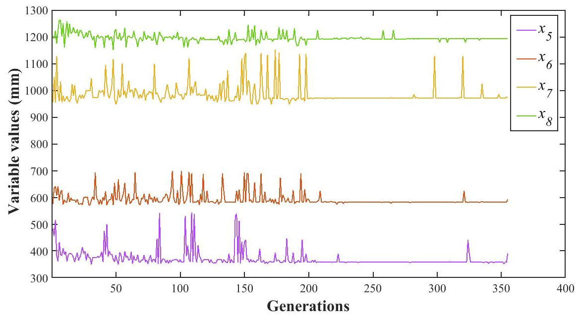
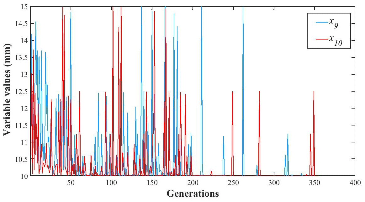
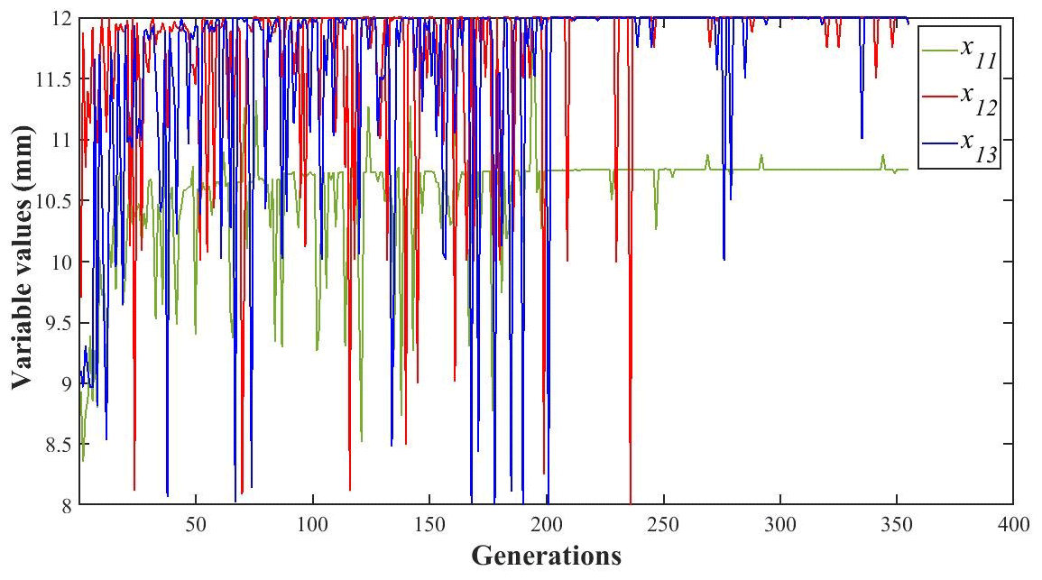
where x1, x2, x3, and x4 are the widths of rods 1, 2, 3, and 4, respectively; x5 is the distance between rod 1 and the center rigid body in the x axis; x6 is the distance between support hinge 1 and the center rigid body in the x axis; x7 is the distance between supporting hinge 2 and the center rigid body in the x axis; x8 is the distance between supporting hinge 3 and the center rigid body in the x axis; x9 is the width of rod 1; x10 is the width of rod 2; x11 is the thickness of the entire truss structure; x12 is the height of the outer flange of the main mirror support structure; and x13 is the height of the inner flange of the main mirror support structure.
4.2.2 Objective function
In the structural design and simulation stage, the natural frequencies of the supporting structure should be increased to ensure that the supporting structure has high rigidity and stability and to avoid the influence of the satellite platform vibration on the accuracy of the optical components. On this basis, this study increases the natural frequencies of the thin-film diffraction imaging system while minimizing the structural mass. The objective function is expressed as
where f1, f2, f3, and f4 are the first-, second-, third-, and fourth-order natural frequencies after removing the first sixth-order rigid body modes of the thin-film diffraction imaging system, respectively; α1, α2, α3, and α4 are the respective weight factors of each natural frequency; ; and m is the total mass of the thin-film diffraction imaging system.
4.2.3 Constraint conditions
Boundary constraints of the design variables
The constraints of the design variables according to the design space constraints of the support structure of the thin-film diffraction imaging system are provided as follows:
Mass constraints
The mass constraints should be selected in consideration of the area–mass ratio required by the project. This ratio is the quotient of the total mass of the support structure of the thin-film diffraction imaging system and the maximum area of the main mirror. As previously mentioned, the required area–mass ratio in engineering is less than 2. For the selected material (i.e., carbon fiber material), the maximum diameter of the film diffraction imaging system is 3000 mm. After calculation, the total mass of the support structure of the film diffraction imaging system m1 should not exceed 14.13 kg, the total mass of the center rigid body and the center support assembly m2 should be 92.7 kg, and the total mass of the structure m shall not exceed 106.83 kg.
4.3 Kriging model
Establishing the Kriging model does not require excessively many sample points. Following the upper and lower limits of the design variables, 500 groups of initial sample points are selected using the Latin hypercube sampling method. If too many sample points are selected, the modeling efficiency will be reduced, and the accuracy of the modeling will be limited. Therefore, it is decided to select 500 sets of sample points after comprehensive consideration. The correlation coefficients of the Kriging model are listed in Table 4. After the Kriging model is established, 300 groups of sample points are selected and calculated. The maximum absolute error (MAAE), minimum absolute error (MIAE), average absolute error (MAE), average relative error (AEV), mean square error (MSE), root mean square error (RMSE), and square error of relative error (Rev) in the prediction results of the Kriging model are listed in Table 5. The results show that the absolute error value of the Kriging agent model is small, and the relative error value is less than 3 %, thereby satisfying the engineering accuracy requirements. This value signifies the ability of the model to accurately reflect the mapping relationship between the structural parameters of the thin-film diffraction imaging system and the natural frequency and structural mass. In conclusion, the Kriging proxy model can replace the finite element simulation model and optimize the structure of the thin-film diffraction imaging system to determine the optimal solution of the 13 design variables.
Table 5Accuracy verification results of the Kriging agent model.
4.4 Global optimization
Given that the low-order vibration characteristics of the thin-film diffraction imaging system exert a great influence on the system vibration characteristics, the high-order vibration characteristics slightly influence the vibration characteristics of the system. Thus, the low-order vibration characteristics play a decisive role in the dynamic characteristics of the structure. In the analysis of the dynamic characteristics of the thin-film diffraction imaging system, the first-order mode greatly influences the system vibration, and its influence is approximately twice that of the second-, third-, and fourth-order modes. Therefore, the weighting factors of the first four natural frequencies are α1=0.4, α2=0.2, α3=0.2, and α4=0.2. The parameters of the improved particle swarm algorithm and its maximum search speed are listed in Tables 6 and 7, respectively.
Table 6Parameters of the improved particle swarm algorithm optimization.

Table 7Maximum search speed of the improved particle swarm algorithm.

4.5 Optimization results
The changes in each design variable during the optimization process are illustrated in Figs. 14, 15, 16 and 17 and the change in the objective function value is shown in Fig. 18.


The changes in the structural mass of the thin-film diffraction imaging system and the first four natural frequencies are shown in Figs. 19 and 20, respectively.
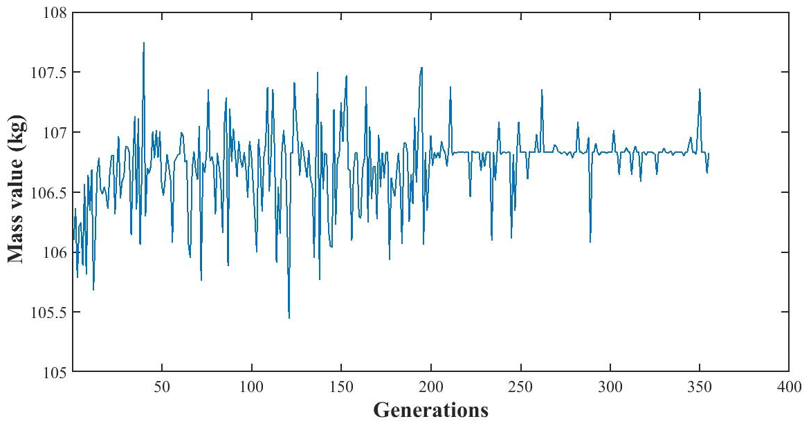
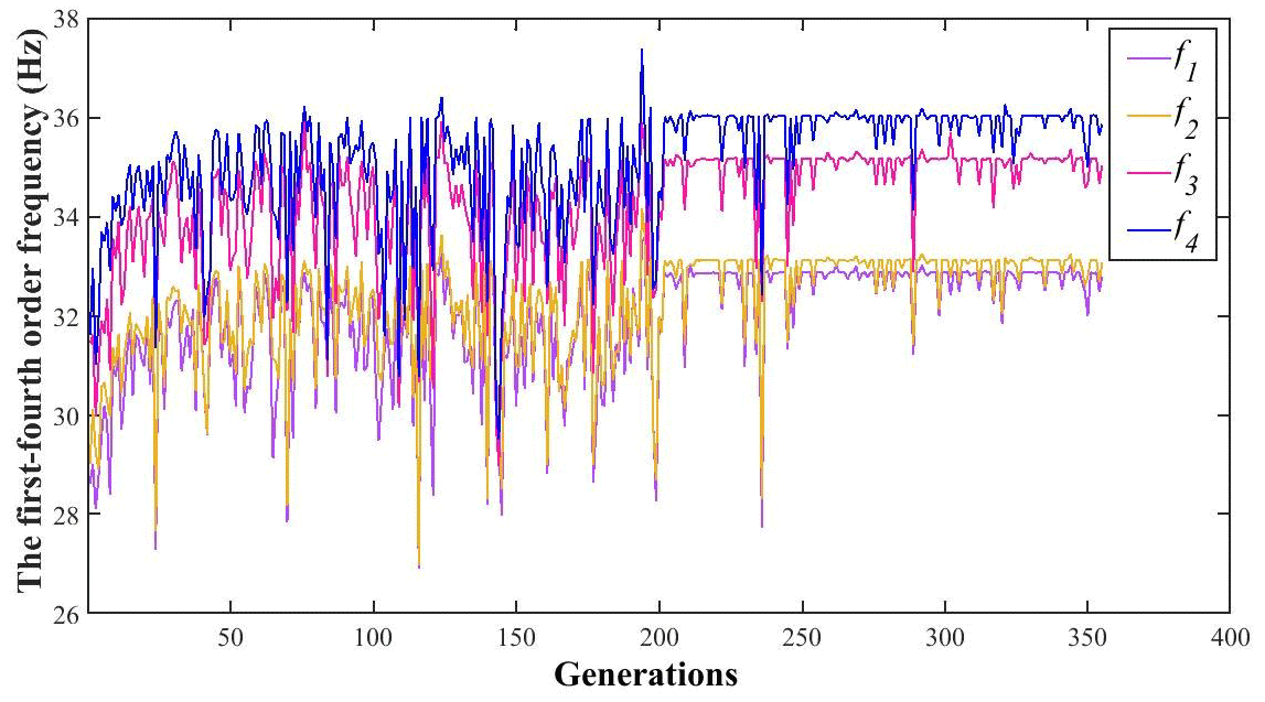
Figure 20Variations of the first- to fourth-order frequency changes under different numbers of generation.
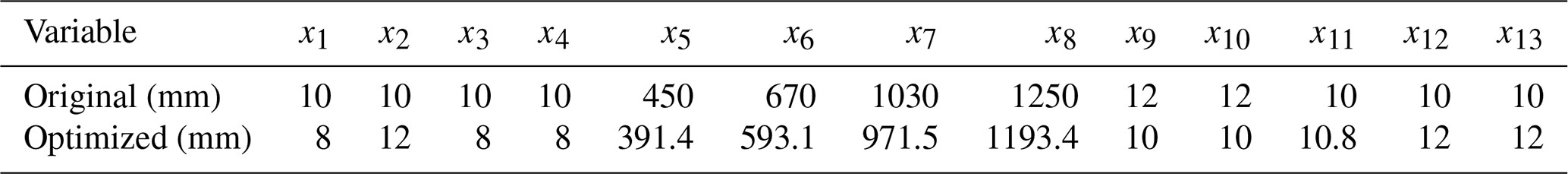
The improved particle swarm optimization algorithm based on the Kriging model is used to optimize the structure of the thin-film diffraction imaging system. The optimal results are obtained after 355 cycles. Given that the Kriging model represents an approximate real response surface, the points that meet the limit conditions during the optimization process may not fully meet the limit conditions in the real model (Fig. 4). The main results of the optimized particle swarm optimization algorithm are selected and inputted into the finite element analysis of the thin-film diffraction imaging system. Subsequently, the structural performance of the system is analyzed to determine whether the optimization results meet conditions. The initial values of the structural parameters and the final optimized design results after the optimization and rounding of values are summarized in Table 8.
Table 8Structural parameters of the thin-film diffraction imaging system.
The structural parameters obtained by the improved particle swarm optimization algorithm are used as the structural parameters of the thin-film diffraction imaging system, which are then substituted into the finite element software for the modal analysis. The modal shapes are shown in Figs. 21–24.
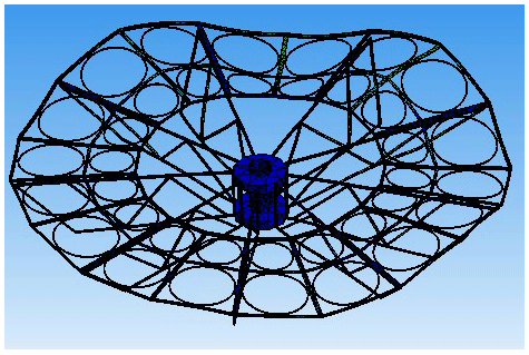
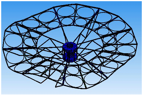
Figures 21–24 show the flexible vibration produced by the improved film diffraction imaging system in orbit is suppressed effectively and the overall vibration amplitude of the structure decreased. After the structural optimization, the mass of the supporting structure decreased from 15.669 kg to 14.127 kg, which is 9.841 % lower than before the optimization (Table 9). Similarly, the mass of the thin-film diffraction imaging system decreased from 108.369 to 106.827 kg, which is 1.423 % lower than that before optimization. The area–mass ratio decreased from 2.218 to 1.999 kg/m2, which satisfies the design requirements. In the free mode analysis after removing the first sixth-order rigid modes, the first-order mode frequency of the structure increased from 26.495 to 32.798 Hz (23.789 %), the second-order mode frequency increased from 26.622 to 33.076 Hz (24.243 %), the third-order mode frequency increased from 28.233 to 35.026 Hz (24.06 %), and the fourth-order mode frequency increased from 28.536 to 35.860 Hz (25.666 %).
Table 9Optimization results of the thin-film diffraction imaging system.

The findings suggest the mass of the support structure of the optimized thin-film diffraction imaging system decreased significantly while the corresponding rigidity and stability improved significantly; thus, the optimized design of the complex structure of the system is achieved.
In view of the complex structure optimization of thin-film diffraction imaging systems, the following conclusions are obtained:
-
The initial topology of the thin-film diffraction imaging system is selected, and a parametric finite element model of the system is established based on the Ansys Workbench, which is used to perform the modal analysis of the system. The Kriging model is used to replace the function model between the structural parameters and the natural frequencies to address the difficulty in accurately establishing the complex function relationship between both factors. The convergence accuracy of the Kriging model reached 10−3, which implies that the calculation efficiency greatly improved.
-
To solve the problem of the traditional particle swarm optimization algorithm easily falling into the local optimal solution under fixed weight, the improved particle swarm optimization algorithm is proposed and applied to the structural optimization design of the thin-film diffraction imaging system. The combination of the Kriging model and the improved particle swarm optimization algorithm can quickly converge to the global optimal solution and significantly improve the efficiency of optimization.
-
The theoretical assumption of this study is verified using a certain type of thin-film diffraction imaging system. A structural optimization method based on the Kriging model and the improved particle swarm optimization algorithm is utilized to improve the natural frequencies and effectively enhance the attitude stability of the film diffraction imaging system.
All the code and data used in this paper can be obtained upon request to the corresponding author.
YW presented the overall structure and optimization. HZ and FZ designed the major work components. LZ did the mechanical analysis.
The authors declare that they have no conflict of interest.
Publisher's note: Copernicus Publications remains neutral with regard to jurisdictional claims in published maps and institutional affiliations.
This work was funded by the National Natural Science Foundation of China (grant no. 62001185), the National Key Research and Development Program of China (grant nos. 2016YFB0501000 and 2016YFB0501003, and the Shanghai Aerospace Science and Technology Innovation Fund (grant no. 11602145).
This research has been supported by the National Outstanding Youth Science Fund Project of the National Natural Science Foundation of China (grant no. 62001185), the National Key Research and Development Program of China (grant nos. 2016YFB0501000 and 2016YFB0501003), and the Shanghai Academy of Spaceflight Technology (grant no. 11602145).
This paper was edited by Peng Yan and reviewed by three anonymous referees.
An, Y., Wang, X., Qu, Z., Liao, T., Wu, L., and Nan, Z.: Stable temperature calibration method of fiber Bragg grating based on radial basis function neural network, Opt. Eng., 58, 096105, https://doi.org/10.1117/1.oe.58.9.096105, 2019.
Atcheson, P., Domber, J., Whiteaker, K., Britten, J. A., Dixit, S. N., and Farmer, B.: MOIRE – Ground Demonstration of a Large Aperture Diffractive Transmissive Telescope, in: Space Telescopes and Instrumentation 2014: Optical, Infrared, and Millimeter Wave, edited by: Oschmann, J. M., Clampin, M., Fazio, G. G., and MacEwen, H. A., Proceedings of SPIE, Spie.-Int. Soc. Optical Engineering, Bellingham, 2014.
Bu, J. G., Lan, X. D., Zhou, M., and Lv, K. X.: Performance Optimization of Flywheel Motor by Using NSGA-2 and AKMMP, IEEE T. Magn., 54, 1–7, https://doi.org/10.1109/tmag.2017.2784401, 2018.
Chan, C. M., Bai, H. L., and He, D. Q.: Blade shape optimization of the Savonius wind turbine using a genetic algorithm, Appl. Energ., 213, 148–157, https://doi.org/10.1016/j.apenergy.2018.01.029, 2018.
Chen, Y., Joffre, D., and Avitabile, P.: Underwater Dynamic Response at Limited Points Expanded to Full-Field Strain Response, J. Vib. Acoust., 140, 051016, https://doi.org/10.1115/1.4039800, 2018.
Chen, Y., Avitabile, P., and Dodson, J.: Data Consistency Assessment Function (DCAF), Mech. Syst. Signal Pr., 141, 106688, https://doi.org/10.1016/j.ymssp.2020.106688, 2020.
Chen, Y., Avitabile, P., Page, C., and Dodson, J.: A polynomial based dynamic expansion and data consistency assessment and modification for cylindrical shell structures, Mech. Syst. Signal Pr., 154, 107574, https://doi.org/10.1016/j.ymssp.2020.107574, 2021a.
Chen, Y., Escalera Mendoza, A. S., and Griffith, D. T.: Experimental and numerical study of high-order complex curvature mode shape and mode coupling on a three-bladed wind turbine assembly, Mech. Syst. Signal Pr., 160, 107873, https://doi.org/10.1016/j.ymssp.2021.107873, 2021b.
Deba, P., Etcheto, P., and Duchon, P.: Preparing the way to space borne Fresnel imagers Space scenarios optical layouts, Exp. Astron., 30, 123–136, https://doi.org/10.1007/s10686-010-9202-5, 2011.
Domber, J. L., Atcheson, P. D., and Kommers, J.: MOIRE: Ground Test Bed Results for a Large Membrane Telescope, Spacecraft Structures Conference, Proceedings, 13–17 January 2014, National Harbor, Maryland, USA, AIAA SciTech Forum 2014, American Institute for Aeronautics and Astronautics Curran Associates, Inc., 2014.
Gong, J., Zhang, H., Zhao, B., Fu, D., and Gillon, F.: Proposal of a Bi-Objective Kriging Adapted Output Space Mapping Technique for Electromagnetic Design Optimization, IEEE T. Magn., 55, 1–5, https://doi.org/10.1109/tmag.2019.2907877, 2019.
Han, B., Xu, Y., Yao, J., Zheng, D., Li, Y., and Zhao, Y.: Design and analysis of a scissors double-ring truss deployable mechanism for space antennas, Aerosp. Sci. Technol., 93, 105357, https://doi.org/10.1016/j.ast.2019.105357, 2019.
He, C., Huang, P., Dong, X., and Fan, B.: Optical design of compact unobscured ground-based diffractive telescope, Optik, 205, 163696, https://doi.org/10.1016/j.ijleo.2019.163696, 2020.
Keshtegar, B., Hao, P., Wang, Y., and Hu, Q.: An adaptive response surface method and Gaussian global-best harmony search algorithm for optimization of aircraft stiffened panels, Appl. Soft Comput., 66, 196–207, https://doi.org/10.1016/j.asoc.2018.02.020, 2018.
Kim, H., Sui, C., Cai, K., Sen, B., and Fan, J.: An Efficient High-Speed Channel Modeling Method Based on Optimized Design-of-Experiment (DoE) for Artificial Neural Network Training, IEEE T. Electromagn. C., 60, 1648–1654, https://doi.org/10.1109/temc.2018.2796091, 2018.
Lee, N., Backes, P., Burdick, J., Pellegrino, S., Fuller, C., Hogstrom, K., Kennedy, B., Kim, J., Mukherjee, R., Seubert, C., and Wu, Y.-H.: Architecture for in-space robotic assembly of a modular space telescope, Journal of Astronomical Telescopes Instruments and Systems, 2, 041207, https://doi.org/10.1117/1.jatis.2.4.041207, 2016.
Li, N., Yang, L., Li, X., Li, X., Tu, J., and Cheung, S. C. P.: Multi-objective optimization for designing of high-speed train cabin ventilation system using particle swarm optimization and multi-fidelity Kriging, Build. Environ., 155, 161–174, https://doi.org/10.1016/j.buildenv.2019.03.021, 2019.
Liu, D., Wang, L., Yang, W., Wu, S., Fan, B., and Wu, F.: Stray light characteristics of the diffractive telescope system, Opt. Eng., 57, 025105, https://doi.org/10.1117/1.oe.57.2.025105, 2018.
Liu, X., Li, W., Wu, T., Li, T., Gu, W., Bo, Z., Yang, B., Zhang, L., and Jie, W.: Validity of parameter optimization in improving MJO simulation and prediction using the sub-seasonal to seasonal forecast model of Beijing Climate Center, Clim. Dynam., 52, 3823–3843, https://doi.org/10.1007/s00382-018-4369-y, 2019.
Lv, X., Wang, Y., Deng, J., Zhang, G., and Zhang, L.: Improved Particle Swarm Optimization Algorithm Based on Last-Eliminated Principle and Enhanced Information Sharing, Comput. Intel. Neurosc., 2018, 5025672, https://doi.org/10.1155/2018/5025672, 2018.
Rehman, O. U., Yang, S., Khan, S., and Rehman, S. U.: A Quantum Particle Swarm Optimizer With Enhanced Strategy for Global Optimization of Electromagnetic Devices, IEEE T. Magn., 55, 1–4, https://doi.org/10.1109/tmag.2019.2913021, 2019.
Tan, B., Chen, Y., Liao, Q., Zhang, B., Zhang, N., and Xie, Q.: A condensed dynamic model of a heavy-duty truck for optimization of the powertrain mounting system considering the chassis frame flexibility, P. I. Mech. Eng. D-J. Aut., 234, 2602–2617, https://doi.org/10.1177/0954407020909241, 2020.
Wang, F., Zhang, H., Li, K., Lin, Z., Yang, J., and Shen, X.-L.: A hybrid particle swarm optimization algorithm using adaptive learning strategy, Inform. Sciences, 436–437, 162–177, https://doi.org/10.1016/j.ins.2018.01.027, 2018.
Wang, J., Yao, M., and Yang, Y.: Global Optimization of Lateral Performance for Two-Post ROPS Based on the Kriging Model and Genetic Algorithm, Stroj. Vestn.-J. Mech. E., 57, 760–767, https://doi.org/10.5545/sv-jme.2010.246, 2011.
Wei, L., Zhang, L., Gong, X., and Ma, D.-M.: Design and optimization for main support structure of a large-area off-axis three-mirror space camera, Appl. Optics, 56, 1094–1100, https://doi.org/10.1364/ao.56.001094, 2017.
Xiao, S., Oladyshkin, S., and Nowak, W.: Reliability analysis with stratified importance sampling based on adaptive Kriging, Reliab. Eng. Syst. Safe, 197, 106852, https://doi.org/10.1016/j.ress.2020.106852, 2020.
Ye, X., Chen, H., Liang, H., Chen, X., and You, J.: Multi-Objective Optimization Design for Electromagnetic Devices With Permanent Magnet Based on Approximation Model and Distributed Cooperative Particle Swarm Optimization Algorithm, IEEE T. Magn., 54, 8000604, https://doi.org/10.1109/tmag.2017.2758818, 2018.
Yuan, S. and Yang, B.: The fixed nodal position method for form finding of high-precision lightweight truss structures, Int. J. Solids Struct., 161, 82–95, https://doi.org/10.1016/j.ijsolstr.2018.11.011, 2019.
Yuan, S. and Zhu, W.: Optimal self-stress determination of tensegrity structures, Eng. Struct., 238, 112003, https://doi.org/10.1016/j.engstruct.2021.112003, 2021.
Zhang, G., Wang, G., Li, X., and Ren, Y.: Global optimization of reliability design for large ball mill gear transmission based on the Kriging model and genetic algorithm, Mech. Mach. Theory, 69, 321–336, https://doi.org/10.1016/j.mechmachtheory.2013.06.003, 2013a.
Zhang, G., Wang, X., Guo, R., and Wang, G.: An Improved Particle Swarm Optimization Algorithm, Proceedings of 2013 International Conference on Mechatronics, Applied Mechanics and Energy Engineering (MAMEE 2013), 507–510, Trans. Tech. Publications, Baech, Switzerland, 2013b.
Zhu, L., Wen, L., Yang, P., Guo, Z., Yang, W., Xu, B., and Guan, C.: Aberration correction based on wavefront sensorless adaptive optics in membrane diffractive optical telescope, Opt. Commun., 451, 220–225, https://doi.org/10.1016/j.optcom.2019.06.063, 2019.