the Creative Commons Attribution 4.0 License.
the Creative Commons Attribution 4.0 License.
 | 03 Sep 2021
Study on compliant actuator based on compliance features of flexible hinges
Chengyang Wang
Kaikai Zhang
Hong Gao
In order to improve the key performance of the compliant actuators, it is necessary to parametrically optimize the compliant actuators based on the compliance features of flexible hinges. A new structural parameter λ, the compliance ratio, which could reflect the sensitivity of the main form of the output displacement, was proposed and analyzed in detail. A compliant lever actuator was developed, and it was optimized by making use of the parameter λ. The optimization was also validated by finite element method (FEM) simulation and experiment. The simulation and experiment results both show that the magnification ratio of the compliant actuator could be enlarged effectively based on the compliance features of flexible hinges. Finally, an actual application of the linear positioning platform that was driven by the compliant lever actuator directly was carried out, and the experiment data also show that the platform with the optimized actuator has different degrees of optimization in terms of the key performance, including the resolution, the motion speed, and the working stroke. It is helpful to develop the compliant actuators and apply it into the precision engineering.
- Article
(5578 KB) - Full-text XML
- BibTeX
- EndNote


With the development of optical communication technology, the optical positioning platform is developing toward high precision and a large working stroke. Meanwhile, the amplification of the working stroke of the optical positioning platform will result in the accumulation of errors, which may reduce positioning precision (Xu, 2013). The ability to realize the balance between high precision and a large working stroke is the bottleneck of the optical precise positioning instrument's development. The flexible hinge is becoming the first choice in the application of the optical precise positioning platform because the flexible hinge has no mechanical friction, no gap, and high sensitivity of motion. Conversely, the flexible hinge's micro-displacement, which is generally between a few micrometers to tens of micrometers (Li et al., 2004), is always realized by making use of the slight elastic deformation and its self-recovery features of the own structural weakness. To satisfy the requirements of a large working stroke, it is necessary to use the micro-displacement amplification mechanism to amplify and transmit the micro-displacement of the flexible hinge.
Structural compliance directly affects the overall performance of the compliant micro-displacement amplification mechanism. Many scholars studied structural compliance and the amplification performance of the compliant mechanism using different modeling methods (Gong et al., 2013; Zhu et al., 2020; Liu, 2013; Bi et al., 2010; Lobontiu and Cullin, 2013; Lobontiu, 2014). These authors' research approaches always suggest the need to fix the structure geometry first, subsequently analyze the compliance, and finally optimize the design (Wang et al., 2020; Tan et al., 2019; Qi et al., 2018, 2019). This design method requires numerous calculations. Actually, the amplification performance of the compliant amplification mechanism is closely related to the structural parameters, which could help us design the compliant amplification mechanism by analyzing and selecting the flexible hinges. Gong (2012) proposed a closed-loop design method for the micro-displacement amplification module based on the stiffness target. Shen et al. (2013) deduced the magnification calculation formula for the multi-stage lever amplification mechanism by considering the offset of the rotation center of the flexible hinge. Li et al. (2011) calculated the output displacement and the amplification gain of the bridge micro-displacement amplification compliant mechanism by the matrix method. Bolzmacher et al. (2010) studied the multi-stage lever displacement amplification mechanism and simulated the amplification performance of the compliant mechanism by using finite element analysis. Ma et al. (2006) simplified the calculation formula for the compliance and displacement of the bridge-type amplification mechanism, and the properties of the amplification gain for the bridge-type mechanism were also discussed based on the elastic beam theory. Xu and Li (2011) designed a new type of bridge-type amplification mechanism and analyzed the properties of the amplification gain using the Euler–Bernoulli beam theory. Choi et al. (2010) took advantage of piezoelectric stack elements to propose a new type of bridge amplification mechanism, which could amplify both the displacement and mechanical forces, and the calculation methods for the compliance and output displacement were also analyzed.
Summarizing the abovementioned studies, the compliance models of a particular type of flexible hinge was discussed, a particular structure of the compliant micro-displacement amplification mechanism was proposed, or the performance of a specific displacement amplification mechanism was analyzed by using such methods as statics and dynamics. Although much literature has studied the parameter optimization of compliant mechanisms, the research on flexure hinges generally focuses on the stiffness matrix, structural parameter sensitivity and so on, and the influence of structural parameters on the output performance of flexure hinges is rarely involved. On the other hand, the magnification of the displacement amplification mechanism based on flexure hinges directly affects the overall performance of the flexure micro-displacement amplification mechanism. Many scholars have studied the magnification performance of the flexure amplification mechanism by different modeling methods, but they basically follow the idea of “given structural parameters – obtained output displacement – calculated magnification – structure optimization”. The parametric design and calculation method of gain ratio are not given. In fact, the displacement magnification is the decisive index to reflect the performance of the flexible micro-displacement amplification mechanism, and it is closely related to the size of the flexible hinge structure of the flexible amplification mechanism. There is general lack of parametric analysis on the amplification performance of compliant mechanism or parametric studies of the compliant mechanism. Currently, the studies in the area of parametric analysis and design are few, although the amplification performance and movement precision of the compliant mechanism could be determined by structural parameters (Yu et al., 2012). Therefore, it is necessary to carry out the parametric study for the compliant micro-displacement amplification mechanism.
A new parameter, the compliance ratio λ that could reflect the sensitivity of the main form of the flexible hinge's output displacement, is presented and discussed in detail. The optimization of the compliant actuator is carried out based on analyzing the compliance features of different types of flexible hinges. The effectiveness and correctness are validated by applying the simulation and experiment. In the end, an actual precision linear position platform will be taken as an example, to prove the key performance of the compliant actuator is much better.
2.1 Parameter definition of λ
As shown in Fig. 1, the flexible hinge is always driven by the axial force Fx and the bending moment Mz at the same time such that the axial line displacement Δx and the angle displacement αz around the z axis are both generated, which would affect the positioning precision and the amplification performance of the compliant mechanism. Therefore, it is necessary to study and discuss the sensitivity of the primary form of output displacement when the flexible hinge is simultaneously driven by Fx and Mz.
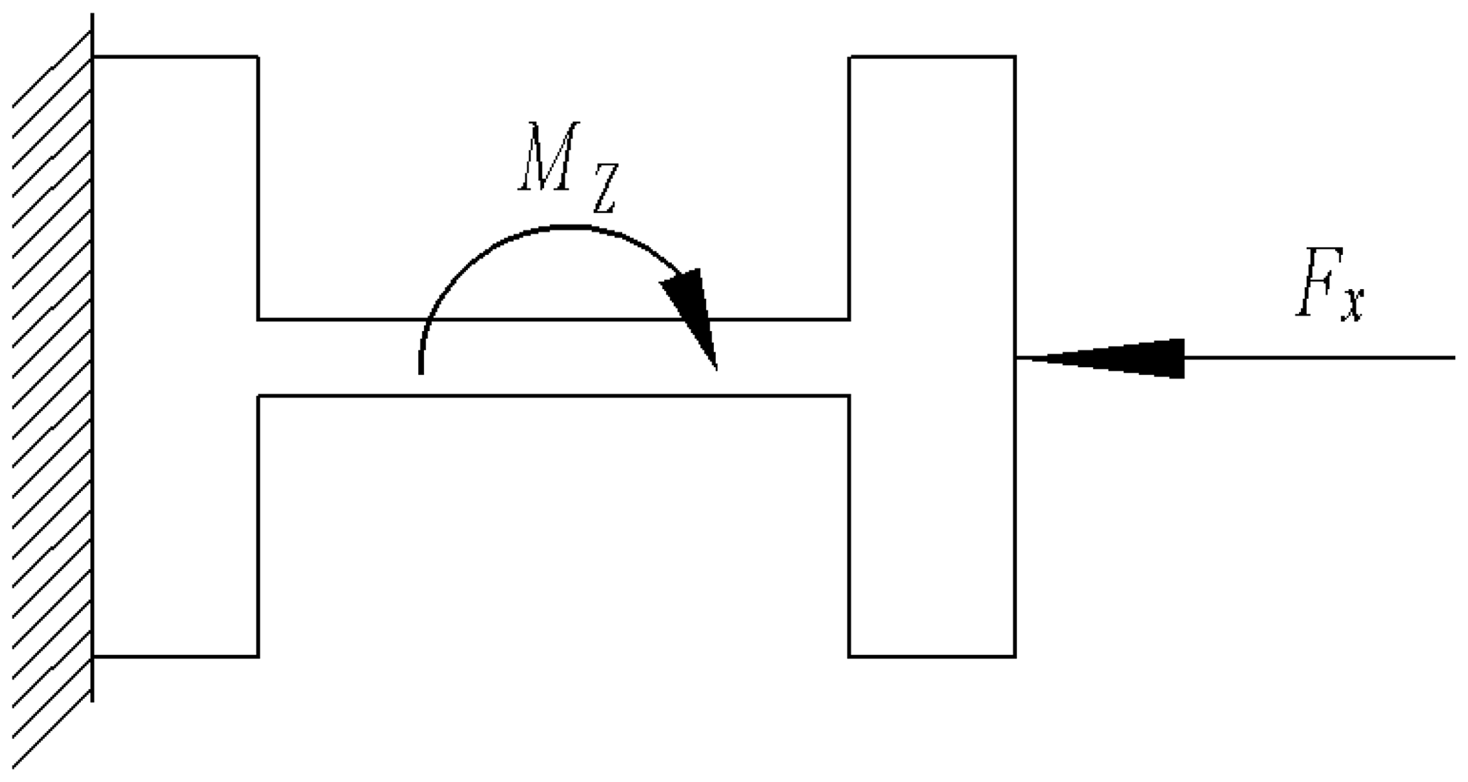
The compliance ratio λ could be defined as follows:
λ reflects the sensitivity of the main form of the output displacement when the flexible hinge is simultaneously driven by Fx and Mz. When λ is larger, the sensitivity of Δx as the main form of the output displacement is higher; otherwise, the sensitivity of αz as the main form of output displacement is higher. In other words, when λ is larger, the axial line displacement Δx of the flexible hinge is more easily generated, and it is more difficult to generate the angle displacement αz around the z axis.
2.2 Parametric analysis of the compliance ratio λ
The four types of commonly used flexible hinges are constant rectangular flexible hinge (CRF), corner-filled flexible hinge (CFF), right circular flexible hinge (RCF), and elliptical flexible hinge (EF). Assume that one end of the flexible hinge is fixed, and the other is free. They are only driven by the axial force Fx and the bending moment Mz. The four types of commonly used flexible hinges are shown in Fig. 2.
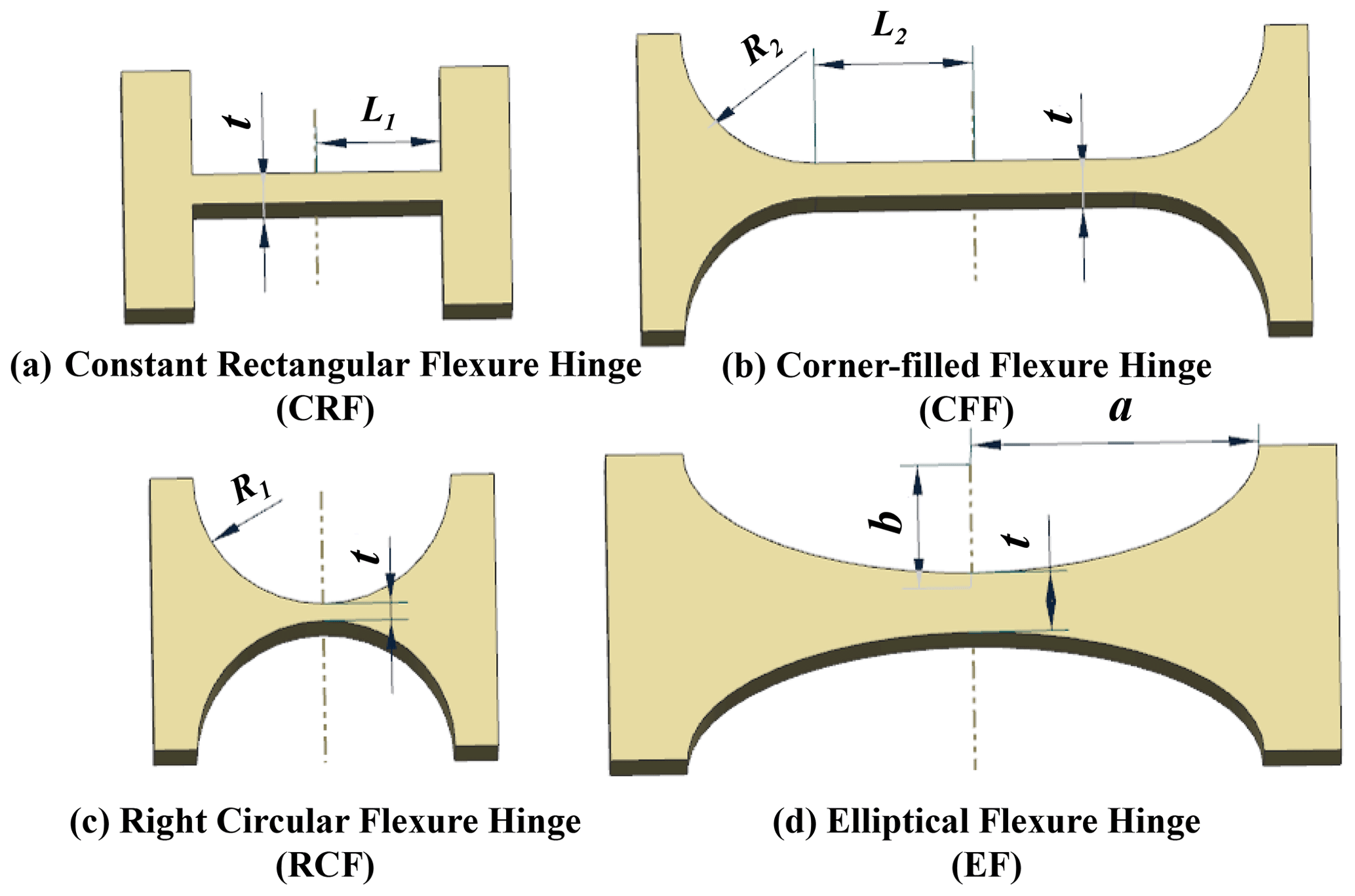
In accordance with the conclusion of the literature (Zhao et al., 2013; Tian et al., 2010; Lu, 2015), the parameter of the minimum cutting thickness t is the most sensitive to the effect of the output displacement. Therefore, it is necessary to obtain the relationship between the compliance ratio λ and the minimum cutting thickness t when the t varies but the notch length keeps constant. All of the structure parameters are as follows: L1=5 mm, L2=4 mm, R2=1 mm, R1=5 mm, a=5 mm, b=3 mm, w=8 mm, and the elastic modulus N m−2. The numerical calculation was programmed by MATLAB, and it is shown in Fig. 3.

The compliance ratios λ of the four types of flexible hinges above are all gradually increasing when t is increasing, which shows that the sensitivity of the Δx as the main form of the output displacement is gradually increasing, and the sensitivity of the αz as the main form of the output displacement is gradually decreasing. In other words, when the compliance ratio λ increased, the main form of the output displacement is gradually transforming the αz to the Δx.
Summarizing Fig. 3, when the t is constant, the compliance ratio λ of CRF and CFF is much less than that of RCF and EF. Therefore, compared to the other two types of flexible hinges, the main form of the output displacement of CRF and CFF is the αz, while RCF and EF are more likely to generate the Δx as the main form. All of these findings are a good guide for selecting and optimizing the type of flexible hinge when designing the compliant actuator mechanism.
3.1 Structure of compliant lever actuator
3.1.1 Stator mechanism
The structure of the compliant lever actuator is shown in Fig. 4a, which illustrated the base body, driving foot, piezoelectric stack, pre-tightening pad, pre-tightening ceramic ball, and pre-tightening screw. The stator was machined by wire electrical discharge machining (WEDM) with the material of 45 steel. The stator was developed based on the principle of lever amplification. The two piezoelectric stacks were arranged vertically with each other so that they could generate the displacement in the orthogonal directions when they were excited by the power. The displacement of the piezoelectric stacks was amplified at the driving foot by making use of the lever mechanism and the bending deformation mechanism of the RCF. Consequently, the mover could be driven by the friction of the driving foot. In order to avoid the instability and discontinuity of single driving foot, the double driving feet were proposed, which is shown in Fig. 4b.
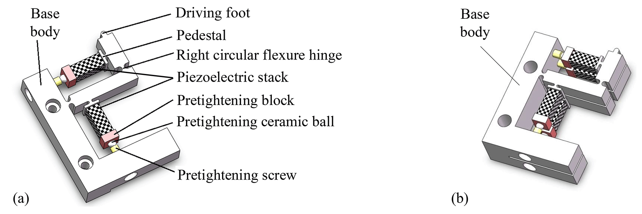
Figure 4Diagram of stator. (a) Structure of stator with single driving foot and (b) structure of stator with double driving feet.
3.1.2 Pre-tightening mechanism
The pre-tightening mechanism is shown in Fig. 5. The main function of the pre-tightening mechanism is to ensure the sufficient pre-tightening force between the double driving feet and the ceramic friction disk on the linear guide. The pre-tightening mechanism adopted the elastic mechanism. The pre-tightening spring could be compressed by the pre-tightening adjusting column, and it could also be fixed by the locking screw. The pre-tightening force could be transmitted to the stator mechanism through the pre-tightening block. The pre-tightening mechanism can ensure that the pre-tightening force is sufficient while limiting its lateral swing degree of freedom. Therefore, stability and continuity of the double driving feet mechanism could be improved greatly.
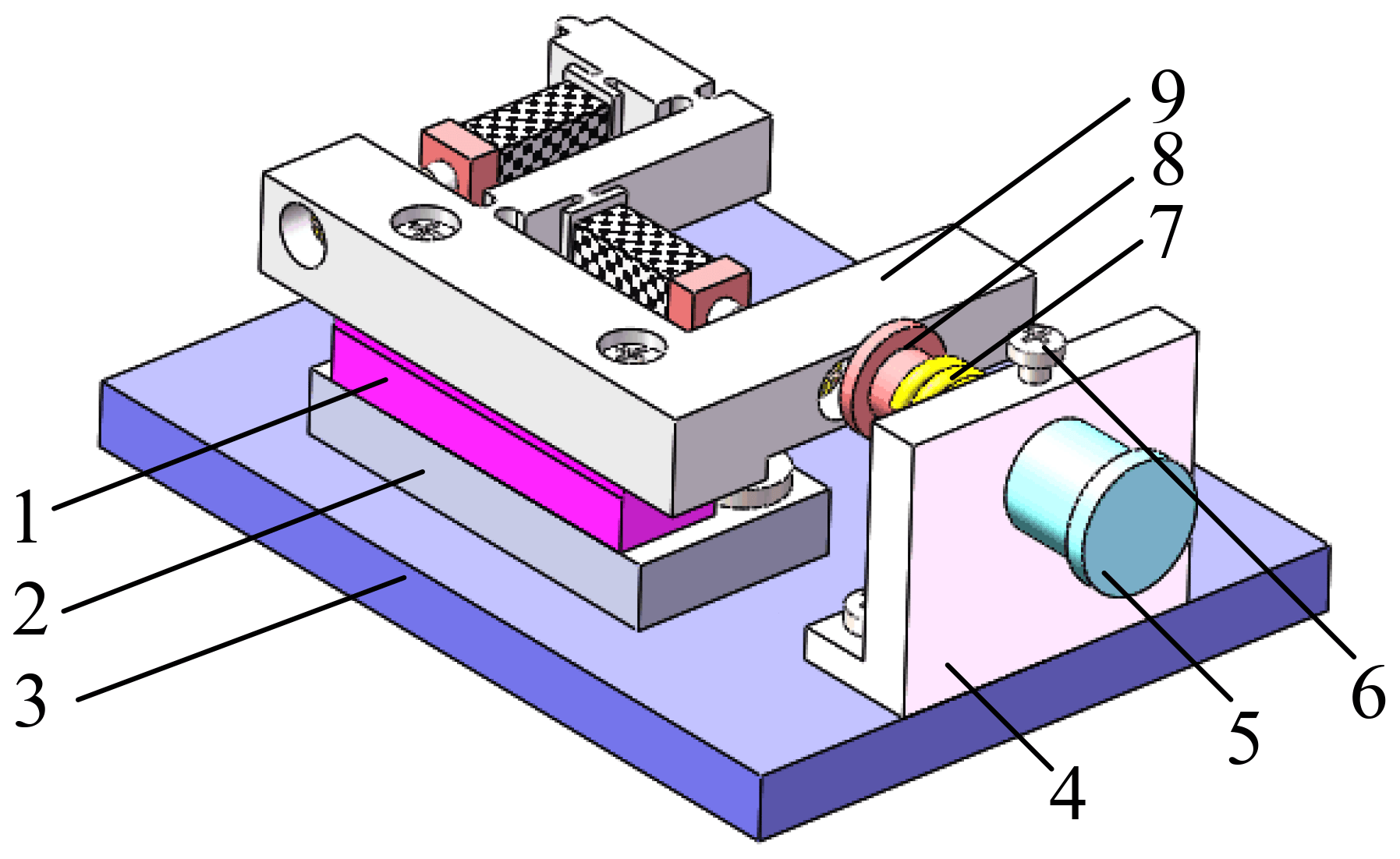
Figure 5Diagram of pre-tightening mechanism: (1) slideway, (2) padding block, (3) baseplate, (4) pre-tightening supporting plate, (5) pre-tightening adjusting column, (6) locking screw (7) pre-tightening spring, (8) pre-tightening block, and (9) stator with double driving feet.
3.2 Principle analysis of the compliant lever actuator
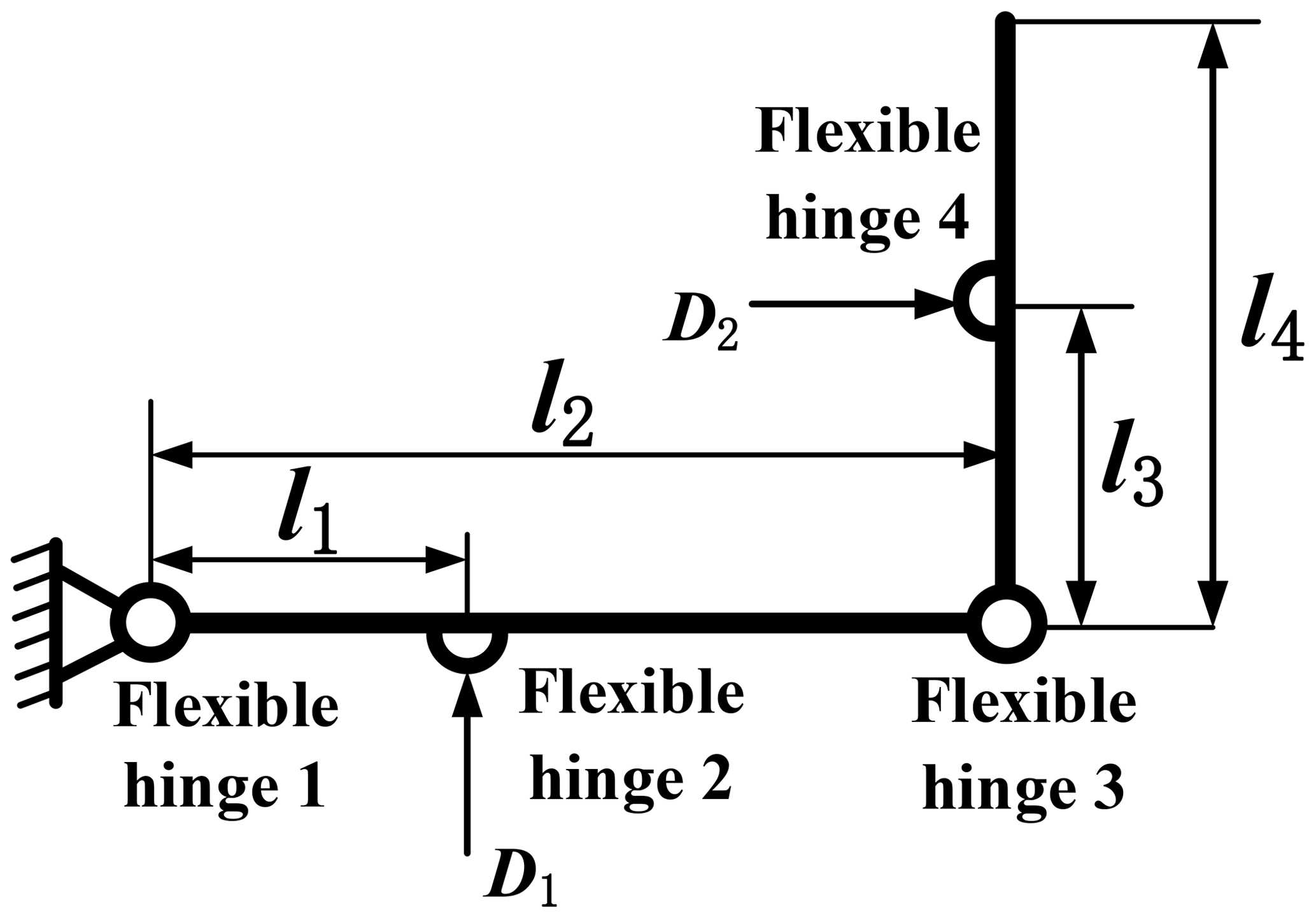
The proposed compliant lever actuator that is shown in Fig. 4 could be simplified as the geometric model that is shown in Fig. 6. D1 and D2 are the output displacement of the two piezoelectric stacks that were excited by the driving power. The whole force analysis diagram of the compliant lever mechanism is shown in Fig. 7.
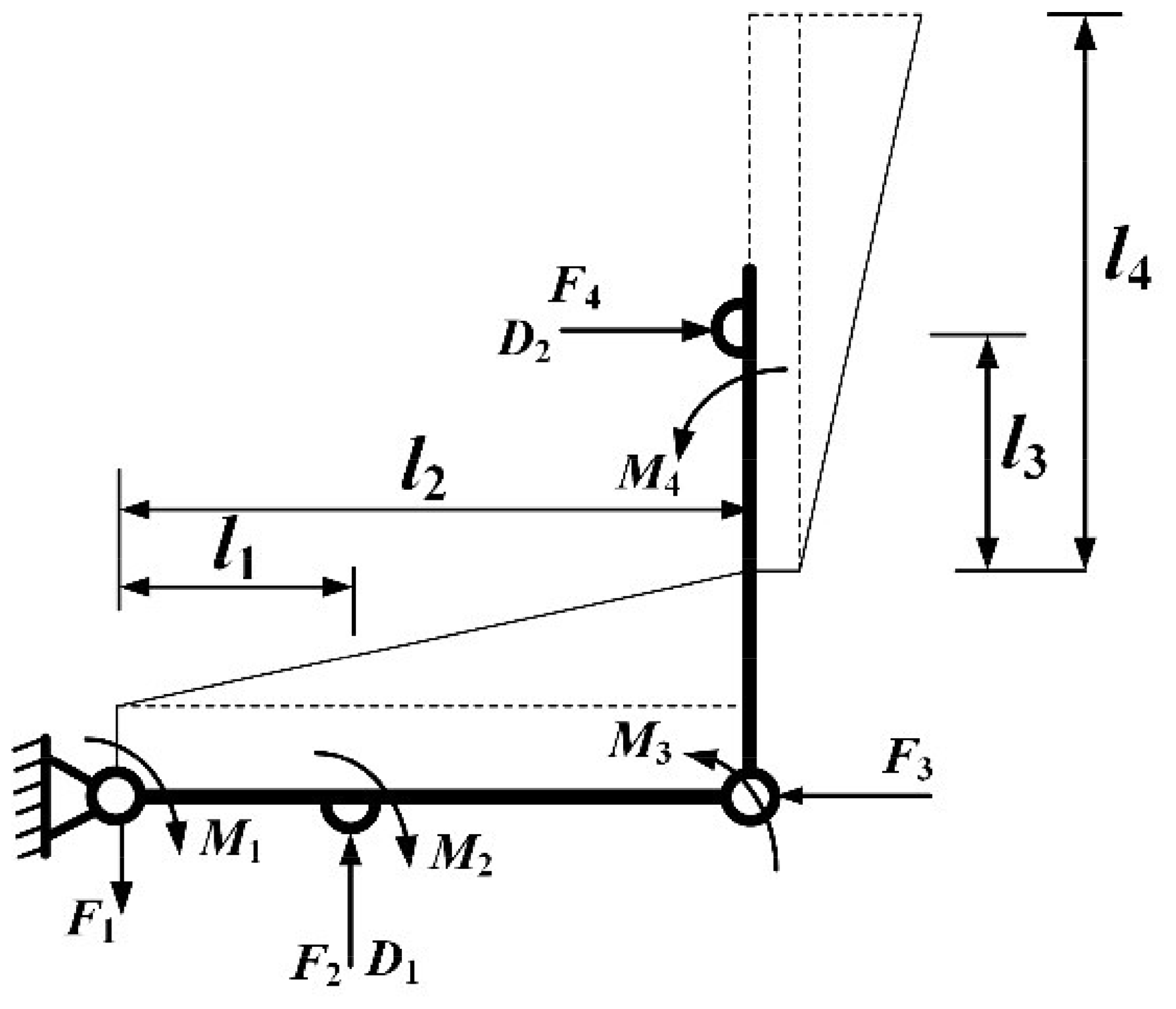
The flexible hinge could generate angular deformation, stretching deformation, and compression deformation during the motion of the compliant lever mechanism, and the turning center of flexible hinges may be deviated, which could result in affecting the magnification ratio of the compliant lever mechanism.
The order is as follows: Fi is the axial force that acted on the flexible hinge i; Mi is the torque that acted on the flexible hinge i; Δi is the axial deformation of the flexible hinge i; αi is the rotation angle of the flexible hinge i.
Then, there is the relationship between the variables above:
where CF is the axial tensile flexibility coefficient; CM is the rotation flexibility coefficient.
According to the principle of force balance from Fig. 7, the force balance relationship is as follows:
Assuming that θ1 is the rotation angle of the horizontal lever, and θ2 is the rotation angle of the vertical lever,
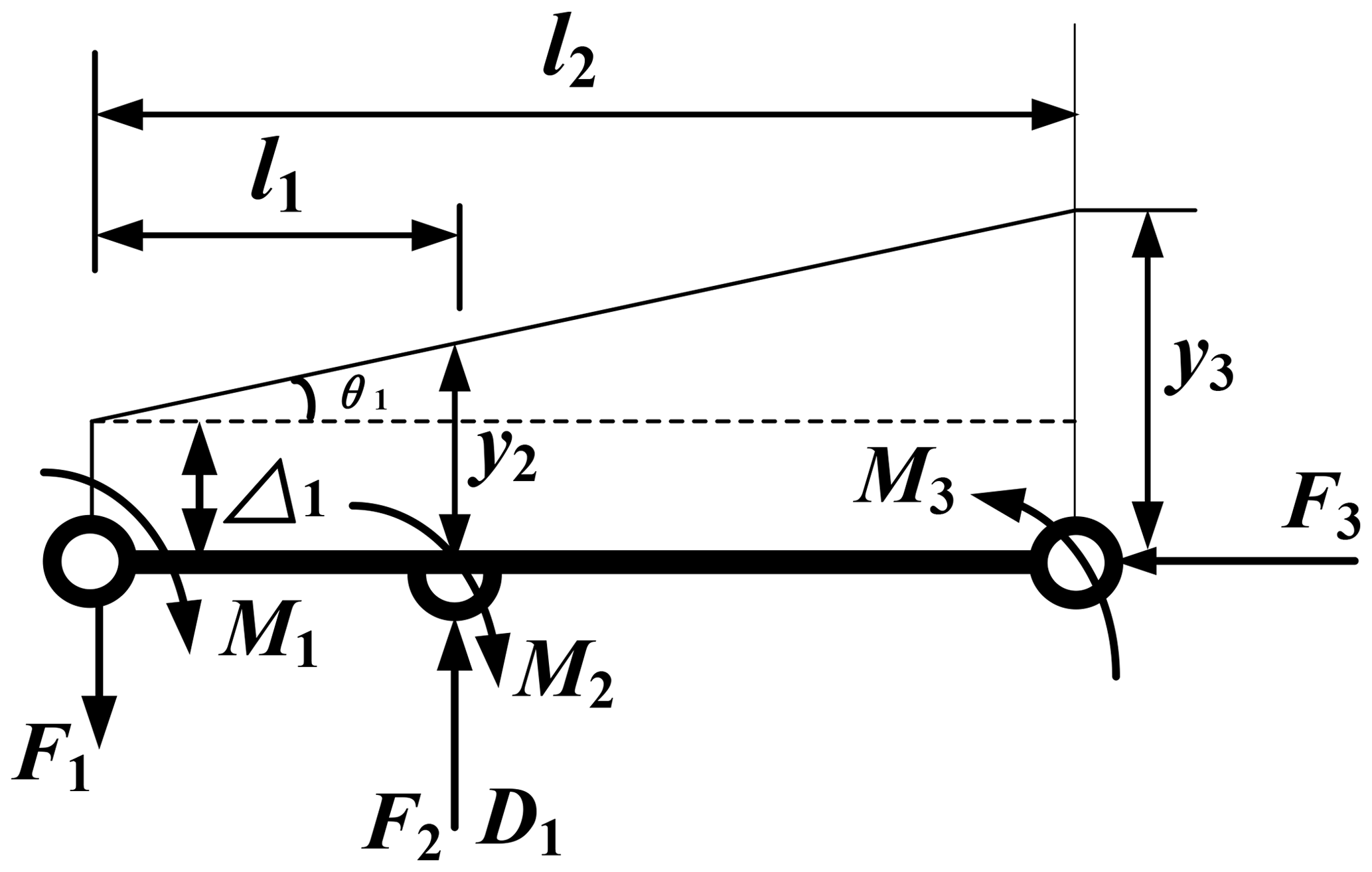
In the motion of the horizontal lever mechanism, the horizontal lever actually rotated around the rotating center of the flexible hinge 1, and the following relationship can be obtained from Fig. 8:
Because of that D1 is the output displacement of the piezoelectric stack; that is to say, the input displacement of the horizontal lever mechanism was D1. The D1 was acted on the axial direction of the flexible hinge 2, which would generate the compression deformation Δ2; at the same time, the rotation center of the flexible hinge 1 was deviated as Δ1. Therefore, the actual effective input displacement y2 of the horizontal lever mechanism could be obtained as follows:
The actual output displacement y3 of the horizontal lever mechanism could be obtained as follows:
The rotation angle θ1 of the horizontal lever mechanism is as follows:
Consequently, the magnification ratio k1 of the horizontal lever mechanism is as follows:
In the axial direction of the flexible hinge 2, the flexible hinge 2 will be compressed by the axial force, and the compression amount is Δ2. At the same time, the rotation center of the flexible hinge 1 is offset, and the displacement is assumed to be Δ1; then the actual effective input displacement of the lateral flexible lever mechanism is described below.
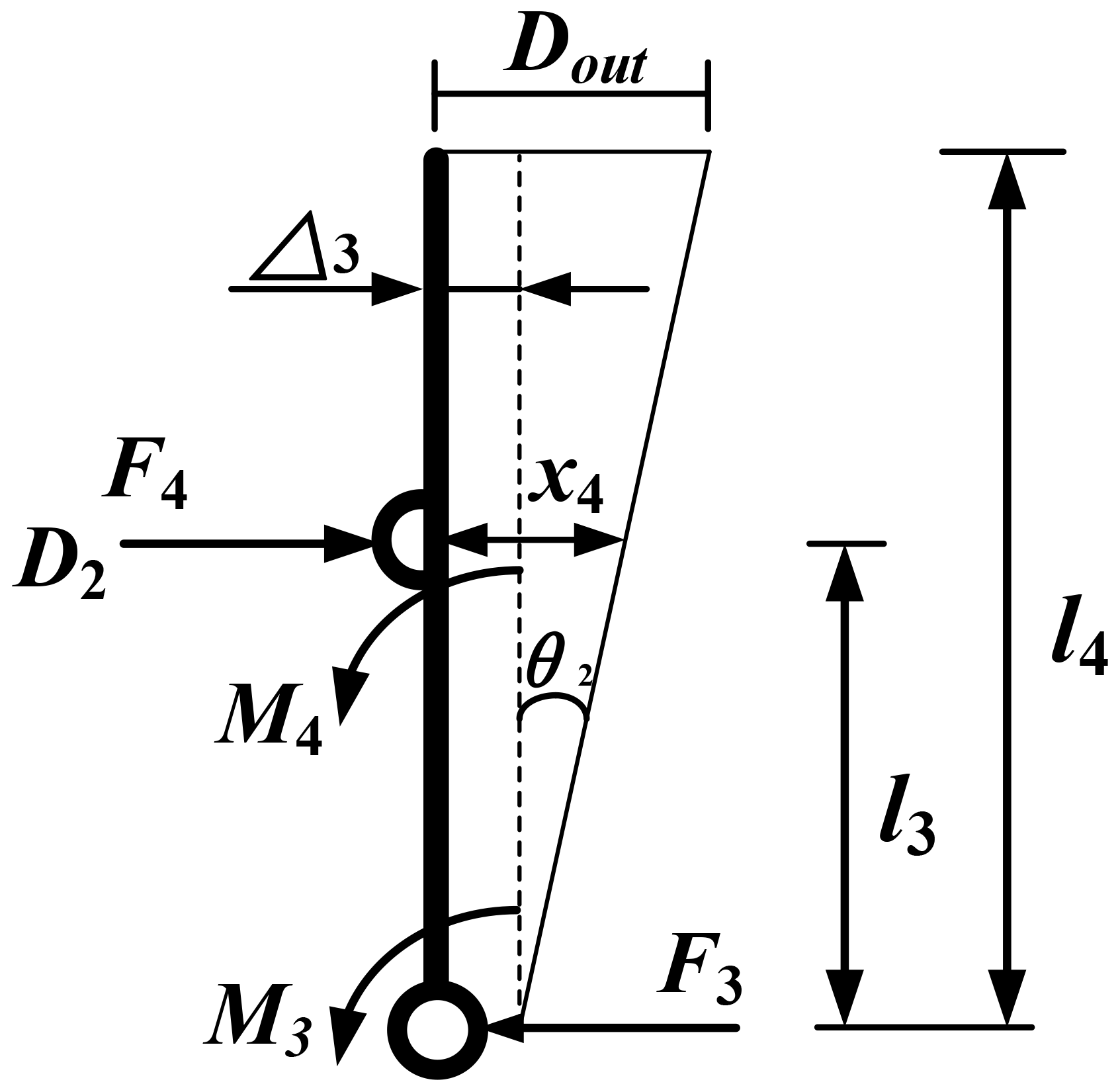
In the motion of the vertical lever mechanism, the vertical lever actually rotated around the rotating center of the flexible hinge 3, and the following relationship can be obtained from Fig. 9:
Because of that D2 is the output displacement of the piezoelectric stack; that is to say, the input displacement of the vertical lever mechanism was D2. The D2 was acted on the axial direction of the flexible hinge 4, which would generate the compression deformation Δ4; at the same time, the rotation center of the flexible hinge 3 was deviated as Δ3. Therefore, the actual effective input displacement x4 of the vertical lever mechanism could be obtained as follows:
The actual output displacement Dout of the vertical lever mechanism could be obtained as follows:
The rotation angle θ2 of the vertical lever mechanism is as follows:
Consequently, the magnification ratio k2 of the vertical lever mechanism is as follows:
In summary, the magnification ratio k1 and k2 could be obtained from Eqs. (2)–(19) as follows:
Taking Eq. (1) into Eqs. (2)–(21) above, the magnification ratios k1 and k2 based on the compliance ratio λ are as follows:
From Eqs. (22) and (23), it is found that the magnification ratios k1 and k2 of the compliant lever mechanism are only related to the compliance ratio λ and the geometry parameters of itself. Once the lever compliant mechanism structure is determined, the different types of flexible hinges would affect the magnification ratio of the compliant lever mechanism dramatically.
3.3 Optimization of the compliant lever actuator
According to the analysis of the compliance ratio λ from Fig. 3, it can be seen that under the same geometry parameters and forces, the output rotation angle of the CRF is larger than that of the RCF. The input displacement could be amplified mainly because of the fact that the lever rotates around the turning center of hinge 1 and 3, respectively. Therefore, the magnification ratio of the compliant lever mechanism could increase dramatically by replacing the RCF instead of the CRF at flexible hinges 1 and 3. The optimized compliant lever mechanism is shown in Fig. 10. The geometry parameters were given based on experience as shown in Table 1.
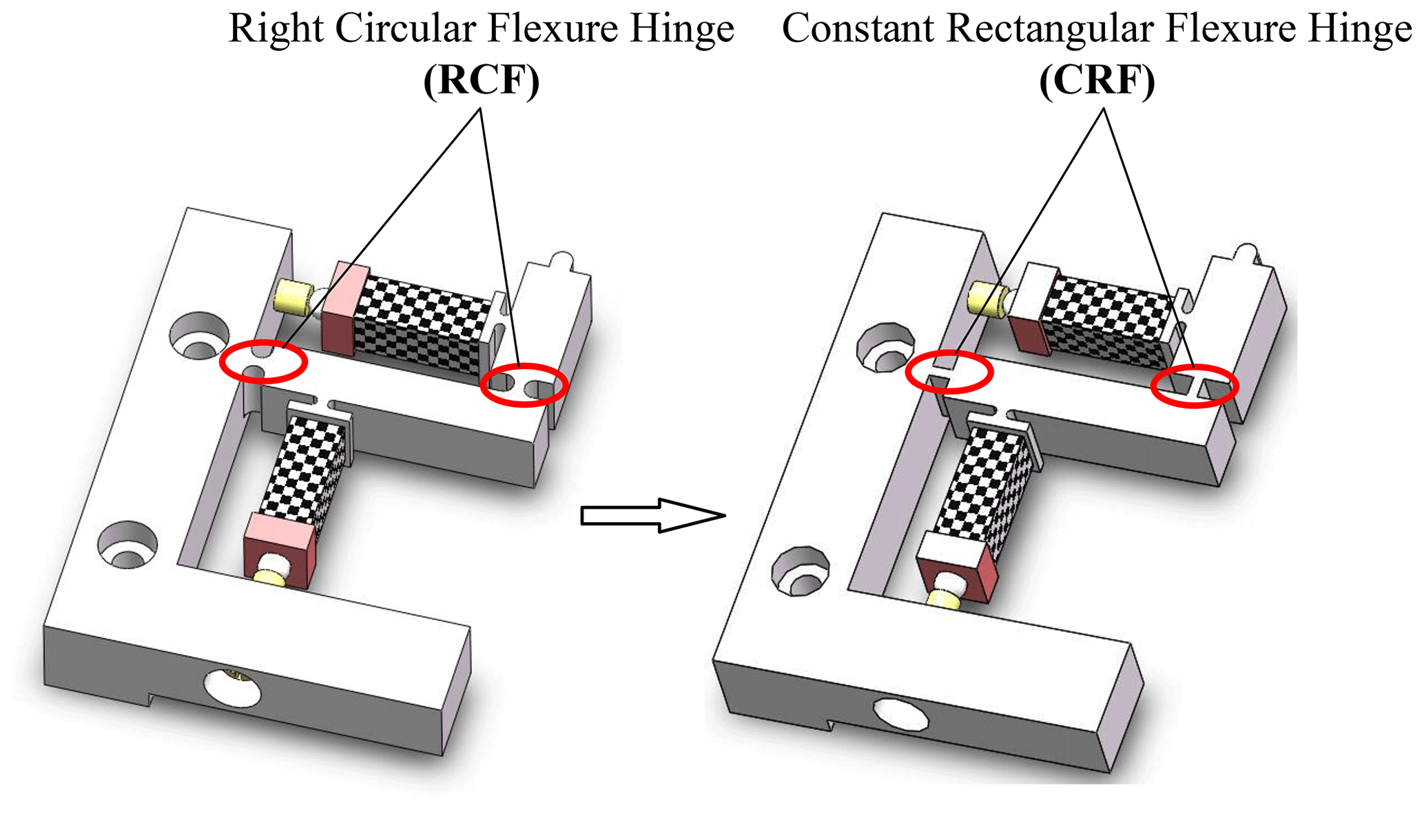
Table 1Geometry of the compliant actuator based on experience.

In Table 1, l1 means the distance between the displacement input point of the horizontal lever mechanism and the center fulcrum; l2 means lever length of horizontal lever mechanism; l3 means the distance between the displacement input point of the vertical lever mechanism and the center fulcrum; l4 means lever length of vertical lever mechanism; t means the minimum cutting thickness of flexible hinges; L means the incision length of the flexible hinge; w means the width of the flexible hinge.
The tensile flexibility coefficient CF and the rotational flexibility coefficient CM of the RCF and the CRF could be obtained from the literature (Bolzmacher et al., 2010; Ma et al., 2006; Xu and Li, 2011); then the compliance ratio λ could be obtained from Eqs. (23) and (24). Therefore, the magnification ratio k1 and k2 of the compliant lever mechanism based on the RCF and the CRF could be calculated. Before optimization, the magnification ratio k1 and k2 of the compliant lever mechanism based on the RCF was that k1=2.866 and k2=2.094. After optimization, the magnification ratio k1 and k2 of the compliant lever mechanism based on the CRF was k1=3.099 and k2=2.404, respectively. The magnification ratio k1 and k2 was increased by 8.18 % and 12.56 %, which proved that the optimization based on the structure parameters of flexible hinge was feasible and effective.
4.1 Finite element analysis (FEA) simulation
The FEA software ANSYS was used to simulate and verify the optimization. The FEA is correlated with the test (Chen et al., 2021, 2018). The material of the compliant lever mechanism was chosen as steel, and the modulus of elasticity is 209 GPa, the Poisson ratio is 0.29, and the yield stress limit is 355 MPa. The initial input displacement was as follows: D1=0.01 mm and D2=0.01 mm. The simulation results are shown in Figs. 11 and 12.
The simulation results show that before optimization, the magnification ratio k1 and k2 of the compliant lever mechanism based on the RCF is k1=2.866 and k2=2.094, respectively. The errors between the simulation results and the calculation results are 8.48 % and 3.97 %. After optimization, the magnification ratio k1 and k2 of the compliant lever mechanism based on the CRF is k1=3.099 and k2=2.404, respectively. The errors between the simulation results and the calculation results are 8.43 % and 6.04 %. The magnification ratio k1 and k2 of the compliant lever mechanism was increased by 8.13 % and 14.80 % from the FEA simulation results.
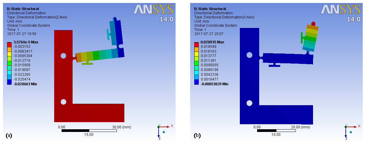
Figure 11The magnification ratio k1 and k2 of the compliant lever mechanism based on the RCF. (a) Displacement diagram of k1; (b) displacement diagram of k2.
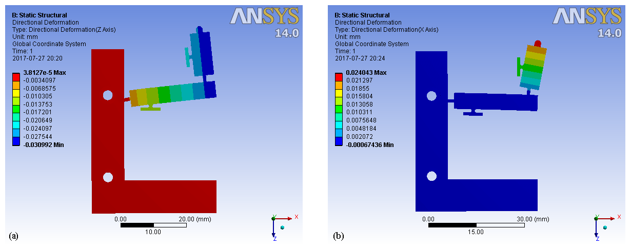
Figure 12The magnification ratio k1 and k2 of the compliant lever mechanism based on the CRF. (a) Displacement diagram of k1; (b) displacement diagram of k2.
4.2 Experiment verification
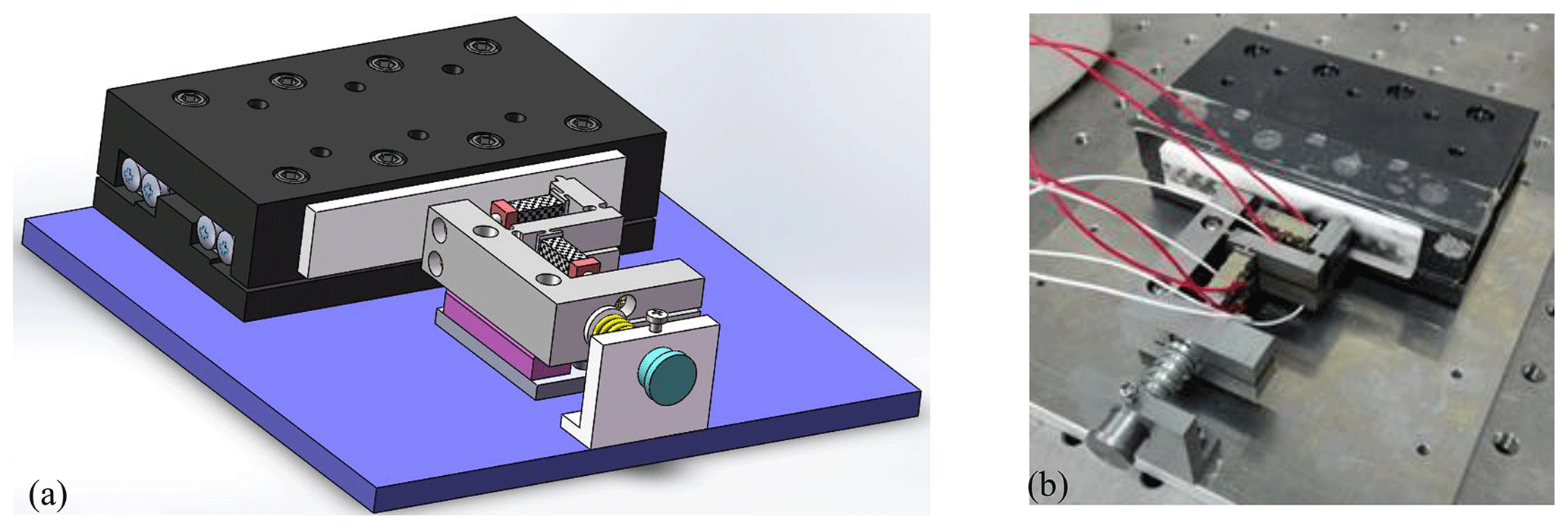
The experimental measurement system mainly consists of a signal excitation system, an actuator drive system, a laser measurement system, and a PC data acquisition system. The laser measurement system was selected by the LK-H020 of Keyence company, and its measurement accuracy is 0.02 µm. The experimental measurement system is shown in Fig. 13, and the specimens of the compliant lever mechanism based on the RCF and the CRF are shown in Fig. 14.
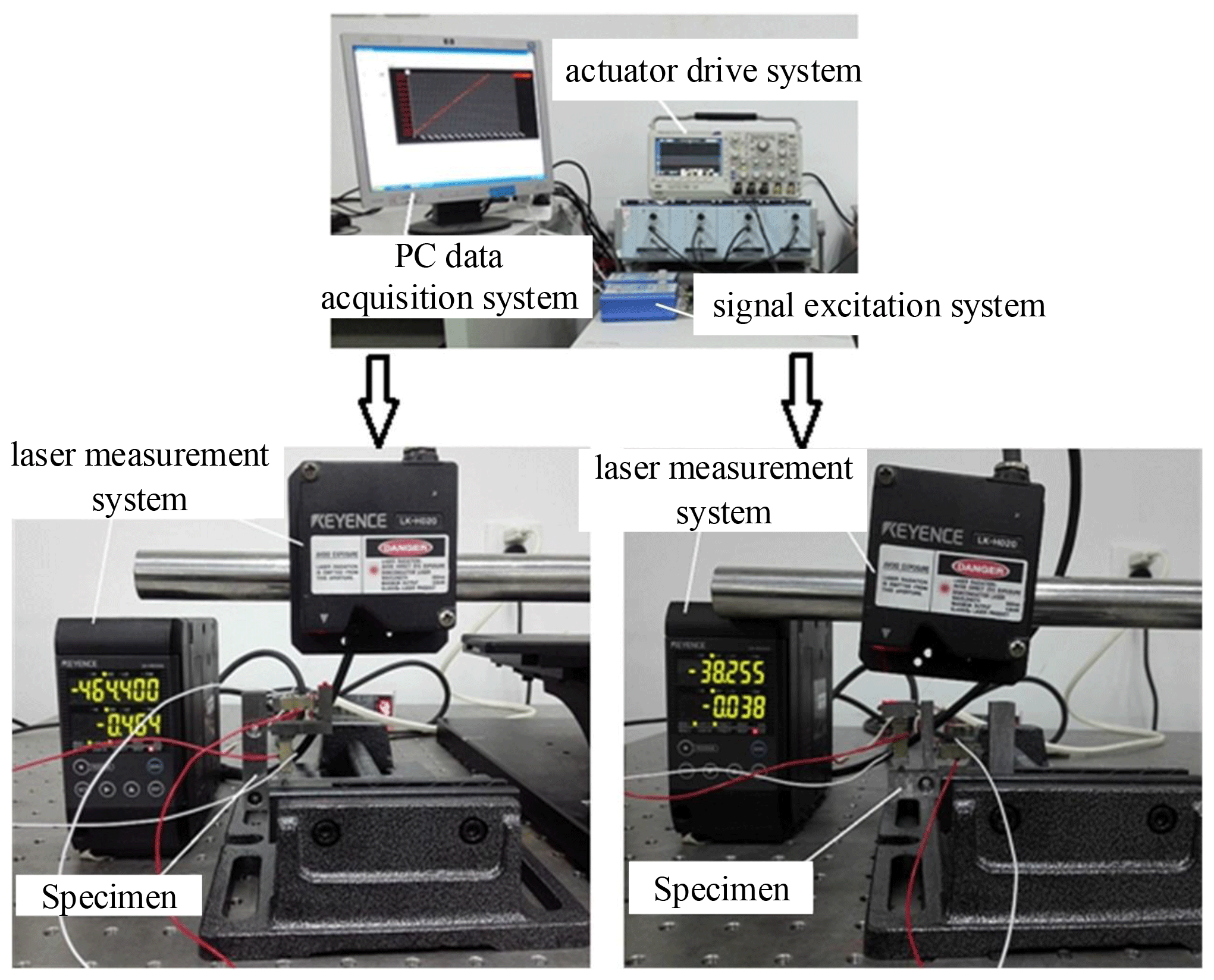
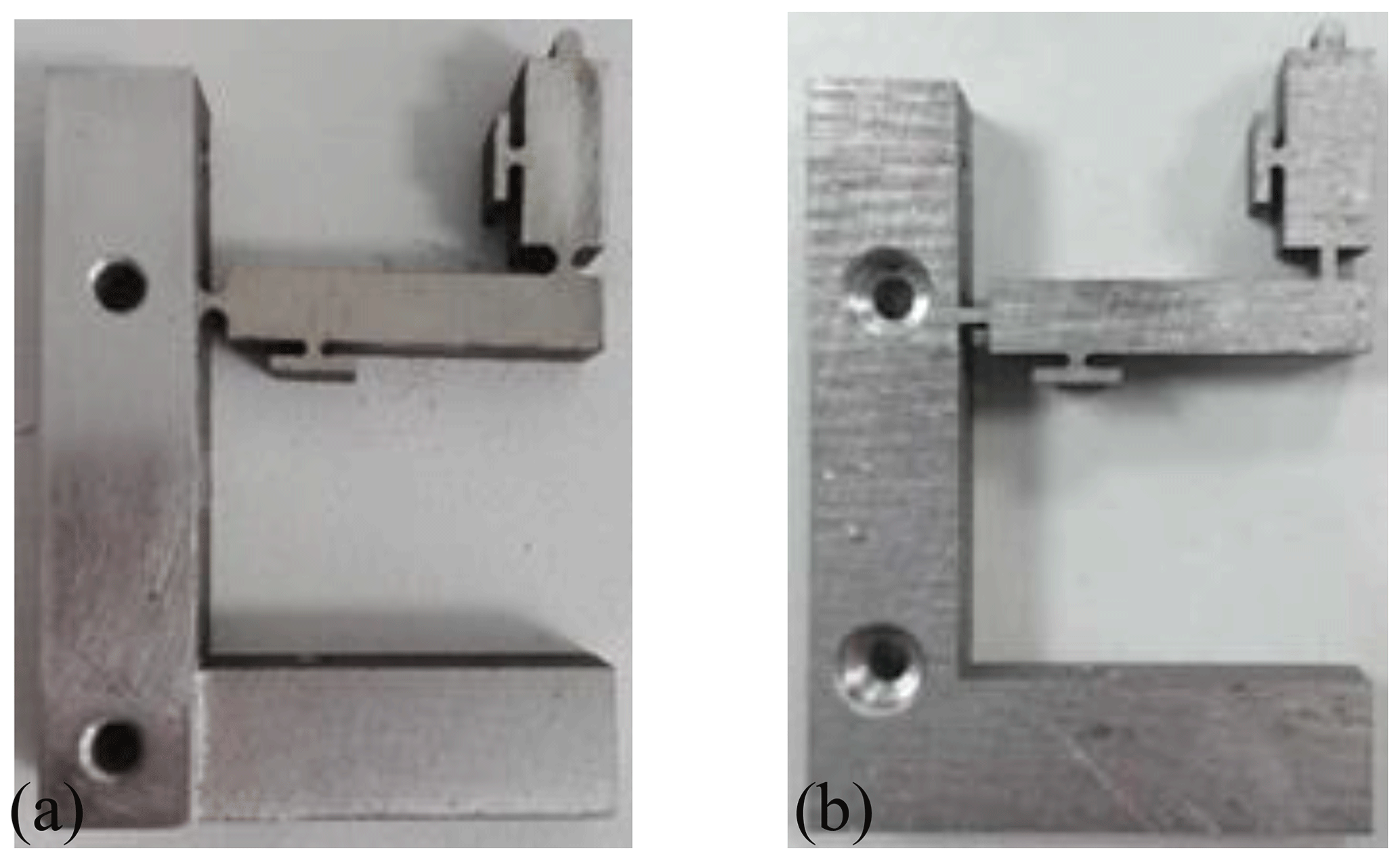
Figure 14Specimen of the compliant lever mechanism based on the RCF and the CRF. (a) Specimen based on the RCF. (b) Specimen based on the CRF.

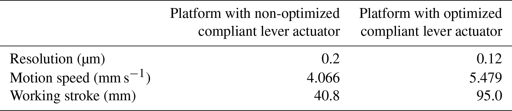
Table 3Key performance of the precision linear positioning platform.
The origin experiment condition was set as follows: the peak voltage was 100 V, the frequency of the voltage was 100 Hz, the preload was 40 N, and the output displacement of the piezoelectric stack was 8 µm. The output displacement of the horizontal lever mechanism was 22.591 µm and that of the vertical lever mechanism was 17.025 µm, so the magnification ratio k1 and k2 could be calculated, which was k1=2.824 and k2=2.128. While after optimization, under the same experiment condition, the output displacement of the horizontal and the vertical lever mechanism was 24.544 and 19.184 µm, respectively. Therefore, the magnification ratio k1 and k2 could be obtained by calculating, and the results was as follows: k1=3.068 and k2=2.398.
4.3 Discussion
According with the analysis of the structure parameter λ, the magnification ratio of the compliant lever mechanism based on the CRF was enlarged more than that of the compliant lever mechanism based on the RCF. The theoretical calculation results, FEA simulation results, and the experiment results all proved that. Table 2 compares the three verification methods.
The optimization ratios of the horizontal and the vertical lever mechanism of the three verification methods were 8.13 %–8.64 % and 12.56 %–14.80 %, respectively. It has shown that the optimization of the compliant actuator based on the compliance parameter ratio λ is feasible and effective.
In order to validate the effectiveness of the optimization design on compliant actuator based on compliance features of flexible hinges, it is necessary to study the experiment performance. The compliant lever actuator was used to drive the linear guide directly. The precision linear positioning platform is shown in Fig. 15. The experiment system is the same as that mentioned above. Table 3 shows the key performance of the precision linear positioning platform that used the non-optimized and the optimized compliant actuators.
The experiment data in Table 3 show that the performance of the linear positioning platform with the optimized compliant lever actuator is much better than that of the platform with the non-optimized compliant lever actuator. Compared with the non-optimized one, the optimized one has different degrees of optimization in terms of the resolution, motion speed, and the working stroke.
-
Based on the flexibility coefficient (CM and CF) of flexible hinges, a new parameter, the compliance ratio λ, was proposed, which reflected the sensitivity of the main output displacement form of the flexible hinge. By analyzing the relationship between the minimum cutting thickness t and the compliance ratio λ, it could find that the sensitivity of the rotational angular displacement αz of CRF and CFF is higher than that of the RCF and EF, and the sensitivity of the axial line displacement Δx of the RCF and EF is higher than that of the CRF and CFF.
-
A compliant lever actuator based on the flexible hinges was established, and the displacement magnification ratio of the compliant lever actuator was derived theoretically, by combining with the fact that the rotation center of flexible hinges could deviate under the external force, and the correctness of the theoretical guidance was also proved.
-
The optimization of the lever actuator was carried out based on the compliance features analysis of the commonly used flexible hinges. The correctness and effectiveness of the optimization were both proved by the consistency of the theoretical calculation, simulation results, and the experiment data.
-
The application of the precision linear positioning platform shows that the optimized actuator has different degrees of optimization in terms of the key performance, including the resolution, the motion speed, and the working stroke.
In the high-precision and ultra-high-precision positioning system, the positioning accuracy caused by the magnification ratio would have a great influence on the performance of the positioning system. The proposed analysis method based on the compliance features of the flexible hinge provides a new idea for the design of compliant actuators or compliant mechanism with different types of flexible hinges.
All data included in this study are shown in the relevant figures and tables in the article.
QL proposed the plan and wrote the article; CW processed and manufactured the experimental device and completed the experiment; KZ was responsible for theoretical analysis and finite element analysis; HG searched for information and revised the article.
The authors declare that they have no conflict of interest.
Publisher's note: Copernicus Publications remains neutral with regard to jurisdictional claims in published maps and institutional affiliations.
This work was supported by Natural Science Research Projects in Jiangsu Higher Education Institutions (grant nos. 17KJB140028 and 18KJB460030) and the National Natural Science Foundation of China (grant no. 51805465).
This paper was edited by Dongming Gan and reviewed by four anonymous referees.
Bi, S., Zhao, S., and Zhu, X.: Dimensionless design graphs for three types of annulus-shaped flexure hinges, Precis. Eng., 34, 659–666, https://doi.org/10.1016/j.precisioneng.2010.01.002, 2010.
Bolzmacher, C., Bauer, K., Schmid, U., Hafez, M., and Seidel, H.: Displacement amplification of piezoelectric microactuators with a micromachined leverage unit, Sensor Actuat. A-Phys., 157, 61–67, https://doi.org/10.1016/j.sna.2009.10.014, 2010.
Chen, Y., Joffre, D., and Avitabile, P.: Underwater Dynamic Response at Limited Points Expanded to Full-Field Strain Response, J. Vib. Acoust., 140, 051016, https://doi.org/10.1115/1.4039800, 2018.
Chen, Y., Mendoza, A. S. E., and Griffith, D. T.: Experimental and numerical study of high-order complex curvature mode shape and mode coupling on a three-bladed wind turbine assembly, Mech. Syst. Signal Pr., 160, 107873, https://doi.org/10.1016/j.ymssp.2021.107873, 2021.
Choi, K.-B., Lee, J. J., and Hata, S.: A piezo-driven compliant stage with double mechanical amplification mechanisms arranged in parallel, Sensor Actuat. A-Phys., 161, 173–181, https://doi.org/10.1016/j.sna.2010.05.027, 2010.
Gong, J.: Closed Loop Design Method of Micro-driving Displacement Amplifier Module Targeting for Stiffness, J. Mech. Eng., 48, 58–64, https://doi.org/10.3901/jme.2012.15.058, 2012.
Gong, J., Zhang, Y., and Hu, G.: Stiffness analysis of micro-driving displacement amplifier module considering complex deformation of all flexible structure units, J. Beijing Univ. Tech., 39, 1791–1797, https://doi.org/10.11936/bjutxb2013121791, 2013.
Li, Q., Wang, D., and Li, Y.: Design of Modern Precision Instruments, Tsinghua University Press, China, 2004.
Li, W., Ye, G., and Wang, Y.: Study of properties of a kind of bridge-type micro-displacement mechanism, J. China Univ. Mining & Tech., 40, 310–314, https://doi.org/10.1016/S1872-5805(11)60064-4, 2011.
Liu, Q.: Study on the performance analysis methods of the compliant symmetric micro-displacement magnifying mechanism, Chin. J. Eng. Des., 20, 344–347, https://doi.org/10.3785/j.issn.1006-754X.2013.04.015, 2013.
Lobontiu, N.: Compliance-based matrix method for modeling the quasi-static response of planar serial flexure-hinge mechanisms, Precis. Eng., 38, 639–650, https://doi.org/10.1016/j.precisioneng.2014.02.014, 2014.
Lobontiu, N. and Cullin, M.: In-plane elastic response of two-segment circular-axis symmetric notch flexure hinges: The right circular design, Precis. Eng., 37, 542–555, https://doi.org/10.1016/j.precisioneng.2012.12.007, 2013.
Lu, Q.: Optimization Design of Flexible Micro-Displacement Amplification Mechanism Based on Parameters, J. Appl. Sci. Eng., 18, 345–354, https://doi.org/10.6180/jase.2015.18.4.05, 2015.
Ma, H.-W., Yao, S.-M., Wang, L.-Q., and Zhong, Z.: Analysis of the displacement amplification ratio of bridge-type flexure hinge, Sensor Actuat. A-Phys., 132, 730–736, https://doi.org/10.1016/j.sna.2005.12.028, 2006.
Qi, H., Zhang, B., Zhang, N., Zheng, M., and Chen, Y.: Enhanced Lateral and Roll Stability Study for a Two-Axle Bus via Hydraulically Interconnected Suspension Tuning, SAE International Journal of Vehicle Dynamics, Stability, and NVH, 3, 5–18, https://doi.org/10.4271/10-03-01-0001, 2018.
Qi, H., Chen, Y., Zhang, N., Zhang, B., Wang, D., and Tan, B.: Improvement of both handling stability and ride comfort of a vehicle via coupled hydraulically interconnected suspension and electronic controlled air spring, P. I. Mech. Eng. D-J. Aut., 234, 552–571, https://doi.org/10.1177/0954407019856538, 2019.
Shen, J., Zhang, H., and Zhao, Y.: Calculation method of magnification ratio for lever-type flexible hinge mechanism driven by piezoactuator, Trans. Chin. Soc. Agri. Mach., 44, 267–271, https://doi.org/10.6041/j.issn.1000-1298.2013.09.046, 2013.
Tan, B., Wu, Y., Zhang, N., Zhang, B., and Chen, Y.: Improvement of ride quality for patient lying in ambulance with a new hydro-pneumatic suspension, Adv. Mech. Eng., 11, 1–20, https://doi.org/10.1177/1687814019837804, 2019.
Tian, Y., Shirinzadeh, B., Zhang, D., and Zhong, Y.: Three flexure hinges for compliant mechanism designs based on dimensionless graph analysis, Precis. Eng., 34, 92–100, https://doi.org/10.1016/j.precisioneng.2009.03.004, 2010.
Wang, M., Zhang, B., Chen, Y., Zhang, N., and Zhang, J.: Frequency-Based Modeling of a Vehicle Fitted With Roll-Plane Hydraulically Interconnected Suspension for Ride Comfort and Experimental Validation, IEEE Access, 8, 1091–1104, https://doi.org/10.1109/access.2019.2935260, 2020.
Xu, Q.: Design, testing and precision control of a novel long-stroke flexure micropositioning system, Mech. Mach. Theory, 70, 209–224, https://doi.org/10.1016/j.mechmachtheory.2013.07.016, 2013.
Xu, Q. and Li, Y.: Analytical modeling, optimization and testing of a compound bridge-type compliant displacement amplifier, Mech. Mach. Theory, 46, 183–200, https://doi.org/10.1016/j.mechmachtheory.2010.09.007, 2011.
Yu, Y.-Q., Feng, Z.-L., and Xu, Q.-P.: A pseudo-rigid-body 2R model of flexural beam in compliant mechanisms, Mech. Mach. Theory, 55, 18–33, https://doi.org/10.1016/j.mechmachtheory.2012.04.005, 2012.
Zhao, L., Gong, Y., and Hua, Y.: Compliance Matrix Analysis of Corner-filleted Flexible hinge, China Mech. Eng., 24, 2462–2468, https://doi.org/10.3969/j.issn.1004-132X.2013.18.010, 2013.
Zhu, Z., Luo, S., Feng, Q., Chen, Y., Wang, F., and Jiang, L.: A hybrid DIC–EFG method for strain field characterization and stress intensity factor evaluation of a fatigue crack, Measurement, 154, 107498, https://doi.org/10.1016/j.measurement.2020.107498, 2020.
- Abstract
- Introduction
- Compliance feature analysis of flexible hinges
- Optimization on compliant actuator based on compliance features of flexible hinges
- Verification
- Application
- Conclusion
- Data availability
- Author contributions
- Competing interests
- Disclaimer
- Financial support
- Review statement
- References