the Creative Commons Attribution 4.0 License.
the Creative Commons Attribution 4.0 License.
 | 06 Aug 2021
Dynamic characterization of controlled multi-channel semi-active magnetorheological fluid mount
Mingzhong Wu
In this paper, a novel structure of a controlled multi-channel semi-active magnetorheological (MR) fluid mount is proposed, including four controlled channels and one rate-dip channel. Firstly, the magnetic circuit analysis, rate-dip channel optimization design, and MR fluid mount damping analysis are given. Secondly, the mathematical model of the controlled multi-channel semi-active MR fluid mount is constructed. We analyze the effect of controlled multi-channel closing on the dynamic characteristics of the mounts and the effect of the presence or absence of the rate-dip channel on the low-frequency isolation of the mount. Finally, the controlled multi-channel semi-active MR fluid mount was applied to the vehicle model (a model consisting of an engine, a single engine mount, a single suspension and a vehicle frame), with the transmissibility of the engine relative to the vehicle frame at low frequency and the transmissibility of the engine reciprocating unbalanced force to the vehicle frame magnitude at high frequency as the evaluation index.
Numerical simulation shows the following points. (1) The controllable multi-channel semi-active MR fluid mount can achieve adjustable dynamic stiffness and damping with applied 2 A current to different channels. (2) With known external excitation source, applied currents to different controllable channels can achieve the minimum transmissibility and meet the mount wide-frequency vibration isolation requirement, while adding a rate-dip channel can improve the low-frequency vibration isolation performance of the MR fluid mount. (3) Switching and closing different controllable channels in the vehicle model can achieve the minimum transmissibility of low-frequency engine vibrations relative to the vehicle frame and high-frequency engine vibrations reciprocating an unbalanced force to the vehicle frame. Therefore, the design of the controllable multi-channel semi-active MR fluid mount can meet the wide-frequency isolation.
- Article
(4541 KB) - Full-text XML
- BibTeX
- EndNote


The engine rotational unbalanced reciprocating inertial force and uneven road surface excitation are the main excitation sources of vehicle vibration (Lee et al., 1994). As a vibration isolation element, the mounts connect the power train to the vehicle frame. The main role of the mounts is to support the engine static load-bearing capacity, isolate the transmission of engine vibration to the vehicle frame, reduce the impact of road impact on the engine, and limit the engine movement space (Li et al., 2019). Ideal engine mounts should exhibit large stiffness and large damping at low frequency and low stiffness and low damping at high frequency to achieve the vibration isolation requirements for different vehicle operating conditions (Christopherson et al., 2012; Yu et al., 2001a). At present, mounts used for engine vibration isolation can be divided into rubber mounts, hydraulic mounts, semi-active mounts, and active mounts. Compared to rubber mounts, hydraulic mounts (Fan, 2006) improve noise, vibration, and harshness (NVH) performance at low frequency, but the greater dynamic stiffness at high frequency due to hardening is not conducive to noise reduction. Active mounts can achieve better NVH performance in a wider band under automotive driving conditions, but their complex structure and high cost are only used in a few luxury vehicles (Hausberg et al., 2015; Römling et al., 2003; Fan et al., 2020). Semi-active mounts require less energy and can achieve vibration isolation over a wide frequency range. Therefore, semi-active mounts have a higher prospect of utilization compared to other mounts. The semi-active mount is mainly characterized through controllable structural parameters or controllable fluid parameters (Fan et al., 2020). Controllable parameters include controllable inertia channel cross-sectional area, inertia channel length, the flexibility of the upper chamber. Controllable fluid parameters include smart materials such as MR fluid and electrorheological fluid (ER). Wang et al. (2014) used an electric motor to simultaneously adjust the length and cross-sectional area of the hydraulic mount inertia channel to achieve wide-frequency vibration isolation. Tikani et al. (2010) and Truong and Ahn (2010) used a mechanically controllable inertial channel cross-sectional area to achieve engine vibration isolation (Tikani et al., 2010; Truong and Ahn, 2010). Mansour added an MR fluid chamber to the upper chamber of the hydraulic mount in order to solve the vibration caused by the VDE engine, and they changed the flexibility of the upper chamber through a magnetic field to achieve adjustable dynamic stiffness of the mount (Mansour et al., 2011). MR fluid has a fast response, low energy consumption, and favorable controllability (Shah and Choi, 2015; Zhu et al., 2012). Although ER fluid has a fast response, it requires high voltage and has some drawbacks in automotive applications. The operating modes of MR fluid mounts can be classified as flow mode, squeeze mode, shear mode, and pinch mode (Imaduddin et al., 2013). Chen et al. (2016) proposed a squeeze model of semi-active MR fluid mount for passenger vehicle vibration isolation. Nguyen et al. (2013) proposed a flow working mode MR fluid mount in which the flow channel structure uses a combination of annular and radial channels to improve the damping force of the mount. John and Kumar (2016) proposed a shear working mode of MR fluid mount. In summary, the existing semi-active mount study has the following problems. (1) Although the semi-active mount with controllable structural parameters can meet the vibration isolation in a certain frequency range, the structure and control are complicated. (2) Controllable fluid parameters of the semi-active mount can only be continuously adjustable for a specific frequency damping and cannot achieve engine wide-frequency isolation.
In order to solve the conflicting design requirements of engine mounts for stiffness and damping characteristics under different frequency operating conditions, a controllable multi-channel semi-active MR fluid mount with adjustable stiffness and damping is proposed. The structure of the semi-active mount consists of four controllable channels and one rate-dip channel. Applying current to the four controllable channels to achieve controllable channel closing indirectly changes the cross-sectional area of the total channels of the semi-active mount and finally achieves adjustable dynamic stiffness and damping of the mount. Analysis of the effect of controlled channel closing on the dynamic characteristics of the mount was performed. We analyzed the effect of the presence or absence of the rate-dip channels on the low-frequency vibration isolation performance of the mount. Finally, a vehicle model was built to evaluate the low-frequency vibrations with the relative engine and frame displacement transmissibility and the high-frequency vibrations with the force transmissibility as evaluation indexes to verify the controllable multi-flow channel closing on the vibration isolation performance of the power train system.
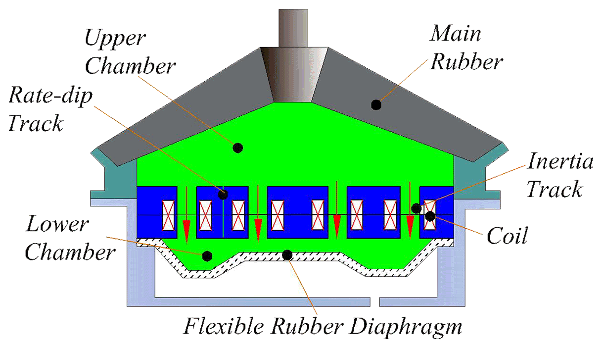
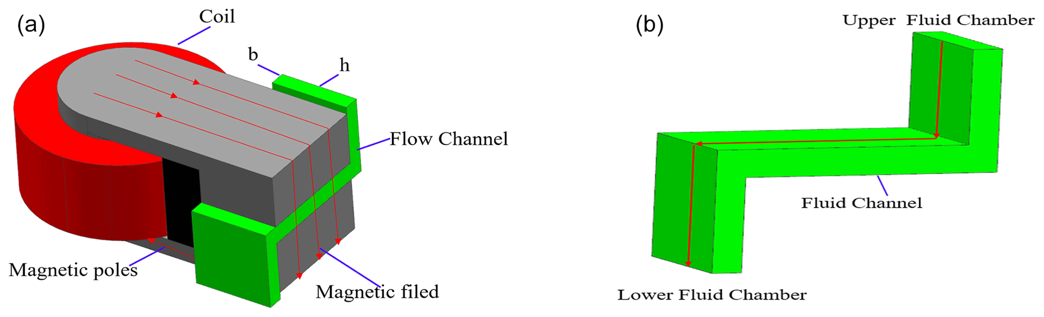
Figure 2Controlled channel and coil arrangement (a) Coil and channel assembly diagram and (b) controlled channel.

There are two conditions. (1) The engine reciprocating inertial force requires the mount to provide small stiffness and small damping, and (2) the road excitation requires the mount to provide large stiffness and damping (Yu et al., 2001b). To satisfy conditions (1) and (2), a controlled multi-channel semi-active MR fluid mount is designed to change the yield stress of the MR fluid in the damping gap by applying a current. This allows channel closing for the semi-active MR fluid mount with adjustable stiffness and damping.
The controllable multi-channel semi-active MR fluid mount is shown in Fig. 1, with its main components labeled. Figure 1 shows that the MR fluid mount consists of mainspring rubber, flexible rubber diaphragm, rate-dip channel, inertia channel, and magnetic circuit assembly. Among them, the magnetic circuit assembly consists of a coil, iron core, and spacer, as shown in Fig. 2a.
The MR fluid chamber is divided into upper and lower chambers by channels, and each chamber is filled with MR fluid. The semi-active MR fluid mount consists of four controllable channels and one rate-dip channel. In Fig. 2a the coil (in red) applied current to change the yield stress of the MR fluid in the middle part of the channel to achieve switching of the channel. The MR fluid selected was supplied by Lord (type 126CD). In Fig. 2, the copper coil is shown in red, the high-permeability material (generally pure iron for electricians) is shown in gray, and the controllable channel is shown in green. The semi-active MR fluid mount at higher current to achieve channel closing is shown in Fig. 2b in the green area of the Z-shaped channel diagram. The advantage of this design is that three different operating states can be achieved as follows. (1) When a higher current is applied to the middle part of the controllable channel, the MR fluid instantly gathers in the direction of the generated magnetic field. This increases the yield stress of the MR fluid, which prevents the flow of the fluid and indirectly controls the total cross-sectional area of the MR fluid mount controllable channel. (2) When a lower current is applied, the mount returns to the conventional inertial channel flow mode of operation, in which the mount achieves continuously adjustable damping without the channel being closed. (3) When no current is applied, the mount returns to a multi-channel passive hydraulic mount.
MR fluid type 126CD with a viscosity of 0.06 Pa s and a density of 2660 kg m−3 was selected from Lord. Using the polynomial curve fitting method, the B–H and τ–H curves of the MR fluid are shown in Fig. 3a and b.
The fitted polynomials are as follows:
The shear yield stresses fitting polynomial is given by
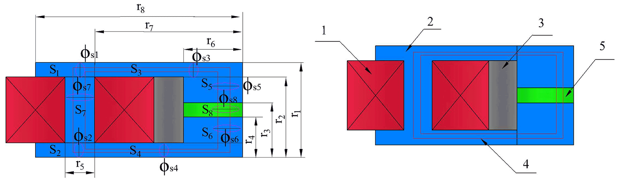
Figure 4Structure and structural parameters of the magnetic core assembly. 1 is coil, 2 is core, 3 is magnetic spacer, 4 is magnetic flux line, and 5 is the controllable channel.
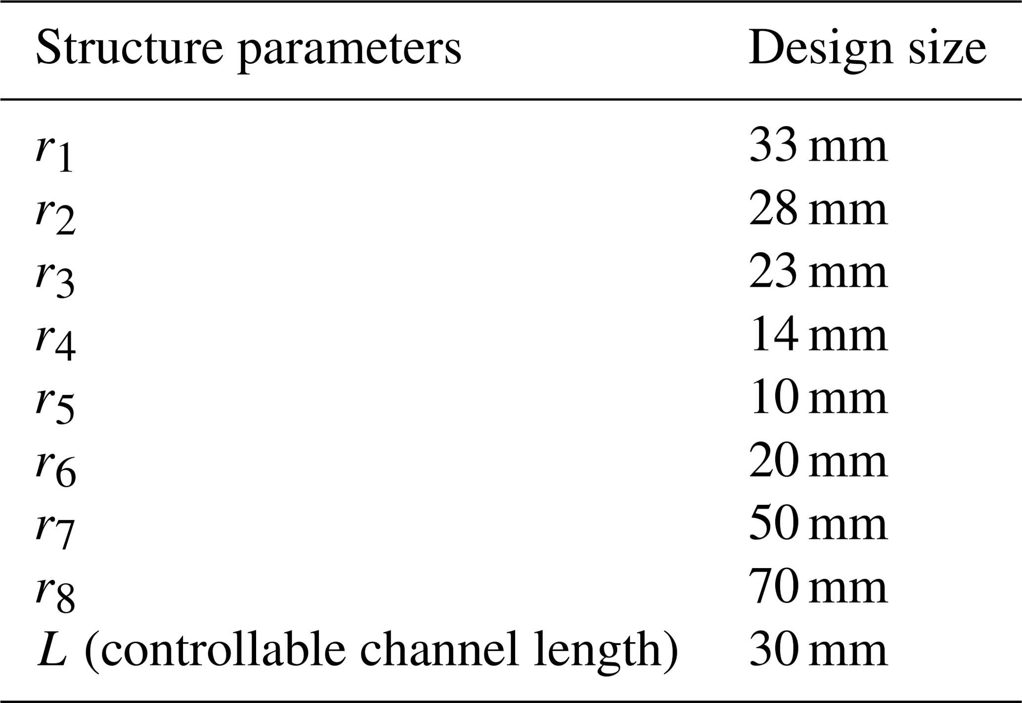

Figure 5Single controlled channel magnetic circuit characteristics: (a) magnetic flux intensity cloud and (b) magnetic flux intensity for different currents.
3.1 Magnetic circuit analysis
In order to easily calculate the MR fluid mount magnetic circuit, Fig. 2 is simplified to Fig. 4. If we assume that the flux in the magnetic circuit is uniformly distributed and that there is no magnetic leakage, then according to the law of conservation of magnetic flux, the flux density in the closed magnetic circuit is determined by the following equation.
where ϕs1, ϕs2, ϕs3, ϕs4, ϕs5, ϕs6, and ϕs7 are the core flux densities, and ϕs8 is the flux density of the MR fluid.
The magnetic circuit is analyzed using the magnetic Kirchhoff's law as follows:
where Nc is the number of turns of the excitation coil, I is the current applied to the coil, Hi is the magnetic field intensity in the ith link of the circuit, and li is the overall effective length of that link. According to Ampere's law of loops, it is known that
where Bi and Si are the magnetic flux density and cross-sectional area of the ith link, respectively.
According to the MR fluid controllable channel shown in Figs. 2 and 4, the effective length of the ith link of the circuit can be defined as
Combining Figs. 2 and 4, the equivalent cross-sectional area of each part can be calculated based on the structural dimensional parameters as follows:
According to Hu et al. (2017), Eq. (8) can be obtained:
where
where u0 is the air permeability, and ui is the relative permeability of the magnetically conductive material.
From Eqs. (5)–(9), the magnetic flux intensity in the controllable channel region is further deduced as
To ensure that the controlled channel MR fluid channel is the primary saturation state, the magnetic flux intensity of BMR should be maximized. Combining the parameters of the magnetic circuit structure in Table 1 and using Maxwell software to build the magnetic circuit structure of the controllable channel, as shown in Fig. 5, Fig 5a shows the magnetic flux intensity graph for a single controllable channel with 2.0 A applied. It can be seen that the magnetic flux core has a relatively uniform magnetic induction distribution, with an average magnetic induction of 0.93 T at the magnetorheological fluid channel. The results show that the magnetorheological fluid in the controlled channel region utilizes more magnetic energy.
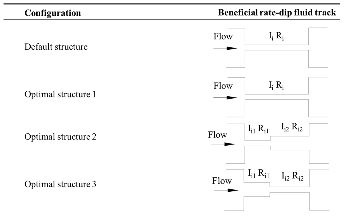
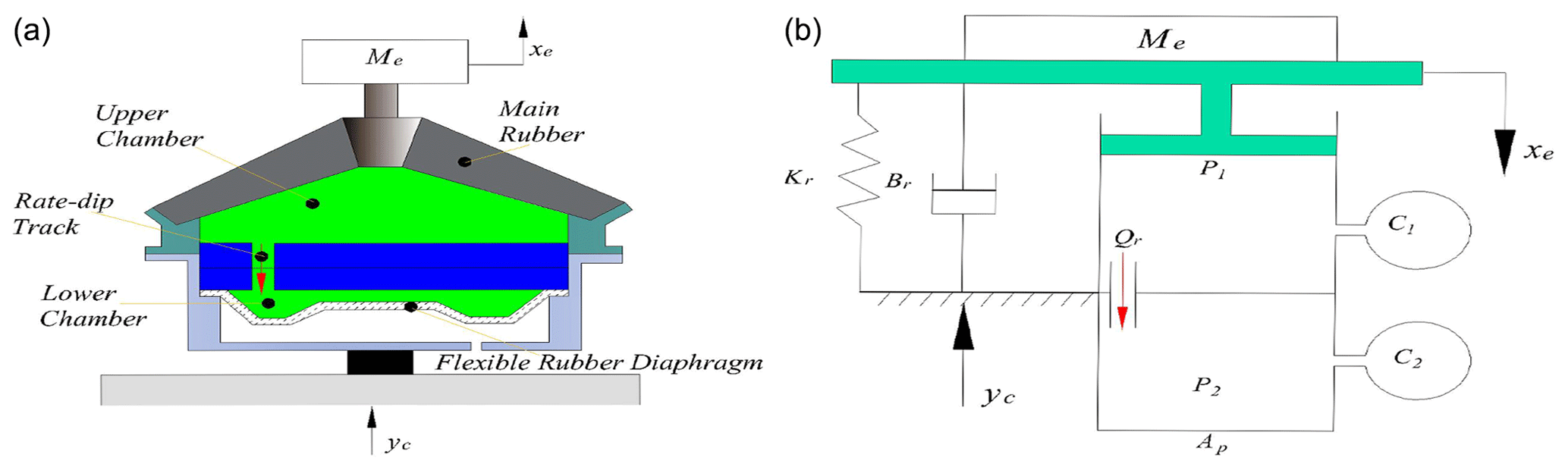
Figure 7Equivalent hydraulic mount when all controllable channels are closed: (a) schematic diagram and (b) lumped parameter model.

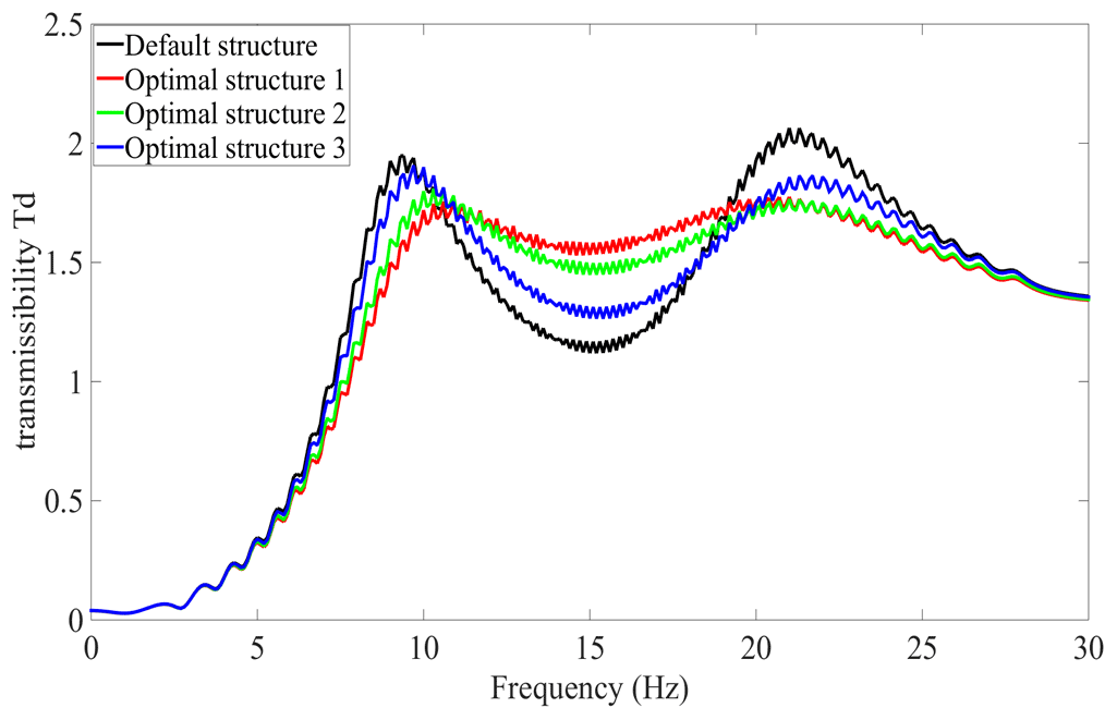
Figure 9Relative displacement transmissibility of the three optimized structures and the conventional channel structure.
3.2 Rate-dip channel optimized design
To avoid applying large currents to the four controllable channels, all four controllable channels are blocked leading to oscillatory states in the dynamic stiffness and damping of the semi-active MR fluid mount at low frequency. Adding a rate-dip channel to the controllable multi-channel semi-active MR fluid mount avoids oscillatory states of dynamic stiffness and damping. Three different rate-dip channel structures were chosen, as shown in Fig. 6. Structure 1 is a circular pipe with the same inlet and outlet, whereas structure 2 is an abruptly enlarged pipe, and structure 3 is an abruptly reduced pipe.
When all four controllable channels are closed, Fig. 1 can be simplified to the hydraulic mount shown in Fig. 7. Figure 7a shows the structure and Fig. 7b shows the lumped parameter model. In Fig. 7b, yc is the pavement excitation, and xe is the displacement of the power train; the following equations can be obtained according to the lumped parameters in Fig. 7b.
Ap is the equivalent cross-sectional area of the upper chamber, C1 and C2 are the volume flexibility of the upper and lower chambers, P1 and P2 are the pressure of the upper and lower chambers, and Qr denotes the flow rate of the fluid through the rate-dip channel. Assuming that the flow of fluid through the rate-dip channel is laminar and that the inlet losses can be neglected, the fluid inertia and fluid resistance flowing through the rate-dip channel are Ir and Rr, respectively, and the solution expression is as follows (Doebelin, 1998).
where u is the viscosity of the fluid, Lr is the length of the rate-dip channel, Dh is the hydraulic diameter of the channel, ρ is the density of the fluid, and Ar is the cross-sectional area of the channel.
In order to address the large value of engine vibration due to road excitation, all four controllable channels are closed, and the design criteria for the mount, in this case, are based on the displacement transfer rate Td of the power train relative to the vehicle frame (Foumani et al., 2004),
if we assume that the hydraulic mount is excited by xe=Xesin (2πft), amplitude Xe=5.0 mm, and frequency . The cross-sectional area of the channel of structure 1 is given as , with the channel length ; the cross-sectional area of structure 2 is given as and , with the channel length ; and the cross-sectional area of structure 3 is given as and , with channel length . Consider the local pressure loss for a sudden expansion or sudden contraction of a circular pipe. The frequency response of calculating the relative displacement transmissibility |Td| for the three structures is shown in Fig. 8. The maximum transmissibility of the relative displacements of the three different structural channels are |Td1|=2.0485, |Td2|=2.1839, and |Td3|=2.2738, respectively.
In order to achieve the minimum relative displacement transmissibility of the mount, three different rate-dip channels are used as the study objects. The design objective function is the minimum of the maximum value of the relative displacement transfer rate Td, and the design variables are the cross-sectional area and length of the channels; the multi-objective genetic algorithm is used to optimize the design of the three channel structures. After optimization, the cross-sectional area of structure 1 is and the channel length is . The cross-sectional area of structure 2 is , , and the channel lengths are and . The cross-sectional area of structure 3 is , , and channel lengths are and . The maximum transmissibility of the relative displacements of the three different structural channels are |Td1|=1.7662, |Td2|=1.79, and |Td3|=1.89. Figure 9 shows the comparison between the three optimized structures and the conventional channel structure. For this reason, optimized structure 1 is chosen as the rate-dip channel.

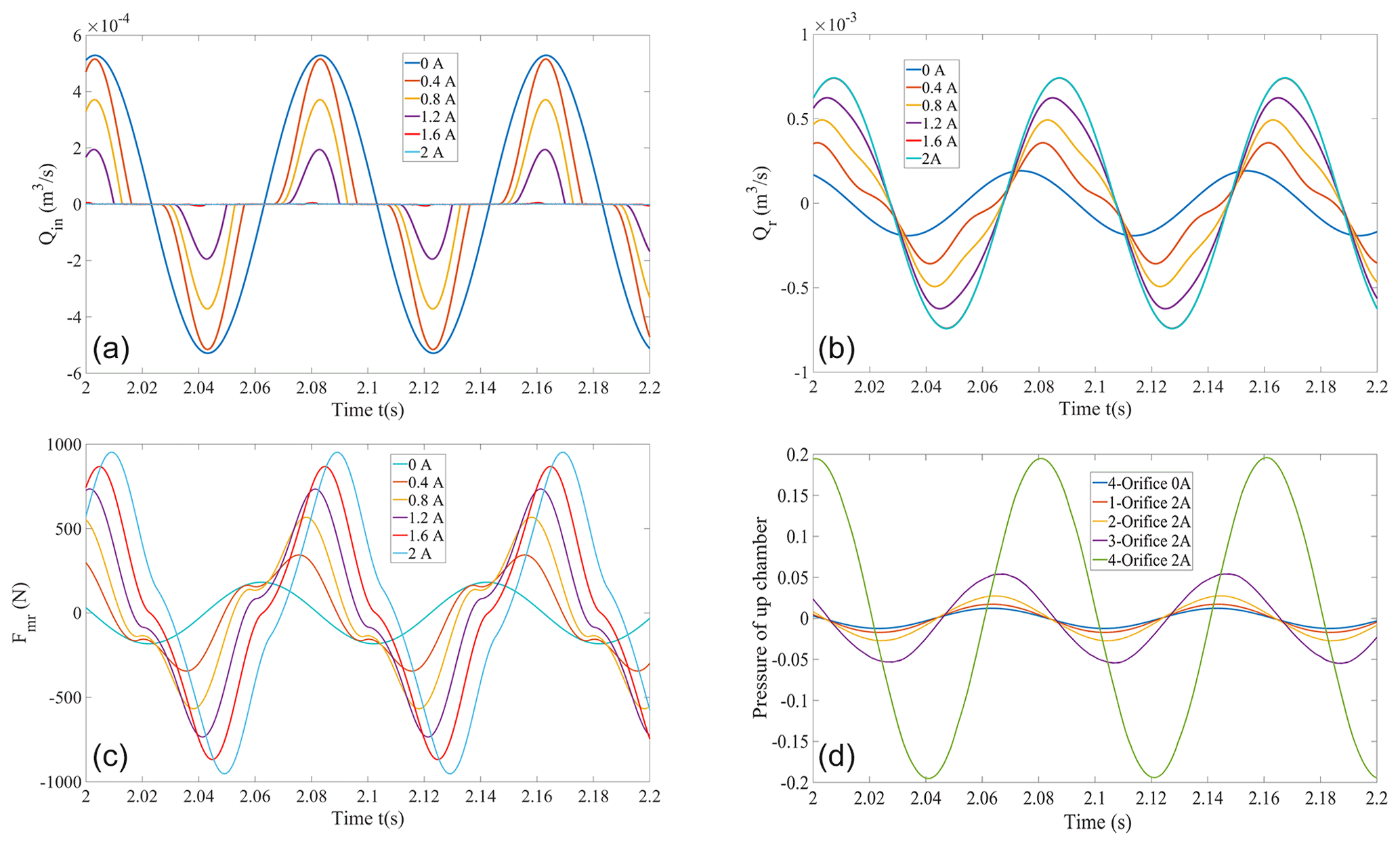
Figure 11Controlled multi-channel magnetorheological fluid mount flow, damping force, upper chamber pressure, (a) single controlled channel flow rate; (b) rate-dip flow rate; (c) single controlled channel damping force and (d) upper chamber pressure.
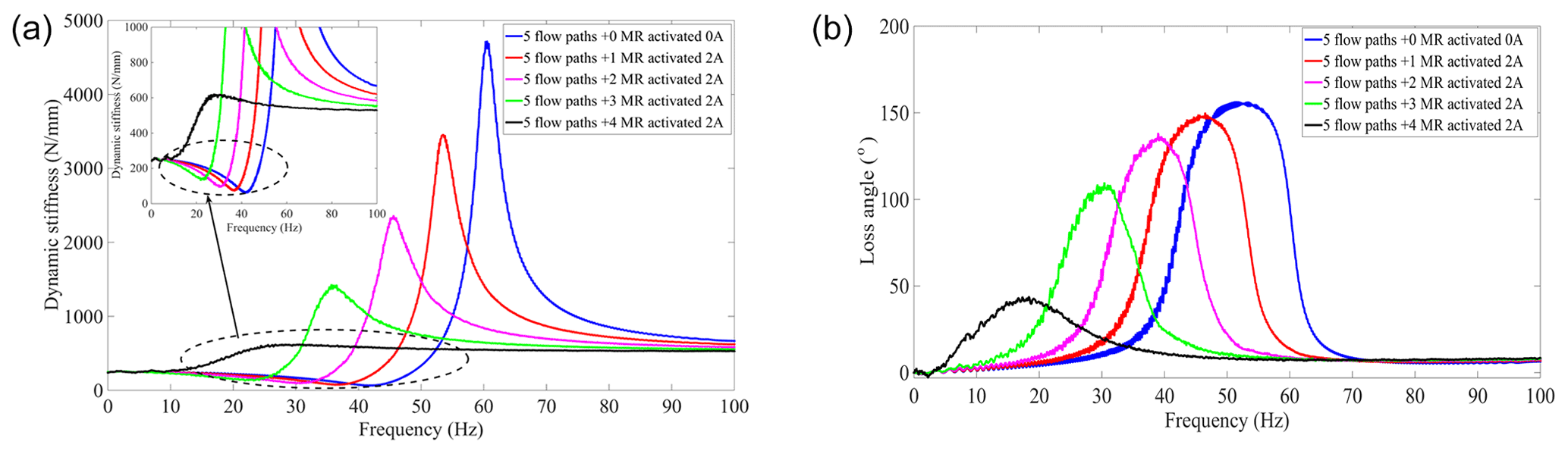
Figure 12Controllable multi-channel semi-active MR fluid mount dynamic characteristics (a) dynamic stiffness and (b) loss angle.
3.3 Damping force performance analysis of the MR mount
According to the lumped parameter model of controlled multi-fluid semi-active MR fluid mount in Fig. 10 and combined with Nguyen et al. (2013), the following equation can be found for the pressure difference between the upper and lower chambers of the mount.
where ΔPI is the pressure drop due to MR fluid flow inertia; ΔPη is the MR fluid flow pressure drop due to MR fluid viscosity; L1 is the channel length without magnetic field action shown in Fig. 2b; and ΔPMR is the pressure drop due to the MR fluid yield stress (Srinivasan et al., 2001). C is a constant in the range of 2 to 3, depending on the steady-state flow conditions; in this work, C=2 is assumed (Nguyen et al., 2013). When the MR fluid mount is excited by vibration, the main rubber spring forces the MR fluid to flow from the upper chamber to the lower chamber through the controllable and rate-dip channels, and the total flow rate of the MR fluid is given (Deng et al., 2020).
where AP is the equivalent piston area, is the average velocity of the fluid, f is the external excitation frequency, Qin is the flow rate through the nth controllable channel, and Qr is the flow rate through the rate-dip channel.
The pressure drop of the ith controllable channel is
So, the damping force of the ith controllable channel is
where Fηin is the ith controllable channel viscous damping force, and Fτin is the controllable damping force of the MR mount.
We performed numerical simulation of the MR fluid mount subjected to an external excitation frequency of 12.5 Hz and excitation amplitude of 3 mm. Analysis of the flow rate variation, damping force, rate-dip channel flow rate, and upper chamber pressure variation for a single controllable channel is shown in Fig. 11.
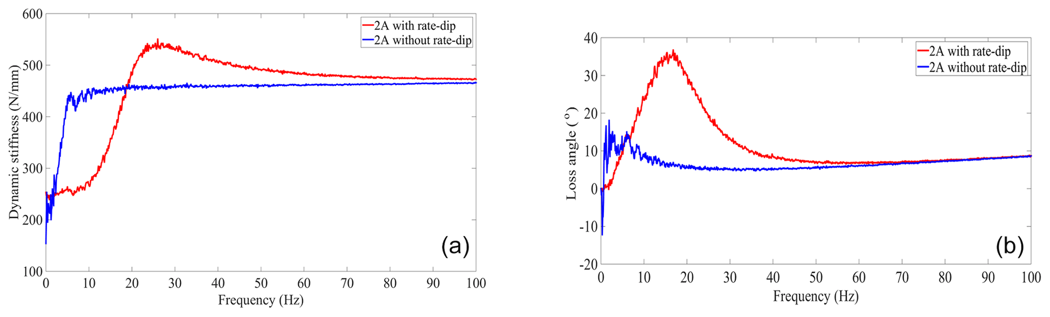
Figure 13Effect of the presence or absence of the rate-dip channel on the dynamic characteristics of MR fluid mount (a) dynamic stiffness and (b) loss angle.
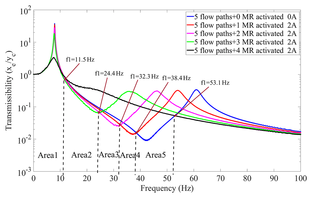
Figure 14Transmissibility of MR fluid semi-active mount switching for different controllable channels.
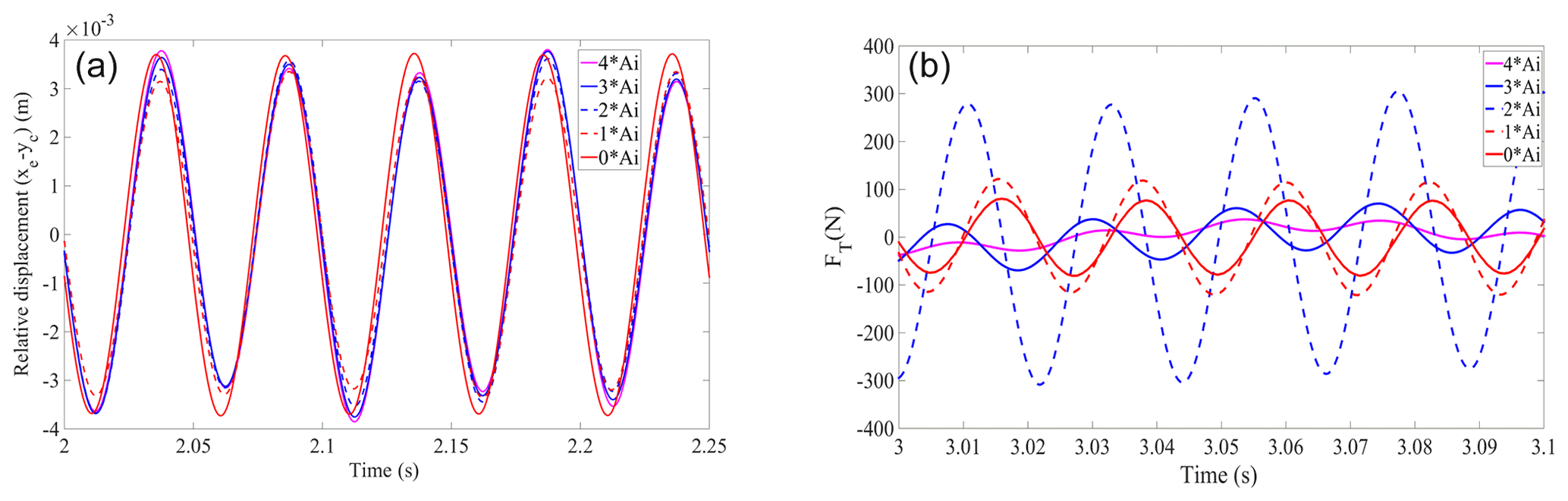
Figure 15Effect of different excitation sources on the mount: (a) relative displacement of the engine and the frame and (b) transfer force.
4.1 Dynamic characteristics
For the frequency domain analysis, the parameters for evaluating the dynamic characteristics of the MR fluid mount are dynamic stiffness and loss angle. Dynamic stiffness is the ratio of vibration response force amplitude to vibration displacement amplitude at the external excitation frequency. The loss angle responds to the angle at which the displacement lags behind the force and characterizes the magnitude of the vibration isolator damping force. The complex stiffness of the semi-active mount of controlled multi-fluid magnetorheological fluid is defined as
where xe is the engine displacement excitation, FT is the transfer force transmitted to the vehicle frame, K′ is the storage stiffness of the mount, K′′ is the loss stiffness of the mount, and the mode and loss angle of the dynamic stiffness of the mount are given below (Shangguan, 2009):
According to Figs. 1 and 10, the mathematical equations of the controllable multi-channel semi-active MR fluid mount single-degree-of-freedom system can be derived as
According to the above equations, the dynamic stiffness and loss angle of the controllable multi-channel semi-active MR fluid mount can be obtained as shown in Fig. 12.
In Fig. 12, the solid black line represents the four controllable channels where a 2 A current can be applied in the MR fluid mount in the low-frequency range to achieve large stiffness and large damping. When three channels are used with 2 A current, the dynamic stiffness and loss angle of the MR fluid mount are shown as the solid green lines in Fig. 12a and b, where the mount reaches its minimum stiffness at 0–22 Hz, and the peak loss angle moves to about 30 Hz. When the MR fluid conducts the 2 A current in each of the two channels (the solid red line in Fig. 12), the minimum dynamic stiffness value of the mount broadens to 30 Hz at the peak frequency, while the peak loss angle appears at 40 Hz. For the MR fluid mount, when each of the two channels applies a current of 2 A (the solid red line in Fig. 12), the peak frequency of the minimum dynamic stiffness value of the mounts broadens to 30 Hz, while the peak loss angle appears at 40 Hz. When a controllable channel with 2 A current is used (the solid red line in Fig. 11), the minimum dynamic stiffness of the MR fluid mount appears at 40 Hz, and the loss angle peaks at 43 Hz. When all four controllable channels are not conducting any current, the minimum dynamic stiffness of the MR fluid mount is at 42 Hz, and the peak loss angle is at 52 Hz (the solid blue line in Fig. 12). Therefore, a 2 A current is applied to different controllable channels to realize the switching closed of the channels, and the adjustable dynamic stiffness and damping of the semi-active MR fluid mount can realize the mount's wide-frequency vibration isolation.
Based on the optimal rate-dip channel structure proposed in Sect. 2.2, the effect of the presence and absence of rate-dip channels on the dynamic characteristics of the MR fluid mount is simulated numerically. The chaotic state of dynamic stiffness and loss angle of the mount without rate-dip channel is compared to with rate-dip channel in the structure of controlled multi-fluid semi-active MR fluid mount (black oval region in the Fig. 13). In Fig. 13b there is even a negative loss angle. Therefore, the designed controllable multi-channel semi-active MR fluid mount needs to consider the effect of the rate dip on its dynamic characteristic.
Numerical simulation of the variation of displacement transmissibility for different channels with 2 A current is shown in Fig. 14.
According to Fig. 14, the graphs and controllable areas of different frequency bands with different displacement transmissibility are divided.
where Ac in Eq. (28) is the total cross-sectional area of the controllable channel, and Ai is the cross-sectional area of the single controllable channel.
Between 0 and ∼11.5 Hz, all four controllable channels applied 2 A current (the solid black line in Fig. 1), and a better isolation effect can be achieved in area 1. For the controllable multi-channel semi-active MR fluid mount, three controlled channels applied 2 A current (the solid green line in Fig. 14) in area 2 between 11.5 and ∼24.4 Hz and can provide a better vibration isolation effect. For the controllable multi-channel semi-active MR fluid mount, two controlled channels applied 2 A current (the solid magenta line in Fig. 14) in area 3 between 24.4 and ∼32.3 Hz and can provide a better vibration isolation effect. For the controllable multi-channel semi-active MR fluid mount, one controlled channel applied 2 A current (the solid red line in Fig. 14) in area 4 between 32.3 and ∼38.4 Hz and can provide a better vibration isolation effect. For the controllable multi-fluid semi-active MR fluid mount with four channels without a current (solid blue line in Fig. 14), the mount with the total controllable cross-sectional area of Ac=4Ai can achieve good vibration isolation between 38.4 and ∼53.1 Hz in area 5. According to the above judgment conditions, the external excitation is known to apply current to the different controllable channels to make the channel switch closed and achieve the best vibration isolation effect of the mount system.
The controllable multi-channel semi-active MR fluid mount is considered to be subjected to a road excitation with a frequency of 20 Hz and an amplitude of 3 mm and an engine excitation with a frequency of 45 Hz and an amplitude of 1000 N. To verify the effect of different channels switch closing on the relative displacement of the engine to the vehicle frame and the transfer force between the engine and the vehicle frame, numerical calculation of the variation of the relative displacement transmissibility and force transmissibility between the engine and the vehicle frame for different controlled channel switch closing is shown in Fig. 15. Figure 15a shows that when the mount is subjected to a frequency of 20 Hz and an amplitude of 3 mm, the controllable area is Ac=Ai, and the displacement of the engine relative to the vehicle frame is minimal; in agreement with Fig. 14 area 2, the transmissibility is minimal. In Fig. 15b, when the mount is subjected to 45 Hz, the force amplitude is 1000 N when the controllable area Ac=4Ai meets the minimum transmissibility of area 5 in Fig. 14.

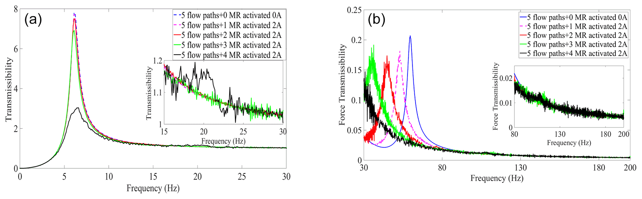
Figure 17Effect of mount isolation of the vehicle model: (a) relative displacement transmissibility and (b) force transmissibility.
4.2 MR mount in vehicle model
Automotive designers can better predict the mount vibration isolation performance by analyzing the vehicle model (Ladipo et al., 2016). The vehicle model of the controllable multi-channel semi-active MR fluid mount is shown in Fig. 16. Equations (29) and (30) for the vehicle model of controlled multi-channel semi-active MR fluid mount are given.
where Ku and Bu are the stiffness and damping of the mount, respectively, and Mc is of the vehicle mass.
The vehicle model is divided into low-frequency (0–20 Hz) and high-frequency (20–200 Hz). The low-frequency engine displacement transmissibility to the vehicle frame is minimized, and the high-frequency engine excitation force is minimized to the vehicle frame force as the evaluation index. Combining Eqs. (30) and (31) yields the relative displacement transmissibility Td and the force transmissibility TF, where TF is given in Eq. (31).
When the system is subjected to a large-amplitude excitation of the road surface with a frequency of 0–30 Hz, the engine displacement transmissibility vs. the number of controlled channel openings is shown in Fig. 17a. Figure 17b curve of the engine transfer to vehicle frame force transmissibility with the number of controlled channel openings. In Fig. 17a, the relative displacement transmissibility decreases with the increase in the number of controllable channels with 2 A current applied. This is due to the increase in mount damping due to the number of applied currents in the controllable channel, which makes the resonance peak lower. However, when 2 A current is applied to all four controllable channels, the stiffness of the mount increases, which leads to an increase in the resonance peak, and the black solid line in Fig. 17a shows the resonance peak at around 20 Hz. In Fig. 17b the solid blue line shows the minimum force transmissibility available at 37 to 51 Hz and 93 to 200 Hz for all four controllable channels with no current applied. The magenta dotted line shows one of the four controllable channels applying 2 A current at 32 to 37 Hz to achieve the minimum force transmissibility. The red solid line shows the minimum force transmissibility at 23 to 32 Hz when a 2 A current is applied to both controllable channels. The green solid line shows the minimum force transmissibility at 20 to 23 Hz when 2 A current is applied to all three of the controllable channels. The solid black line shows that the four controllable channels applied 2 A current between 51 and ∼93 Hz where the controllable multi-channel semi-active MR fluid mount can achieve the minimum transfer force.
So, in practical use, once the type of vehicle is selected, the excitation frequency range of the engine is known. When the vehicle is driven on rough roads, a 2 A current is applied to all four controllable channels of the semi-active MR fluid mount to minimize the relative displacement of the engine and the vehicle frame. When the vehicle is driving on a better road, the number of controllable channels can be switched on and off from 1–4 according to the specific engine speed and according to different engine speeds. For example, no current is applied to any of the four controllable channels of the semi-active MR fluid mount when the vehicle is on the highway. When the vehicle is at a stationary state, the following happens: (1) when the engine is idling without load, the three controllable channels of the semi-active MR fluid mount apply 2 A current, and (2) when the engine is idling with load, the four controllable channels of the semi-active MR fluid mount do not apply current.
Semi-active MR fluid mount with four controllable channels and one rate-dip channel, characterized by applying a current to the four controllable channels, making the controllable channel switching. Controlled channel switch close makes the total cross-sectional area of the MR fluid mount channel change, thus realizing adjustable mount dynamic stiffness and damping. rate-dip channels are unaffected by magnetic fields and are always flowing. As a result, the following conclusions can be drawn. (1) The designed magnetic circuit structure can meet the channel switching requirements, different channel applied currents, and can realize the design of controllable multi-channel MR fluid mount to achieve wide-frequency vibration isolation. (2) The rate-dip channel improves semi-active mount low-frequency isolation performance when all four controllable channels are closed. Simultaneously, currents are applied to different controllable channels to derive the optimal range of vibration isolation frequencies. (3) For the vehicle model numerical simulation of the controllable channel, the low-frequency range is evaluated by the relative displacement transmissibility of the engine from the frame and the reciprocating unbalanced force of the engine to the frame at high frequency. Low and high frequencies can reduce the relative displacement transmissibility and force transmissibility when the controllable channel switch closes different channels.
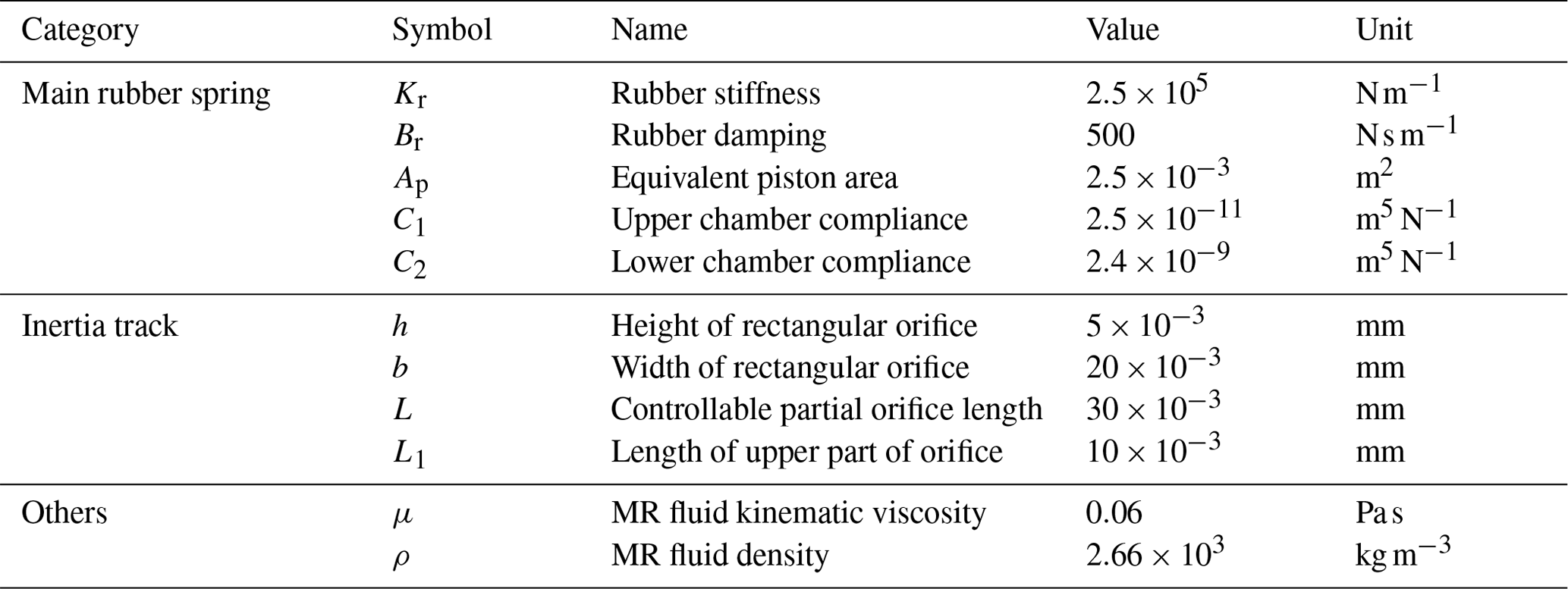
Table A1Controlled multi-channel semi-active magnetorheological fluid mount parameters.
All data included in this study are available upon request from the corresponding author.
ZL is responsible for the methodology proposal and the writing of the draft paper. MW contributed to the grammar check.
The authors declare that they have no conflict of interest.
Publisher's note: Copernicus Publications remains neutral with regard to jurisdictional claims in published maps and institutional affiliations.
This research has been supported by the Quanzhou City Science&Technology Program of China (grant no. 2018Z016).
This paper was edited by Zi Bin and reviewed by three anonymous referees.
Chen, P., Bai, X.-X., Qian, L. J., and Choi, S. B.: A magneto-rheological fluid mount featuring squeeze mode: analysis and testing, Smart Mater. Struct., 25, 055002, https://doi.org/10.1088/0964-1726/25/5/055002, 2016.
Christopherson, J., Mahinfalah, M., and Jazar, R. N.: Suspended Decoupler: A New Design of Hydraulic Engine Mount, ADV, Acous. Vib., 2012, 1–11, https://doi.org/10.1155/2012/826497, 2012.
Deng, Z., Yang, Q., and Yang, X.: Optimal design and experimental evaluation of magneto-rheological mount applied to start/stop mode of vehicle powertrain, J. Intel. Mat. Syst. Str., 1–12, https://doi.org/10.1177/1045389x20910271, 2020.
Doebelin, E. O.: System dynamics: Modeling, analysis, simulation, design, Marcel dekker, Inc, Marcel Dekker, New York, 1998.
Fan, R.: Experiment study of nonlinear dynamic characteristics for three types of hydraulic engine mount and parameters identification method, J. Mech. Eng., 42 174–181, https://doi.org/10.3901/JME.2006.05.174, 2006.
Fan, R., Fei, Z., Zhou, B., Gong, H., and Song, P.: Two-step dynamics of a semiactive hydraulic engine mount with four-chamber and three-fluid-channel, J. Sound Vib., 480, 115403, https://doi.org/10.1016/j.jsv.2020.115403, 2020.
Foumani, M. S., Khajepour, A., and Durali, M.: A New High-Performance Adaptive Engine Mount, J. Vib. Control, 10, 39–54, https://doi.org/10.1177/107754604773684894, 2004.
Hausberg, F., Scheiblegger, C., Pfeffer, P., Plöchl, M., Hecker, S., and Rupp, M.: Experimental and analytical study of secondary path variations in active engine mounts, J. Sound Vib., 340, 22–38, https://doi.org/10.1016/j.jsv.2014.11.024, 2015.
Hu, G., Liao, M., and Li, W.: Analysis of a compact annular-radial-orifice flow magnetorheological valve and evaluation of its performance, J. Intel. Mat. Syst. Str., 28, 1322–1333, https://doi.org/10.1177/1045389x16672561, 2017.
Imaduddin, F., Mazlan, S. A., and Zamzuri, H.: A design and modelling review of rotary magnetorheological damper, Mater. Design, 51, 575–591, https://doi.org/10.1016/j.matdes.2013.04.042, 2013.
John, R. and Kumar, S.: Development and testing of a closed loop feedback controlled magnetorheological fluid anti-vibration mount for onboard naval applications, Defence Sci. J., 66, 374–380, https://doi.org/10.14429/dsj.66.10211, 2016.
Ladipo, I. L., Fadly, J. D., and Faris, W. F.: Characterization of Magnetorheological Elastomer (MRE) Engine Mounts, Mater. Today-Proc., 3, 411–418, https://doi.org/10.1016/j.matpr.2016.01.029, 2016.
Lee, K. H., Choi, Y. T., and Hong, S. P.: Performance Design of Hydraulic Mount for Low Frequency Engine Vibration and Noise Control, SAE Tec., https://doi.org/10.4271/941777, 1994.
Li, Y., Jiang, J. Z., and Neild, S. A.: Optimal fluid passageway design methodology for hydraulic engine mounts considering both low and high frequency performances, J. Vib. Control, 25, 2749–2757, https://doi.org/10.1177/1077546319870036, 2019.
Mansour, H., Arzanpour, S., Golnaraghi, M. F., and Parameswaran, A. M.: Semi-active engine mount design using auxiliary magneto-rheological fluid compliance chamber, Vehicle Syst. Dyn., 49, 449–462, https://doi.org/10.1080/00423111003596750, 2011.
Nguyen, Q. H., Choi, S. B., Lee, Y. S., and Han, M. S.: Optimal design of high damping force engine mount featuring MR valve structure with both annular and radial flow paths, Smart Mater. Struct., 22, 115024, https://doi.org/10.1088/0964-1726/22/11/115024, 2013.
Römling, S., Vollmann, S., and Kolkhorst, T.: Active Engine Mount System In The New Audi S8, MTZ Worldwide, 74, 34–38, https://doi.org/10.1007/s38313-013-0006-7, 2013.
Shah, K. and Choi, S. B.: The influence of particle size on the rheological properties of plate-like iron particle based magnetorheological fluids, Smart Mater. Struct., 24, 15004–15011, https://doi.org/10.1088/0964-1726/24/1/015004, 2015.
Shangguan, W. B.: Engine mounts and powertrain mounting systems: a review, Int. J. Vehicle Des., 49, 237, https://doi.org/10.1504/ijvd.2009.024956, 2009.
Srinivasan, A. V., McFarland, D. M., Spillman, Jr., and W. B.: Smart Structures, Analysis and Design, Am. J. Phys., 69, 1212–1212, https://doi.org/10.1119/1.1407258, 2001.
Tikani, R., Vahdati, N., and Ziaei-Rad, S.: Two-mode operation engine mount design for automotive applications, Shock Vib., 19, 1267–1280, https://doi.org/10.3233/SAV-2012-0669,2010.
Truong, T. Q. and Ahn, K. K.: A new type of semi-active hydraulic engine mount using controllable area of inertia track, J. Sound Vib., 329, 247–260, https://doi.org/10.1016/j.jsv.2009.09.015, 2010.
Wang, M., Yao, G., Zhao, J., and Qin, M.: A novel design of semi-active hydraulic mount with wide-band tunable notch frequency, J. Sound Vib., 333, 2196–2211, https://doi.org/10.1016/j.jsv.2013.12.004, 2014.
Yu, Y., Naganathan, N. G., and Dukkipati, R. V.: A literature review of automotive vehicle engine mounting systems, Mech. Mach. Theory, 36, 123–142, https://doi.org/10.1016/s0094-114x(00)00023-9, 2001a.
Yu, Y., Peelamedu, S. M., Naganathan, N. G., and Dukkipati, R. V.: Automotive Vehicle Engine Mounting Systems: A Survey, J. Dyn. Syst.-T. ASME, 123, 186–194, https://doi.org/10.1115/1.1369361, 2001b.
Zhu, X., Jing, X., and Cheng, L.: Optimal design of control valves in magnetorheological fluid dampers using a nondimensional analytical method, J. Intel. Mat. Syst. Str., 24, 108–129, https://doi.org/10.1177/1045389x12461721, 2012.
- Abstract
- Introduction
- Controlled multi-channel MR fluid mount
- Analysis of the MR mount model
- Analysis of dynamic characteristics of semi-active mounts of the multi-fluid MR mount
- Conclusions
- Appendix A
- Data availability
- Author contributions
- Competing interests
- Disclaimer
- Financial support
- Review statement
- References