the Creative Commons Attribution 4.0 License.
the Creative Commons Attribution 4.0 License.
 | 21 Jul 2021
Crushing mechanism of a mobile pellet harvester
Yanyan Ge
Zichao Su
Maohua Xiao
Min Kang
Ruyi Wang
Qin Zeng
The treatment and utilization of straw is a considerably complex type of problem in agricultural production. A mobile pellet harvester integrates the mechanisms of picking, drying, crushing, and pelletizing, thereby solving the problem caused by the traditional method and reducing human effort and material resources. The crushing mechanism of a mobile pellet harvester was designed and studied, and the shape of the hammer slice was innovatively proposed, thereby substantially improving the working efficiency during the crushing process. Ansys finite element analysis software was used to perform static and dynamic analyses of the key components of the crushing mechanism (i.e., hammer slices, hammer framework, and crushing spindle). These components have sufficient rigidity, strength, and good dynamic balance to meet the working requirements of the straw pulverizer.
- Article
(12529 KB) - Full-text XML
- BibTeX
- EndNote


Straw is the largest crop by-product produced in agricultural production. However, only a small amount of straw is used for livestock feeding, and most of the remaining straw is incinerated in the field (Hao et al., 2018). With the progress of agricultural production, the amount of straw has also increased considerably, and long-term, large-scale burning of straw continuously worsens our environment (Sun et al., 2020). Therefore, studies have proposed that the comprehensive development and utilization of crop straw should be improved to turn waste into treasure (Shi et al., 2018).
At present, straw has various utilization methods, such as returning land, carbonizing, generating electricity, making fodder, straw-charcoal-based fertilizer, and straw biogas (Xiong et al., 2010). With the increasing demand for straw, how to collect the scattered straw in the field immediately and effectively has become an urgent problem to be solved. The efficient utilization of straw is needed by changing the traditional straw collection method and using modern mechanized technology to collect straw. The main reasons for the low technology includes straw collection and treatment. The technology level is low, and the commonly used collection processing equipment is mainly small equipment. A structural contradiction is prominent, the existing small machinery have low working efficiency, and large machinery compatible with the use of large-scale industries is lacking (Jian and Liu, 2013). The application range of mechanization is narrow, only a small part of the straw treatment process has been used by modern machinery, and there is no equipment to solve the continuous operation (Miao et al., 2011).
A mobile pellet harvester is straw collection equipment integrating picking, collecting, crushing, drying, and pelletizing (Tumuluru, 2014). This machine can collect and process straw in the field and directly process it into straw particles instead of the traditional tedious separation process (Zhang et al., 2011). The operation substantially improves the working efficiency of straw collection, reduces human effort and material resources, and also improves the comprehensive utilization rate of straw (Zong et al., 2016).
The crushing part is designed to be installed on the mobile pellet harvester after the pick-up and collection device and before the granulation device (Wang et al., 2009). As shown in Fig. 1, after the straw is collected by the picking device, it is sent to the conveyor belt 1 (1), and the straw transmitted on the conveyor belt 1 (1) is compressed by the upper feed roll (2) and the lower feed roll (4) through the feeding device (3). The straw is initially cut under the action of the moving blade (6) and fixed blade (7) driven by the cylinder (5). Thereafter, the straw fragments, crushed for the first time, fall into the hopper (8) and are driven into the crushing chamber (14) by the conveyor belt 2 (2) for secondary crushing. After the material enters the crushing chamber (14), it is hit by the hammer slices (13) that move in a circular motion with the rotor movement. The hit material further flies to the screen plate of the machine body and collides (Saez-Trumper, 2019). In the crushing chamber (14), the material interacts with the hammer slices (13) and screen plate. The material conforming to the crushing standard falls into the drying chamber (17) through the screen (12), is dried and cooled by the drying device, and is eventually blown out from the discharging tube (18) by a blower (10).
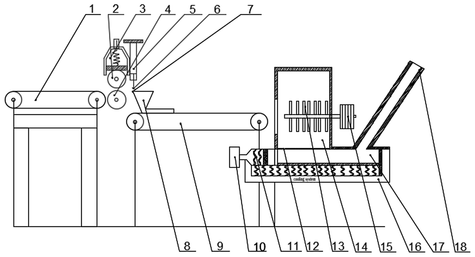
Figure 1Overall structure diagram of the crushing system. (1) Conveyer belt 1. (2) Upper feed roll. (3) Feeding device. (4) Lower feed roll. (5) Cylinder. (6) Moving blade. (7) Fixed blade. (8) Hopper. (9) Conveyer belt 2. (10) Blower. (11) Heater coil. (12) Screen. (13) Hammer slice. (14) Crushing chamber. (15) Motor. (16) Condensation system. (17) Drying chamber. (18) Discharging tube.
The hammer mill is generally composed of a feed inlet, feed outlet, body, rotor system, truss plate, screen, and transmission system (Zhang et al., 2007).
The rotor system is the most important working component of the crushing mechanism, which mainly consists of hammer slices, a rotating spindle, pins, and hammer frameworks (Mani et al., 2006). The entire rotor system is mounted on the frame by bearings, and a section of the rotating spindle is connected to the motor, thereby carrying out the main movement of the crushing mechanism (Kaliyan and Morey, 2009).
3.1 Design of the hammer slices
The structure of the hammer slice has various forms, mainly divided into a slat-shaped rectangular hammer slice and step-shaped hammer slice and a few of the considerably complex working environments using the ring hammer slice (Hill et al., 2008). The rectangular hammer slice has a simple shape, is easy to manufacture, and has good generality. It has two pin holes and can be used alternately at the four corners, thereby increasing the service life and economic performance of the hammer slice. Moreover, the rectangular hammer slices with welded edges improve the service life by welding the four corners with wear-resistant metal, although the cost is considerably high. The step-shaped hammer slices (e.g., trapezoid, diamond, and angle) have a high crushing efficiency compared with the rectangular hammer slice, but they have poor wear resistance (Wang, 2018). The structure of the ring hammer is complex and the cost is high, which is suitable for some special working environments. By considering the actual situation of this crushing device, the straw has been crushed once by the guillotine before entering the crushing chamber. Thus, its crushing efficiency has been substantially improved during the second crushing, resulting in the service life of the hammer slice becoming the main consideration. Therefore, a rectangular hammer is initially selected. Experiments have shown that the length of the hammer slice is crucial. If the hammer slice is considerably long and thick, then the metal consumption increases and the output per degree is reduced, which is not conducive to production efficiency. If the hammer slice is markedly short and thin, then the impact and wear resistance will be reduced, thereby diminishing service life.
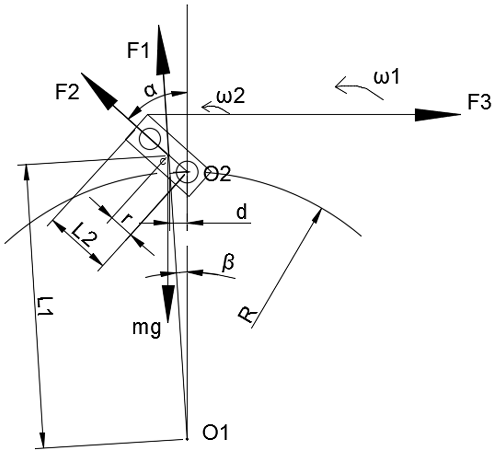
Figure 2Motion diagram of the hammer slice. O1 – spindle axis; O2 – pin axis; R – the spin radius of the pin around the spindle; C – hammer slice centroid.
The structure of a hammer mill rotor is characterized by the hammer slices being hinged with the pin, and each hammer slice can be regarded as a single pendulum motion with the pin as the origin, with the circular motion of each hammer slice around the spindle with the movement of the rotor.
As shown in Fig. 2, O1 is the spindle axis, O2 is the pin axis, C is the hammer slice centroid, F1 is the centrifugal force generated by the rotation of the hammer slice around the spindle, F2 is the centrifugal force generated by the rotation of the hammer slice around the pin, f is friction between the hammer slice and inner surface of the pin hole, N is the pressure between the hammer slice and the inner surface of the pin hole, and mg is the gravity. Forces subjected to the hammer sheet include gravity (mg) acting on the centroid, centrifugal force F1, F2, motion resistance F3 during motion, and force N, f, which act on the hinge of the hammer slice and pin. The motion consists of the rotation of the hammer slice around the axis of the spindle ω1 and the simple pendulum motion of the hammer slice around the axis of pin ω2. When the hammer mill works, the hammer slice moves with the spindle at high speed under the connection of the pin. Moreover, there is a deflection angle β when the hammer slice moves, and the positive pressure between the hammer slice and pin is produced during movement. Thus, friction force is produced on the contact surface.
Accordingly, the physical analysis of the hammer slice was conducted on the basis of the preceding discussion.
Take the moment on the point O2 as follows:
Given that the hammer slice swings slightly around the pin axis, sin α≈α and cos α≈1.
Moreover, in the following:
Thereafter, in the following:
Take the moment on the point O1 as follows:
The resultant force is as follows.
Given that the hammer slice swings slightly around the pin axis, sin α≈α and cos α≈1.
In addition, in the following:
Thus, in the following:
According to experience, the excessive deflection angle of the hammer slice will reduce the crushing efficiency, increase the dynamic imbalance of the rotor, cause the device to vibrate excessively, generate large noise, and reduce service life (Stelte et al., 2011).
Equation (9) shows that the geometric parameters of the hammer slice have a certain influence on the crushing efficiency. The centroid is far from the pin axis, and the deflection angle is small, which is good for crushing. The hammer slice area A is large, and the deflection angle is small, which is good for crushing. The spindle radius R is small, and the deflection angle is small, which is good for crushing.
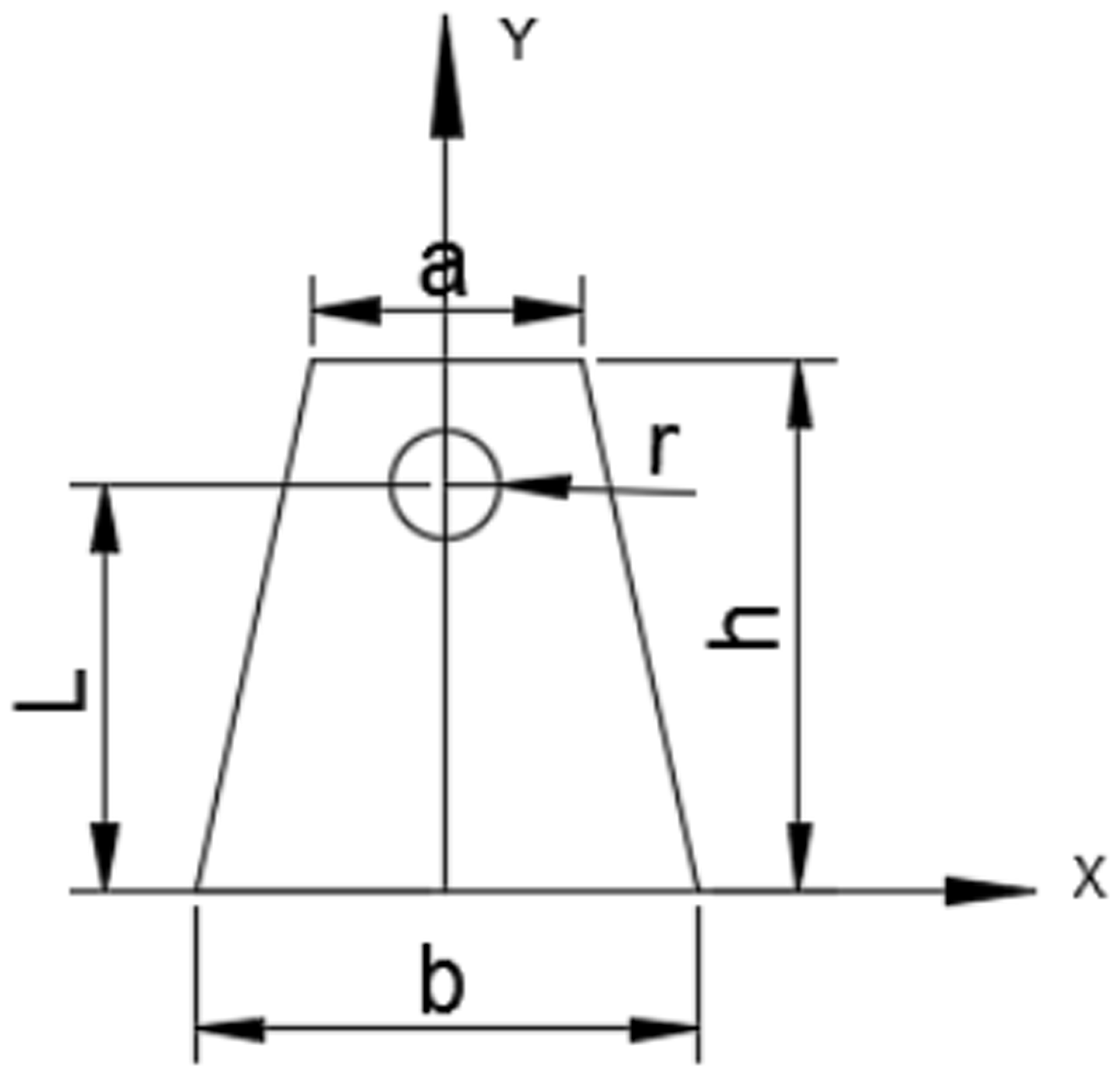
Given the preceding analysis, the shape of the hammer slice is further designed to be trapezoidal, as shown in Fig. 3, thereby enabling the centroid to be close to the blade tip, and the centroid of the hammer is calculated using the negative area method (Zhou et al., 2011). Let the area of the round hole be S1 and the area of trapezoid be S2.
Research has shown that the thickness of the hammer slice used in the Chinese market is generally 4–6 mm. Although the thickness of a thin hammer slice is sharp, the grinding effect is better and grinding efficiency is high. However, the thin hammer slice will reduce service life, thereby increasing waste in the production process. Given that there is preliminary crushing before the straw enters the crushing chamber, the thickness of the hammer is designed to be 5 mm.
We then determine the following: a=40.00 mm, b=80.00 mm, h=150.00 mm, L=120.00 mm, and r=10.00 mm. The centroid is as follows: XC=0 and YC=66.60 mm.
3.2 Design of the hammer framework
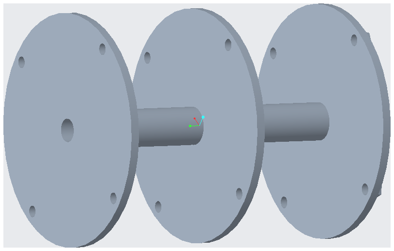
The material of the hammer framework is Q235 steel. The three hammer frameworks are placed in parallel on the same shaft, as shown in Fig. 4, and five groups of hammer slices are placed between each hammer framework at a distance of 240 mm. Each hammer framework has a diameter of 400 mm and thickness of 15 mm. In addition, each hammer framework is evenly opened with four pin holes, with a diameter of 20 mm, located on a circle with a shaft having a diameter of 360 mm as the center.
3.3 Design of the crushing spindle
The crushing spindle of a hammer mill is a transmission shaft, which is directly connected to the output end of the motor, and the other end is fixed. The spindle mainly transmits torque and bears torsional moment. Given the preceding working conditions, the spindle of 40 Cr (quenching and tempering) is selected, which can bear large loads, hardness is 241–286 HBS, and allowable stress is [σ]=735 MPa. Given that the crushing spindle is the transmission shaft, the diameter of the spindle is calculated according to the torsional strength condition, and the calculation Eq. (11) of the spindle diameter is as follows:
where d is the spindle diameter, in millimeters, A0 is the material coefficient giving 150, P is the power delivered by the spindle in kilowatts, and N is the speed of the spindle in revolutions per minute (r/min).
Place the power P=5.50 KW and spindle speed n=2000 r/min into the Eq. (11) and find d=21.02 mm. The connection between the spindle and rotor system is crucial. Given the weakening effect of the key groove on spindle strength, the spindle diameter is increased by 7 %, d=22.49 mm, and the standard value of the diameter is 40 mm.
4.1 Static analysis of the hammer slices
4.1.1 Mesh generation of the 3D models
The model is divided by the meshing tool in Ansys, the edge length is set to 2, and the mesh in the local area is refined. After the division is completed, the number of division units is found to be 2578, and the number of nodes is 2732.
4.1.2 Applying constraints and loads
The hammer slice was connected to the hammer framework through the pin and moves along with the crushing spindle. Hence, all 6 degrees of freedom at the hammer slice hole are constrained (Jia, 2014).
When the hammer slice works, one side of the hammer slice collides with the material to produce the interaction. Assuming that the hammer slice was subjected to uniform force in the work process, 100, 200, 300, 400, 500, 800, and 1000 N act on the side of the hammer slice (Quan et al., 2011). The analysis results are shown in Table 1.
Table 1Deformation and stress of the hammer slice under different loads.

The results show that, when the load is 1000 N, the stress of the hammer slice is 35.2688 MPa, which substantially below the allowable stress of 430 MPa. When the load on the hammer slice is 10 000 N, the stress is 352.6880 MPa, which is also below 430 MPa. In summary, the hammer design meets the requirements of strength and rigidity.
4.2 Static analysis of the hammer framework
The hammer framework is an integral component of a rotor system. Its main function is to support the pin and ensure the relative connection between the pin and hammer slice (Gomez et al., 2008). In the high-speed rotation of a rotor system, the force of the hammer framework is located on the contact surface with the pin (Zhang and Jing-Lan, 2013). Pressure on the contact surface is the sum of the pressure of the pin against the hammer framework and the centrifugal force received by the pin. The mechanical analysis of the pin is shown in Fig. 5. Fx1, Fy1, Fx2, Fy2, Fx3, and Fy3 are the acting forces of the pin mounting holes of the three hammer slices on the pin. Meanwhile, F4 and F5 are the sum of the centrifugal forces on the left and right sides of the pin. Given that the pin and hammer framework are in line contact, the horizontal force can be considered to be approximately zero.
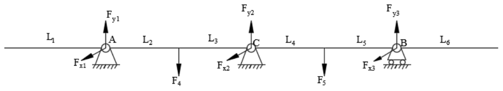
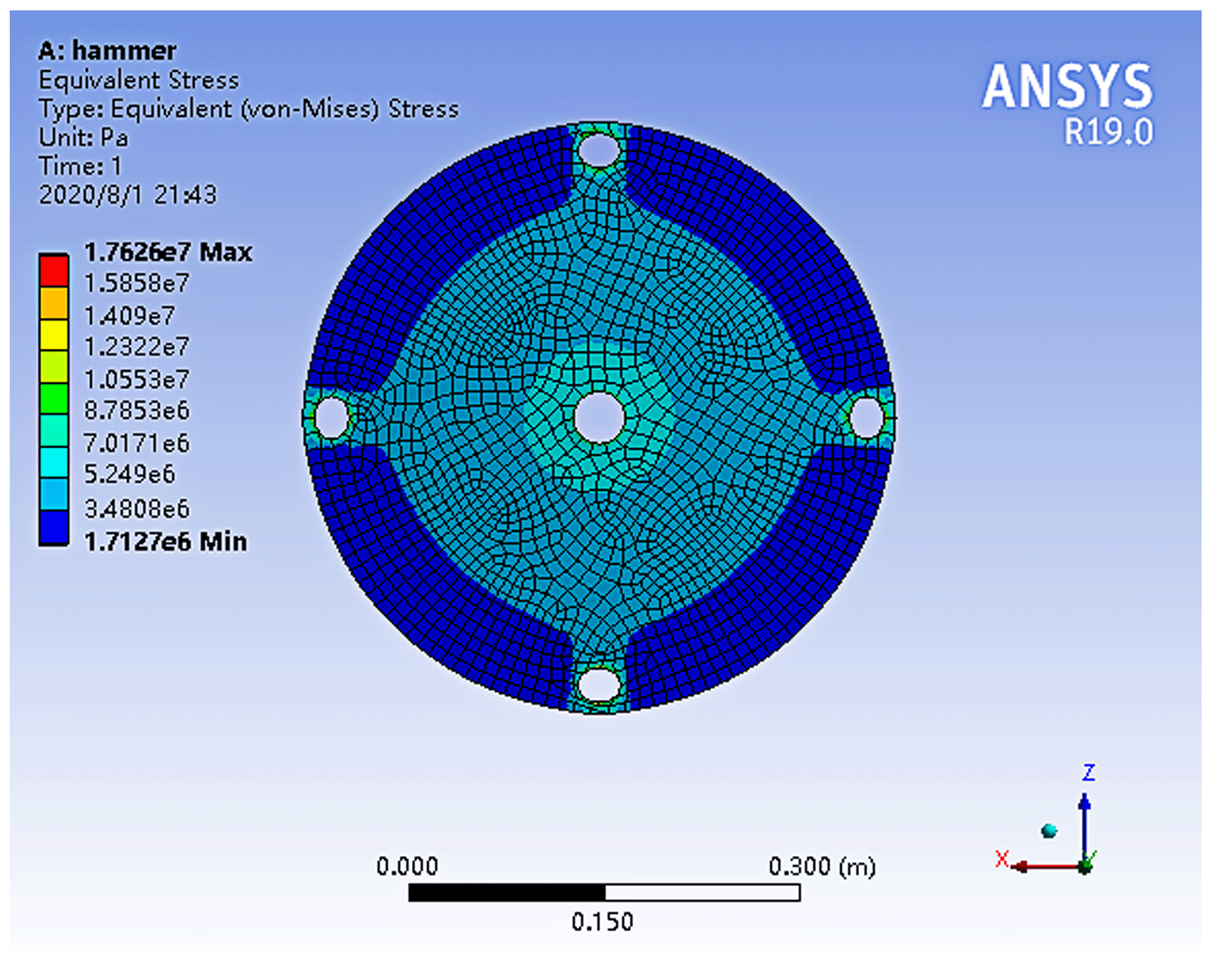

Figure 5 shows that L1=25 mm, mm, and L6=90 mm. The centrifugal force F0 of a single hammer slice is obtained as follows:
where m is the single hammer slice mass, w is the rotating angular velocity of the rotor system, and r is the distance from the center of the rotor to the center of the hammer slice centroid.
The hammer slice material is 65 Mn, the mass m of a single hammer slice is 0.034 kg, the rotor system speed n=2100 r/min, and rad/s. After calculation, r=333.40 mm, N, and N.
From the preceding information, the force balance and moment equations are as follows:
Figure 5 shows that the pin is a statically indeterminate beam, and the unique value of the force at each point of action cannot be determined. Thus, deflection is introduced. Assuming that the constraint on the middle hole is redundant, the deflection at point B is 0 (Jinglan et al., 2014), and the deflection at point B is the sum of the deflections of various forces at point B as follows:
F2y=3426.25 N and N are obtained.
When the hammer mill is in operation, the holes in the hammer slice are subjected to the centrifugal force generated by the hammer slice and the centrifugal force generated by the pin (Du et al., 2015). , mpin=0.150 kg, ωpin=219.91 rad/s, rpin=180 mm, Fpin=1305.70 N, and the centrifugal force of a single pin acting on each hammer framework is N.
In summary, the force on each pin hole in the middle hammer framework is FB=3861.00 N, and the force on each pin hole on the hammer framework on both ends is N. The stress conditions of the three hammer frameworks indicate that the middle hammer framework is the most stressed. Therefore, when performing static analysis on the hammer framework, the strength of the intermediate hammer framework should be analyzed.
Ansys is used to analyze the hammer framework. The stress distribution and deformation diagrams are as shown in Figs. 6 and 7. Note that the maximum stress is 33.7 MPa around the pin and spindle holes, and the maximum deformation is at the edge of the hammer framework. Hence, the design meets the requirements of strength and rigidity.
4.3 Modal analysis of the spindle
4.3.1 Preprocessing
By defining the element attributes of the Ansys Brick 8 node SOLID185 and the element material attributes, 40 Cr elastic modulus 2.11×10⁵ MPa, Poisson's ratio 0.29, and density 7.9 mg/cm3, the spindle model was set up and conducted free meshing with the check of the number of nodes (32) and number of units (12 154) in Ansys.
4.3.2 Modal analysis and calculation
To define the analysis type model, select the Block Lanczos modal extraction method and select the analysis mode order as 6 (Cheng, 2011). Then, fully constrain the face and set the gravity in the y direction, as shown in Table 2.

4.3.3 Solution
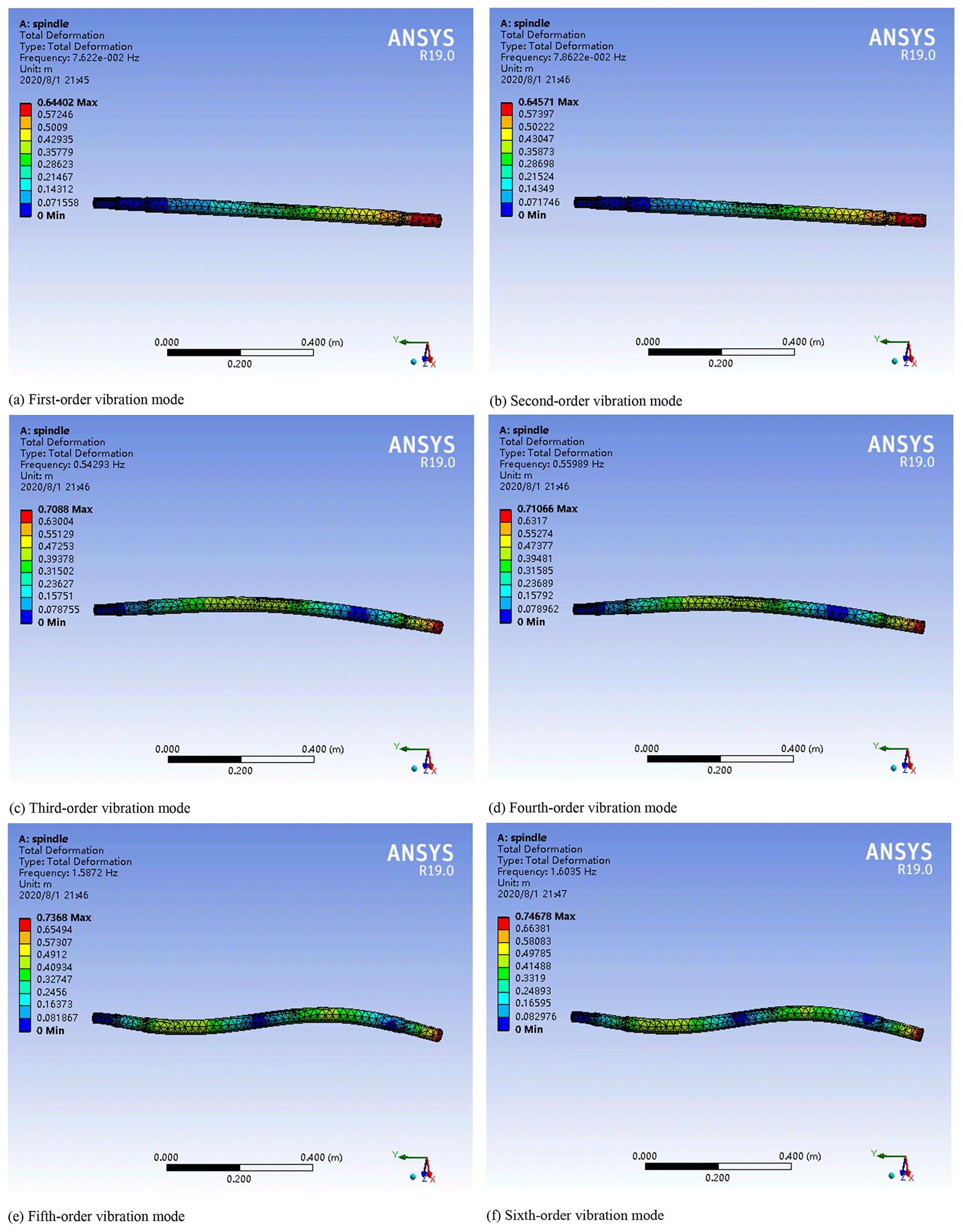
As shown in Fig. 8, the first- and second-order vibration mode is a vibration mode of a rigid body; in the third- and fourth-order vibration modes, the spindle appears to have a bending deformation, and in the fifth- and sixth-order vibration modes, the spindle appears to have a bending deformation, and the two ends of the spindle were bent to both sides. The designed rotating speed of the spindle is 2000 r/min, converted into an operating frequency of 66.7 Hz, which is substantially lower than the natural frequency of the spindle, which will not cause resonance (Wei et al., 2017).
5.1 Test purposes
The purpose of this experiment is to verify the accuracy of the simulation results and the crushing efficiency of the crushing mechanism.
5.2 Test conditions
In late straw graining, the crushing length of straw will significantly affect the efficiency of the graining process and the quality of the straw particles. This experiment selected the pass rate of the straw crushing length as the evaluation index of equipment operation.
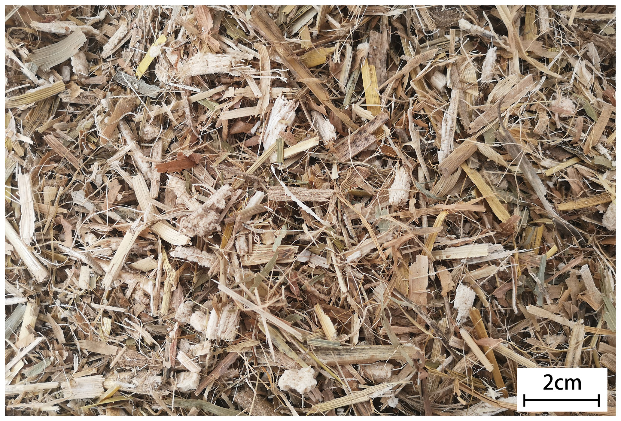
This test was based on the requirements of China National Standard GB/T 24675.6-2009, which is the “protective tillage machinery straw crushing and returning machine” standard, and those required for equipment granulation. The experiment was conducted at Nanjing Agricultural University. Corn stalk was processed using a harvesting and picking device (i.e., independently developed mobile pellet harvester), with a length of ≤5 cm and moisture content of 11.6 %, as shown in Fig. 9.
5.3 Test method
The crushing spindle adopts the test requirement of 2000 r/min. There are other test equipment, including a variable frequency motor, electronic scale, meter, stopwatch, and so on. The variable frequency motor was used to control the speed of the spindle. To ensure the accuracy of test results, six validation tests were conducted, with the average of each measurement and the test rate of corn straw crushing calculated. The amount of straw crushed in each test is 15 kg. From each straw crushed, a certain amount of straw crushed material was taken as a sample. The pass rate of the crushing length is calculated by weighing the total mass of the sample straw and mass of the unqualified straw (length is ≥ 10 mm). The calculation is as follows:
where ρ is the qualification rate of straw chopping in percent, m1 is the total mass of extracted chopped straw in grams, and m2 is the total mass of unqualified chopped straw in grams.
5.4 Test results and analysis
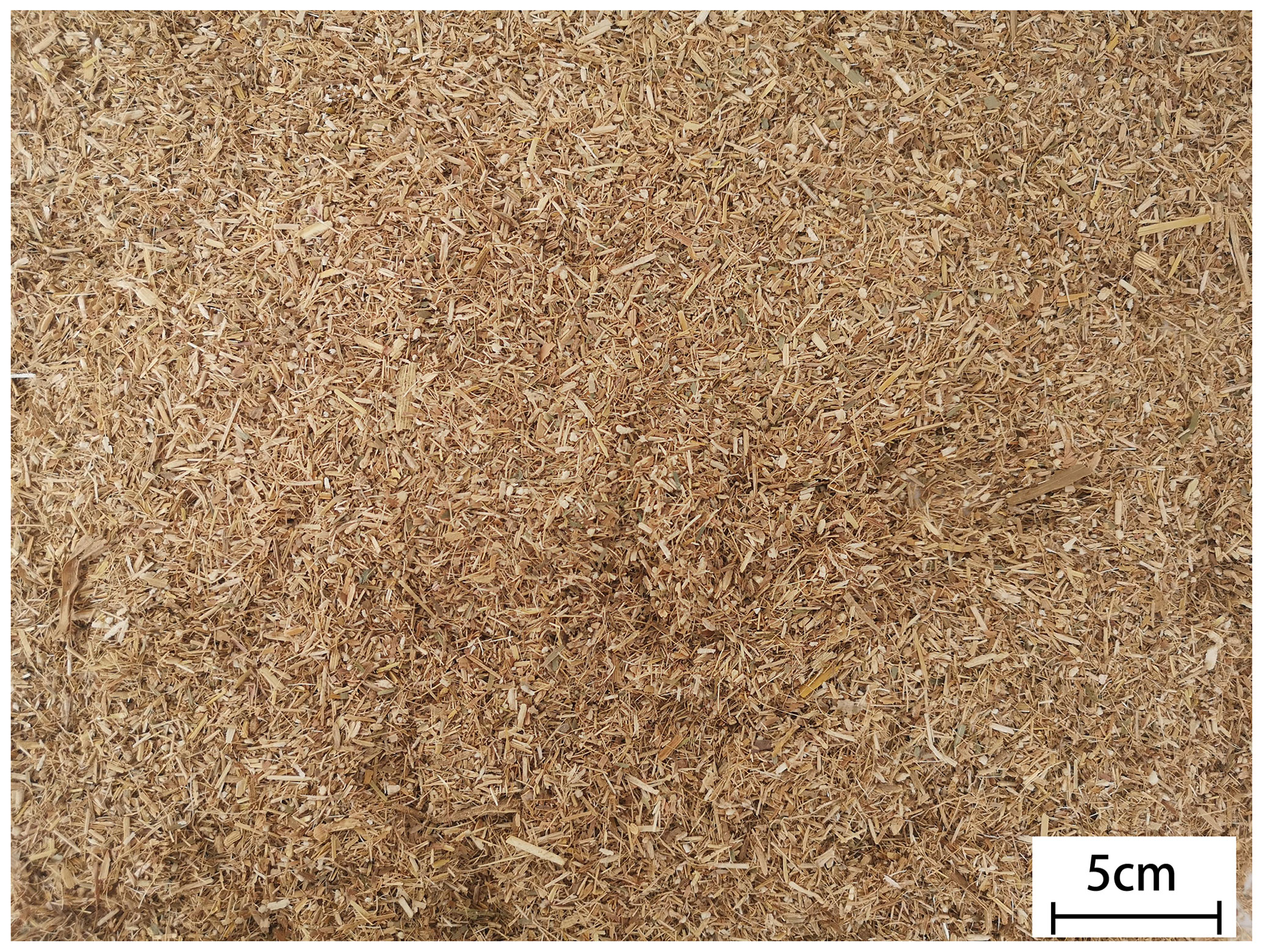
The crushing effect is shown in Fig. 10, and the test results are shown in Table 3.
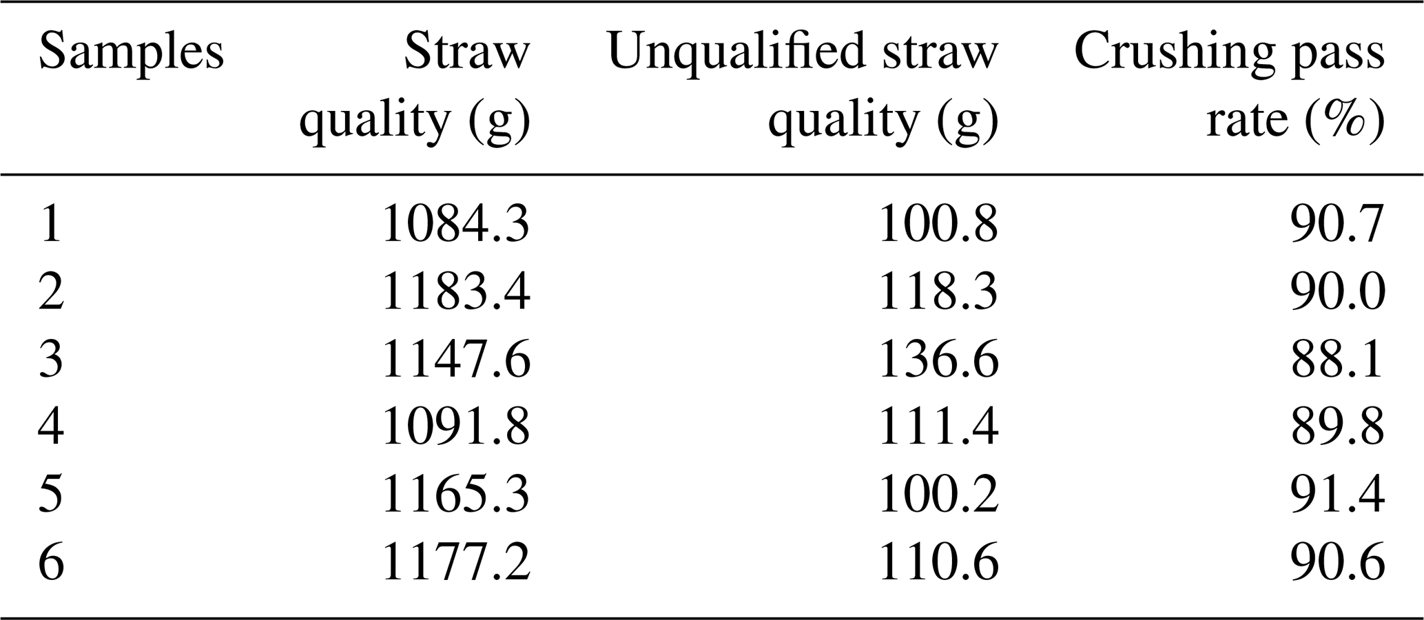
The test results show that the crushing device designed according to the simulation results meets the operation requirements. Moreover, the qualification rate of the straw crushing length is over 85 % (length is ≤ 10 mm), which meets the subsequent granulation requirements and requirements of the national technical specifications.
This study proposed and verified a new idea for the crushing system of a mobile pellet harvester. As the key components of the crushing mechanism, the theoretical design calculation was given, and Ansys was used to verify the feasibility of the design, specifically by computing the strength and stiffness. Field tests were conducted, and the test results met the requirements. This design can promote the further development of a mobile pellet harvester. With the development of agriculture in recent years, straw treatment has attracted considerable attention, even though current straw treatment methods are not perfect. Most of the straw processing equipment on the market is fixed and considerably bulky. A mobile pellet harvester is in its infancy, and there are still numerous problems. For future development, the same mobile pellet harvester can process more types of straw, and its volume will be smaller and more suitable for field work. Lastly, future scientific developments will enable the creation of numerous energy saving, reduced human effort, and favorable machines for the environment.
Ansys finite element analysis software was used to analyse the crushing mechanism. It can be downloaded from https://www.ansys.com/academic/students (last access: 19 July 2021).
No data sets were used in this article.
YG presented the overall structure. ZS designed the major work components. MX and MK did the mechanical analysis. RW and QZ did the prototype test.
The contact author has declared that neither they nor their co-authors have any competing interests.
Publisher's note: Copernicus Publications remains neutral with regard to jurisdictional claims in published maps and institutional affiliations.
The authors wish to thank Jinwu Wang, a senior engineer of Shandong Daye Co., Ltd., for his theoretical guidance in the design.
This work has been supported by the Jiangsu Agricultural Science and Technology Innovation Fund (grant no. CX (19)3071) and the high-level talent project of the Six Talent Peaks in Jiangsu Province (grant no. GDZB-023).
This paper was edited by Daniel Condurache and reviewed by two anonymous referees.
Cheng, K.: Finite Element Analysis and Structural Optimization of the Box on the ANSYS Workbench, Adv. Mat. Res., 211–212, 434–439, https://doi.org/10.4028/www.scientific.net/AMR.211-212.434, 2011.
Du, J., Han, B., Tian, H., Wang, P., Jiang, H., and Guo, K.: Analysis and Study of the Main Factors Affecting the Performance of Hammer Mill, Journal of Agricultural Mechanization Research, 3, 54–57, https://doi.org/10.3969/j.issn.1003-188X.2015.03.013, 2015.
Gomez, A. L., Canon, C. F., and Ramirez, D. E.: Hard faced welded tips in shredder hammers: Technical and economical performance, Int. Sugar J., 110, 335–340, https://doi.org/10.1021/jf0724320, 2008.
Hao, L., Shen, W., and Ban, T.: Research progress of the use of technology and crushing equipment on straw in China, Journal of Chinese Agricultural Mechanization, 39, 17–21, https://doi.org/10.13733/j.jcam.issn.2095-5553.2018.01.004, 2018.
Hill, T. M., Ii, H. G. B., Aldrich, J. M., and Schlotterbeck, R. L.: Effects of the amount of chopped hay or cottonseed hulls in a textured calf starter on young calf performance, J. Dairy Sci., 91, 2684–2693, https://doi.org/10.3168/jds.2007-0935, 2008.
Jia, S. H.: Virtual design and study of composite straw crusher's rotor based on Pro/E, Journal of Chinese Agricultural Mechanization, 35, 164–166, https://doi.org/10.13733/j.jcam.issn.2095-5553.2014.02.039, 2014.
Jian, X. K. and Liu, S. C.: Research Status and Development Prospect of Densified Biofuel, Biomass Chemical Engineering, 47, 54–58, https://doi.org/10.3969/j.issn.1673-5854.2013.02.011, 2013.
Jinglan, R., Zhang, L., and Zeng, G.: The dynamic analysis on the closed rotor of hammer mill, 10, 43–45, https://doi.org/10.7633/j.issn.1003-6202.2014.10.011, 2014.
Kaliyan, N. and Morey, R. V.: Factors affecting strength and durability of densified biomass products, Biomass Bioenerg., 33, 337–359, https://doi.org/10.1016/j.biombioe.2008.08.005, 2009.
Mani, S., Tabil, L. G., and Sokhansanj, S.: Effects of compressive force, particle size and moisture content on mechanical properties of biomass pellets from grasses, Biomass Bioenerg., 30, 648–654, https://doi.org/10.1016/j.biombioe.2005.01.004, 2006.
Miao, Z., Grift, T. E., Hansen, A. C., and Ting, K. C.: Energy requirement for comminution of biomass in relation to particle physical properties, Ind. Crop. Prod., 33, 504–513, https://doi.org/10.1016/j.indcrop.2010.12.016, 2011.
Quan, L., Tong, J., Zeng, B., and Chen, D.: Finite element mode analysis and experiment of corn stubble harvester, Transactions of the Chinese Society of Agricultural Engineering, 27, 15–20, https://doi.org/10.3969/j.issn.1002-6819.2011.11.003, 2011.
Saez-Trumper, D.: Online Disinformation and the Role of Wikipedia, arXiv [preprint], arXiv:1910.12596, 14 October 2019.
Shi, Z., Shao, Y., Fei, W., Wang, J., Sun, R., Song, C., and Xiang, L.: Study on the Situation and Countermeasures of Straw Comprehensive Utilization in China, Chinese Journal of Agricultural Resources and Regional Planning, 39, 30–36, https://doi.org/10.7621/cjarrp.1005-9121.20181005, 2018.
Stelte, W., Holm, J. K., Sanadi, A. R., Barsberg, S., Ahrenfeldt, J., and Henriksen, U.: Fuel pellets from biomass: The importance of the pelletizing pressure and its dependency on the processing conditions, Fuel, 90, 3285–3290, https://doi.org/10.1016/j.fuel.2011.05.011, 2011.
Sun, M., Xu, X., Wang, C., Bai, Y., and Wang, Y.: Environmental burdens of the comprehensive utilization of straw: Wheat straw utilization from a life-cycle perspective, J. Clean. Prod., 259, 120702, https://doi.org/10.1016/j.jclepro.2020.120702, 2020.
Tumuluru, J. S.: Effect of process variables on the density and durability of the pellets made from high moisture corn stover, Biosyst. Eng., 119, 44–57, https://doi.org/10.1016/j.biosystemseng.2013.11.012, 2014.
Wang, Q.: Design of Key Components of Straw Pulverizer, Agr. Eng., 8, 91–94, https://doi.org/10.3969/j.issn.2095-1795.2018.07.026, 2018.
Wang, Y., Wang, Y., and Liu, D.: Research and Development on Making Straw Pellet Pulverizer, Journal of Agricultural Mechanization Research, 31, 157–159, https://doi.org/10.3969/j.issn.1003-188X.2009.01.048, 2009.
Wei, S., Zhang, Y., Fu, C., Jia, F., and University, N. A.: Effect of Parameter Optimization on Crushing Effect of Straw Crusher, Journal of Agricultural Mechanization Research, 39, 158–162, https://doi.org/10.13427/j.cnki.njyi.2017.09.031, 2017.
Xiong, C. G., Xie, Z. Q., Wen-Yu, Y. I., Run-Qi, X. U., and Yao, J. X.: Study on Basic Characteristics of Crop Straw/Stalk Used as Biomass Energy Resources, Southwest China Journal of Agricultural Sciences, 23, 1725–1732, https://doi.org/10.3969/j.issn.1001-4829.2010.05.071, 2010.
Zhang, G. L., Zhang, Z. T., Sun, Z. B., Qu, B. X., and Xu, C. M.: Analysis of problems of biomass briquette production and application, Journal of Agricultural Mechanization Research, 33, 177–183, https://doi.org/10.3969/j.issn.1003-188X.2011.08.046, 2011.
Zhang, J., Wang, X., Chen, F., Jiang, Y., and Niu, C.: Study on working parameters of knife roller of field straw chopper for mulching or reclaiming, Transactions of the Chinese Society for Agricultural Machinery, 38, 82–85, https://doi.org/10.3969/j.issn.1000-1298.2007.06.021, 2007.
Zhang, L. and Jing-Lan, R.: The Analysis of Influence Factor and Research Stayus of Hammer Mill, Packaging and Food Machinery, 6, 55–57, https://doi.org/10.3969/j.issn.1005-1295.2013.06.014, 2013.
Zhou, Z., Duan, G., Hongjing, X. U., and Yue, L.: Study on reusable modeling simulation and optimization approach of hammer crushers, Mining & Processing Equipment, 39, 72–77, https://doi.org/10.16816/j.cnki.ksjx.2011.10.020, 2011.
Zong, Y. X., Wan, F. X., Jun, P. U., Huang, X. P., and University, G. A.: Research Situation of Biomass Pellet Forming Mechanism, Forestry Machinery & Woodworking Equipment, 44, 4–6, https://doi.org/10.13279/j.cnki.fmwe.2016.0063, 2016.
- Abstract
- Introduction
- Overall structure
- Design of the major work components
- Mechanical analysis of the important components
- Prototype test
- Conclusion
- Code availability
- Data availability
- Author contributions
- Competing interests
- Disclaimer
- Acknowledgements
- Financial support
- Review statement
- References