the Creative Commons Attribution 4.0 License.
the Creative Commons Attribution 4.0 License.
 | 04 Feb 2021
Design and multichannel electromyography system-based neural network control of a low-cost myoelectric prosthesis hand
Saygin Siddiq Ahmed
Ahmed R. J. Almusawi
Bülent Yilmaz
Nuran Dogru
This study introduces a new control method for electromyography (EMG) in a prosthetic hand application with a practical design of the whole system. The hand is controlled by a motor (which regulates a significant part of the hand movement) and a microcontroller board, which is responsible for receiving and analyzing signals acquired by a Myoware muscle device. The Myoware device accepts muscle signals and sends them to the controller. The controller interprets the received signals based on the designed artificial neural network. In this design, the muscle signals are read and saved in a MATLAB system file. After neural network program processing by MATLAB, they are then applied online to the prosthetic hand. The obtained signal, i.e., electromyogram, is programmed to control the motion of the prosthetic hand with similar behavior to a real human hand. The designed system is tested on seven individuals at Gaziantep University. Due to the sufficient signal of the Mayo armband compared to Myoware sensors, Mayo armband muscle is applied in the proposed system. The discussed results have been shown to be satisfactory in the final proposed system. This system was a feasible, useful, and cost-effective solution for the handless or amputated individuals. They have used the system in their day-to-day activities that allowed them to move freely, easily, and comfortably.
- Article
(2385 KB) - Full-text XML
- BibTeX
- EndNote


Annually, there are around 50 000 amputation cases in the USA alone (as reported by the National Center for Health Statistics; Bhubaneswarr et al., 2007). Moreover, there are over 1 million annual hand or limb amputations globally. Physical impairment can affect a person's life in their work, personal needs, and leisure activities. A lot of work and research has been done to aid these individuals in leading an everyday existence. Many amputees opt for prosthetic limbs (Hsu et al., 2006).
In this context, one study has investigated the use of forearm surface electromyography (sEMG) signals acquired by three pairs of surface electrodes to classify arm movements. Further, an artificial neural network is used to classify the signal features and subsequently recognize the performed action (Balbinot et al., 2013). Along this research line, Raurale et al. (2020) conducted real-time identification of active hand-movement EMG signals based on wrist–hand mobility for simultaneous control of prosthetic robotic hands (Raurale and Chatur, 2014). In another system, a fully wireless, mobile platform used for acquisition and communication of sEMG signals is embedded in a mobile control system, and Ottobock 13E200 EMG electrodes are used to acquire the EMG signals. The electrodes are attached to the patient's remaining forearm stump. In addition, a laptop is used to provide the required computational power for the control of the prosthetic robotic hand (Brunelli et al., 2015). In order to reduce costs, some studies have utilized an open-source design for the implementation of affordable, modular, compliant, and under-actuated prosthetic fingers that can aid amputees who suffer from partial amputations (e.g., amputations of one or several fingers of the human hand, except for the thumb) to regain lost dexterity (Kontoudis et al., 2015). Generally concerning a robotic prosthetic, the primary challenge involves developing a flexible experimental setup for the closed loop of a prosthetic device with integrated augmented reality that allows the extent and type of the provided visual and vibrotactile feedback to be changed.
Another work has discussed controlling the electronic devices by using myoelectric signals pointing to the development of a digital controlling interface by using the Myo gesture control armband system. PeopleBot was used, which is a robot designed for home needs, and the developed system allows one to control the movement of the robot and how the robot interacts with the environment, besides using an inertial measurement unit (IMU). The results provided excellent acquisition and processing of signals, with the ability to obtain new gestures in future (Morais et al., 2016).
A similar work for gesture recognition in the bio-robotics field is developed by presenting a low-cost sensor based on human gesture recognition for a game of hand cricket in which the players have pre-defined gestures and wear the Myo armband. Furthermore, it is responsible during every muscle action to determine the bio-potentials, and eight channels were screened and the data collected.
The proposed system used a support vector machine (SVM) to classify all the different gestures to find maximum accuracy, and the data go through a pre-processed feature extracted in MATLAB (Krishnan et al., 2017).
A work done recently by using a Myo gesture armband differentiates hand movements to move a 5-DoF Aideepen ROT3U robotic arm. The system is divided into three main parts: segmentation, feature extraction, and classification. The results showed that the extent of the frame performances has an important role in the accuracy of the system. It concluded that better results can be obtained by using SVM and linear discriminant analysis (LDA) classifiers (Hassan et al., 2019).
Another work was done by using the Myo armband to detect electrical activities where the Myo has sensors for EMG. The proposed system detected the EMG from different parts of forearm muscles; then, by using gyroscope and accelerometer sensors it is transferred to a computer and using the data set to control a robotic arm virtually using Unity 3D (Ganiev et al., 2016).
In one study, 13 volunteers participated in the experiments by controlling the Ottobock SensorHand Speed prosthesis. The results indicated that the recorded vibrotactile patterns were able to replace visual feedback (Ninu et al., 2014). In another study, in a multi-sensory, five-fingered bio-mechatronic hand with an sEMG interface, each finger was integrated with torque and position sensors that offered the hand more grasping patterns and complex control methods (Wang et al., 2010). Several studies have focused on the control approach as well. In general, the control design of a robotic arm employs fuzzy algorithms to interpret EMG signals from the flexor carpi radialis, extensor carpi radialis, and biceps brachii muscles. In one type of control approach, the control and acquisition system consists of a microprocessor, analog filtering, digital filtering, frequency analysis, and a fuzzy control system, and electromyographic grasp recognition together with an 8-bit microcontroller is used to control a veneered robotic hand to emulate six grasp types that are used for over 70 % of daily activities (Hidalgo et al., 2005; Kakoty et al., 2013).
Meanwhile, a new configuration of sEMG electrodes was reported to reduce interference resulting from electrode shifts depending on muscle movement. The authors suggested that optimizing electrode configuration can improve the EMG pattern discrimination, wherein the proposed electrode configuration has a reference value (Li et al., 2015). Another approach involves a hybrid methodology for performing tactile classification and feature extraction during a single grasp with a simple under-actuated robot hand. Two cooperating schemes are used, which are based on an advanced machine learning technique (random forests) and parametric methods that estimate object properties (Kakoty et al., 2013). Along these lines, another study (Bennett et al., 2015) has reported on the design of an anthropomorphic prosthetic hand that incorporates four motor units in a unique configuration to provide both precision and conformal grasp capability. Here, we remark that the most functional graspers are the ones that are obtainable at an affordable cost and have a low-cost design. Therefore, for aesthetic reasons, many people prefer artificial limbs that have less or zero functionality but that appear more human-like.
Nonetheless, a grasper that can perform many different tasks at a low price is also highly desirable. Hence, it is crucial to develop a low-cost robotic grasper that can complete everyday grasping tasks effortlessly. It is also noteworthy that almost all robotic hands designed in university research projects consist of numerous actuators and sensors, which makes them unsuitable for manufacturing along with being too expensive for the typical user. In general, the medical industry significantly benefits from providing low-cost portable systems that allow visualization efficiently, easily, and remotely while also providing quick access in real time, thereby enhancing the efficiency of doctors and specialists along with delivering more remarkable ability and care.
The achievement of their work is the classification of EMG signals based on a collection of EMG signals used for calculation, from the results obtained, and it was confirmed that it is possible to use a linear discriminant analysis classifier with satisfactory correctness and rate to deliver control of the motor components of a muscle. The achieved classification rate was around 88 %–91 %. In work done by Hussain et al., first, they evaluated many designs of prosthetic hands in both research area and commercial products. The work was proposed to include a four-faced actuating mechanism for the thumb and four fingers, which led to developing a double-gear mechanism. Also, their approach controlled an EEG to operate the prosthesis. They also presented comparisons of developed robotic arms in terms of performance parameters (Hussain et al., 2015). The work of the researchers Krausz and Rorrer (2015) was to design and fabricate a six degree-of-freedom (DoF) system, and the design was made open source. This hand has been developed for use by researchers in the field. There are two main benefits of this work: that the hand is cheap and open source (Krausz and Rorrer, 2016).
The objective of this work is to utilize EMG to control hand prosthesis, develop a path with a trajectory procedure, design EMG-controlled hand prosthesis for facilitating several hand gestures under different noisy situations, and develop an electronic interfacing circuit to the robot arm employing MATLAB/Simulink and a graphical user interface (GUI).
2.1 Mechanical hand design
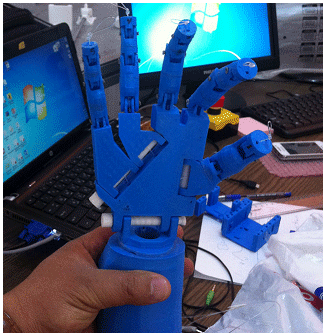
The model hand employed in the study was a 3D printed model of the Flexy Hand (Bonini et al., 2014). Therefore, the corresponding STL file was exported into the Makerbot platform and directly written with no scaling or modification to the size of the separate elements of the hand, as the printing of the complete hand has been completed and the finished hand was set up and a stretched disposable measuring system. Figure 1 shows a picture of the assembled 3D-printed hand. The measuring system was accustomed to clearing any excess material from the 3D printing that may hinder the fishing line's path through the inside of the hand and fingers and to help in threading the road through the palm of the hand. Every finger was set up with 60 cm (2 ft.) of cord to make sure that there would be excess material to pull down the length of the arm and fasten to the servos.
2.2 Motor control
A servo motor with three wires, power wire, ground wire, and pulse-width modulation (PWM) wire, was used to drive the hand. The PWM wire was connected to one of the six PWM ports of an Arduino UNO board. The power and ground wires of each servo were related to the horizontal positive and negative rows on the breadboard that was connected to a 6 V battery pack. The battery pack housed four 1.5 V D-size batteries. The PC module was plugged into the USB cable.
2.3 Hand control
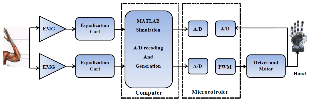
In this section, the microcontroller system (Arduino UNO) functions are used. Figure 2 shows the block diagram of the control circuit of the prosthesis. The use of an Arduino UNO unit in this study is to analyze the EMG signals acquired from the muscles. The motor handles the signal, and the UNO board is also used to send PWM information to the motor for hand control. The Myo armband is used to acquire EMG signals, and the signals are recorded in the MATLAB program for the training process. Another MATLAB program is designed to control the prosthetic hand. The Arduino microcontroller drives five servo motors to control the prosthetic hand's fingers.
2.4 Servo motor
The servo motor is a DC motor that contains a DC circuit to control the direction of rotation of the motor. There are two types of motor. (1) Standard: this motor is rotatable from 0∘ to 180∘ or from 0∘ to 120∘ in both the clockwise and anticlockwise directions. (2) Continuous: the continuous motor is rotatable from 0∘ to 360∘ in both directions. The standard servo type was used in this study as the movement of the fingers required rotation of 180∘. The servo motor rotation is achieved in units of the meter via a variable resistance that results in a change in the value of the outside voltage by the value of the resulting voltage. The servo circuit determines the precise axis of rotation. The control circuit within the servo motor receives the control signal from the Arduino microcontroller. Subsequently, the control circuit sends the signal to the motor to move the hand. The circuit diagram of the control architecture is illustrated in Fig. 3.
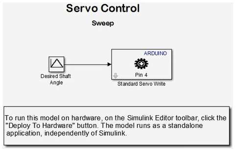
Figure 3Arduino servo circuit schematic.
The MATLAB program was created to achieve real-time operation of the hand. Simulink is a software package for modeling, simulating, and analyzing dynamic systems. The package supports linear and nonlinear systems modeled in continuous time, sampled time, or both of them by hybrid. Further, systems can be multi-rate, where they can have different parts that are being sampled or updated. Here, we note that a previous study has reported on a working hand prototype that has been developed and built for real-world applications; however, it is also necessary to create a simulated model. One of the benefits of using a simulated hand is that it allows stringent testing of the robotic hand in a controlled environment. In addition, hands that require advanced equipment can be measured in the simulation without the worry of damaging the actual hand. Figure 4 shows images of the robotic hand during various construction steps.

Another benefit of having a Simulink program of the hand model is that it allows representation of the results as functions of parameters (such as the weight or type of material) to work on further improvements. Lastly, the grasp quality and optimization of the finger positions for different grasps are other crucial aspects that can be tested with a good model. The Simulink program is designed for multidomain simulation and model-based design. As mentioned previously, Simulink can simulate and generate automatic code and allows various tests to be conducted along with verification of the embedded systems. Further, Simulink enables users to incorporate their MATLAB algorithms into models and export the simulation results to MATLAB for additional analysis. Figure 5 shows the proposed design and the test robot hand wiring for open and close movements.

The block diagram shows the connection between Arduino and a Myoware sensor with the application of MATLAB Simulink. The Simulink program consists of the following commands: constant, Slider Gain, (Sum, Add, Subtract, and Sum of Elements), Sine Wave, and Arduino IO servo Write. The constant is used for generating a real or complex constant value. The Slider Gain is used for varying the scalar gain during the simulation by using the slider; this block has one input and one output. The sine wave is used for generating a sinusoidal waveform, thus indicating that the output of this block is sinusoidal. The sine wave and Slider Gain signals are directed to the mixer, whose output is the summation of the sine wave and Slider Gain signals. The output of the mixer forms the input of the servo Write.
In this study, an EMG shield is used to obtain the signals from the arm muscles. Because the signals were not very clear, we used another high-sensitivity device to receive clear signals, as shown in Fig. 6: the green, purple, blue, and red waves represent the biceps, triceps, root mean square (rms) biceps, and rms triceps signals, respectively.
where N is the length of the signal and Xk represents the EMG signal in a segment. A simple way to measure the level of muscle activity is an absolute value, and this feature is standard for use in myoelectric control. This feature is used for all classification in this project.
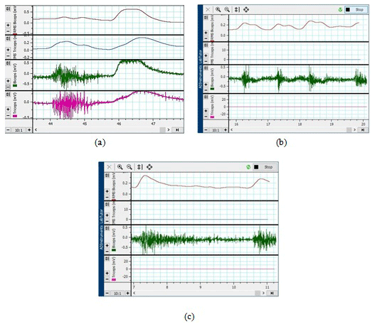
Figure 6(a) Signals obtained from the arm during hand close and open, (b) thumb signal, and (c) signals from four fingers.
Root mean square:
Slope sign change:
where
Waveform length:
Zero crossings:
where
Wilson amplitude:
where
Variance:
Figure 6b depicts the signals corresponding to the movement of the thumb. The green wave represents the biceps signal, and the red wave represents the rms biceps signal. Further, Fig. 6c illustrates the signals corresponding to the movement of the four fingers. Again, the green and red waves represent the biceps and rms biceps signals, respectively. Figure 7 shows the Myoware muscle device, which was finally used for signal acquisition; the device can acquire the required signals and subject them to frequency domain or EMG fast Fourier transform (FFT) operations, with the corresponding result inputted to the MATLAB program for hand control and signal analysis.

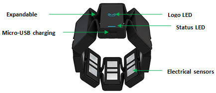
The Myo armband is a device for hand gesture recognition and arm movement tracking. The goal of Myo is to enable ease of use and control through an external device such as PC, smartphones, and other products by using hand gestures. The Myo armband finds and detects electrical activity in the muscles of the forearm. It should be noted that the forearm muscles are quite different from each other, and every muscle incorporates a different arrangement. These muscles control various motor functions, such as the activities of the wrist, moving fingers, making a fist, or turning to a side.
In Fig. 8 of the Myo armband device, Myo contains eight IMU sensors, which were specially developed by Thalmic Labs. Since the old diagnostic technique is massive and costly, it is not appropriate for such a use case. Moreover, Thalmic Labs were much challenged because of human anatomy, and structure differs from one individual to another. Therefore, they developed sensors that can overcome problems like indirect contact with human skin, for example, due to hair cover or skin defects. To handle this issue of human physiology individuality, the developers at Thalmic Labs use machine learning algorithms.
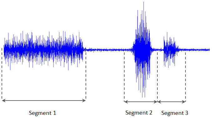
The Myo armband is efficient at storing EMG information at a frequency of 200 Hz but is controlled to 50 Hz while also recording positional information. The feature selected for cataloging was the mean total rate of the EMG signal. The stream of detailed EMG signals was segmented to analyze the mean average as the frequent cases: speed and accuracy are the criteria for selecting the segment size. A lengthier segment might afford a good mean value by providing more data points in the signal, but using more rambling segments could also decrease the structure's reply time, as seen in Fig. 9. The overlying lengthier segments can be used by having a lesser impact on structure reply time (Smith et al., 2011).
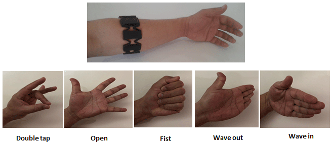
The Myo gesture armband will be used for the sensor system. The Myo gesture armband uses EMG sensors to sense the movements of various muscles in the forearm, and the software translates EMG signals to five different hand gestures: open hand, closed fist, hand bent right, hand bent left, and touching the thumbs and index fingers. It also includes a nine-axis IMU containing a three-axis accelerometer, gyroscope, and magnetometer. The sensors are used to detect movement in the x axis and y axis and rotation along the z axis.
The data are sent to the computer through a Bluetooth transmitter to a USB dongle, and the Myo software interprets the signal. The user will wear the armband around his or her upper forearm, and a built-in Bluetooth connection sends the data to the laptop. The laptop will run the Myo software to interpret the Bluetooth signals from the Myo armband and then pass these data to the control algorithm. The interface between the sensor and control systems is wireless, making it convenient for the user, and it can be calibrated to work with different individuals.
Myo possessed five gestures, which may be found in Fig. 10. Also, since Myo is a new device that was formally released in the summer of 2014, there is presently still development work being done by Thalmic Labs.
To prevent the misclassification of hand movements as a gesture, Myo incorporates a protection mechanism. The mechanism keeps Myo in standby mode awaiting only one motion, notably the double-regulator gesture, whereas all totally different gestures the unit ignored. Once the unlocking gesture is created, Myo starts to look for various hand gestures for many seconds. If for this duration no motion is made, Myo will lock itself all over again. This protection mechanism is modified, disabled, or extended from a developer's purpose of reading.
Overall system
The proposed system is divided into subsystems that work together to provide the functionality described in the engineering specifications. The four systems are the sensor system (Myo armband), control system (Excel, MATLAB, rms, NNT, recognition, and application to hand), the microcontroller (Arduino UNO), and the robotic arm. Figure 11 shows a breakdown of the overall system into the subsystems. The rest of this section describes the interfaces between each of the subsystems and their functionality.
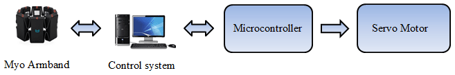
Figure 12 shows the block diagram of the control circuit of the prosthesis. We used an Arduino UNO unit in this study to analyze the EMG signals acquired from the muscles. The motor handles the signal, and the UNO board is also used to send PWM information to the motor for hand control.

The designed system has been implemented to achieve the target objectives. The mechanism of the system is emulated by printing a 3D prototype by using Myo armband sensors and being placed on the subject's arm. The obtained EMG signal is captured and is saved in an Excel file with a rate of 200 samples per second. The next step is using these samples to train the system by using the neural network algorithm and then analyzing them using Arduino. The controller will be responsible for triggering the servo motors to move the hand.
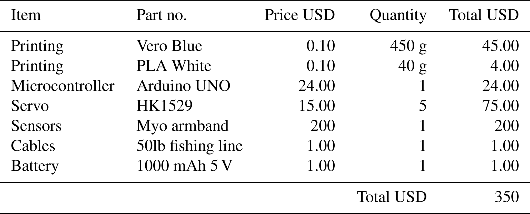
Table 1 lists the cost breakdown of the entire system, including the price of 3D printing. The prices of electronic components (resistors, capacitors, wires, solder) and mechanical components (screws, nuts, bolts, crimps, silicone) are not listed since they can be acquired easily from campus laboratories and machine shops. The cost of the project stayed well within the estimated limit. Compared to the existing advanced robotic hands that are available on the market, which cost around USD 90 000, a USD 350 robotic hand solution seems more viable to the general population of users.
Table 1Cost breakdown of all the materials used in the 3D-printed robotic hand.
Levenberg–Marquardt algorithm
The Levenberg–Marquardt algorithm is matched with the typical technique for resolving nonlinear least squares problems. The gradient descent and Gauss–Newton methods work together to make a mixture of them. The Levenberg–Marquardt algorithm presents an adaptive behavior concurring with the distance of the solution so that it can be guaranteed the solution in several situations (Hagan and Menhaj, 1994). Belief propagation (BP) in Gauss–Newton gave better results and was more accurate; however, BP in gradient descent is far from the solution, and it is relatively slow (Kwak and Song, 2015). In the Levenberg–Marquardt algorithm, computation of the approximate Hessian given in Eq. (8) is complete, and the gradient is calculated as shown in Eq. (9).
The e represents network errors, and J is the Jacobian matrix. The Levenberg–Marquardt algorithm uses this approximation in Eq. (10).
where +1 is a new weight that is calculated as the gradient function of the current weight Xk using the Newton algorithm.
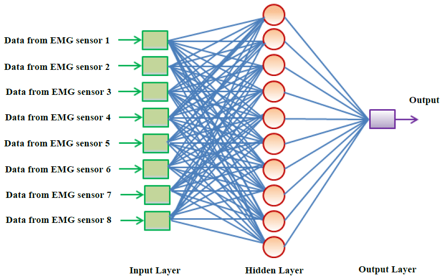
The design topology of the neural networks was designed as 8 input and 10 hidden layers, with one output node. The coaching times of the networks were assessed in a very massive direct one to 60 s, and it absolutely was restricted to 10 s. Ten-fold cross-validation was applied, and the validation set was also not employed in the experiments as shown in Fig. 13.
In this section, we compare the performances of our device and other existing devices on the market. Here, we remark that while our hand design is based on the ideas underlying the typically manufactured industrial robotic hand, we have also added a servo motor and EMG-based grip control in order to improve the device performance as well as ensure weight reduction relative to the weights of previously manufactured hands. The full weight of our device is 500 g, and the cost is as low as USD 250. These benefits are possible due to the use of EMG and grip control. Table 2 compares our device with specific other devices on the market. Comparison parameters include type, weight, and grip pattern along with other key parameters. From the table, it was evident that our device is more feasible for practical applications than other existing devices. In terms of device weight, our hand lies in the weight range of the myoelectrically controlled powered hand prosthetic and BeBionic (RSL Stepper). Their weights are considered suitable for prosthetic hands. Overall, our findings indicate that the proposed robotic hand delivers satisfactory performance, particularly in terms of improved controllability and perceptibility over other devices. An added benefit is the fact that our device is less expensive than other devices.
Table 2Comparison of existing commercial myoelectric prosthetics and our design.
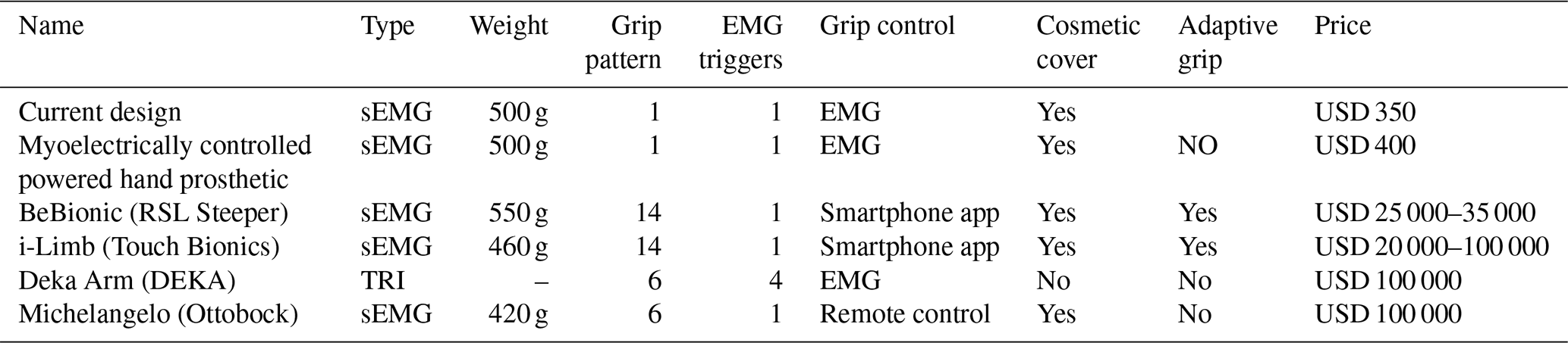
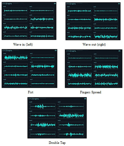
Figure 14 shows the results of the eight electromyogram sensors of the Myo armband in each gesture. It can be seen that in each sign, different electromyogram sensors have changed the result. Subdivision one shows the results from eight electromyogram sensors in five other gestures. In subdivision two, charts show data from the “wave left hand” gesture and display which of the eight parts of the forearm are electrically activated. The electrode voltage is shown in microvolts (µV), which was obtained using the Myo data capture tool. The signals were classified according to the corresponding muscle positions and were used to control the hand. The received signals were fed to a microcontroller (Arduino UNO), which allowed the myoelectric hand to respond to the signals from the muscles accurately. This paper showed how to control a robotic arm by using the electromyography sensor. Thanks to the EMG sensor, we get clear and essential data. The collected data are used for controlling the robotic arm. Arduino UNO is used as a microcontroller. It provides wireless communication between the robotic arm and Myo armband. With this system, the movement of the robotic arm has been successfully controlled according to the user's hand motions. Therefore, a robotic arm based on EMG is more helpful for use in the case of hand amputees.
9.1 Recording of EMG data
A outlines the electromyogram for each motion. As stated previously, the electromyogram sensor is comprised of eight parts with dissimilar information for each sensor, as can be seen in Fig. 15. Results show charts to check the activation rates of the gesture to “wave right”. For this gesture, parts 3, 4, and 5 are electrically activated and features 1, 2, 6, 7, and 8 are inactive.
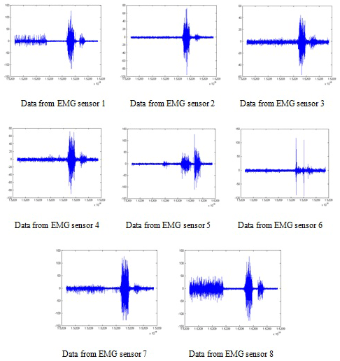
Figure 15Results of EMG recording of eight electrodes taken from the forearm. Note that the recording patterns are different.
9.2 Classification
All classifications in the data organization were made using an ANN, which has been created for every individual. All ANNs were created in MATLAB by using the nprtool interface. Using the Myo armband, a huge data set was analyzed as the person succeeded in each movement twice with a resting interval between them. The stored training data with compliant class labels are fed to the ANN training and split into three different stages. The training, validation, and test set consisted of 70 %, 15 %, and 15 % of the total collection, respectively.
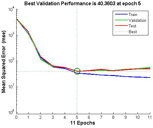
In Fig. 16, the performance plot shows, however, that the network's mean square error drops quickly as a result of it learning. The blue line indicates the decreasing error in the employment information, the mete shows the validation error employment stops once the validation error stops decreasing, and the line shows the error on taking a glance at the information, indicating however that the network will generalize well to new information.
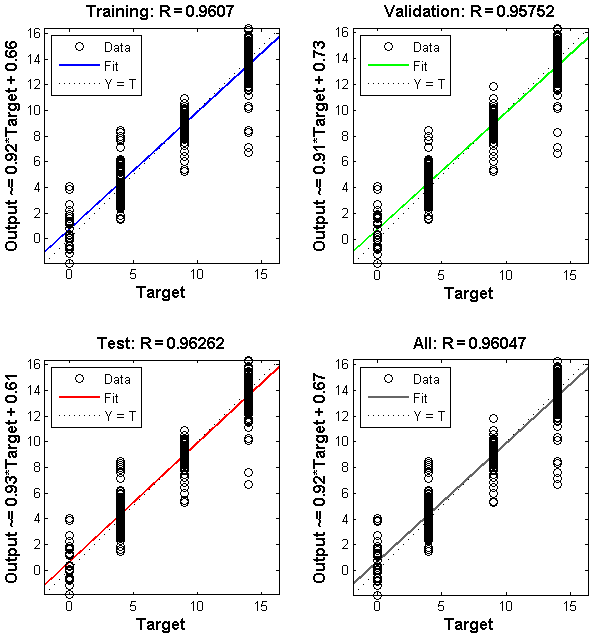
In Fig. 17 the regression plots show the neural network productions with relevance targets for coaching, validation, and check sets. For an improved match, the information needs to fall on a 45∘ line, whereas the neural network outputs a square measure capable of the targets. Here, the match is much higher for all knowledge sets, with R values in every case of 0.96 or higher.
It is a lot of better that I have around 450 data points close to the zero bin and around 350 data points with the flow. Note that in Fig. 18 there is much concentration around zero, which means the data are correct, and we set fewer errors compared to what it was earlier because the training data are fewer. The yellow bar indicates a zero error.

In Fig. 19 is a time series, so the error is a yellow color, and I have the training target represented in blue and the training output defined in blue plus the validation and this one, so overall the black color is the response. However, in this and in a few other cases, you see that the error is greater, and that is because we need to check what the validation target or the test target was, so it was mixed up in a lot of these cases, but overall if you notice the target minus output, most of the error is less than 20, which means that the classification is reasonably good.

A list is then compiled using these lists. The motion classification, as mentioned earlier, is performed, and the data are added to the set of classification lists as the five most recent classifications. The last added classification is assigned the most weight. With the addition of the latest classification, the list is updated because the oldest value is removed. This technique is somewhat time-consuming as a movement should be cataloged a minimum of three times to realize the bulk and to have an effect on the category label. However, it conjointly makes the system a lot stronger, with the unvarying nature preventing misclassifications.
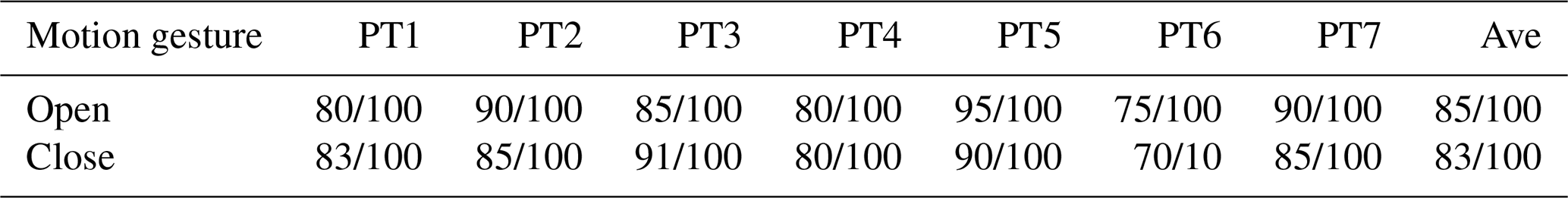
Due to an experimental limitation and difficulties or complications in reliably performing each gesture with different users, the latency check was solely done on one user. Every gesture was performed five times from an amount of rest and control until the motion completion time could be established. In contrast, the myogram activity and sophistication labels tags were continuously recorded. Table 3 shows the results of testing the hand on seven persons who were missing an arm. The data set is for two movements, namely the closing and opening of the hand. Some of the results have different rates of errors due to errors beyond the control of the designed system. One of the common reasons is the differences in the human muscles.
In this study, a program is designed for the myoelectric hand with two control pathways, one for the thumb (controlled utilizing medium nerves) and the second for the rest of the fingers (owned by the side nerves). The robotic hand was first printed with the use of a 3D printer, and the finger and thumb signals were subsequently recorded separately. Next, the biceps and triceps muscle signals were analyzed in order to obtain the significant signal peak points to convert them to Excel data. The signals were classified according to the corresponding muscle positions and were used to control the hand by applying an artificial neural network method. The obtained signals were fed to a microcontroller (Arduino UNO), which allowed the myoelectric hand to respond to the signals from the muscles accurately. In summary, the results show a cost-effective and straightforward prosthetic hand can significantly contribute to the development of robotic prosthesis. As future work, it is recommended to improve the architecture of the electronic circuit hardware such that the prosthetic hand can operate in a portable way without a computer (PC).
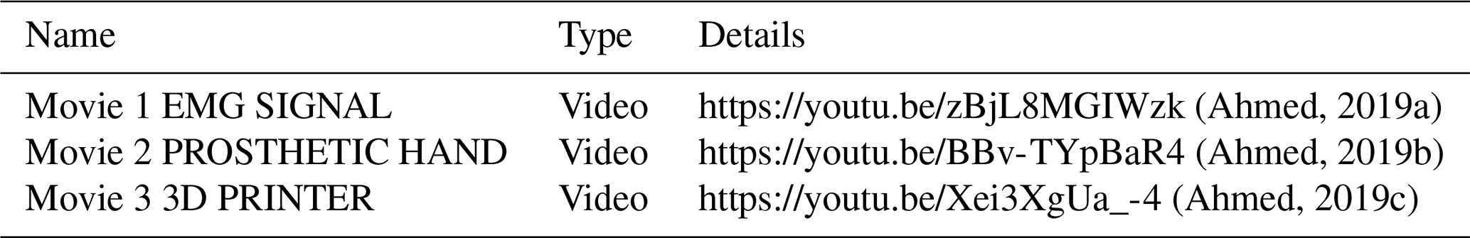
Video records of this article can be accessed online according to the mentioned hyperlinks in Table A1.
The code and the data used for this study are not publicly available. For further information, please contact the corresponding author.
See Appendix A for further information on Movies 1–3 (Ahmed, 2019a, b, c).
ND and BY performed the measurements and reviewed the work, SSA and ARJ were involved in planning and processed the experimental data, performed the analysis, and drafted the manuscript, and all the authors discussed the results and commented on the manuscript.
The authors declare that they have no conflict of interest.
This paper was edited by Daniel Condurache and reviewed by two anonymous referees.
Ahmed, S. S.: EMG SIGNAL 1, available at: https://youtu.be/zBjL8MGIWzk (last access: 6 July 2020), 2019a.
Ahmed, S. S.: PROSTHETIC HAND, available at: https://youtu.be/BBv-TYpBaR4, last access: 30 December 2019b.
Ahmed, S. S.: 3D PRINTER, available at: https://youtu.be/Xei3XgUa_-4, (last access: 17 December 2020), 2019c.
Balbinot, A., Júnior, A. S., and Favieiro, G. W.: Decoding arm movements by myoelectric signal and artificial neural networks, Intelligent Control and Automation, 4, 87–93, https://doi.org/10.4236/ica.2013.41012, 2013.
Bennett, D. A., Dalley, S. A., Truex, D., and Goldfarb, M.: A multigrasp hand prosthesis for providing precision and conformal grasps, IEEE-ASME T. Mech., 20, 1697–1704, https://doi.org/10.1109/TMECH.2014.2349855 2015.
Bhuvaneswar, C. G., Epstein, L. A., and Stern, T. A.: Reactions to amputation: recognition and treatment, Primary care companion to the Journal of clinical psychiatry, 9, 303–308, https://doi.org/10.4088/PCC.v09n0408, 2007.
Bonini, N., Iyer, N., Kim, D., Mathison, K., and Wellons, L.: Robotic Hand in Motion Using Arduino-Controlled Servos, New Jersey Governor's School of Engineering and Technology, 2014.
Brunelli, D., Tadesse, A. M., Vodermayer, B., Nowak, M., and Castellini, C.: Low-cost wearable multichannel surface EMG acquisition for prosthetic hand control, in: 6th International Workshop on Advances in Sensors and Interfaces (IWASI), Gallipoli, Italy, 18–19 June 2015, 94–99, 2015.
Ganiev, A., Shin, H.-S., and Lee, K.: Study on virtual control of a robotic arm via a Myo armband for the self-manipulation of a hand amputee, International Journal of Applied Engineering Research, 11, 775–782, 2016.
Hagan, M. T. and Menhaj, M. B.: Training feedforward networks with the Marquardt algorithm, IEEE T. Neural Networ., 5, 989–993, https://doi.org/10.1109/72.329697, 1994.
Hassan, H. F., Abou-Loukh, S. J., and Ibraheem, I. K.: Teleoperated robotic arm movement using electromyography signal with wearable Myo armband, Journal of King Saud University-Engineering Sciences, 32, 378–387, https://doi.org/10.1016/j.jksues.2019.05.001, 2019.
Hidalgo, M., Tene, G., and Sanchez, A.: Fuzzy control of a robotic arm using EMG signals, in: International Conference on Industrial Electronics and Control Applications Quito, Ecuador 29 November–2 December 2005, 6 pp., 2005.
Hsu, M. J., Nielsen, D. H., Lin-Chan, S. J., and Shurr, D.: The effects of prosthetic foot design on physiologic measurements, self-selected walking velocity, and physical activity in people with transtibial amputation, Arch. Phys. Med. Rehab., 87, 123–129, https://doi.org/10.1016/j.apmr.2005.07.310, 2006.
Hussain, R., Shahid, M. A., Khan, J. A., Tiwana, M. I., Iqbal, J., and Rashid, N.: Development of a low-cost anthropomorphic manipulator for commercial usage, In International Symposium on Innovations in Intelligent SysTems and Applications (INISTA), Madrid, Spain, 2–4 September 2015, 1–6, 2015.
Kakoty, N. M., Kaiborta, M., and Hazarika, S. M.: Electromyographic grasp recognition for a five fingered robotic hand, IAES International Journal of Robotics and Automation (IJRA), 2, 1–10, https://doi.org/10.11591/ijra.v2i1.pp1-10, 2013.
Kontoudis, G. P., Liarokapis, M. V., Zisimatos, A. G., Mavrogiannis, C. I., and Kyriakopoulos, K. J.: Open-source, anthropomorphic, underactuated robot hands with a selectively lockable differential mechanism: Towards affordable prostheses: in IEEE/RSJ International Conference on Intelligent Robots and Systems (IROS), Hamburg, Germany, 5857–5862, 2015.
Krausz, N. E. and Rorrer, R. A.: Design and fabrication of a six degree-of-freedom open source hand, IEEE T. Neur. Sys. Reh., 24, 562–572, https://doi.org/10.1109/TNSRE.2015.2440177, 2015.
Krausz, N. E. and Rorrer, R. A.: Design and fabrication of a six degree-of-freedom open source hand, IEEE Transactions on Neural Systems and Rehabilitation Engineering, 24, 562–572, https://doi.org/10.1109/tnsre.2015.2440177, 2016.
Krishnan, K. S., Saha, A., Ramachandran, S., and Kumar, S.: Recognition of human arm gestures using Myo armband for the game of hand cricket, in: IEEE International Symposium on Robotics and Intelligent Sensors, Ottawa, ON, Canada, 5–7 October 2017, 389–394, 2017.
Kwak, N. J. and Song, T. S.: Human action recognition using accumulated moving information, International Journal of Multimedia and Ubiquitous Engineering, 10, 211–222, https://doi.org/10.14257/ijmue.2015.10.10.22, 2015.
Li, Z., Li, G., Jiang, G., Fang, Y., Ju, Z., and Liu, H.: Computation of grasping and manipulation for multi-fingered robotic hands, J. Comput. Theor. Nanos., 12, 6192–6197, https://doi.org/10.1166/jctn.2015.4655, 2015.
Morais, G. D., Neves, L. C., Masiero, A. A., and de Castro, M. C. F.: Application of Myo Armband System to Control a Robot Interface, in: 9th International Joint Conference on Biomedical Engineering Systems and Technologies, Rome, Italy, February 2016, 227–231, 2016.
Ninu, A., Dosen, S., Muceli, S., Rattay, F., Dietl, H., and Farina, D.: Closed-loop control of grasping with a myoelectric hand prosthesis: Which are the relevant feedback variables for force control, IEEE T. Neur. Sys. Reh., 22, 1041–1052, https://doi.org/10.1109/TNSRE.2014.2318431, 2014.
Raurale, S. A. and Chatur, P. N.: Identification of real-time active hand movements EMG signals for control of prosthesis robotic hand, in: International Conference on Computation of Power, Energy, Information and Communication (ICCPEIC), Chennai, India, 16–17 April 2014, 482–487, 2014.
Raurale, S. A., McAllister, J., and del Rincon, J. M.: Real-Time Embedded EMG Signal Analysis for Wrist-Hand Pose Identification, IEEE Transactions on Signal Processing, 68, 2713–2723, https://doi.org/10.1109/tsp.2020.2985299, 2020.
Smith, L. H., Hargrove, L. J., Lock, B. A., and Kuiken, T. A.: Determining the optimal window length for pattern recognition-based myoelectric control: balancing the competing effects of classification error and controller delay, IEEE T. Neur. Sys. Reh., 19, 186–192, https://doi.org/10.1109/TNSRE.2010.2100828, 2011.
Wang, X., Liu, Y., Yang, D., Li, N., Jiang, L., and Liu, H.: Progress in the biomechatronic design and control of a hand prosthesis, in: IEEE/RSJ International Conference on Intelligent Robots and Systems, Taipei, Taiwan 18–22 October 2010, 5880–5885, 2010.
- Abstract
- Introduction
- Materials and methods
- MATLAB programming
- EMG signals
- Myo armband muscle sensors
- Design
- Cost analysis
- Artificial neural networks
- Results
- Conclusion
- Appendix A: Index to video records
- Code and data availability
- Video supplement
- Author contributions
- Competing interests
- Review statement
- References