the Creative Commons Attribution 4.0 License.
the Creative Commons Attribution 4.0 License.
 | 15 Jun 2021
An innovative equivalent kinematic model of the human upper limb to improve the trajectory planning of exoskeleton rehabilitation robots
Qiaolian Xie
Qingxin Zeng
Hongliu Yu
Zhijia Shen
Upper limb exoskeleton rehabilitation robots have been attracting significant attention by researchers due to their adaptive training, highly repetitive motion, and ability to enhance the self-care capabilities of patients with disabilities. It is a key problem that the existing upper limb exoskeletons cannot stay in line with the corresponding human arm during exercise. The aim is to evaluate whether the existing upper limb exoskeleton movement is in line with the human movement and to provide a design basis for the future exoskeleton. This paper proposes a new equivalent kinematic model for human upper limb, including the shoulder joint, elbow joint, and wrist joint, according to the human anatomical structure and sports biomechanical characteristics. And this paper analyzes the motion space according to the normal range of motion of joints for building the workspace of the proposed model. Then, the trajectory planning for an upper limb exoskeleton is evaluated and improved based on the proposed model. The evaluation results show that there were obvious differences between the exoskeleton prototype and human arm. The deviation between the human body and the exoskeleton of the improved trajectory is decreased to 41.64 %. In conclusion, the new equivalent kinematics model for the human upper limb proposed in this paper can effectively evaluate the existing upper limb exoskeleton and provide suggestions for structural improvements in line with human motion.
- Article
(4193 KB) - Full-text XML
- BibTeX
- EndNote


Upper limb exoskeleton rehabilitation robots have become more popular because they can not only provide adaptive training and highly repetitive motion but also enhance the self-care capabilities of patients with a loss of motor function (Jarrasse et al., 2010; Côté-Allard et al., 2018; Zhang et al., 2018). The design of upper limb exoskeletons should be especially considered because they interact directly with the human body (Esmaeili et al., 2011; Gopura et al., 2011). The number of degrees of freedom (DOF), range of motion (ROM) of joints, safety, comfort, low inertia, and adaptability to the human body should be especially considered in the design of these exoskeletons (Meng et al., 2018; Maciejasz et al., 2014). In particular, it is necessary that the movement of the exoskeleton should stay in line with the human arm. Misalignment may cause many problems, such as the external force between the exoskeleton and the arm, the inaccurate control output caused by the error of the measurement position, and decreased safety (Lo and Xie, 2012; Schiele and Helm, 2006; Rocon et al., 2007).
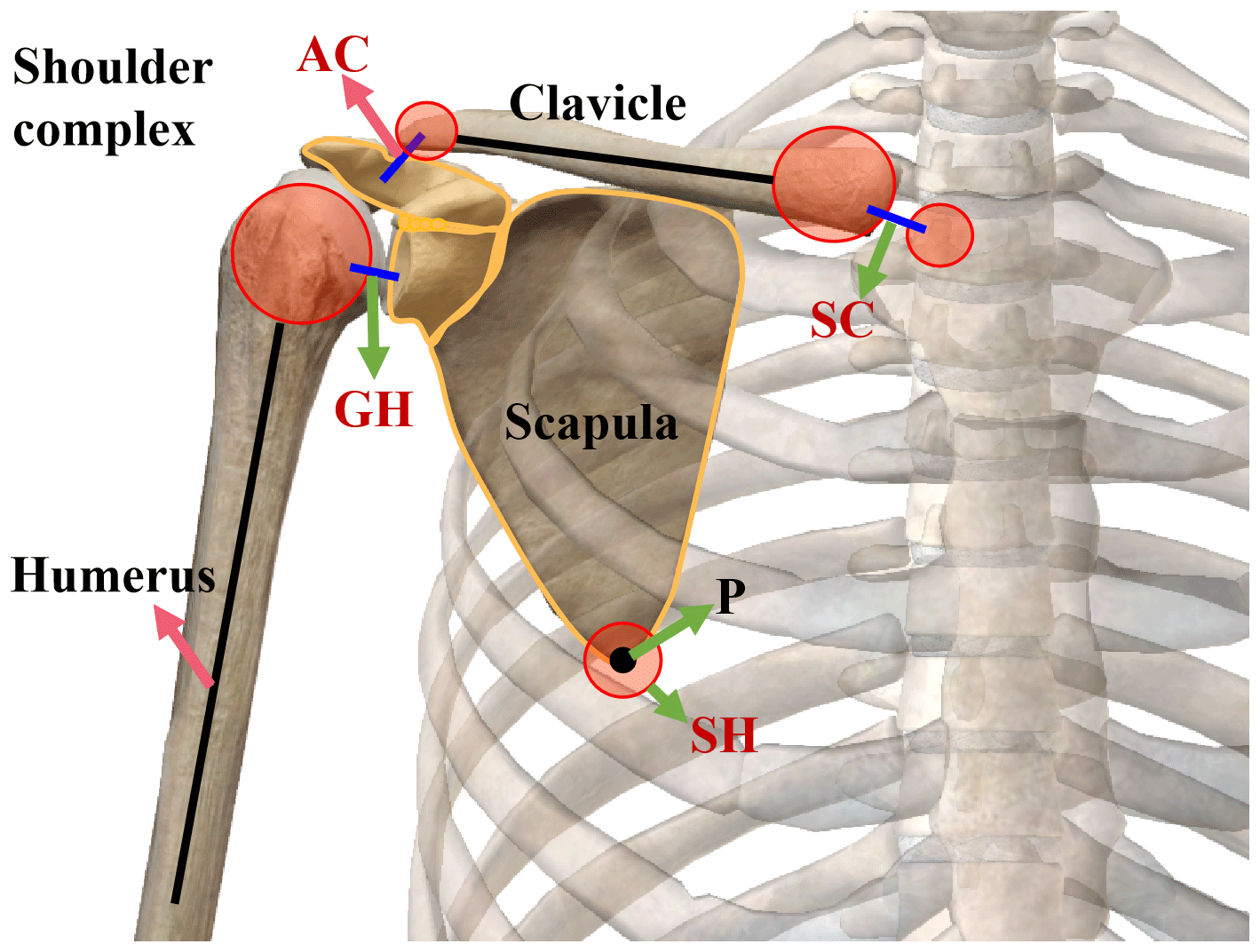
The design of the upper limb exoskeleton is generally based on the movement of the human arm. The number of DOF is defined according to the shoulder joint, elbow joint, and wrist joint as usual, which are 3 DOF for the shoulder joint (flexion/extension, abduction/adduction, and internal/external rotation), 2 DOF for the elbow joint (flexion/extension and pronation/supination), and 2 DOF for the wrist joint (radial/ulnar deviation and flexion/extension). Other existing models of exoskeletons for the human arm include, for instance, ETS-MARSE (Rahman et al., 2015), CADEN-7 (Perry et al., 2007; Perry and Rosen, 2006), and SUEFUL-7 (Gopura et al., 2009). In addition, there are also some researchers that decreased the number of DOF at the elbow joint and wrist joint, such as RETRAINER (Ambrosini et al., 2017), HAMEXO-I (Huang et al., 2014), and some other exoskeletons (Mahdavian et al., 2015; Wong and Mir-Nasiri, 2012; Wu et al., 2014), in order to simplify the design. The DOF at the shoulder joint are retained to ensure the moveability in these designs. However, these articulated exoskeletons still cannot stay in line with human movement. The main reason, as shown in Fig. 1, is that the shoulder abduction of 180∘ is added to the 60∘ scapulothoracic (SH) joint upward rotation and the 120∘ glenohumeral (GH) joint abduction. In addition, the 60∘ SH upward rotation is depicted as being the summation of the 25∘ of sternoclavicular (SC) joint elevation and the 35∘ of acromioclavicular (AC) joint upward rotation. The red arrow in Fig. 1 indicates the change in the axis of the GH joint when the shoulder joint is abducted from 0 to 180∘. It is the change in the rotation center of the shoulder complex during the movement that causes the misalignment between the exoskeleton and human arm (Neumann, 2013). Therefore, the shoulder joint is a compound joint, and its movement should consider the roles of the clavicle and the scapula in addition to the humerus.

Figure 1Rear view of the right shoulder complex (the shoulder abduction 180∘; Neumann, 2013).
There are a large number of researchers who have proposed the equivalent kinematic model of the upper limb to find the kinematic characteristics of human arm. Bertomeu-Motos et al. (2018) and Fang et al. (2019) simplified the human arm into a 7 DOF model, connected through two links, namely the upper arm and forearm. However, the model did not consider the contribution of the AC, SH, and SC joints. Eduardo et al. (2018) proposed a biomimetic kinematics model for upper extremity exoskeletons to simulate the contribution of the clavicle movement to the shoulder complex in the coronal plane. The proposed exoskeleton design based on the upper limb kinematic model shows a 17.1 % increase in the motion workspace on the coronal plane with the clavicle compared to non-clavicle designs. The kinematic characteristics in the sagittal plane and horizontal plane were not analyzed. Klopcar and Lenarcic (2006) researched kinematic shoulder complex characteristics on healthy subjects and proposed a model composed of an inner and outer shoulder joint. The inner shoulder joint has two rotations, with the center in the origin of the reference coordinate, and the outer has three rotations, with axes intersecting in the center of the GH joint. The advantage of the model is the inclusion of the shoulder girdle kinematics obtained as functions of the humeral elevation angle. Klopcar and Lenarcic (2005) reported an improved kinematic model of the human arm including the shoulder complex and elbow complex. The kinematic model is appropriate for computing and visualizing the human arm's reachable workspace. However, the kinematic model did not contain the wrist joint and simplified AC, SH, and SC joints into an universal joint and one slider, which ignored the motion characteristics of human arm too much, such as the scapula extension/retraction (Neumann, 2013). The kinematic model for workspace determination also did not contain the internal/external rotation of the elbow joint. In addition, Laitenberger et al. (2014) refined the upper limb model by means of a forearm closed-loop kinematic chain and personalized joint parameters to quantify kinematics and dynamics of the forearm joint. The wrist joint was simplified into a universal joint (Duprey et al., 2016). In order to understand the kinematic characteristics of the upper limb, the equivalent kinematic model should include not only the GH, elbow, and wrist joints but also the AC, SH, and SC joints.
The challenges of exoskeleton design include motion control and posture determination of its multiple DOF robotic components. In addition, the highly complex mechanical and redundant structures of human joints represent current research objects (Eduardo et al., 2018). The upper limb equivalent kinematic model is a common ground in these two fields, which can provide a reference for the structural design, posture determination, and motion trajectory of the upper limb exoskeleton. This key application promotes the further development of the upper extremity exoskeleton to provide more effective rehabilitation training and motion assistance for stroke patients. Various equivalent kinematic models of the upper limb have been proposed. However, most of the models simplify the DOF of human upper limbs and cannot fully describe the movement of upper limbs, and there are few studies on the application of these models in exoskeleton design. Therefore, the goal of this paper is to propose a new equivalent kinematic model for the human upper limb that will describe the movement characteristics of the human upper limbs as fully as possible and explain how the model can be used to evaluate and improve the design of upper limb exoskeleton rehabilitation robots.
The remainder of this paper is organized as follows. We present, in the next two sections, the proposed method for the equivalent kinematic model of human arm, kinematic analysis, motion space, and evaluation method. In Sect. 4, the results are presented. The discussion is conducted in Sect. 5, and we summarize and conclude this paper in Sect. 6.
2.1 Modeling
The shoulder complex contains four joints, namely the SC, AC, SH, and GH joints, as shown in Fig. 2. The SC joint is the most proximal joint of the shoulder complex. It serves as the base point for the entire upper limb and connects the upper limb to the axial skeleton. The SC joint has 3 DOF, and the primary movements are protraction and retraction, elevation and depression, and upward and downward rotation. The AC joint is a sliding or planar joint that provides maximum mobility between the scapula and the thorax. The SH joint has 3 DOF, including elevation, depression, extension, retraction, and rotation, as shown by the P point in Fig. 2. The GH joint is the most distal connection of the shoulder complex. The GH joint, together with the moving scapula, produces an extensive range of motion of the shoulder. It is a universal joint with 3 DOF, including flexion, extension, abduction, adduction, internal rotation, and external rotation, formed between the scapula and articular fossa of the humerus. The bones and joints of the shoulder complex are shown in Fig. 2, which simplifies the bones and joints into a suitable calculation model for easy analysis of the shoulder movements. Figure 3 is an equivalent kinematic model corresponding to the upper limb. The bones are simplified into links, and the point P is the end position of the scapula. The SC, SH, and GH joints are simplified into a spherical hinge with limited motion range. This model ignores the movement of the AC joint due to the small activity of the AC joint in activities of daily living (ADL).
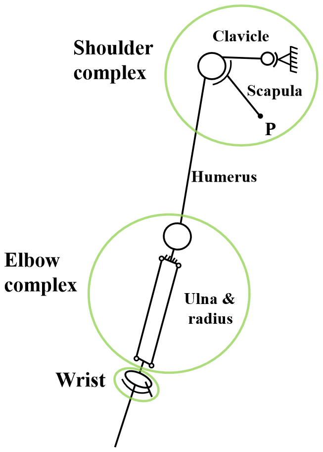
The elbow and forearm complex consists of three bones and four joints in Fig. 4. The connection of the elbow and forearm greatly increases the effective ROM of the hand. In Fig. 3, the elbow is simplified into a rotating joint. In addition, the radius and ulna are connected in the forearm through the proximal and distal radioulnar joints, so the equivalent kinematic model of the forearm is a four-bar linkage structure, and the fixed end is at the proximal end with the internal and external rotation of the forearm.
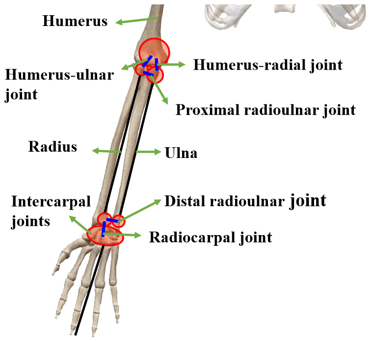
The wrist acts as a functional “gasket” between the forearm and the hand and consists of two major joints, i.e., the radiocarpal joint and the intercarpal joint, which allow the wrist to flex, extend, abduct, and adduct (see Fig. 4; Neumann, 2013). In Fig. 3, the wrist is simplified into a sphere pin pair. The wrist joint is the end position of the model, and the position of the hand can be obtained by studying the position of the wrist joint.
The equivalent kinematic model of the human upper limb has two end points, namely the wrist and the scapula. Its kinematics is divided into two chains, where the first chain is the chain of motion at the end wrist, which includes the sternum, the SC joint, clavicle, GH joint, humerus, elbow, forearm, and wrist. The second chain is the chain of motion at the end scapula, which includes the sternum, SC joint, clavicle, and SH joint.
2.2 Kinematic analysis
The motion of a rigid body consists of translation and rotation. The approaches of homogeneous coordinates and homogeneous transformation for kinematics analysis are adopted to describe translation and rotation. The homogeneous coordinate describes the spatial position, and the homogeneous transformation describes the transformation of the rigid body position and posture. The coordinate systems for the equivalent kinematic model of the human arm are shown in Figs. 5 and 6. The origin of the coordinate systems (Xi, Yi, and Zi) is set at the joints, where i = 0–6 represents the origin of the coordinate systems in the sternum, the SC, GH, elbow joints, center of rotation of the forearm, the wrist, and SH joints, respectively. The model has 13 DOF. They are 3 DOF for the SC joint, 3 DOF for the SH joint, 3 DOF for the GH joint, 2 DOF for the elbow joint, and 2 DOF for the wrist joint, respectively. In Fig. 6, ϕi, θi, and φi are the angles of pronation/external rotation, flexion/extension, and adduction/abduction, respectively. And the angles of internal rotation, extension, and adduction are positive values, and the angles of external rotation, flexion, and abduction are negative values. β is the inclination angle of the scapula, and the length parameters of the human upper limb are annotated in Fig. 6.
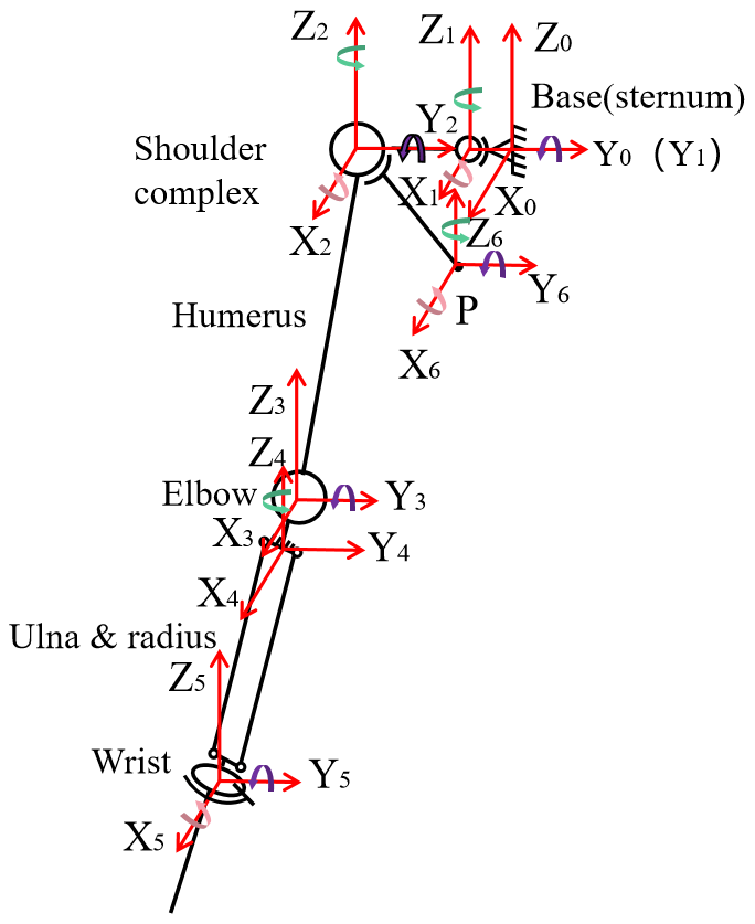
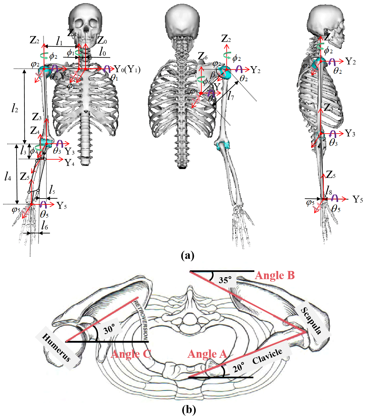
Figure 6Set the parameters of the model. (a) Front view, back view, and right side view of a human arm. (b) Top view of both shoulders in the anatomical position. Angle A shows that the direction of the clavicle is about 20∘ behind the front plane. Angle B shows that the cap is offset by approximately 35∘ in front of the front plane. Angle C shows that the humeral head is tilted back about 30∘ (Neumann, 2013).
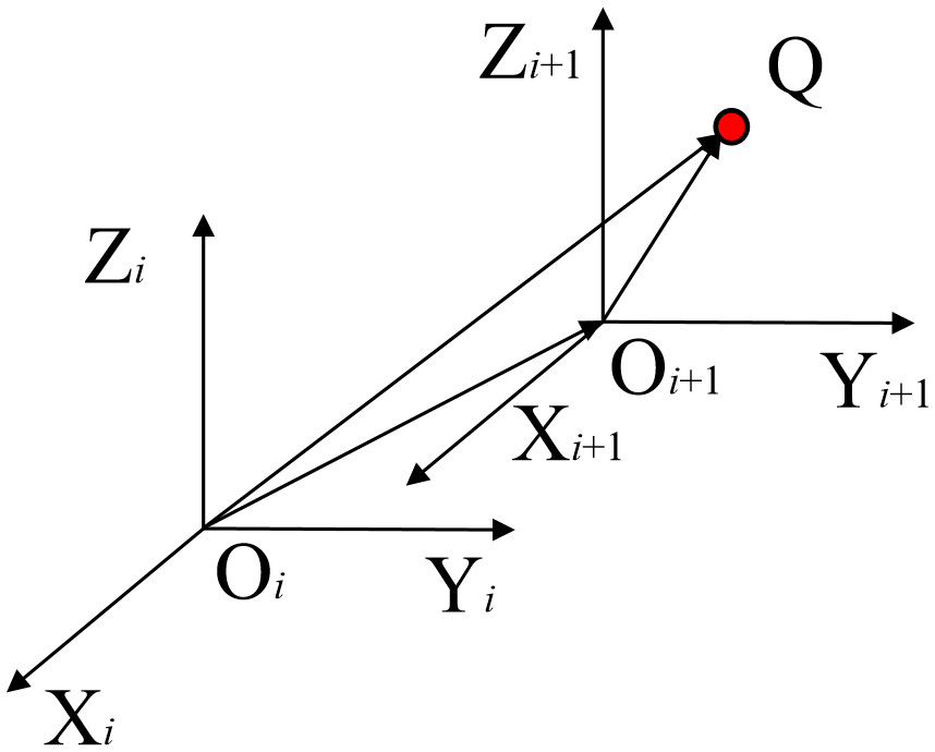
As shown in Fig. 7, coordinate transformation from (Xi, Yi, and Zi) to (Xi+1, Yi+1, and Zi+1) is given by the following:
where iRi+1 is the rotation matrix from (Xi, Yi, and Zi) to (Xi+1, Yi+1, Zi+1), and Q (px, py, and pz) is any point in the coordinates.
The homogeneous transformation matrix iAi+1 takes the following form:
In Fig. 6, we can obtain the homogeneous matrix of human arm at the end point according to Eqs. (1)–(3). In the following, where cos is C and sin is S:
0A5 describes the position and posture of the end effector of the first chain, and 0A6 describes the position and posture of the end effector of the second chain.
2.3 Motion space
In anatomy, the terms sagittal plane, coronal plane, and horizontal plane are used to describe the kinematics of human bones. In order to better analyze the movement of upper limb, we also projected the motion space into these three surfaces. These motion planes are described by placing people in anatomical locations. The sagittal plane is parallel to the sagittal suture of the skull. The coronal plane is parallel to the coronal joint of the skull. The horizontal plane is parallel to the ground, and the body is divided into upper and lower parts. This paper provides preliminary data and is a proof of concept for the new kinematic model and exoskeleton prototype (l0=20 mm, l1=222 mm, l2=320 mm, l3=65 mm, l4=251 mm, l5=28 mm, l6=65 mm, l7=151 mm, and l8=0). (pxj, pyj, and pzj) is the position coordinate of the end of the first chain, and (pxjsca, pyjsca, and pzjsca) is the position coordinate of the end of the second chain, where j = 1–3 represent the sagittal, coronal, and horizontal planes, respectively.
2.3.1 The motion space in the sagittal plane
The motion of the arm kinematic model is projected into the sagittal plane. The movement of the sagittal plane is mainly flexion/extension. The motion of the model is simplified as the extension and retraction of the SC joint, flexion/extension of the GH joint, flexion/extension of the elbow, and forward/backward inclination of the SC joint, with θ1 = −30 to 30∘, θ2 = 0 to 150∘, and θ3 = 0 to 150∘.
The kinematic equation of the first chain in the sagittal plane is obtained as follows:
The motion space of the first chain in the sagittal plane is shown in Fig. 8a.
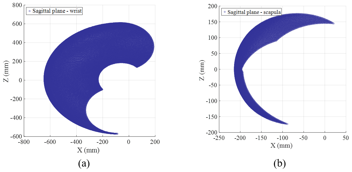
Figure 8The motion space in the sagittal plane. (a) The motion space of the wrist in the sagittal plane. (b) The motion space of the scapula in the sagittal plane.
The kinematic equation of the second chain in the sagittal plane is obtained as follows:
The motion space of the second chain in the sagittal plane is shown in Fig. 8b.
2.3.2 The motion space in the coronal plane
The motion of the arm kinematic model is projected into the coronal plane. The movement of the coronal plane is mainly adduction/abduction. The motion of the model is simplified as the elevation/depression of the SC joint, adduction/abduction of the GH joint, and elevation/depression of the SH joint, with φ1 = −30 to 30∘ and φ2 = −40 to 180∘.
The kinematic equation of the first chain in the coronal plane is obtained as follows:
The motion space of the first chain in the coronal plane is shown in Fig. 9a.
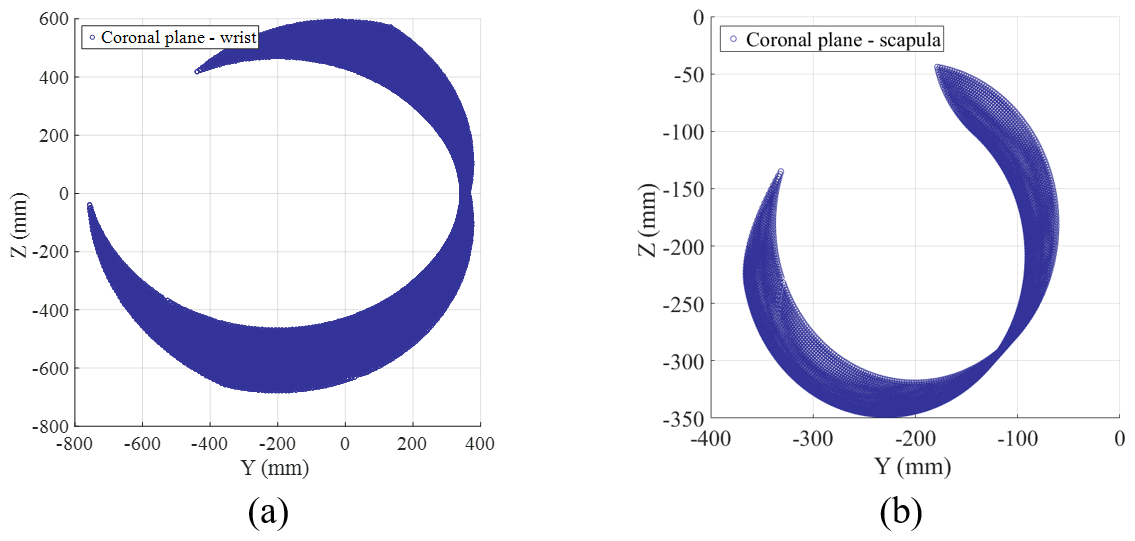
Figure 9The motion space in the coronal plane. (a) The motion space of the wrist in the horizontal plane. (b) The motion space of the scapula in the horizontal plane.
The kinematic equation of the second chain in the coronal plane is obtained as follows:
The motion space of the second chain in the coronal plane is shown in Fig. 9b.
2.3.3 The motion space in the horizontal plane
The motion of the arm kinematic model is projected into the horizontal plane. The movement of the horizontal plane is mainly rotation. The motion of the model is simplified as the rotation of the SC joint, internal/external rotation of the GH joint, internal/external rotation of the forearm, and the inward/outward inclination of the SH, with ϕ1 = −20 to 20∘ and ϕ2 = −80 to 80∘.
The kinematic equation of the end effector of the first chain in the horizontal plane is obtained as follows:
The motion space of the first chain in the horizontal plane is shown in Fig. 10a.
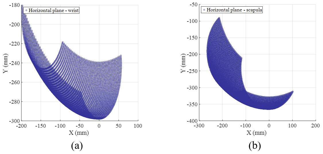
Figure 10The motion space in the horizontal plane. (a) The motion space of the wrist in the horizontal plane. (b) The motion space of the scapula in the horizontal plane.
The kinematic equation of the second chain in the horizontal plane is obtained as follows:
The motion space of the second chain in the horizontal plane is shown in Fig. 10b.
3.1 Evaluation method
It is a key problem that the existing upper limb exoskeletons cannot stay in line with the corresponding human arm during exercise. Therefore, we propose an evaluation method of the upper limb exoskeletons based on the kinematic model of the human arm. Through the evaluation of an exoskeleton, we can find the misalignment that happened between exoskeletons with the human arm.
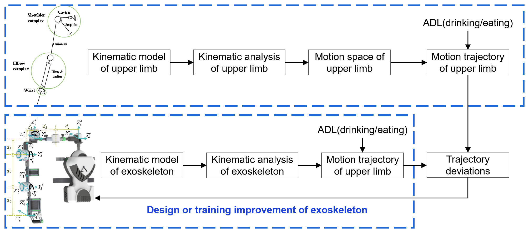
The schematic representation of the evaluation method is shown in Fig. 11, and the specific steps of the evaluation method for an upper limb exoskeleton rehabilitation robot are as follows:
-
Step 1. It is necessary to obtain the kinematic equation of the exoskeleton, and the motion trajectory of the exoskeleton can be obtained by adding interpolation to the kinematic equation.
-
Step 2. The joint angles of the exoskeleton can be obtained by the inverse kinematic equation. Next, the joint angles are substituted into the kinematic equation of human arm, and we can obtain the trajectories of the exoskeleton and the human arm for the same movement.
-
Step 3. It is important to compare the deviation of the trajectories of the exoskeleton and the human arm. If there is a deviation between the trajectories, we can find the position of the deviation and analyze the causes.
-
Step 4. Through the above analysis of the deviation, this paper proposes the requirements for the design of an upper limb exoskeleton and the rehabilitation trajectory planning for upper limb rehabilitation robots.
The trajectory of the human upper limb can be obtained quickly and accurately using the equivalent kinematic model proposed in this paper. By comparing the trajectory deviation of the human arm and exoskeleton robot, the restricted positions of the exoskeleton on the human body can be found. If the mechanical structure of the exoskeleton is improved in the restricted position, the movement restriction of the exoskeleton to the human can be reduced.
3.2 Kinematic analysis of an upper limb exoskeleton robot based on wheelchair
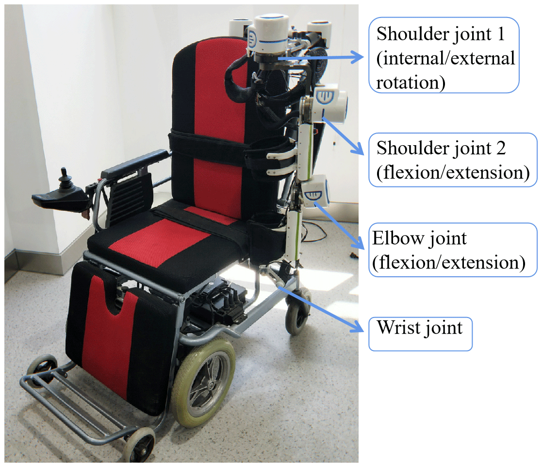
In order to help patients with hemiplegia or spinal cord injury to restore impaired or lost upper limb functionalities efficiently, Meng et al. (2019) designed an upper limb exoskeleton robot based on a wheelchair, which not only transfers the weight of the affected limb and exoskeleton to the wheelchair, but also integrates rehabilitation training and assisting in ADL functions (Meng et al., 2019). The prototype of an upper limb exoskeleton robot based on a wheelchair has 3 active DOF, and its primary movements are internal/external rotation and flexion/extension of the shoulder joint and flexion/extension of the elbow joint. The exoskeleton arm length can be adjusted according to different users, as shown in Fig. 12. Next, we will evaluate the assisting or training effect of this exoskeleton.
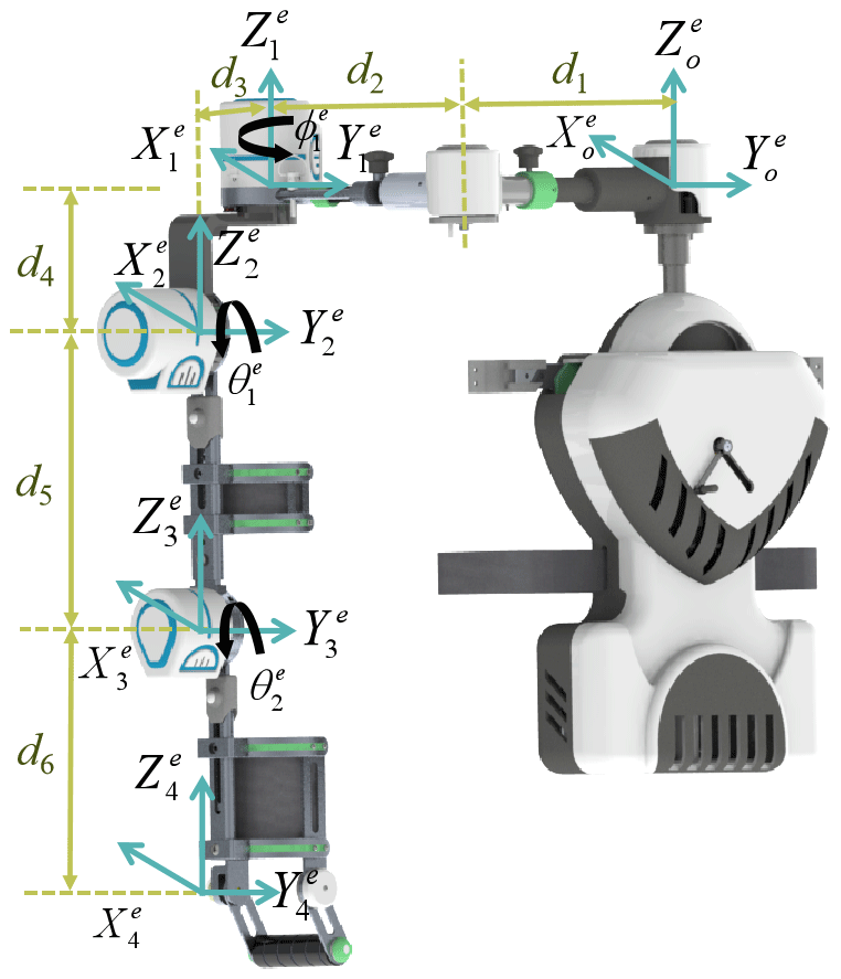
The coordinate systems used in the prototype are established at each rotation center in Fig. 13. The starting coordinate system is set at the starting point of the exoskeleton. The coordinate systems and are set at the shoulder joint. The coordinate systems and are set at the elbow and wrist joints, respectively.
(, , and ) is the position coordinate of the end of the exoskeleton. and are the angles of internal rotation and flexion of the shoulder of the exoskeleton. is the angle of flexion of the elbow of the exoskeleton. Where the distance between each coordinate is d1 = 180–300 mm, d2 = 200–400 mm, d3 = 112 mm, d4 = 130 mm, d5 = 250–350 mm, and d6 = 200–300 mm.
The forward kinematic equations of the exoskeleton robot are described as follows:
Equation (11) describes the position of the wrist of the exoskeleton in a three-dimensional space. The inverse kinematic equations of the exoskeleton robot are described as follows:
Equation (12) describes the angles of the shoulder and elbow joints of the exoskeleton. The joints angles of the exoskeleton can be resolved by the inverse kinematic equation by giving the position in the motion space.
4.1 Trajectory of the exoskeleton
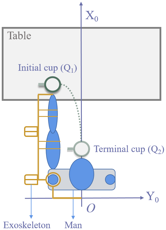
Drinking water trajectory planning is chosen in this paper as an example. In general, the upper limb motion for drinking can be divided into two motions; the first motion is taking the cup, and the second motion is putting the cup to the mouth. As shown in Fig. 14, the initial coordinate of the cup is Q1 (772, −399, and 319), the terminal coordinate of the cup is Q2 (510, −73, and −24), the initial angular velocities of three joints are 0, each joint is moving at uniform motion during the drinking, and time for each step is 3 s.
The joint angles of the exoskeleton taking the cup can be obtained with the cubic polynomial as follows:
The joint angles of the exoskeleton holding the cup to the mouth can be obtained by the cubic polynomial as follows:
By substituting Eqs. (13) and (14) into Eq. (1), we can obtain the drinking trajectory of the exoskeleton.
4.2 Trajectory of human arm
The initial coordinate of the cup is Q1 (772, −399, and 319) in the exoskeleton coordinate system, and the joint angles of the exoskeleton are , ∘, and ∘. Therefore, , ∘, ∘. The difference between the origin of the exoskeleton coordinate system and the origin of the human coordinate system is = (356, −25.3, −130). The first drinking trajectory of the upper limb can be obtained by the cubic polynomial as follows:
The initial coordinate of the cup is Q2 (510, −73, and −24) in the exoskeleton coordinate system, and the joint angles of the exoskeleton are ∘, ∘, and ∘. Therefore, ∘, and ∘. The external rotation of the exoskeleton is the adduction and abduction in the human upper limb, so . The known is . The kinematics equation of the first chain in the coronal plane can be obtained with ∘ and ∘. The second drinking trajectory of the upper limb can be obtained from the cubic polynomial as follows:
4.3 Comparison of the two trajectories
The drinking trajectories of the exoskeleton and human arm are shown in Fig. 15. The trajectories of the exoskeleton and human arm show the same movement trend, but there are some deviations.
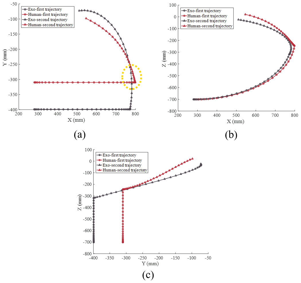
In Fig. 15a, the second human trajectory intersects with the second exo trajectory trajectory. In Fig. 15b and c, the Z value of the second human trajectory is larger than that of the second exo trajectory, which can cause the motion space of upper limb exoskeleton not to encompass the motion space of the human arm. Therefore, the drinking trajectories of the exoskeleton deviate from the drinking trajectories of the human body.
4.4 Comparison of the two trajectories
Figures 15 and 16 show the following:
- A.
The Z value of the human–second trajectory is larger than that of the exo–second trajectory in Fig. 15b and c. This shows that the movement of the human arm is limited by the exoskeleton when drinking water. Therefore, the rehabilitation training is not as effective as expected because of the limitation of the exoskeleton.
- B.
As shown in Fig. 16, the trajectory of the human shoulder joint is completely inconsistent with that of the exoskeleton shoulder joint, due to the different DOF of their shoulder joints. The shoulder of the exoskeleton has only 2 DOF and does not fully simulate the shoulder complex. In Fig. 13, the elbow joint of the exoskeleton is fixed by two straps to the upper arm and the forearm. Therefore, the trajectory's deviation between the human arm and the exoskeleton is caused by the inconsistency of their shoulder joints.
Based on the evaluation results of the exoskeleton, this paper presents a method to improve drinking training. According to what is mentioned above, it is known that the reason for the inconsistency is the limitation of the shoulder joint. Hence, we can increase the flexion angle of the exoskeleton shoulder to reduce the inconsistency, and the joint angles of the human do not change. In the first trajectory, adds 12∘. In the second trajectory, adds 9∘. From Figs. 14b to 17b, the intersection of trajectories is reduced to a series of points. In Fig. 17a, the new trajectories improve the compliance between the exoskeleton and human. Figure 17c shows that the Z value of the exoskeleton trajectory is larger than that of the human.
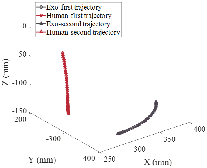
Figure 16The trajectory of the shoulder joint of the exoskeleton and the upper limb when drinking water.
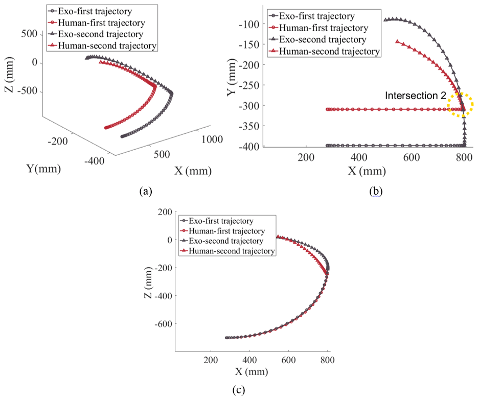
Figure 17The improved drinking trajectories of the exoskeleton and human. (a) Three-dimensional view. (b) Horizontal plane view. (c) Sagittal plane view.
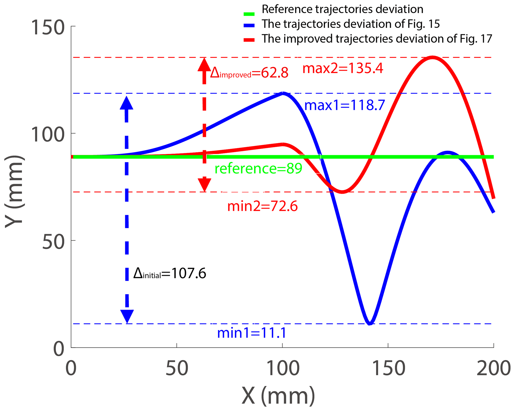
The comparison of trajectory deviations in Figs. 15 and 17 is shown in Fig. 18. The reference trajectory's deviation is the deviation between the end effector of the exoskeleton and the end effector of human at the initial time without any movement, and it is equal to 89 mm. In Fig. 18, the term “initial” denotes the interval between the maximum and minimum values of the trajectory's deviation range in Fig. 15, and it is equal to 107.6 mm. The term “improved” denotes the interval between the maximum and minimum values of the improved trajectory's deviation range in Fig. 17, and it is equal to 62.8 mm. δ is the improvement rate of the trajectory's deviation, and it is equal to 41.64 %, following as Eq. (17), which can improve the compliance and comfort between the human body with the exoskeleton. Therefore, the value of δ is very important for improving the compliance and comfort of the exoskeleton. The reason why it is difficult for δ (41.64 %) to reach a higher value is due to the mechanism design of the exoskeleton robot. The main reason is that the kinematic characteristics of the clavicle and scapula were ignored in the design of the exoskeleton, causing the inconsistency between the human and the exoskeleton. The improvement of the mechanism design of the exoskeleton will be introduced in the next work.
From the abovementioned trajectory deviation improvement scheme, we find the following:
- A.
The movement angle of a human arm is smaller than that of the exoskeleton due to the trajectory deterioration. When a therapist makes a personalized rehabilitation treatment plan for a patient, the therapist can choose to appropriately increase movement angle of the exoskeleton to make the patient's training closer to the plan to improve the treatment effect.
- B.
In addition, a new idea is proposed for the structural improvement of the exoskeleton to increase the user's motion space. We can choose to add kinematic redundancy in the human–exoskeleton interaction position (arm binding) to increase the user's movable space.
Upper limb exoskeleton rehabilitation robots have become more popular. Various upper limb rehabilitation robots have appeared, and how to evaluate and improve the design of upper limb rehabilitation robots has also become a research hot spot. One of the critical technologies of upper limb exoskeletons is human–exoskeleton interaction. Misalignment compensation for full human–exoskeleton kinematic compatibility will reduce the effect of rehabilitation training, limit arm movement, and cause discomfort or secondary injury (Lo and Xie, 2012; Rocon et al., 2007; Schiele and Helm, 2006; Cao et al., 2020). There are three main methods of misalignment compensation, including manual alignment, compliant elements, and adding kinematic redundancy (Näf et al., 2019). Different misalignment compensation methods have different effects, so the effects need to be evaluated. This paper proposes an exoskeleton evaluation method, which uses the equivalent kinematics model of the human body for effect evaluation. The equivalent kinematics model includes not only the SC, SH, and GH but also the elbow and wrist joints. Meanwhile, this paper analyzes the motion space according to the normal range of motion of joints for building the workspace of the proposed model. Then, the trajectory planning for an upper limb exoskeleton is evaluated and improved based on the proposed model. The evaluation results show that there were obvious differences between the exoskeleton and human upper limb. The deviation between human body and the exoskeleton of the improved trajectory is decreased to 41.64 %. Therefore, it can be concluded that, if we want to reduce the restriction on human movement, we can increase the movement angle of the exoskeleton by adding kinematic redundancy in the exoskeleton shoulder joint.
Bertomeu-Motos et al. (2018) and Fang et al. (2019) simplified the human arm into a 7 DOF arm model, which only includes the GH, elbow joint, and wrist joint. Rosen et al. (2005) proposed a design of a 7 DOF upper-limb-powered exoskeleton (shoulder – 3 DOF; elbow – 2 DOF; wrist – 3 DOF); it is the same as the model of Bertomeu-Motos et al. (2018) and Fang et al. (2019). Klopcar and Lenarcic (2006), Carignan et al. (2005), and Rosen et al. (2005) emphasized the contribution of the clavicle and scapula to upper limb movement. However, most of these equivalent models simplify excessive upper limb movement, and it is difficult to completely describe the upper limb movement. Such models are more appropriate for providing assistance in the design of an exoskeleton rather than evaluating the effects of upper limb rehabilitation robots. This paper proposes a new, 13 DOF equivalent kinematic model that can more accurately describe the movement of the human upper limbs. The shoulders, including the shoulder complex model, were able to contract up to 35 % or 38 % in maximal unilateral or bilateral humeral elevation, respectively (Klopcar and Lenarcic, 2006). This is consistent with the results of this paper; the trajectory's deviation between the human and exoskeleton is caused by the inconsistency of the shoulder joints in this paper. Furthermore, an assessment of a clavicle model showed an equally enhanced performance. Compared with non-clavicle designs, the proposed design showed a 17.1 % increase in the anatomic workspace usage by the inclusion of the clavicle contribution to the coronal plane (Eduardo et al., 2018). Therefore, the shoulder complex model should be included in the design of the upper limb exoskeleton. The research in this paper also has some shortcomings. For example, the ROM of SH and SC is obtained through the related literature or books, and there may be measurement errors and differences from person to person. There is also a certain error in the measurement of upper limb length. In later studies, we will continue to improve the upper limb equivalent kinematics model of this study. Additional testing would provide the basis for an additional paper once completed.
This paper proposes a new 13 DOF equivalent kinematic model for the human upper limb, including the sternoclavicular (SC) joint, scapulothoracic (SH) joint, glenohumeral (GH) joint, elbow joint, and wrist joint. The model fully considers the movement characteristics of human upper limbs in anatomy. The proposed model can be utilized to analyze the human upper limb workspace and joint motion. Furthermore, the intersection of the trajectories of the human upper limb model and exoskeleton will be found by comparing their trajectories of the same movement. Changes to the design of the exoskeleton are proposed to improve on trajectory deviation that is experienced. Therefore, the upper limb equivalent kinematic model proposed in this paper can be applied to upper limb kinematics analysis, workspace, and trajectory planning. Based on the trajectory of the model, the design of the upper limb exoskeleton is evaluated to improve the human–exoskeleton interaction, reduce the restriction of the exoskeleton on the human body, and improve the training and assisting effects of the exoskeleton. In future work, we will provide more testing results of the exoskeleton and continue to study more evaluation indicators and improvement suggestions for upper limb exoskeleton rehabilitation robots and strive to improve the rehabilitation effects of patients.
All data included in this study are available upon request from the corresponding author.
QX conceived the idea, developed the method, performed experiments and simulations, and wrote the majority of the paper. QM and HY supervised and structured the paper. QZ edited the paper, and ZS corrected the paper.
The authors declare that they have no conflict of interest.
The authors would like to thank the National Natural Science Foundation of China (grant no. 61803265) and Science and Technology Commission of Shanghai Municipality, China (grant no. 20S31905400), for their support.
This research has been supported by the National Natural Science Foundation of China (grant no. 61803265) and the Science and Technology Commission of Shanghai Municipality (grant no. 20S31905400).
This paper was edited by Mohamed Amine Laribi and reviewed by two anonymous referees.
Ambrosini, E., Ferrante S., Zajc, J., Bulgheroni, M., Baccinelli, W., D'Amico, E., Schauer, T., Wiesener, C., Russold, M., and Gfoehler, M.: The combined action of a passive exoskeleton and an EMG-controlled neuroprosthesis for upper limb stroke rehabilitation: First results of the RETRAINER project, 56–61, https://doi.org/10.1109/ICORR.2017.8009221, IEEE Int Conf Rehabil Robot, London, UK, 2017.
Bertomeu-Motos A., Blanco A., Badesa F. J., Barios J. A., Zollo L., and Garcia-Aracil N.: Human arm joints reconstruction algorithm in rehabilitation therapies assisted by end-effector robotic devices, J. Neuroeng. Rehabil., 15, 10, https://doi.org/10.1186/s12984-018-0348-0, 2018.
Côté-Allard, U., Fall, C. L., Drouin A., Campeau-Lecours, A., Gosselin, C., Glette, K., Laviolette, F., and Gosselin, B.: Deep Learning for Electromyographic Hand Gesture Signal Classification Using Transfer Learning, IEEE Trans. Neural. Syst. Rehabil. Eng., 15, 10, https://doi.org/10.1186/s12984-018-0348-0, 2018.
Cao, W., Chen, C., Hu, H., Fang, K., and Wu, X.: Effect of Hip Assistance Modes on Metabolic Cost of Walking With a Soft Exoskeleton, IEEE T. Autom. Sci. Eng., 18, 426–436, https://doi.org/10.1109/TASE.2020.3027748, 2020.
Carignan, C., Liszka, M., and Roderick, S.: Design of an arm exoskeleton with scapula motion for shoulder rehabilitation, Int. Conf. Adv. Robot., 2005, 524–531, https://doi.org/10.1109/ICAR.2005.1507459, 2005.
Duprey, S., Naaim, A., Moissenet, F., Begon, M. L., and Chèze, L.: Kinematic models of the upper limb joints for multibody kinematics optimisation: An overview, J. Biomech., 62, 87–94, https://doi.org/10.1016/j.jbiomech.2016.12.005, 2016.
Eduardo P., Ricardo R., Salvador L. M., and Ernesto, R. L.: Vision System-Based Design and Assessment of a Novel Shoulder Joint Mechanism for an Enhanced Workspace Upper Limb Exoskeleton, Appl. Bionics Biomech., 2018, 1–14, https://doi.org/10.1155/2018/6019381, 2018.
Esmaeili, M., Gamage, K., Tan, E., and Campolo, D.: Ergonomic considerations for anthropomorphic wrist exoskeletons: A simulation study on the effects of joint misalignment, IEEE/RSJ Int. C. Int. Robot., 2011, 4905–4910, https://doi.org/10.1109/IROS.2011.6095136, 2011.
Fang, C., Ajoudani, A., Bicchi, A., and Tsagarakis, N. G.: A Real-Time Identification and Tracking Method for the Musculoskeletal Model of Human Arm, 2018 IEEE Sys. Man Cybern., 2018, 3472–3479, https://doi.org/10.1109/SMC.2018.00588, 2019.
Gopura, R., Kiguchi, K., and Bandara, D.: A brief review on upper extremity robotic exoskeleton systems, 6th IEEE International Conference on Industrial and Information Systems (ICIIS), 2011, 346–351, https://doi.org/10.1109/SMC.2018.00588, 2011.
Gopura, R. A. R. C., Kiguchi, K., and Li, Y.: SUEFUL-7: A 7DOF upper-limb exoskeleton robot with muscle-model-oriented EMG-based control, IEEE/RSJ International Conference on Intelligent Robots & Systems, 2009, 1126–1131, https://doi.org/10.1109/IROS.2009.5353935, 2009.
Huang, J.-B., Hong, J.-C., Young, K.-Y., and Ko, C.-H.: Development of upper-limb exoskeleton simulator for passive rehabilitation, 2014 CACS International Automatic Control Conference (CACS 2014), 335–339, 2014.
Jarrasse, N., Tagliabue, M., Robertson, J. V. G., Maiza, A., Crocher, V., Roby-Brami, A., and Morel, G.: A methodology to quantify alterations in human upper limb movement during co-manipulation with an exoskeleton, IEEE Trans. Neural Syst. Rehabil. Eng., 18, 389–397, https://doi.org/10.1109/TNSRE.2010.2056388, 2010.
Klopcar, N. and Lenarcic, J.: Kinematic Model for Determination of Human Arm Reachable Workspace, Meccanica, 40, 203–219, https://doi.org/10.1007/s11012-005-3067-0, 2005.
Klopcar, N. and Lenarcic, J.: Bilateral and unilateral shoulder girdle kinematics during humeral elevation, Clin. Biomech., 21, S20–26, https://doi.org/10.1016/j.clinbiomech.2005.09.009, 2006.
Laitenberger, M., Raison, M., Périé, D., and Begon, M.: Refinement of the upper limb joint kinematics and dynamics using a subject-specific closed-loop forearm model, Multibody Syst. Dyn., 33, 1–26, https://doi.org/10.1007/s11044-014-9421-z, 2014.
Lo, H. S. and Xie, S. Q.: Exoskeleton robots for upper-limb rehabilitation: State of the art and future prospects, Med. Eng. Phys., 34, 261–268, https://doi.org/10.1016/j.medengphy.2011.10.004, 2012.
Maciejasz, P., Eschweiler, J. R., Gerlach-Hahn, K., Jansen-Troy, A., and Leonhardt, S.: A survey on robotic devices for upper limb rehabilitation, J. Neuroeng. Rehabil., 11, 1–29, https://doi.org/10.1186/1743-0003-11-3, 2014.
Mahdavian, M., Toudeshki, A. G., and Yousefi-Koma, A.: Design and Fabrication of a 3DoF Upper Limb Exoskeleton, ICROM 2015 IEEE conference, 2015.
Meng, Q., Xie, Q., and Yu, H.: Upper-Limb Rehabilitation Robot: State of the Art and Existing Problems, Proceedings of the 12th International Convention on Rehabilitation Engineering and Assistive Technology, 155–158, 2018.
Meng, Q., Xie, Q., Shao, H., Cao, W., Wang, F., Wang, L., Yu, H., and Li, S.: Pilot Study of a Powered Exoskeleton for Upper Limb Rehabilitation Based on the Wheelchair, Biomed. Res. Int., 2019, 9627438, https://doi.org/10.1155/2019/9627438, 2019.
Näf, M., Junius, K., Rossini, M., Rodriguez-Guerrero, C., Vanderborght, B., and Lefeber, D.: Misalignment compensation as a way to ensure full human-exoskeleton kinematic compatibility: state of the art and evaluation, Appl. Mech. Rev., 70, 050802, https://doi.org/10.1115/1.4042523, 2019.
Neumann, D. A.: Kinesiology of the musculoskeletal system-e-book: foundations for rehabilitation, Elsevier Health Sciences, 2013.
Perry, J. C. and Rosen, J.: Design of a 7 Degree-of-Freedom Upper-Limb Powered Exoskeleton, IEEE/RAS-EMBS International Conference on Biomedical Robotics & Biomechatronics, 2006, 805–810, https://doi.org/10.1109/BIOROB.2006.1639189, 2006.
Perry, J. C., Rosen, J., and Burns, S.: UpperLimb Powered Exoskeleton Design, IEEE-ASME T. Mech., 12, 408–417, https://doi.org/10.1109/TMECH.2007.901934, 2007.
Rahman, M. H., Rahman, M. J., Cristobal, O. L., Saad, M., Kenne, J. P., and Archambault, P. S.: Development of a whole arm wearable robotic exoskeleton for rehabilitation and to assist upper limb movements, Robotica, 33, 19–39, https://doi.org/10.1017/S0263574714000034, 2015.
Rocon, E., Belda-Lois, J., Ruiz, A., Manto, M., Moreno, J. C., and Pons, J. L.: Design and validation of a rehabilitation robotic exoskeleton for tremor assessment and suppression, IEEE Trans. Neural. Syst. Rehabil. Eng., 15, 367–378, https://doi.org/10.1109/TNSRE.2007.903917, 2007.
Rosen, J., Perry, J. C., Manning, N., Burns, S., and Hannaford, B.: The human arm kinematics and dynamics during daily activities – toward a 7 DOF upper limb powered exoskeleton, International Conference on Advanced Robotics, 2005, 532–539, https://doi.org/10.1109/ICAR.2005.1507460, 2005.
Schiele, A. and Helm, F. C. T. V. D.: Kinematic Design to Improve Ergonomics in Human Machine Interaction, IEEE Trans. Neural. Syst. Rehabil. Eng., 14, 456, https://doi.org/10.1109/TNSRE.2006.881565, 2006.
Wong, J. J. S. and Mir-Nasiri, N.: Design and Development of Human-Machine Interactive-Force Controlled Powered Upper-Limb Exoskeleton for Human Augmentation and Physical Rehabilitation, IEEE EMBS Conf on Biomedical Engineering & Sciences, 2012, 465–470, https://doi.org/10.1109/IECBES.2012.6498089, 2012.
Wu, Q., Wang, X., Du, F., and Xu, J.: Development and control of a Bowden-cable actuated exoskeleton for upper-limb rehabilitation, 2014 IEEE International Symposium on Robotic and Sensors Environments (ROSE) Proceedings, 2014, 7–12, https://doi.org/10.1109/ROSE.2014.6952975, 2014.
Zhang, L., Li, J., Su, P., Song, Y., Dong, M., and Cao, Q.: Improvement of human-machine compatibility of upper-limb rehabilitation exoskeleton using passive joints, Robotics and Autonomous Systems, 112, 22–31, https://doi.org/10.1016/j.robot.2018.10.012, 2018.