the Creative Commons Attribution 4.0 License.
the Creative Commons Attribution 4.0 License.
 | 10 Jun 2021
Research on forming technology of rotary forging with double symmetry rolls of large diameter : thickness ratio discs
Rong Fei Ma
Chun Dong Zhu
Yu Fan Gao
Zi Hao Wei
Rotary forging with double symmetry rolls (DSRs) is a new metal plastic forming technology developed on the basis of conventional rotary forging with a single roll, which uses a pair of symmetrical cone rolls to realize continuous local pressure plastic deformation of the workpiece. Large-diameter, thin discs are a key component in nuclear power, aerospace, deep-sea exploration, and other fields. At present, the forming process of large-diameter discs mainly includes welding and multiple local upsetting, but these processes exhibit many defects and can not meet the requirements of industry. In this paper, a large diameter : thickness ratio disc is integrally formed by rotary forging with DSRs. Using theoretical calculation and finite element simulation methods, the stable rolling conditions and calculation formulas of force and power parameters of rotary forging with DSRs of a large diameter : thickness ratio disc are derived. Based on the reliable three-dimensional rigid-plastic finite element model, the plastic deformation characteristics of rotary forging with DSRs of discs are studied, the reliability of the stable rolling conditions and the calculation formulas of force and power parameters are verified, and the defects and causes of unstable rolling conditions are analysed. An experiment was carried out on a rotary forging press developed with double symmetry rolls, and the experimental results are in good agreement with simulation results, which demonstrated that rotary forging with DSRs is a reliable technology for forming large diameter : thickness ratio discs. The results of this research are helpful to promote the further development of rotary forging with DSRs.
- Article
(3680 KB) - Full-text XML
- BibTeX
- EndNote


With the development of modern industrial technology, large integral disc parts are more widely used in industrial fields and have important applications in deep-sea exploration, nuclear energy, military industry, aerospace, and other fields. The cylindrical shell of a large hydrogenation reactor and a large spherical tank for deep-sea exploration are both produced by the forging process of large-diameter discs. An integral disc with a diameter of more than 8 m is required for the head plate of the nuclear reactor high-pressure vessels. The spaceflight fuel tank needs a circular plate with a diameter of 4 to 5 m and a height of 0.008 m. At present, the main forming processes of large-diameter discs are welding, plate cutting, and multiple local upsetting of the plate. When the large-diameter disc is formed by welding, more forming defects will occur. When the large-diameter disc is formed by a cutting plate, the machining is large, and the material utilization rate is low. When the large-diameter disc is formed by multiple local upsetting of the plate, it requires a large forging strike force and high-tonnage equipment, and the thickness error of the disc formed is large. The large-diameter discs produced by these forming processes cannot meet higher safety grades and cannot meet the needs of nuclear power, aerospace, and military industry for large-diameter integrally formed discs.
Rotary forging is an innovative metal plastic forming process which is widely used in manufacturing discs, rings, and gears (Yuan et al., 1999; Sheu et al., 2008; Zhu et al., 2011), and it has many advantages of a low forging pressure, a high machining accuracy, and a low level of noise and vibration. Owing to its inherent advantages, many scholars have studied rotary forging. Zhang (1984) studied the force and power parameters in the rolling process and derived the calculation formula of the force and power parameters. Canta et al. (1998) carried out rotary forming with lead and steel materials and obtained the energy distribution during the rotary forming processes. Choi et al. (1997) analysed the rotary forging process, studied the velocity field, and determined the upper-bound force by minimizing the total power consumption. Zhou et al. (1992a, b) studied the metal flow laws and forming defects in the process of rotary forging of the cylindrical workpiece, which provided a reference for die design. Jin et al. (2018) put forward a process optimization method for cold orbital forging of components with a deep and narrow groove, analysed the cold orbital forging process under three metal flow modes, and revealed defect mechanisms such as underfilling and folding. Jin et al. (2016) proposed a new sheet blank rotary forging process for thickening the rims of disc-like sheet blanks and studied the effects of the main defects and process parameters on formation. Zhuang et al. (2016) studied the cold orbital forging technology of spur bevel gears and analysed the influence of process parameters on the final step. Loyda et al. (2018) studied the influence of the rotary forging process on the microstructure behaviour of nickel-based superalloys. Pérez et al. (2017) analysed the microstructure and texture evolution of high-strength materials during the cold rotary forging process. Han et al. (2009, 2014) studied the difference of metal flow between cold rotary forging and conventional forging of the cylindrical workpiece and proposed a method of forming non-rotary gear parts by cold rotary forging. Han et al. (2016) proposed an innovative cold orbital forging method for manufacturing gear racks and conducted the accurate design of the die to ensure the forming accuracy of the gear rack. Liu et al. (2019, 2020) analysed the influence of process parameters of rotary forging on formation, defects, and preventive measures. For research on the formation of discs and rings, Wang et al. (1999, 2005) studied velocity fields and stress–strain fields of the ring workpiece in the rotary forging process and revealed the deformation mechanism of rotary forging of the ring workpiece. Hua et al. (2009) and Han and Hua (2011) studied the plastic deformation mechanism of cold rotary forging of cylindrical parts, analysed the effect laws of the feed rate of the lower die, rotational speed, and inclination angle of the upper die on metal flow and predicted the wear of dies. Liu et al. (2000, 2004) studied the forming process of rotary forging with a single roll of the cylindrical workpiece with a 20:1 height : diameter ratio, analysed the causes of the mushroom shape of the workpiece, and studied the deformation mechanism of centre-thinning of rotary forging of discs. Oh et al. (1997) derived the formula for the centre-thinning of rotary forging of discs. Zheng et al. (2017, 2018) studied the metal flow in the forming process of titanium alloy discs and analysed the influence of process parameters on forging. Zhao et al. (2010) and Zhu et al. (2015) studied the die design of rotary forging with double symmetry rolls (DSRs) and formed spiral bevel gears by rotary forging with DSRs. As the same time, they studied the influence of the process parameters on the formation of spiral bevel gears by rotary forging with DSRs. Shi et al. (2020) carried out the topological optimization of the main body of the rotary forging machine, which reduced the weight of the machine and made the forming process of rotary forging with DSRs more stable.
Rotary forging is an advanced forming process which is widely used in the production of discs. At present, most of the research on rotary forging focuses on the forming of small-diameter discs or rings. Large diameter : thickness ratio discs (diameter : thickness ratio greater than 100) cannot be integrally formed, which limits the development of rotary forging technology. In order to meet the industry demand for large diameter : thickness ratio discs, this paper uses novel rotary forging with double symmetry rolls to integrally form large diameter : thickness ratio discs. Rotary forging with DSRs is a new metal plastic forming technology which is developed on the basis of conventional rotary forging with a single roll and uses a pair of symmetry rolls to realize local accumulated deformation of the workpiece. Rotary forging with DSRs has the advantages of a low forging force, high machining accuracy, and material saving. Based on the reliable three-dimensional rigid-plastic finite element model, the calculations of force and power parameters, stable rolling conditions, and plastic deformation characteristics of rotary forging with DSRs of large diameter : thickness ratio discs were studied. The experiments were carried out on the rotary forging press developed with double symmetry rolls, which verified the correctness of the calculation of force and power parameters and stable rolling conditions. The results of this research are helpful to promote the further development of rotary forging with DSRs of large diameter : thickness ratio discs.
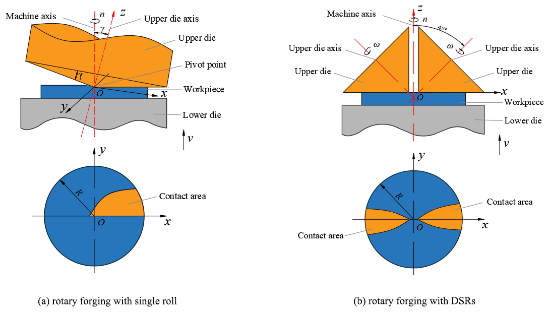
The working principle of conventional rotary forging with a single roll is shown in Fig. 1a. In rotary forging with a single roll, the conical upper die with an inclination angle of γ continuously revolves around the vertical axis of the machine, and the lower die pushes the workpiece vertically at speed v, so as to cause it to deform. The working principle of rotary forging with DSRs is shown in Fig. 1b. Rotary forging with DSRs uses a pair of symmetrical cone rolls with an angle of 45∘ between the cone roll axis and the machine axis. The double cone rolls rotate around the machine axis at a constant speed n under the action of a motor. Simultaneously, the lower die pushes the workpiece vertically at a constant speed feed rate v so as to cause it to contact with the double cone rolls. Under the friction between the cone roll and the workpiece, the cone roll rotates around its own axis and rolls relatively to the workpiece. Under the feed of the lower die, the cone roll compresses the workpiece axially, thus realizing the local continuous accumulated deformation of the workpiece. Finally, the workpiece is formed. Compared with conventional rotary forging with a single roll, due to the symmetrical installation of two upper dies, the action line of the load is coincident with the vertical machine axis, resulting in a more stable process. Rotary forging with DSRs has the advantages of a simple equipment structure, small eccentric load, and long die life.
The calculation of the force and power parameters and the stable rolling conditions of rotary forging with DSRs of large diameter : thickness ratio discs is important to the design of the rotary forging press with double symmetry rolls and the theoretical basis of the numerical simulation. The force condition of the workpiece during the process of rotary forging with DSRs is obviously different from that of conventional rotary forging with a single roll. Therefore, it is very important to establish accurate and reliable calculation formulas of the force and power parameters of the rotary forging press with double symmetry rolls and the stable rolling conditions. Based on the theories of rotary forging and metal plastic forming, the calculation of force and power parameters of the rotary forging press with double symmetry rolls and the stable rolling conditions is studied.
3.1 Calculation of the force and power parameters
3.1.1 Calculation of contact area
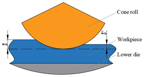
During the forming process of rotary forging with DSRs of large diameter : thickness ratio discs, the contour curve of the contact surface between the cone roll and the workpiece is composed of the intersection curve of the cone roll surface and the upper surface of the workpiece. The contact surface between the cone roll and the workpiece is helical. Since the feed amount of the lower die is much smaller than the radius of the workpiece, the helical surface is regarded as a plane. The contact area between the cone roll and the workpiece is shown in Fig. 2. In the process of rotary forging with DSRs of discs, the surface of the disc can be divided into two parts: contact area (1) and non-contact area (2). Due to the symmetrical distribution of the two rolls, the contact area (1) between the upper die and the workpiece is composed of two symmetrical parts, and the contact area (1) is the active deformation area. The non-contact area (2) is also distributed symmetrically, and the non-contact area (2) is the passive deformation area. Therefore, this paper derives the calculation formula for the contact area between the upper die and the workpiece, i.e. the calculation formula for contact area (1). Due to the symmetrical distribution of the two rolls, the contact area (1) can be divided into two areas: the area OAB and the area ODE. These two surfaces are symmetrically distributed and have an equal area, and the surface OAB is selected for derivation. It can also be seen from Fig. 2 that the surface OAB can be divided into two parts, the surface OAC and the surface OBC. The boundary of the surface OAC is composed of the x axis, the curve OA, and the arc AC. The boundary of the surface OBC is composed of the x axis, the curve OB, and the arc BC. The difference in area between these two surfaces is mainly due to the different feed amount, as shown in Fig. 3. S is the feed amount of the workpiece per revolution of the cone rolls, where , . In addition, all parameters of the two surfaces are the same.
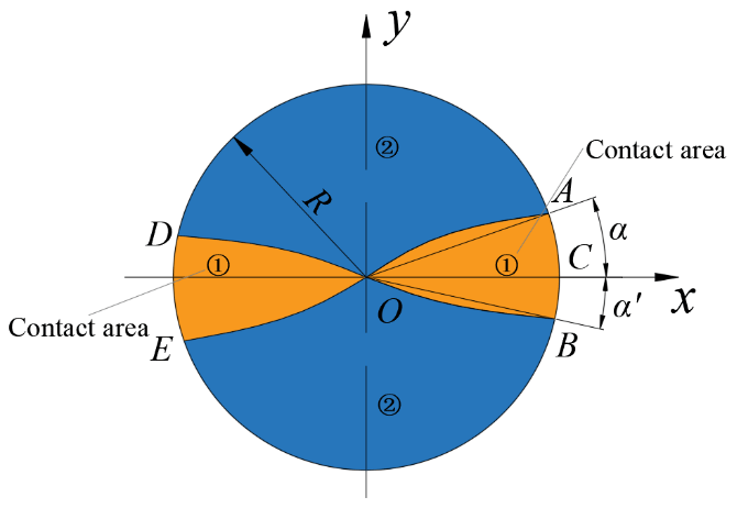
R is the radius of the workpiece. γ is the inclination angle of the upper die, i.e. the angle between the axis of the upper die and the vertical machine axis. In rotary forging with DSRs, . In a three-dimensional coordinate system, the plane equation of the contact surface OAC is
The surface equation of the cone roll is
Therefore, the OA equation of the outer contour curve of the contact surface can be obtained as follows:
So the coordinate of point A (xA,yA) is
Where α is ∠AOC, and α′ is ∠BOC, it can be obtained that
The area FOAC of contact surface OAC is
The area FOBC of contact surface OBC is
Therefore, the area FOAB of contact surface OAB is
The area F of the contact surface (1) between the upper die and the workpiece is
3.1.2 Calculation of forging force
In this paper, the slip line method is used to calculate the forging force of rotary forging with DSRs of large diameter : thickness ratio discs. The slip line field during the forming process is shown in Fig. 4. Where is the ordinate, is the abscissa, and . When the ordinate of a point D on the centre line of the deformation area is γ, ∠BAC of the corresponding sector field is ∅. When and , ha is the initial height of the workpiece, L is the width of the contact area between the cone roll and the workpiece, and ∠BAF of the corresponding sector field is ∅0.
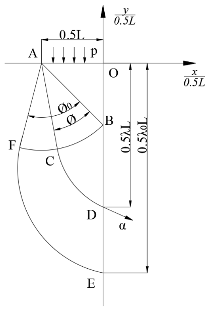
The expression of the functional relation between λ and ∅ is ∅=0.6ln λ. As shown in Fig. 4, the average stress σB and direction angle θB at point B are expressed as
where p is the forging force per unit area, and k is the shear yield strength of the material of the workpiece. When BC is the β slip line, the average stress σC and direction angle θC at point C are expressed as
When CD is the α slip line, the average stress σD and direction angle θD at point D are expressed as
According to the principle of centre equilibrium condition of forces, Eq. (13) can be obtained.
Based on , dy=0.5Ldλ, and , we have
In the OB section and the BE section, the stress field is uniform. Equations (15) and (16) can be obtained respectively.
Based on Eqs. (14)–(16),
Based on ∅=0.6ln λ and ,
In order to calculate the width L of the contact area, the centre radian in the contact area is approximately taken as the width, and Eq. (19) is obtained.
Therefore, the width L of the contact area is Eq. (20).
The calculation formula of the forging force is Eq. (21).
where p is the forging force per unit area, and F is the contact area between the cone roll and the workpiece.
3.1.3 Calculation of forging moment
The schematic diagram of the decomposition of forging force is shown in Fig. 5. The forging force of the cone roll on the workpiece can be decomposed into two directions along the x axis and y axis. It can be seen from Fig. 5 that R′ is the nominal radius of the cone roll. R is the radius of the workpiece. α is the angle between the radius at the feed amount and the y axis. ξα is the angle between the forging force and the y axis, . P1 is the forging force. P1x is the component of the forging force on the x axis. P1y is the component of the forging force on the y axis. According to mechanics, Eq. (22) can be obtained.
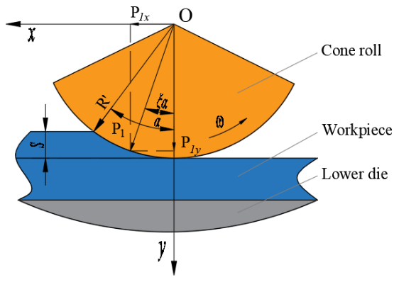
Equation (23) can be obtained from Fig. 5.
When , Eq. (24) can be obtained.
Based on Eqs. (22)–(24), we have
The calculation formula of forging moment is Eq. (26).
Since the taper of the cone roll is γ, the distance between the forging force P1x on the x axis and the rotation axis can be obtained as Eq. (27).
Therefore, the relationship between the nominal radius and the radius of this point can be expressed by Eq. (28).
Based on Eqs. (25)–(28), the calculation formula of forging moment can be obtained as Eq. (29).
3.2 Stable rolling conditions
The mechanical model of stable rolling of the workpiece is shown in Fig. 6. P1 and f1 are the positive pressure and friction force of cone roll 1 to the workpiece, respectively. P2 and f2 are the positive pressure and static friction force of the lower die to the workpiece, respectively. α is the contact angle between the cone roll and the workpiece. μ1 is the rolling friction coefficient between cone roll 1 and the workpiece. μ is the static friction coefficient between the lower die and the workpiece. R′ is the relative radius of the cone roll. S is the feed amount per revolution. ω is the spindle speed. Assuming that the resultant force point of the cone roll on the workpiece is at angle ξα, and ξ is a coefficient, .
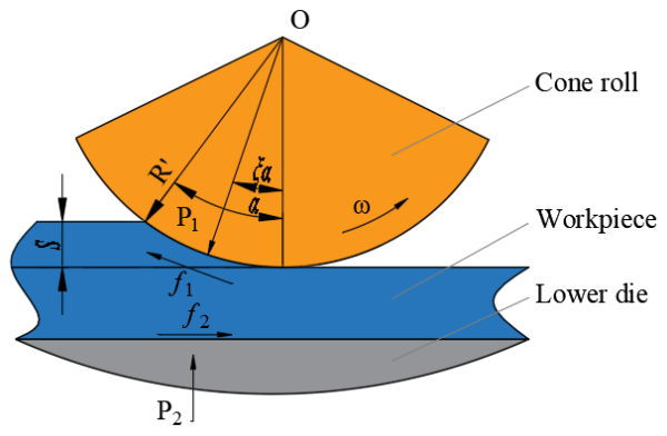
Only when the force of the lower die on the workpiece is greater than or equal to the force of the cone rolls on the workpiece will the workpiece not rotate with the cone rolls, i.e. it is stationary relative to the lower die, then stable rolling can be achieved, and the z direction balance equation can be obtained as follows:
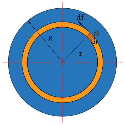
Take the unit area dS with length dl and width dr on the workpiece, and the friction force in the unit area is df. As shown in Fig. 7, the friction moment between the unit area and the lower die is
Therefore, the static friction moment on the whole disc is
The torque balance equation is
According to f1=μ1P1,
Generally, . Equation (3) can be obtained from Fig. 6.
Based on Eqs. (34)–(35), one of the stable rolling conditions of rotary forging with DSRs of large diameter : thickness ratio discs is
The above is an analysis of the workpiece. For the cone rolls, the conditions for rotation of the cone rolls must also be met. f1 is the friction force between the cone roll and the workpiece. T is the friction torque of the cone roll. M is the weight of the workpiece. Therefore, the rotation condition of the cone roll is
Based on Eqs. (38)–(39), Eq. (40) can be obtained.
In conclusion, the stable rolling conditions of rotary forging with DSRs of large diameter : thickness ratio discs are as follows:
In this paper, DEFORM-3D software was adopted to simulate and analyse the forming process of rotary forging with DSRs of large diameter : thickness ratio discs. The three-dimensional finite element model of rotary forging with DSRs of large diameter : thickness ratio discs is shown in Fig. 8.
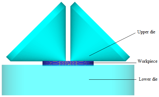
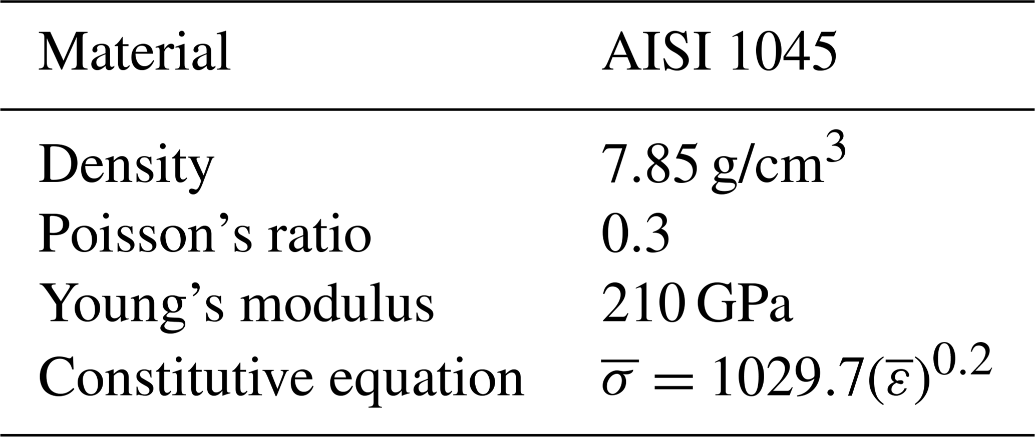
In order to improve the calculation efficiency and accuracy of the results, the workpiece was discretized using a tetrahedral mesh with 32 000 elements and 5692 nodes. Because the elastic deformation is far less than the plastic deformation of the workpiece in the forming process of rotary forging with DSRs of large diameter : thickness ratio discs, the workpiece is defined as a rigid-plastic body. The workpiece material is AISI 1045, and its mechanical properties are shown in Table 1.
Boundary conditions are specified and enforced at the nodes or element edges in the finite element mesh. The main boundary condition in rotary forging is contact boundary condition, which is friction boundary condition. Friction boundary conditions are generally divided into three categories: Coulomb friction, maximum friction, and friction-invariant conditions. Since the rotary forging adopted in this paper is a kind of forming method that belongs to hot rotary forging, the maximum friction condition is selected in the simulation. Friction in the model is defined as
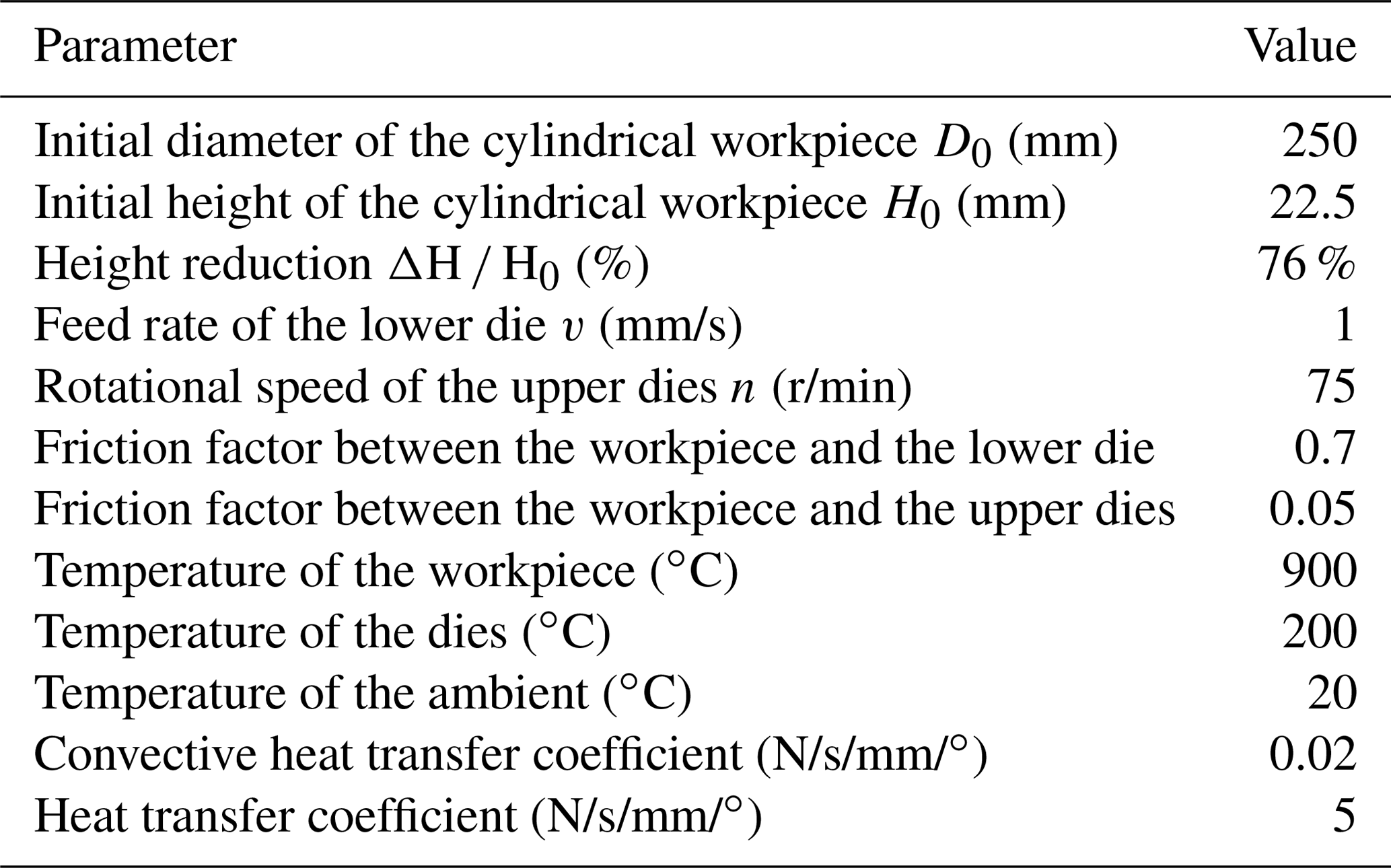
where τf is the friction stress, m is the friction factor, and k is the shear yield stress. In the simulation, the temperature of the workpiece is defined as 900∘. In order to improve the calculation efficiency, this paper adopts a simple heat conduction model, in which the temperature of the die remains constant in the forming process, and the die is set as a rigid body. The die temperature is defined as 200∘, and the ambient temperature is defined as 20∘. The convective heat transfer coefficient between the workpiece and the die and the environment is set as 0.02 N/s/mm/∘, and the heat transfer coefficient between the workpiece and the die is set as 5 N/s/mm/∘. The processing parameters adopted in rotary forging with DSRs of large diameter : thickness ratio discs are shown in Table 2.
Table 2Processing parameters for simulation of rotary forging with DSRs.
4.1 Verification of stable rolling conditions
According to the stable rolling conditions, there are mainly three different kinds of plastic deformation of the workpiece.
The first case is that the feed amount per revolution S is greater than the maximum feed amount allowed for by theoretical calculation, but the cone roll can meet the condition of rotation, as shown in Eq. (43).
The simulation parameters are set according to the deformation condition of rotary forging with DSRs as follows: feed rate of the lower die , revolution speed of the double symmetry rolls , i.e. the feed amount of the workpiece per revolution of the cone rolls , friction coefficient between the cone roll and the workpiece μ1=0.075, and friction coefficient between the lower die and the workpiece μ=0.3. Obviously, this deformation condition does not meet the stable rolling conditions. In order to study the defects and causes of unstable rolling conditions, DEFORM-3D software was used to perform simulation and analyse the deformation process of rotary forging with DSRs of large diameter : thickness ratio discs under the first deformation condition. The deformation process of rotary forging with DSRs of a disc under the first deformation condition is shown in Fig. 9. It can be seen in Fig. 9 that eccentricity and warping defects occur in the deformation process of the workpiece because the feed amount per revolution S is greater than the maximum feed amount allowed for by theoretical calculation, and the workpiece does not reach the final forming state. The main reason for the eccentricity and warping defects of the workpiece is that during the rotary forging process, when the axial strain of the workpiece is constant, the smaller the contact area rate between the cone roll and the workpiece, the narrower and longer the contact area, the greater frictional resistance of the metal radial flow, and the easier the metal flows along the tangential direction, causing the cone roll to fall into the workpiece. Therefore, the workpiece will rotate together with the cone roll, and eccentricity and warping defects of the workpiece are generated.
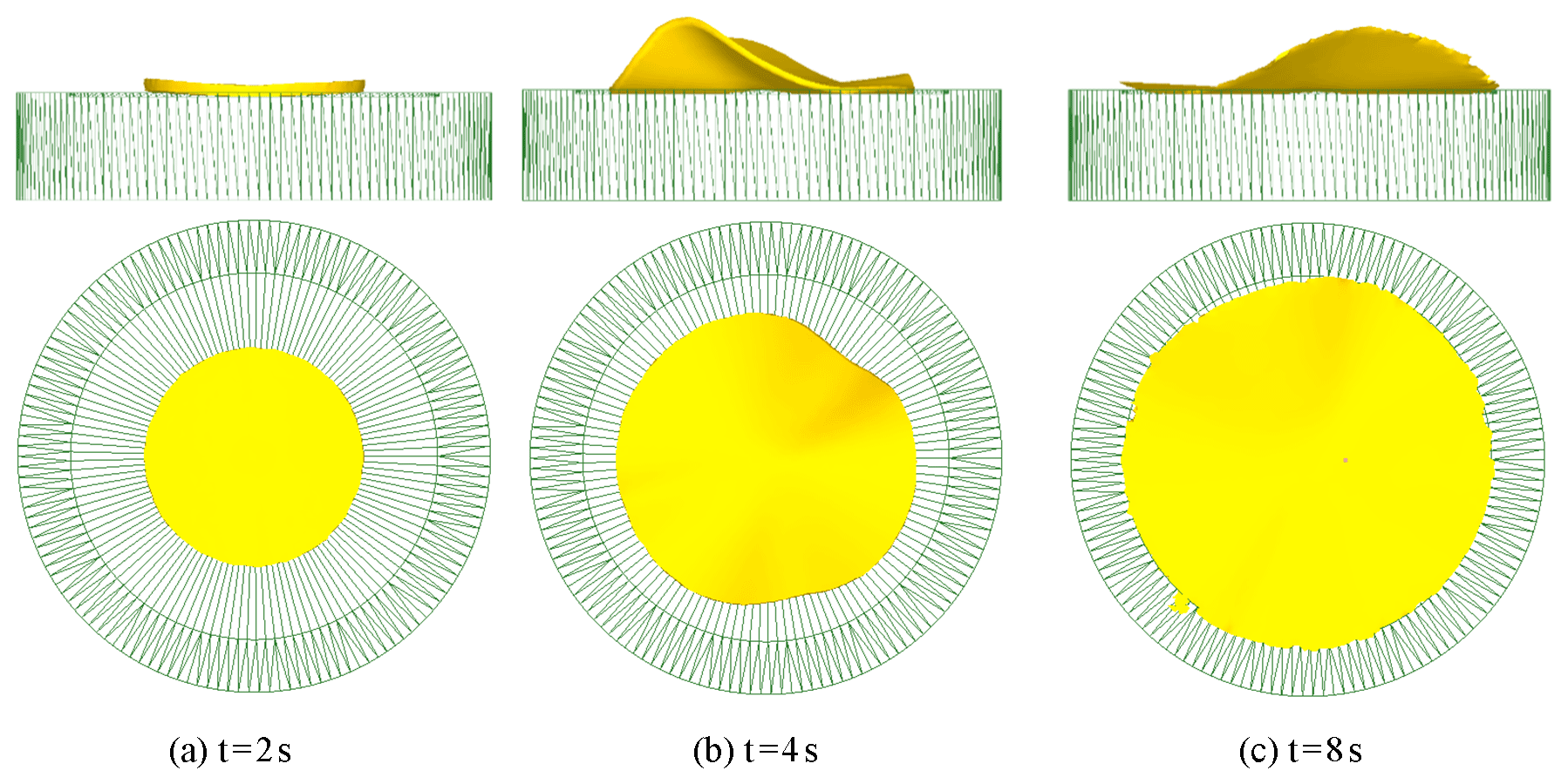
Figure 9Deformation process of rotary forging with DSRs of a disc under the first deformation condition.
The second case is that the feed amount per revolution S is less than the maximum feed amount allowed for by theoretical calculation, but the cone roll cannot meet the condition of rotation; i.e. the revolution speed of the double symmetry rolls n is too high, or the friction coefficient between the cone roll and the workpiece μ1 is much less than that between the lower die and the workpiece μ, as shown in Eq. (44).
The simulation parameters are set according to the deformation conditions of rotary forging with DSRs as follows: feed rate of the lower die , revolution speed of the double symmetry rolls , i.e. the feed amount of the workpiece per revolution of the cone rolls , friction coefficient between the cone roll and the workpiece μ1=0.01, and friction coefficient between the lower die and the workpiece μ=7. The deformation process of rotary forging with DSRs of a disc under the second deformation condition is shown in Fig. 10. As can be seen in Fig. 10, in the initial stage of the deformation, the diameter of the upper surface of the workpiece is larger than the diameter of the lower surface, resulting in an obvious mushroom effect. As the forming process continues, the workpiece begins to warp and lose complete contact with the lower die, and the centre-thinning of the workpiece starts to occur. When the forming process is completed, although the workpiece is flattened, there is a defect of central rupture of the workpiece. The blue dots in the figure indicate that the workpiece is in contact with the lower die, indicating that the workpiece has not completely filled the cavity. The reason for the defects of centre-thinning and even central rupture of the workpiece is that in the forming process, the radial extension is larger than tangential extension; when the small additional radial extension gradually accumulates in the process of rotary forging and acts on the workpiece, the workpiece will have the defects of tensile plastic instability or centre-thinning and even central rupture.
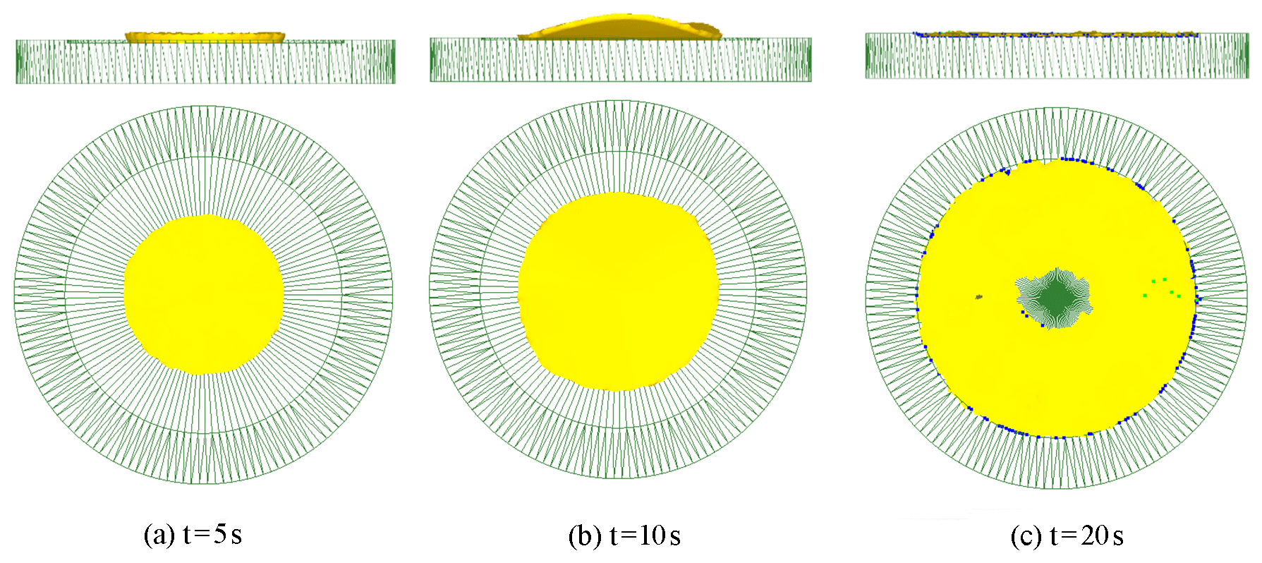
Figure 10Deformation process of rotary forging with DSRs of a disc under the second deformation condition.
The third case is that the feed amount per revolution S is less than the maximum feed amount allowed for by theoretical calculation, and the cone roll meets the condition of rotation, so the stable rolling deformation can be achieved, as shown in Eq. (45).
The simulation parameters are set according to the deformation condition of rotary forging with DSRs as follows: feed rate of the lower die , revolution speed of the double symmetry rolls , i.e. the feed amount of the workpiece per revolution of the cone rolls , friction coefficient between the cone roll and the workpiece μ1=0.05, and friction coefficient between the lower die and the workpiece μ=7. The deformation process of rotary forging with DSRs of a disc under the third deformation condition is shown in Fig. 11. It can be seen from Fig. 11 that the forming process can be divided into three stages. In the first stage, the thickness of the workpiece is too large to achieve complete plastic penetration. The upper surface of the workpiece first reaches the yield condition, and plastic deformation occurs, resulting in the diameter of the upper surface being larger than the diameter of the lower surface, generating the mushroom effect. As the forming process continues, the thickness of the workpiece decreases until the complete plastic penetration is achieved. At this time, the diameter of the lower surface increases faster than the upper surface because it is difficult for the metal to flow on the upper surface of the workpiece. In the final stage, due to the complete plastic penetration of the workpiece and the limitation of the lower die cavity, the lower surface of the workpiece first reaches the required size. As the packing process continues, the diameter of the upper surface of the workpiece increases until the lower die cavity is filled. During the whole forming process, the workpiece has no defects of warping and centre-thinning. According to the contact between the workpiece and the lower die, the filling effect is good.

Figure 11Deformation process of rotary forging with DSRs of a disc under the third deformation condition.
4.2 Surface plastic deformation of rotary forging with DSRs
In order to explore the plastic deformation characteristics of rotary forging with DSRs of large diameter : thickness ratio discs, based on the plastic deformation process of stable rolling conditions, the surface and axial PEEQ (equivalent plastic strain) of the workpiece are analysed in detail. The surface PEEQ distribution of the disc is shown in Fig. 12. It can be seen from Fig. 12 that the PEEQ distribution on the surface of the workpiece diffuses from the centre to the edge, presenting an approximately central symmetrical distribution. In the initial stage of the forming process, due to the small feed amount, both the PEEQ value of the workpiece and the difference are small, as shown in Fig. 12a. As the forming process continues, large plastic deformation zones are generated. Due to the instability of deformation, the distribution of PEEQ is inhomogeneous, and the difference is large, as shown in Fig. 12b and c. In the final stage, when the workpiece is formed, the PEEQ value in the circumferential direction is much larger than that in the centre, and the distribution of the PEEQ in the circumferential direction is more uniform than that in radial direction, i.e. the PEEQ values are basically the same within the same radius, as shown in Fig. 12d.
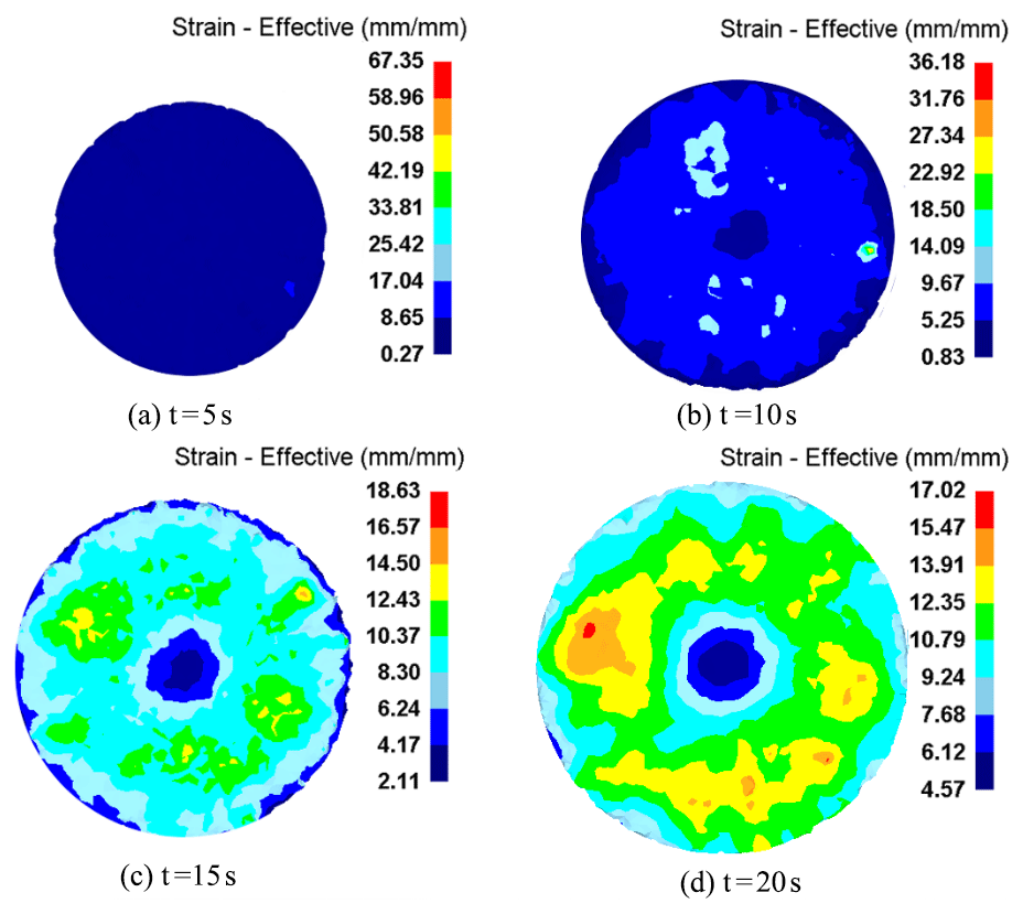
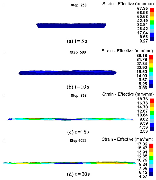

Figure 14Comparison of the contact area between the cone rolls and the workpiece between theoretical calculation and simulation.
4.3 Plastic deformation of axial section of the workpiece
In order to explore the plastic deformation characteristics of rotary forging with DSRs of large diameter : thickness ratio discs, the axial PEEQ of the workpiece is analysed in detail. The PEEQ distribution in the axial direction of the disc is shown in Fig. 13. It can be seen from Fig. 13 that the cone roll first contacts the metal on the upper surface of the workpiece, and the metal on the upper surface of the workpiece first satisfies the yield condition, and plastic deformation occurs, and the plastic deformation zone gradually expands along the radial and axial direction, as shown in Fig. 13a. As the forming process continues, the thickness of the workpiece decreases gradually. The plastic deformation zone penetrates from the upper surface to the lower surface of the workpiece, and the whole workpiece enters the plastic deformation state, as shown in Fig. 13b and c. In the final stage, the workpiece is basically formed. It can be seen that the PEEQ gradually decreases from the upper surface to the lower surface of the workpiece in the axial direction, and the PEEQ value on the lower surface of the workpiece is smallest, as shown in Fig. 13d. During the whole forming process, the maximum PEEQ value is 17.02 mm/mm, and the minimum PEEQ value is 4.57 mm/mm.
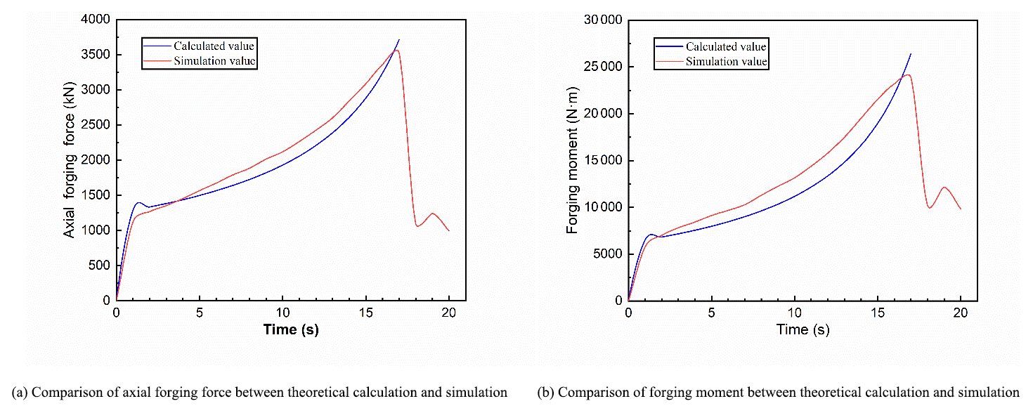
Figure 15Comparison of force and power parameters between theoretical calculation and simulation.
4.4 Verification of force and power parameters by the finite element method
4.4.1 Contact area
Compared with conventional forging technology, the obvious difference of rotary forging with DSRs is that the cone rolls and the workpiece are in partial contact during the forming process. The contact area between the cone rolls and the workpiece is constantly changing due to the continuous revolution of the cone rolls and the continuous change of the diameter of the workpiece. The comparison of the contact area between the cone rolls and the workpiece between theoretical calculation and simulation is shown in Fig. 14. From the contact area curve of simulation in Fig. 14, it can be seen that in the initial stage of forming process, the cone rolls contact the upper surface of the workpiece, and the contact area increases rapidly from zero to a certain value. Since the cone rolls and the workpiece are in partial contact, the workpiece surface warps slightly, and the contact area between the cone rolls and the workpiece fluctuates slightly. As the forming process continues, the diameter of the upper surface of the workpiece is larger than that on the lower surface. It is difficult for the metal to flow on the upper surface of the workpiece, and the diameter increases slowly. Therefore, the contact area between the cone rolls and the workpiece increases slowly. In the final stage of the forming process, after the lower die stops feeding upward, the cone rolls continue to rotate so as to make the upper surface become a plane, and the contact area decreases rapidly. It can be seen from the curve of contact area between the cone rolls and the workpiece that the contact area is always in dynamic change, which is highly nonlinear and nonstationary. According to the comparison between the contact area calculated by Eq. (8) and the contact area of simulation, the error between the theoretical calculation result and the simulation result is small, which proves that the formula derived in this paper is correct.
4.4.2 Axial forging force and forging moment
Force and power parameters are the important basis for designing and manufacturing rotary forging presses and guiding experiments. Force and power parameters in the forming process of rotary forging with DSRs of large diameter : thickness ratio are studied in detail. The comparison of force and power parameters between theoretical calculation and simulation is shown in Fig. 15. It can be seen from Fig. 15 that the curve of the axial forging force and forging moment is divided into three stages. In the first stage, the cone rolls first come into contact with the upper surface of the workpiece, resulting in the plastic deformation of the upper surface of the workpiece, and thus the axial forging force and forging moment increase rapidly from zero to a certain value. In the second stage, with the gradual stabilization of the forming process and the reduction of the thickness of the workpiece, the plastic deformation zone penetrates from the upper surface to the lower surface, and the whole workpiece has entered the steady deformation stage, and thus the axial forging force and forging moment increase slowly up to the maximum value. In the final stage, the lower die stops feeding upward, while the cone rolls continue to rotate, so as to make the upper surface become a plane, thus resulting in less metal participating in plastic deformation. So the axial forging force and forging moment decrease rapidly. In the forming process, the maximum axial forging force and forging moment are 3521 kN and 23 848 N m, respectively. According to Eqs. (20) and (28), the axial forging force and forging moment of theoretical calculation are obtained respectively. Compared with the axial forging force and forging moment of simulation, the error between theoretical calculation results and simulation results is small. The error of forging force is less than 10 %, and the error of forging moment is less than 15 %. The maximum axial forging force and forging moment of theoretical calculation are 3713 kN and 26 409 N m, respectively.

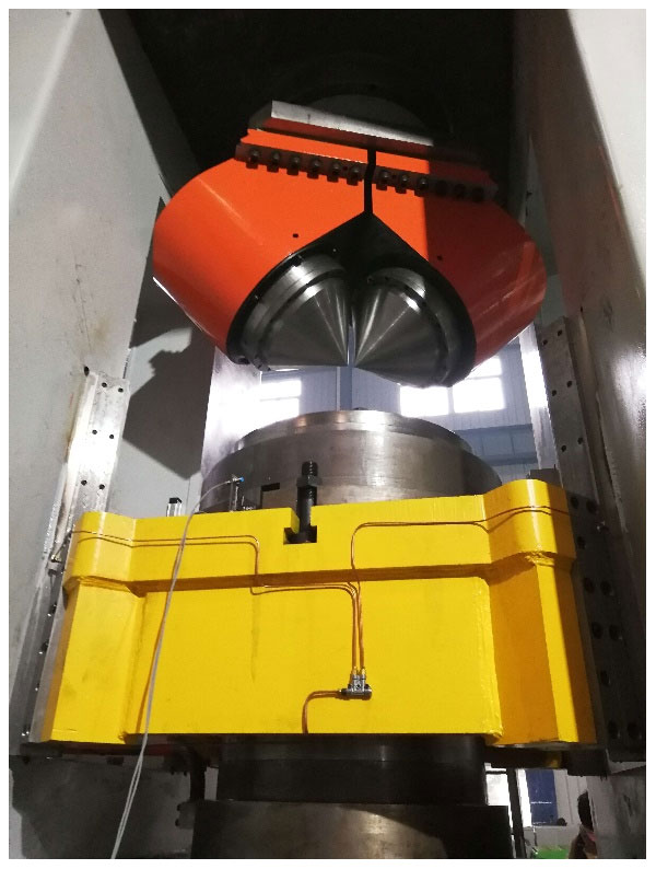
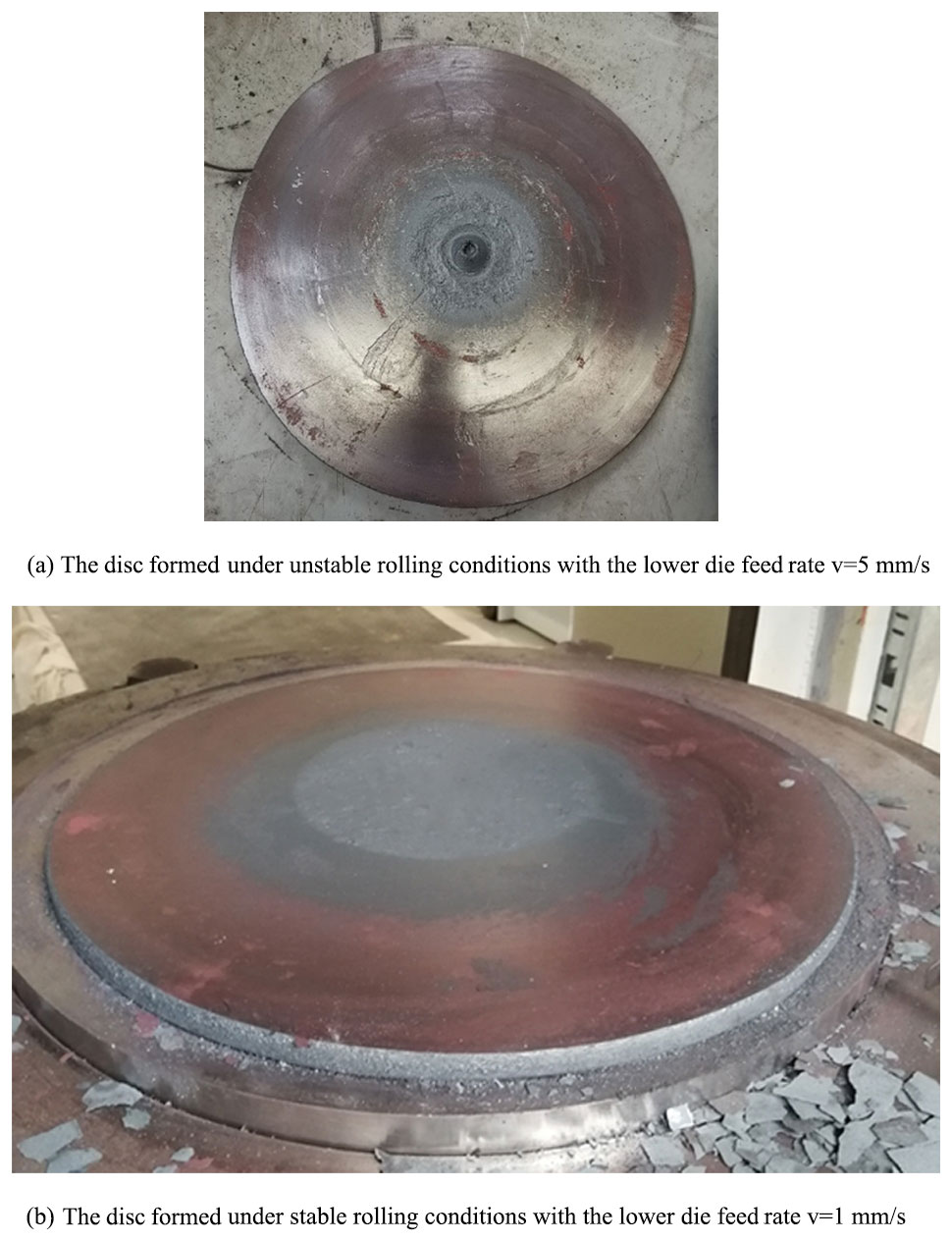
In order to verify the reliability of the stable rolling conditions, calculation formulas of force and power parameters, and finite element simulation of rotary forging with double rolls of large diameter : thickness ratio discs, experiments were carried out on a 500 t rotary forging press developed with double symmetry rolls. The 500 t rotary forging press with double symmetry rolls used in the experiment is shown in Fig. 16. The discs formed on the 500 t rotary forging press with double symmetry rolls are shown in Fig. 17. A disc formed under unstable rolling conditions with the lower die feed rate is shown in Fig. 17a. As can be seen from Fig. 17a, the disc is heavily warped, and the surface quality is poor. A disc formed under stable rolling conditions with the lower die feed rate is shown in Fig. 17b. As can be seen from Fig. 17b, the disc has a good surface quality and a clear outline. It has been proven that the stable rolling conditions and simulation of rotary forging with DSRs of large diameter : thickness ratio discs are reliable.
The comparison of axial forging force between experiment on the 500 t rotary forging press and theoretical calculation is shown in Fig. 18. It can be seen from Fig. 18 that the theoretical calculation results are in agreement with the experimental results, and the error is relatively small, which proves that the calculation formulas for force and power parameters of rotary forging with DSRs of large diameter : thickness ratio discs are reliable.
In this paper, a novel forming process of large diameter : thickness ratio discs is studied, namely rotary forging with double symmetry rolls. At the same time, the plastic deformation law and related calculation formula of large diameter : thickness ratio discs are studied. The following conclusions can be drawn.
-
In this paper, the stable rolling conditions and the calculation formulas for force and power parameters of rotary forging with DSRs of large diameter : thickness ratio discs are derived, which are the theoretical basis of simulation process parameters and experiments.
-
The stable rolling conditions are verified by numerical simulation. When the feed amount per revolution S is greater than the maximum feed amount allowed for by theoretical calculation, the workpiece will rotate together with the cone rolls, resulting in the defects of eccentricity and warping. When the revolution speed of the double symmetry rolls n is too high, or the friction coefficient between the cone roll and the workpiece μ1 is much less than that between the lower die and the workpiece μ, the workpiece will have the defects of centre-thinning or even central rupture. When the process parameters meet the stable rolling conditions, the forming quality of the workpiece is good. The reliability of calculation formulas for force and power parameters is verified by the finite element method.
-
Based on the plastic deformation process of stable rolling conditions, the surface and axial PEEQ of the workpiece are analysed. The PEEQ distribution on the surface of the workpiece diffuses from the centre to the edge, presenting an approximately central symmetrical distribution. The plastic deformation zone first occurs on the upper surface of the workpiece. With the feed of the lower die and the revolution of the cone rolls, the plastic deformation zone penetrates from the upper surface to the lower surface. The PEEQ value decreases from the upper surface to the lower surface of the workpiece in the axial direction, and the PEEQ value of the lower surface of the workpiece is smallest.
-
Experiments were carried out on a 500 t rotary forging press developed with double symmetry rolls. The experimental results are in agreement with the theoretical calculation results, which proves that the stable rolling conditions and the calculation formulas of force and power parameters are reliable.
Data can be made available upon reasonable request. Please contact Chun Dong Zhu (zcdzcd6252@sina.com).
CDZ put forward the method of rotary forging with double symmetry rolls (DSRs) to form large diameter : thickness ratio discs, and he conducted the final examination of the whole paper. RFM studied the theoretical formula derivation, conducted the numerical simulation analysis, and wrote the article. YFG and ZHW performed the experiments to verify the reliability of the theoretical formula and the numerical simulation.
The authors declare that they have no conflict of interest.
The authors would like to thank the National Natural Science Foundation of China (grant no. 51875427) for the support given for this research. In addition, the authors would like to thank the Suizhou-WUT Industry Research Institute (grant no. suikefa [2019]9).
This research has been supported by the National Natural Science Foundation of China (grant no. 51875427) and the Suizhou-WUT Industry Research Institute (grant no. suikefa [2019]9).
This paper was edited by Giovanni Berselli and reviewed by two anonymous referees.
Canta, T., Frunza, D., Sabadus, D., and Tintelecan, C.: Some aspects of energy distribution in rotary forming processes, J. Mater. Process. Technol., 80, 195–198, 1998.
Choi, S., Na, K. H., and Kim, J. H.: Upper-bound analysis of the rotary forging of a cylindrical billet, J. Mater. Process. Technol., 67, 78–82, https://doi.org/10.1016/S0924-0136(96)02822-1, 1997.
Han, X. H. and Hua, L.: Comparison between cold rotary forging and conventional forging, J. Mech. Sci. Technol., 23, 2668–2678, https://doi.org/10.1007/s12206-009-0624-9, 2009.
Han, X. H. and Hua, L.: Prediction of contact pressure, slip distance and wear in cold rotary forging using finite element methods, Tribol. Int., 44, 1742–1753, https://doi.org/10.1016/j.triboint.2011.06.034, 2011.
Han, X. H., Hua, L., Zhuang, W. H., and Zhang, X. C.: Process design and control in cold rotary forging of non-rotary gear parts, J. Mater. Process. Technol., 214, 2402–2416, https://doi.org/10.1016/j.jmatprotec.2014.05.003, 2014.
Han, X. H., Hu, Y. X., and Hua, L.: Cold orbital forging of gear rack, Int. J. Mech. Sci., 117, 227–242, https://doi.org/10.1016/j.ijmecsci.2016.09.007, 2016.
Hua, L. and Han, X. H.: 3D FE modeling simulation of cold rotary forging of a cylinder workpiece, Mater. Des., 30, 2133–2142, https://doi.org/10.1016/j.matdes.2008.08.045, 2009.
Jin, J., Wang, X., and Li, L.:A sheet blank rotary forging process for disk-like parts with thickened rims, J. Mech. Sci. Technol., 30, 2723–2729, https://doi.org/10.1007/s12206-016-0534-6, 2016.
Jin, Q., Han, X. H., Hua, L., Zhuang, W. H., and Feng, W.: Process optimization method for cold orbital forging of component with deep and narrow groove, J. Manuf. Process., 33, 161–174, https://doi.org/10.1016/j.jmapro.2018.05.007, 2018.
Liu, G., Yuan, S. J., Wang, Z. R., and Xie, T.: Finite element model and simulation of rotary forging of a disc, Acta Metall. Sin., 13, 470–475, 2000.
Liu, G., Yuan, S. J., Wang, Z. R., and Zhou, D. C.: Explanation of the mushroom effect in the rotary forging of a cylinder, J. Mater. Process. Technol., 151, 178–182, https://doi.org/10.1016/j.jmatprotec.2004.04.035, 2004.
Liu, X., Zhu, C. D., Jiang, X., and Zhang, Y.: Influence of eccentricity of double eccentricity sleeves on the movements of swing head in rotary forging press, Mech. Sci., 10, 321–330, https://doi.org/10.5194/ms-10-321-2019, 2019.
Liu, X., Zhu, C. D., Sun, S. D., and Ma, R. F.: Rotary forging with multi-cone rolls, J. Manuf. Process., 56, 656–666, https://doi.org/10.1016/j.jmapro.2020.05.037, 2020.
Loyda, A., Reyes, L. A., Hernandez-Munoz, G. M., Garcia-Castillo, F. A., and Zambrano-R0bledo, P.: Influence of the incremental deformation during rotary forging on the microstructure behaviour of a nickel-based superalloy, Int. J. Adv. Manuf. Technol., 97, 2383–2396, https://doi.org/10.1007/s00170-018-2105-8, 2018.
Oh, H. K. and Choi, S.: A study on center thinning in the rotary forging of a circular plate, J. Mater. Process. Technol., 66, 101–106, https://doi.org/10.1016/S0924-0136(96)02502-2, 1997.
Pérez, M.: Microstructural and texture evolution of Jethete M152 flanged-test pieces during cold rotary forging, J. Mater. Process. Technol., 252, 582–594, https://doi.org/10.1016/j.jmatprotec.2017.10.012, 2017.
Sheu, J. J. and Yu, C. H.: The die failure prediction and prevention of the orbital forging process, J. Mater. Process. Technol., 201, 9–13, https://doi.org/10.1016/j.jmatprotec.2007.11.178, 2008.
Shi, L., Zhu, C. D., Liu, X., and Zhang, Y.: Optimum design of the double roll rotary forging machine frame, Mech. Sci., 11, 101–114, https://doi.org/10.5194/ms-11-101-2020, 2020.
Wang, G. C. and Zhou, G. Q.: A three-dimensional rigid–plastic FEM analysis of rotary forging deformation of a ring workpiece, J. Mater. Process. Technol., 95, 112–115, https://doi.org/10.1016/S0924-0136(99)00268-X, 1999.
Wang, G. C., Guan, J., and Zhao, G. Q.: A photo-plastic experimental study on deformation of rotary forging a ring workpiece, J. Mater. Process. Technol., 169, 108–114, https://doi.org/10.1016/j.jmatprotec.2005.03.003, 2005.
Yuan, S. J., Wang, X. H., Liu, G., and Chou, D. C.: The precision forming of pin parts by cold-drawing and rotary-forging, J. Mater. Process. Technol., 86, 252–256, https://doi.org/10.1016/S0924-0136(98)00321-5, 1999.
Zhang, M.: Calculating force and energy during rotary forging, Proceedings of the third international conference on rotary metalworking processes, 115–124, 1984.
Zhao, Y. M. and Han, X. H.: Rotary forging with double symmetry rolls, Ironmak. Steelmak., 37, 624–632, https://doi.org/10.1179/030192309X12573371383758, 2010.
Zheng, Y., Liu, D., Zhang, Z., Yang, Y. H., and Ren, L. J.: The flow line evolution of hot open ACDR process for titanium alloy discs, Arch. Civ. Mech. Eng., 17, 827–838, https://doi.org/10.1016/j.acme.2017.03.005, 2017.
Zheng, Y., Liu, D., Yang, Y. H., Zhang, Z., and Li, X. L: PDZ evolution of hot ACDR and forging processes during titanium alloy disc forming, Int. J. Adv. Manuf. Technol., 95, 1635–1643, https://doi.org/10.1007/s00170-017-1135-y, 2018.
Zhou, D. C., Han, Y. D., and Wang, Z. R.: Research on rotary forging and its distribution of deformation, J. Mater. Process. Technol., 31, 161–168, https://doi.org/10.1016/0924-0136(92)90016-L, 1992a.
Zhou, D. C., Yuan S J., and Wang, Z. R.: Defects of WorkPieces Producing in Forming Process of Rotary Forging and Methods for Preventing Them, Hot Working Technol., 1, 35–37, https://doi.org/10.14158/j.cnki.1001-3814.1992.01.012, 1992b.
Zhu, C. D., Guan, Q., and Wang, H.: Twin symmetry roll axial rolling: new method of plastic forming profiles demonstrated using manufacture of spiral bevel gears, Ironmak. Steelmak., 38, 211–217, https://doi.org/10.1179/030192310X12827375731500, 2011.
Zhu, C. D., Jiang, X., and Dai, T. L.: Research on technology of twin rollers rotary forging of spiral bevel gears, Ironmak. Steelmak., 42, 632–640, https://doi.org/10.1179/1743281215Y.0000000019, 2015.
Zhuang, W. H. and Dong, L. Y.: Effect of key factors on cold orbital forging of a spur bevel gear, J. Cent. South Univ., 23, 277–285, https://doi.org/10.1007/s11771-016-3071-7, 2016.
- Abstract
- Introduction
- Working principles of rotary forging with DSRs
- Stable rolling conditions and calculation of force and power parameters
- Results and discussion
- Experimental verification
- Conclusions
- Data availability
- Author contributions
- Competing interests
- Acknowledgements
- Financial support
- Review statement
- References