the Creative Commons Attribution 4.0 License.
the Creative Commons Attribution 4.0 License.
 | 20 May 2021
Vibroacoustic characteristics analysis of a planetary gear reducer considering the exterior housing structure
Lihong Jin
Junpeng Shao
Yongmei Wang
Baixue Fu
Previous studies have attempted to identify weak links in the dynamic characteristics of the planetary gear reducer (PGR) exterior body structure (EBS). Through numerical simulation, these studies analyzed the mode and natural frequencies and the vibration types of each order of the EBS. However, these scholars have never focused on the main factors affecting the dynamic characteristics of the EBS of this subject. This study in the topic has analyzed the vibroacoustic characteristics of an EBS and optimized its design using numerical simulation. Herein, the contribution of the vibration transfer path from the excitation points on the exterior body to the machine foot is emphatically revealed, and the influences of the main structural parameters on the transfer characteristics are discussed. An optimal EBS for a PGR with lower acoustic vibrations is designed in detail, and a composite EBS with damping vibration attenuation and acoustic absorption is proposed. The radiation acoustic characteristics without acoustic protection and damping materials are analyzed. These research results are implemented in order to realize the dynamic characteristics, transmission, and radiation acoustic characteristics as objects of optimization, and the structural design parameters of the PGR exterior body are deeply optimized using dynamic modification and sensitivity analysis. This topic focuses on the vibroacoustic coupling of EBS in stationary fluid and average flow field. Based on the analysis method of theoretical modeling and numerical calculation, the EBS dynamic response and vibroacoustic characteristics under the action of frontal excitation external acoustic flow field are studied, which will be beneficial to explore the comprehensive optimization design of PGR dynamic and vibroacoustic properties.
- Article
(9503 KB) - Full-text XML
- BibTeX
- EndNote


The dynamic characteristics of a planetary gear reducer (PGR) housing have different influences due to their working conditions. In general, the housing of PGR housing is an elastic support that houses the structures of planetary gears, bearings, shafts, and other structures. When a PGR is in operation, internal excitations such as the meshing force of the tooth surface in the alternating meshing process of gears are transmitted to the housing through the structures. During the transmission process, the housing and the gear shaft influence each other. In other words, the housing structure influences the forced vibration of the gear-shafting system and the characteristics of the vibrations and acoustics source (internal excitation force) of the PGR through the vibroacoustic radiation mechanism. Thus, the excitation load of the forced vibration causes the housing structure to housing produce elastic vibrations by itself. However, the vibration energy inside the reducer is transferred to the adjacent hull structure (such as base and floating raft) and the cabin environment in the form of elastic vibrations of the housing, causing the hull structure vibration and cabin acoustics problem. Therefore, the housing characteristics of the excitation source in the housing structure of the PGR and the influence of the hull structure vibroacoustics and the structural vibration as well as the structural impedance parameters of the dynamic characteristics of the PGR are closely related.
Many experimental and theoretical studies have analyzed the dynamic characteristics of the planetary gear. For example, the inherent vibration characteristics of a planetary gear system are proposed, and a time-varying dynamic model of a multi-DoF system is established, and its natural frequency and mode shape is calculated (Morgado et al., 2008). The effects of rotation speed of a planetary frame and the supporting stiffness of a planetary gear on the natural characteristics of the system are also studied numerically. The relationship between the natural frequency trajectories of the system in terms of the relative position of its gears is investigated, and the conditions for the generation of mode transition are established (Renno and Mace, 2014). They also have described modal transition and its influence on the dynamic characteristics of a gear system using a quantitative method. Wang et al. (2018a) developed an analytical-finite-element model for calculating time-varying mesh stiffness of spur gear pairs with complicated foundation (thin web and holes) and crack. The pinion and gear foundations were simulated as cylinders and modeled by three-dimensional finite element. Wang et al. (2018) proposed an improved time-varying mesh stiffness (TVMS) model of a helical gear pair, in which the total mesh stiffness contains the common transverse tooth bending stiffness, transverse tooth shear stiffness, transverse tooth radial compressive stiffness, transverse gear foundation stiffness, and Hertzian contact stiffness.
Considering the time-varying meshing stiffness, eccentricity error, and comprehensive meshing error of a planetary gear, Berry et al. (2014) have proposed a complete dynamic model of the planetary gear transmission system (PGTS). The dynamic response of the PGTS and the frequency domain history of the dynamic load coefficient have been obtained using a numerical method. The nonlinear dynamic model of the PGTS is established by considering nonlinear factors such as time-varying meshing stiffness and gap error. They have developed the model using the harmonic balance method and the Gill method. Mironova et al. (2017) have analyzed the time-varying characteristics of meshing stiffness, transmission error of the PGTS, and phase problem in the meshing process. Considering the time-varying stiffness of a rolling bearing, Suslin and Pilla (2017) have established a gear-bearing coupling dynamic model of a wind turbine PGTS, and they calculated the frequency and dynamic response of the torsional vibration structure of a three-stage planetary gear. The dynamic meshing force of each gear pair and the dynamic contact force of the rolling bearing under random wind load are also discussed.
The acoustics inside the housing of a PGR, which is based on the optimized design of housing structures, is becoming increasingly significant (Hwang et al., 2017). Some researchers have constructed accurate vibroacoustic finite element analysis (FEA) models of house structures to achieve reliable design and analysis (Lin and Zhang, 2018). However, experience has shown that vibration and acoustic predictions using these models were often did not correlate with the experimental results, so these models should be updated (Zhou et al., 2020). In the model updating framework, the influence of housing structure and vibroacoustic parameters on the stiffness and damping modeling errors should be considered simultaneously to obtain an accurate estimation of those parameters (Sánchez et al., 2017; Acri et al., 2019). It should also be noted that acoustic absorption characteristics usually depend on the frequency. This makes it difficult to update the vibroacoustic FEA model based on modal data. Wang et al. (2021) proposed a mesh stiffness model of spur gear pairs with misalignment and lead crown relief based on the slice theory. The slice coupling was simulated as a spring, and the corresponding model was developed.
In this perspective, a FEA method based on vibroacoustic response is proposed. Parameters related to the structural vibroacoustic model of the PGR housing were considered, and the coupling FEA models were modified. The effectiveness of the method was verified by numerically simulating the housing with a damping material used in three-dimensional PGR.
The housing structural vibroacoustic characteristics analysis is an important research topic in the optimization design of PGR (Garambois et al., 2017). In this study, the coupling vibration analysis models of the housing structure, planetary gear, and shafting are established. Combined with the relationships between the housing structural parameters, as well as vibroacoustics, the leading transmission component and method of vibroacoustics are analyzed. The structural form and size of the housing are designed based on the impedance mismatch principle and the acoustic reduction technology of the damping acoustic material. Meanwhile, damping and sound-absorbing materials are reasonably selected. Finally, a low-acoustics structural design method for the housing structure of the PGR is proposed. Such a design should significantly reduce the vibration and acoustics of the PGR in critical structures such as submarines.
In addition, vibration and noise reduction can be achieved by manipulating the dynamic characteristics of the housing with additional damping material (Wu et al., 2019; Hu et al., 2017; Weis et al., 2017). The results show that stiffness and mass are two factors that affect the actual attenuation of the locally resonant damping structural housing. The locally resonant PGR is much heavier than the housing itself, which is disadvantageous to engineering applications (Liang et al., 2018; Yang et al., 2021; Ege et al., 2018). The increasing demand for stable performance in harsh environments such as vibration and noise has led to the noise control problem of PGR housings to the forefront (Arasan et al., 2021; Guo et al., 2014; Kosała, 2019). The results showed that the vibration of the housing structure, sound field, and damping coupling interface affected the noise in the PGR (Marchetti et al., 2020). The vibration of the housing structure produces noise, which in turn produces an additional response to the housing structure because of the sound pressure (Rosa et al., 2020; Bi et al., 2017; Tomilina, 2015). Acoustic analysis of a housing structure with an acoustic damping coupling system based on the finite element method can predict the vibration and noise of the entire structure of PGR in the initial design stage. This analysis can be widely used in the vibration and noise control design of heavy industrial reducers.
The remainder of the paper is structured as follows. Section 2 details the derivation of the motion differential equations of structural–acoustic coupling of a PGR housing based on numerical simulation. Section 3 analyzes the dynamic characteristics of the PGR housing. Section 4 demonstrates the radiation acoustic characteristics of a PGR housing without acoustic protection and damping materials. Furthermore, it details the optimal design of the housing structure of a PGR with low acoustics. Finally, a composite structure that can attenuate the damping vibration and absorb the acoustics of the PGR housing is proposed.
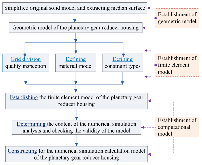
In this study, housing it is necessary to ensure that the dynamic characteristics of the PGR's housing structure remain unchanged with respect to the acoustic properties. An acoustic model of the housing structure is established using median surface extraction, finite element partition, load, and boundary condition setting. Figure 1 presents the general process of finite element analysis (FEA) of the housing structure.
Based on the geometric topological structure model of the PGR's housing with median surface characterization, HyperMesh software was used to extract the median of the reducer housing of upper and lower surfaces, and the end covers of the front and rear surfaces were extracted using HyperMesh. Coupled FEA models of the volumetric and surface grids were established, which were then imported to ABAQUS to construct the computational models for analysis. The reducer housing structure with a relatively small thickness was discretized by a housing element, the thick base structure was discretized by the combination of housing and solid elements, and the restraint and damping layers were modeled by the laminated plate equivalent method. The simplified form of a multilayer damping material element of the housing structure is presented in Fig. 2. The damping layer is regarded as a rigid body moving in a 2a×2b region with an average acceleration. Furthermore, the damping layer is subjected to a concentrated force from the restraint layer and the lateral shear force on the edges of the polygon. According to Newton's second law, the dynamic differential equations of the primary and secondary damping layers (Daneshjou et al., 2017; Rohan and Lukeš, 2019; Dai et al., 2021) were derived as follows:
where . m1 and m2 are expressed as two mass parameters of the PGR exterior body, k1 and k2 are respectively different spring damping constants attached to the PGR exterior body, and the unit mass displacements of the primary and secondary damping layers are described by and , respectively. ξ1 and ξ2 are the relative damping coefficients, respectively. ω represents the natural frequency of a structure with constrained damping.
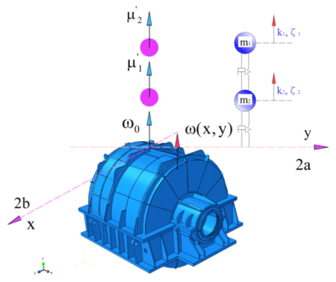
Unlike the traditional reducer exterior body, the basic exterior body of the reducer exterior body has two masses m1=180 g and g with different spring damping constants k1 and k2 attached to exterior body. Then, Hz. The edge lengths of the multilayer damping material sheet in the x, y, and z directions are 2a=220 mm and 2b=220 mm, and the effective thickness of the damping layer h=14.2 mm. The unit mass displacements of the primary and secondary damping layers are denoted by and , respectively.
To solve the specific problems in engineering applications, a reasonable analytical model should be adopted. The numerical analysis aims to restore the mathematical behavioral characteristics of an actual engineering system. Computational models are derived from geometric models, and highly efficient and compact geometrical models are a prerequisite for all subsequent work. Moreover, the establishment of effective models is based on dynamic analysis. The physical model of the PGR housing with damping mass was obtained via dynamic analysis to ensure that the structure of the fixed end, such as the floating raft and the base of the reducer housing, model would be simplified.
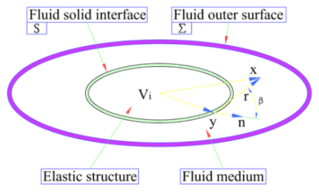
When an elastic structure is placed in a fluid medium, an interaction domain between the fluid and the interface of the elastic structure appears. The influence of structural vibration and boundary fluid is mutual. Furthermore, the entire system constitutes a structure–fluid coupling vibration problem. As shown in Fig. 3, the three-dimensional elastic structure of any shape placed in the fluid has been considered, which is subjected to structural vibration problems from internal loads.
Given that the elastic structures are modeled by FEA, the motion differential equations of the elastic structures are expressed as follows:
where, for the coupled model, [M], [C], and [K] represent the mass, damping, and stiffness matrices of elastic structures, respectively; , , and {u} are the vectors of acceleration, velocity, and displacement of the elastic structure, respectively; and {f} represents the vector of the structural load, [D] is the matrix of the orthogonal transform, and [E] represents the diagonal area matrix of the structural fluid boundary surface. The matrix generated by the product of [D] and [E] is expressed as a pressure vector of fluid in the negative direction transformed into a structural load vector on the principal material coordinate, and {p} is the vector of fluid pressure. It is assumed that all pressures, displacements, and velocities are time-dependent eiϖt functions. For the non-damping structural acoustic system, the discrete form of the dynamic equilibrium equation is
where is the impedance matrix of the elastic structure. The coupled interface in a structural–acoustic system should satisfy the correlation condition of displacement and pressure. Then, Eq. (4) can be denoted as
where {V}, {F}, and {p} represent the structural velocity vector, structural load vector, and amplitude vector of the fluid pressure vector, respectively. Further, ω is the circular frequency of the structural–acoustic coupled system under non-damping.
Similarly, the systems should also satisfy the correlation condition of the median surface forces and moments of the damping layer (Li et al., 2019; Wang et al., 2018b). As shown in Fig. 4, the median surface forces of the damping layer can be derived as follows:
where , .
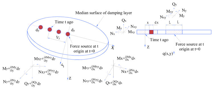
Thus, the median surface moments of the damping layer can be expressed as follows:
where , .
As indicated in Fig. 4, the interaction and energy transfer occur only when the bending mode causes a change in the fluid volume of the damping layer. The damping layer is one of the most important factors affecting the natural frequency of a PGR. The damping layer encompasses the housing and is fixed by the restraint layer. The mass and stiffness of the damping layer and the restraint layer are smaller than those of the housing. Therefore, the two layers are simplified as a mass point distribution on the steel housing structure, as shown in Fig. 5.
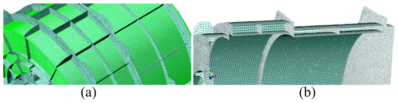
Figure 5Damping layer and constraint layer are simplified as a mass point distribution on the steel housing structure: (a) simplified structure model of the damping layer and (b) simplified structure model of the constraint layer.
The FEA model is different from the actual structure, and self-modeling defects of the model cannot completely reflect the actual structure. In this section, the effectiveness of the finite element mesh models is verified by the modal analysis method. The verification procedure is as follows:
-
A modal analysis of each individual component is performed to verify the finite element mesh quality, node association, and overlapping element problems of the component model.
-
A modal analysis of the integral FEA model was performed to verify the comprehensive and effective definition of various contact conditions among different components.
-
A modal analysis of the entire FEA model is proposed, and the modal mass, moment of inertia, and natural frequency of the model are obtained and compared with the actual structure.
In this special topic, an adequate number of modes within the range of the frequency extraction analysis step were extracted. The effectiveness of the FEA model was verified by the first four-order modal analysis of the PGR structure, including the transmission shaft and the base (Fig. 6).
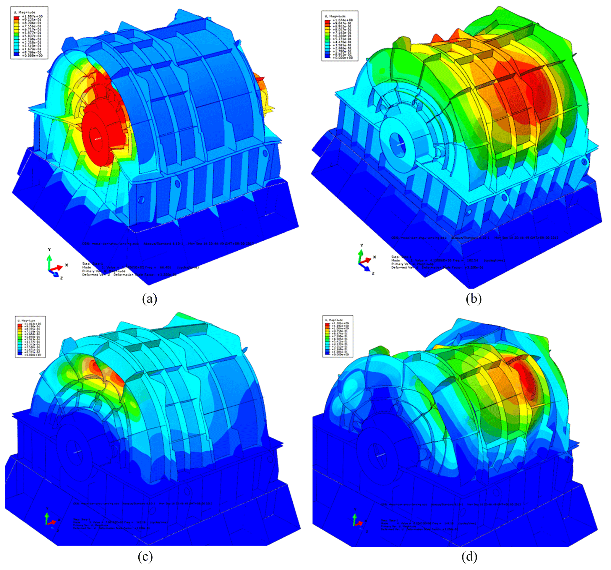
Figure 6First four orders of the PGR's housing structure (including the transmission shaft and the base): (a) first-order mode (67.51 Hz), (b) second-order mode (103.65 Hz), (c) third-order mode (153.30 Hz), and (d) fourth-order mode (145.29 Hz).
As illustrated in Fig. 6, the modal analysis revealed no distortion element in the FEA model of the housing structure. Figure 6 indicates that the nodes are interconnected and that the FEA model is optimal. The total effective mass in the main direction of motion is 90 % higher than that of the criterion of the judgment of movable mass in the models. Therefore, the validity of the models is verified, and the models can be applied to the numerical simulation of the vibration response. In the following section, we use the finite element models to study the behavior of dynamic characteristics of the PGR housing.
2.1 Analysis of the dynamic characteristics of the PGR housing
In this section, the effects of acoustic treatment on the dynamic characteristics of the housing structure are discussed, and the influences of different acoustic treatments and installation and connection conditions on the dynamic characteristics of the housing are considered. The vibration modes and natural frequencies of the housing before and after acoustic treatment were compared and analyzed. Table 1 describes the first 10 natural frequencies and modes of the housing structure before and after the acoustic treatment.
Table 1Description of the first 10 natural frequencies and modes of the housing structure before and after acoustic treatment.
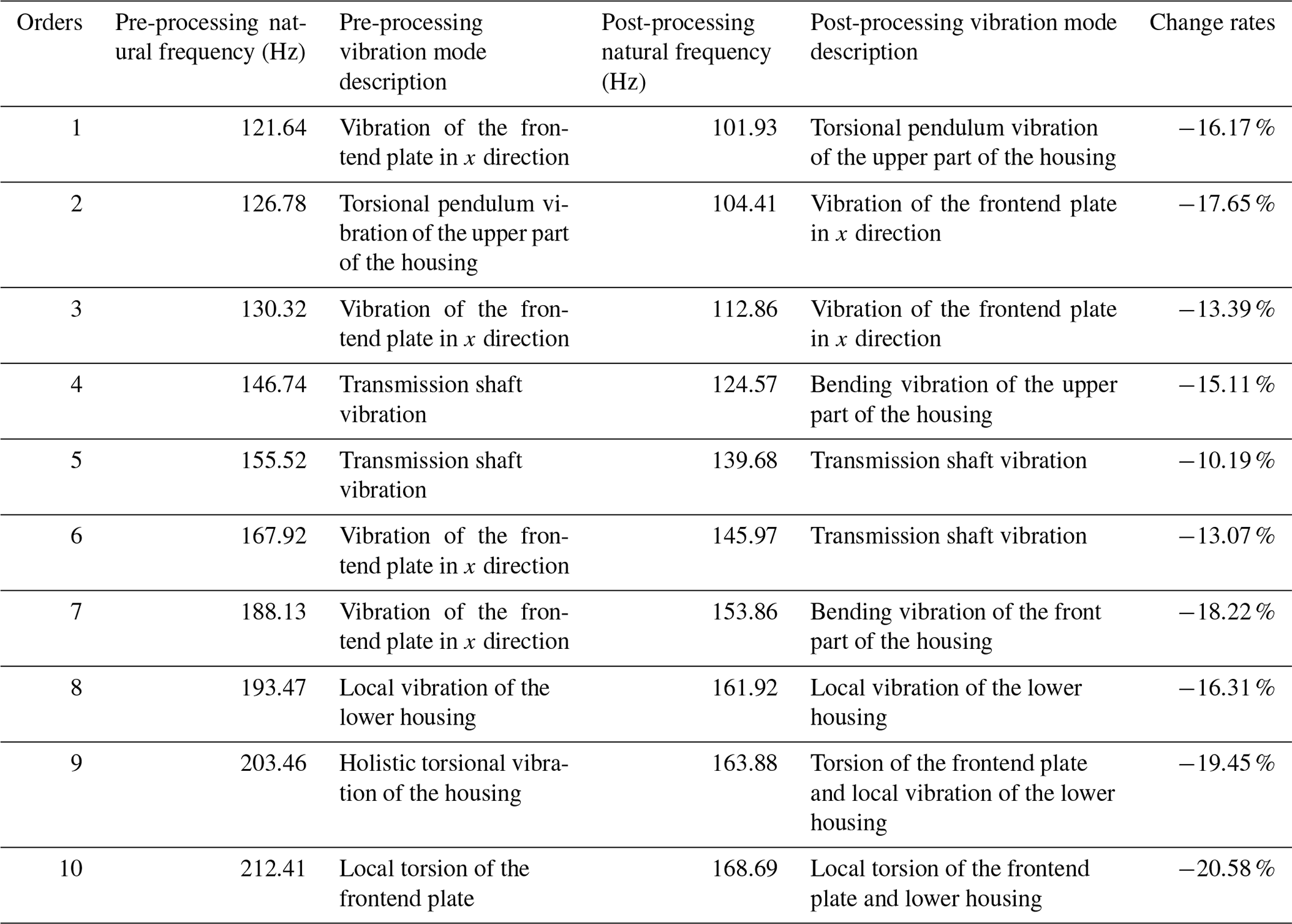
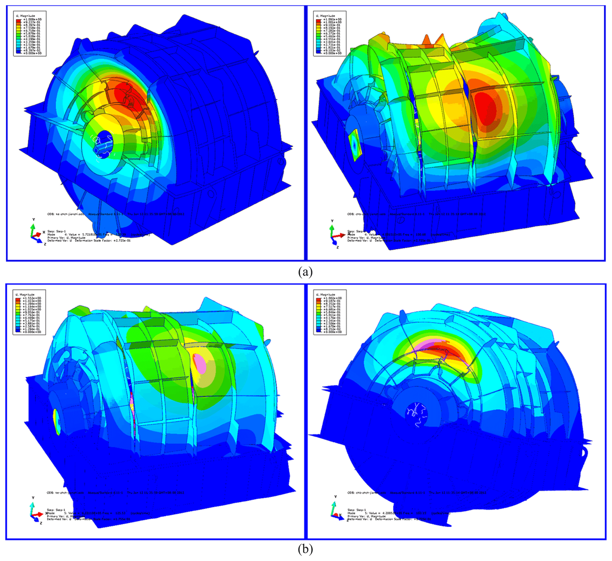
Figure 7First two orders of modal shapes in a cloud pattern in the actual installation state of housing structure before/after acoustic treatment: (a) first-order mode before (left) and after acoustic treatment (right) and (b) second-order mode before (left) and after acoustic treatment (right).
The first two orders of modal shapes of the front and rear housing structures before and after the acoustic treatment are shown in Fig. 7. The figure also indicates that the results considered in the structure coupling state between the parts of the PGR are optimal, and the accuracy of the FEA model is proved. After acoustic treatment, the natural frequency of the housing is greatly decreased. It can be observed that the change in the quality of the housing is greater than that of the stiffness. Before and after acoustic treatment, the modal shape changes significantly and has a certain similarity. Ignoring the influence of the transmission shaft and base, the first two orders of modes were dominated by local vibration, and the connection between the frontend plate and the upper housing was the most violent. In the following section, the radiation acoustic characteristics of the PGR housing with non-acoustic protection and damping materials are analyzed and studied.
2.2 Radiation acoustic characteristics with no acoustic protection or damping materials
Before calculating and analyzing the vibroacoustic characteristics of the housing structure, it was necessary to analyze the response of each part to the excitation force. The transfer function can be used to evaluate the response of different parts of the housing to excitation, thus optimizing the structural characteristics.
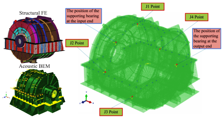
The small vibration of the planetary reducer housing is caused by the excitation force; hence, the response signal (displacement, velocity, or acceleration) was obtained at the examination site where the excitation source was present. Figure 8 depicts a schematic diagram of the positions of the excitation points of the housing structure. As observed clockwise from the input side to the output end, the position of the excitation force housing is located on the bearings at the input housing and output ends of the housing, respectively, where point 1 is the direction of 12:00 UTC+8 (Chinese standard time), point 2 the direction of 03:00, point 3 the direction of 06:00, and point 4 the direction of 09:00, and x is the horizontal direction and y the vertical direction. Based on the established FEA models, the boundary element method (BEM) flow field was established at a distance of 5 m from the housing structure. A square data collection grid was established at a distance of 1 m from the outer layer of the damping plate, as shown in Fig. 9. A total of 13 data collectors were arranged on each surface of the square (acoustic test points), and the BEM flow field was manually connected to the boundary element grid of the housing subsystem.
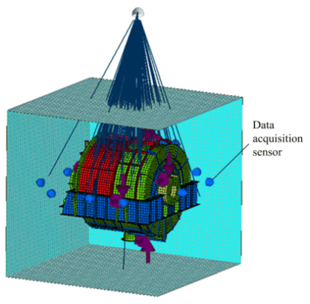
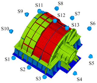
Figure 9 illustrates the establishment of the BEM flow field and boundary element calculation model for the radiated acoustic sound field. Figure 10 presents the layout of the acoustic test points on the housing structure. The material of the PGR housing is Q235 steel. The radiated acoustics of the housing structure was estimated, and the proportion of acoustic radiation of each part of the housing in the total acoustics was evaluated. The contribution of acoustics and the influence of structural parameters on acoustic characteristics were analyzed.
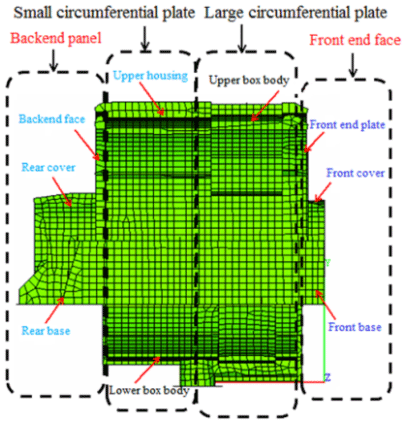
Considering the housing structure in practice, the loss factor of the housing structure is set to 0.002. Here, it is assumed that the loss factor housing does not change with the frequency. To compare the radiated acoustics in each part of the housing, the housing is divided into four parts: frontend face, large circumferential plate, small circumferential plate, and backend panel (Fig. 11). Figures 12–15 demonstrate the spatial distributions of the acoustic radiation sound pressure on the backend panel, small and large circumferential plates, and frontend face, respectively.
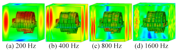
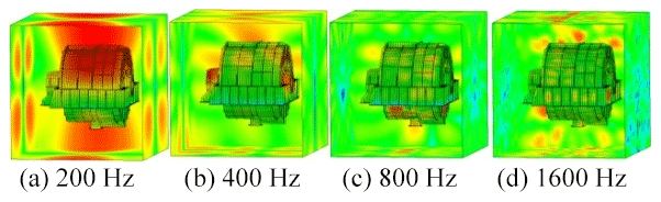
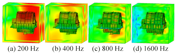
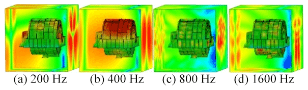
These figures illustrate that the radiation sound pressure of the frontend face and the large circumferential plate is larger than that of the backend panel and the small circumferential plate in the low-frequency section (≤400 Hz). The vibration between the frontend face and the large circumferential plate is relatively large. In the medium- and high-frequency ranges (>400 Hz), the radiated sound pressure of the backend panel and the small circumferential plate increases gradually, and the sound pressure is higher than those of the frontend face and the large circumferential plate. Therefore, in the medium- and high-frequency bands, the vibrations of the backend panel and the small circumferential plate are the main manifestations.
To better understand the feasibility of the practical design of the housing structure, the design was re-simulated on HyperWorks. The final optimal design scheme is as follows.
Both the acoustic insulation layer and the restraint layer were made of a Q235 steel housing structure, the thicknesses of which were set to 5 mm. The thickness of the damping layer was set to t=30 mm, Young's modulus to Pa, and loss factor to η=0.5. As a sound-absorbing protective measure, we used 30 mm thick mineral cotton. The curves of vibration acceleration, velocity, and sound pressure level for the test points at typical locations before and after the use of acoustic materials are shown in Figs. 16–24.
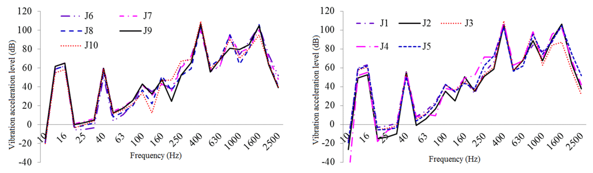
Figure 16One-third octave response curve of vibration acceleration in typical housing parts under original structural conditions.
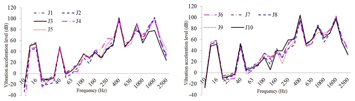
Figure 17One-third octave response curve of vibration acceleration in typical housing parts under constrained damping conditions.
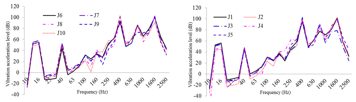
Figure 18One-third octave response curve of vibration acceleration class of typical housing parts under restrained damping and acoustic protection conditions.

Figure 19One-third octave response curve of vibration intensity in typical housing parts under original structural conditions.
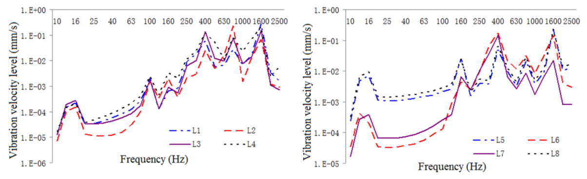
Figure 20One-third octave response curve of vibration intensity in typical housing parts under constrained damping condition.
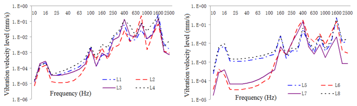
Figure 21One-third octave response curve of vibration intensity of typical housing parts under restrained damping and acoustic protection conditions.
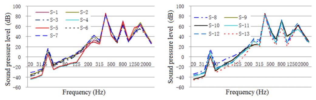
Figure 22One-third octave response curve of acoustic radiation from typical housing parts under original structural conditions.
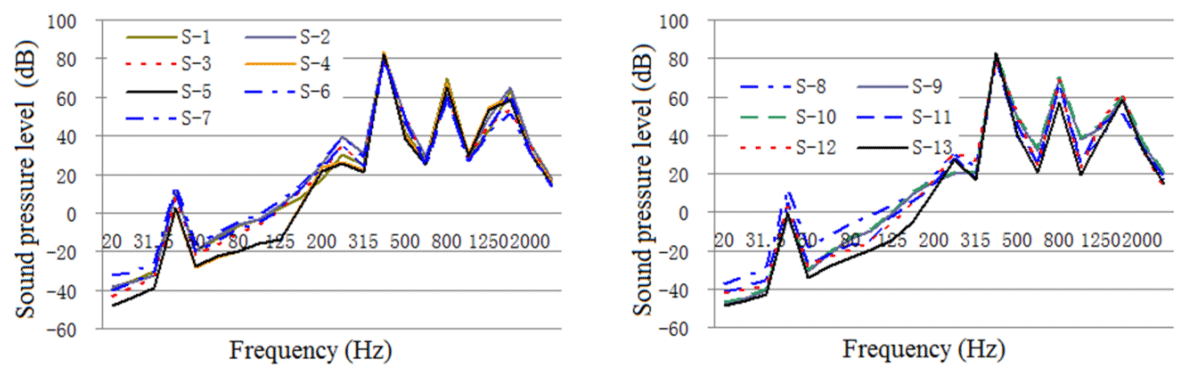
Figure 23One-third octave response curve of acoustic radiation from typical housing parts under constrained damping conditions.
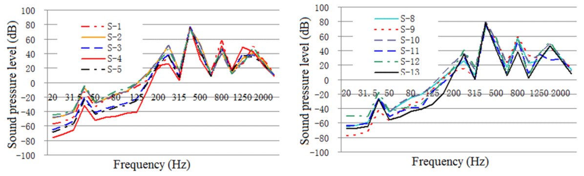
Figure 24One-third octave response curve of acoustic radiation from typical housing parts under restrained damping and acoustic protection conditions.
As illustrated in these figures, the damping layer, sound insulation layer, and sound absorption protection measures all decreased the vibration and noise levels of the housing structure. Vibration acceleration, vibration velocity, and radiation noise of the housing structure were reduced by 4–6 dB, 4–7 dB, and 7–10 dBA, respectively, where the effect of the constrained damping layer on the vibration acceleration and vibration intensity of the housing structure was between 4 and 6 dB. The influence of the restrained damping layer on the sound radiation housing was between 7 and 10 dBA. Protective measures such as absorption and isolation of sound had little effect on the vibration of the housing structure, and its effect on sound radiation housing was between 4 and 5 dBA.
Before the housing structure was acoustically treated, the sound pressure emitted from the backend panel and the small circumferential plate of each part of the housing was relatively large, which is the dominant component of the acoustics. Therefore, in practical applications, the vibration and acoustics should be controlled. In the following section, the optimal design of the housing structure of a PGR with low acoustics is detailed.
The input characteristics of the housing structure should be presented in the dynamic response analysis. In this section, the excitation force is used as input to the frequency domain by a fast Fourier transform, and the frequency spectrum characteristics of the meshing frequency and harmonic frequency are analyzed in detail. The excitation force in the frequency domain is used as an input parameter to analyze the harmonic response of the housing.
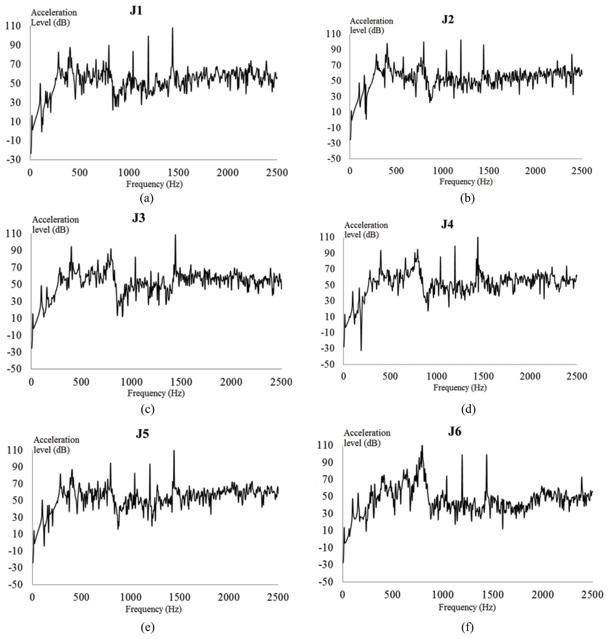
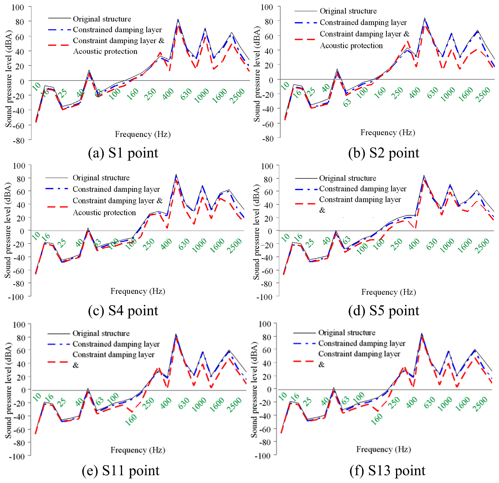
Figure 25Vibration acceleration level of each check point on the gear housing: vibration acceleration levels of check points (a) 1, (b) 2, (c) 3, (d) 4, (e) 5, and (f) 6.
The vibration acceleration response value and vibration acceleration level of each check point at the machine foot are shown in Fig. 25. In the figure, the vibration acceleration level curves represent each check point with acoustic protection and damping materials for reference. Compared with the naked housing structure of the PGR housing, the protected housing exhibits evident wave peaks in the acceleration response curves around the excitation frequencies of 400, 800, and 1440 Hz. Because the magnitude of the excitation force of the housing structure at this frequency was large, the response value of the housing structure was also the largest.
Correspondingly, the vibration response acceleration of the housing at a typical excitation frequency is considered under the action of the actual excitation load. Combined with the actual working conditions, a constrained damping layer is adopted for the housing structure. Based on the analysis of the dynamic characteristics, vibration transfer characteristics, and radiation noise characteristics of the housing structure, the structures of the frontend and backend plates, upper housing, and upper cover of the PGR housing are weaker.
Therefore, each part is thickened by 10 mm without changing the structural form. Then, the FEA model of the modified housing is reconstructed. Through the theory of the modal loss factor calculation for the constrained damping layer, the composite loss factor of the housing with the constrained damping layer is η=0.012. The vibration acceleration response of the building structure under the action of a practical excitation constrained damping layer is shown in Fig. 26.
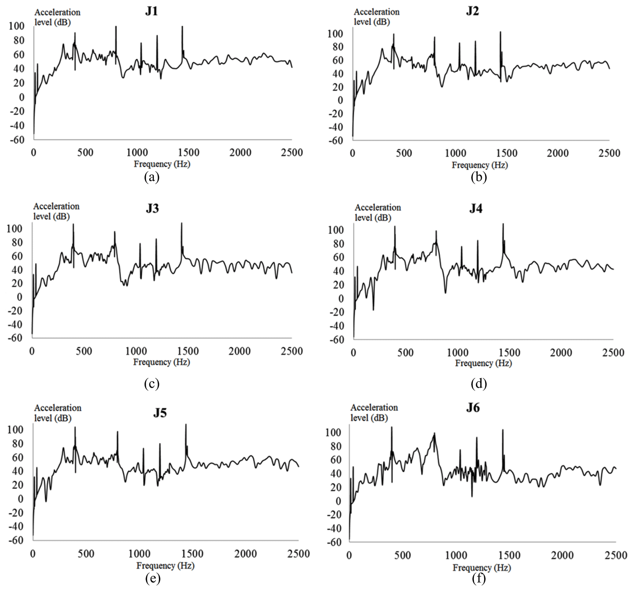
Figure 26Vibration acceleration of each check point considering the constrained damping layer (CDL): vibration accelerations of check points (a) 1, (b) 2, (c) 3, (d) 4, (e) 5, and (f) 6.
As illustrated in Fig. 26, the vibration response curve of the additional constrained damping layer was consistent with that of the unconstrained damping layer. The acceleration level of each test point was not more than 105 dB in the frequency domain. Moreover, the peaks of the acceleration response curve appeared at 399, 797, and 1439 Hz. These results show that the constrained damping layer will only affect the acceleration response of the housing structure near 400, 800, and 1440 Hz, but it will not affect the change of the acceleration curve at other frequencies.
Comparisons of vibration acceleration level, vibration intensity, and sound pressure level of typical housing parts before and after damping and acoustic protection vibration reduction and noise reduction are shown Figs. 27–29.
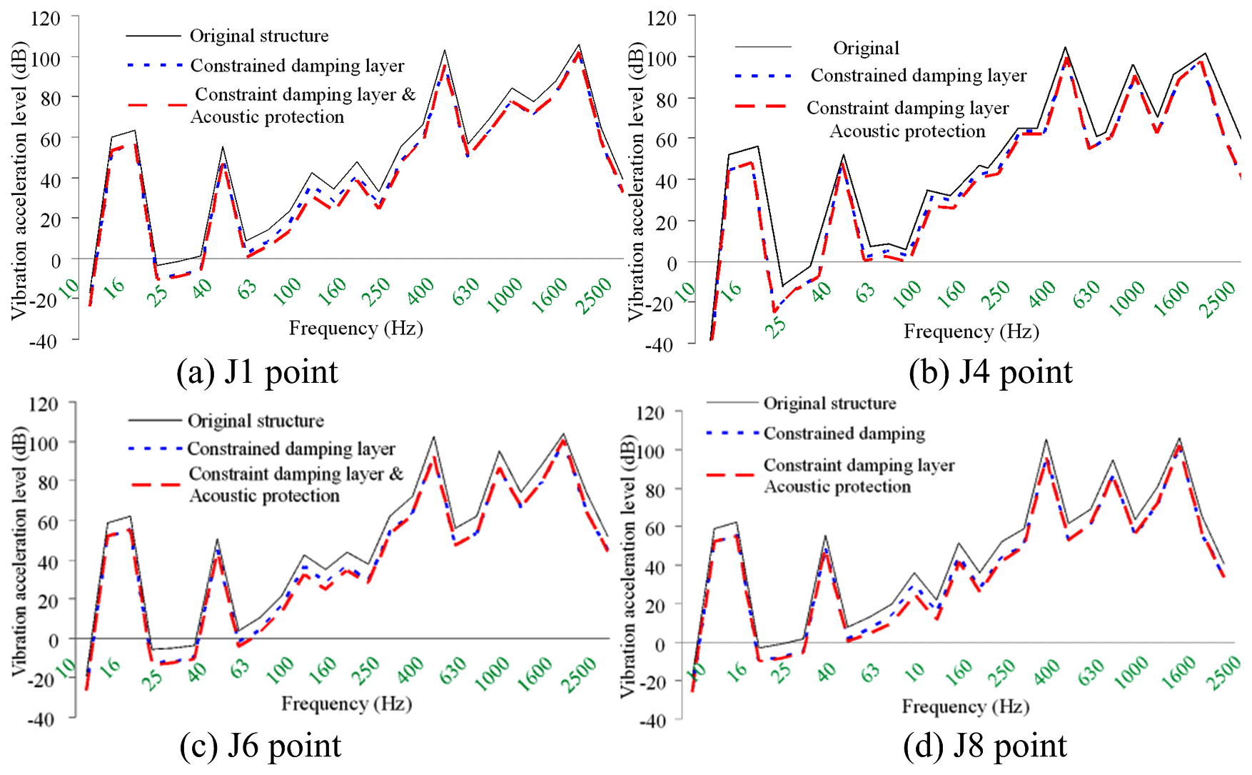
Figure 27EBS vibration acceleration level octave curves under typical auxiliary noise reduction measures.
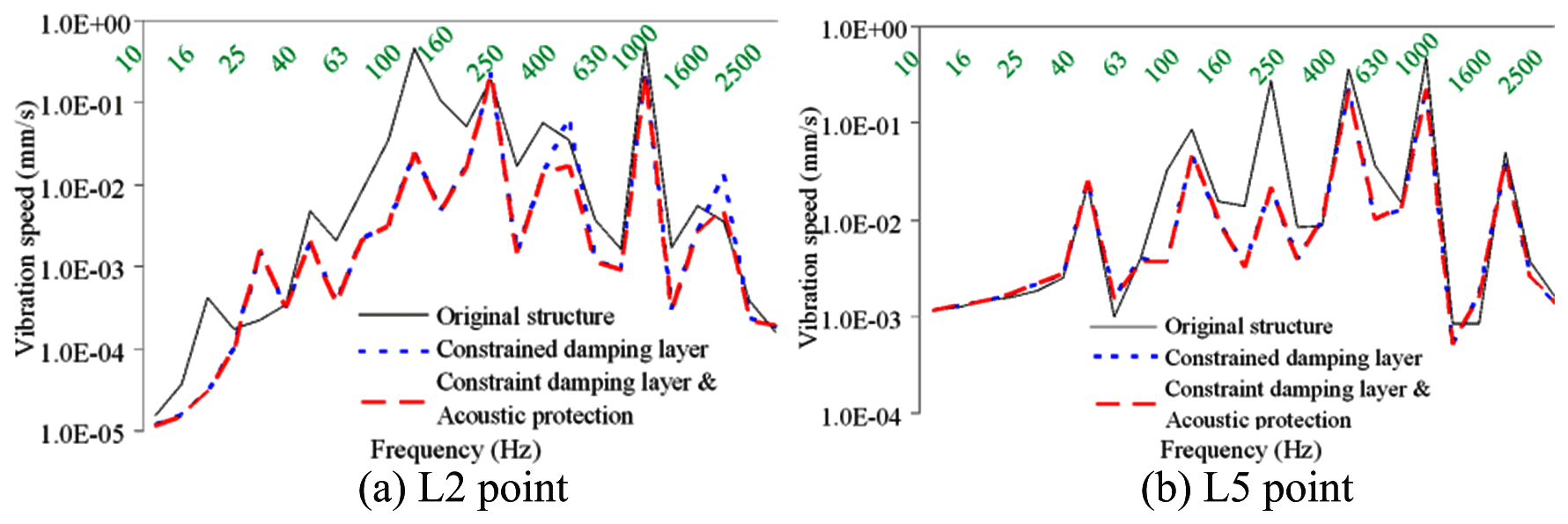
Figure 28EBS vibration intensity octave curves under typical auxiliary noise reduction measures.
It can be seen from the above figures that with the gear meshing force provided as input, the exterior body structure (EBS) vibration and sound radiation level is relatively high. Before the restraint damping and noise reduction measures are taken, the EBS vibration acceleration is between 107–110 dB, and the EBS vibration velocity is 0.4–0.55 mm s−1, EBS radiation noise is around 85 dBA, and when the constrained damping layer structure is adopted, considering the stiffness and damping effect of the constrained damping layer, EBS vibration and sound radiation are greatly reduced. After the constrained damping layer is adopted, the vibration acceleration of EBS drops to 102–105 dB, the vibration acceleration of EBS drops to 0.16–0.3 mm s−1, and the sound radiation of EBS drops to 80–83 dBA. After sound absorption and insulation protection measures are taken, the vibration level of EBS basically remains unchanged, and the sound radiation level has dropped greatly, the sound radiation of EBS drops to 73–78 dB.
It can be seen from the above figures that with the gear meshing force provided as input, the EBS vibration and sound radiation level is relatively high. Before the restraint damping and noise reduction measures are taken, the EBS vibration acceleration is between 107–110 dB, and the EBS vibration velocity is 0.4–0.55 mm s−1, EBS radiation noise is around 85 dBA, and when the constrained damping layer structure is adopted, considering the stiffness and damping effect of the constrained damping layer, EBS vibration and sound radiation are greatly reduced. After the constrained damping layer is adopted, the vibration acceleration of EBS drops to 102–105 dB, the vibration acceleration of EBS drops to 0.16–0.3 mm s−1, and the sound radiation of EBS drops to 80–83 dBA. After sound absorption and insulation protection measures are taken, the vibration level of EBS basically remains unchanged, and the sound radiation level has dropped greatly, the sound radiation of EBS drops to 73–78 dB.
In this paper, the structural–acoustic coupled vibration and noise analysis model of PGR housing was proposed through numerical analysis. The optimal design of the housing structure and the vibration noise characteristics were analyzed in detail, and the effects of auxiliary vibration absorption and noise reduction on the evaluation were verified. This study draws the following conclusions.
- 1.
Based on the optimized design and vibration noise characteristics from the housing structure analysis, the following conclusions were drawn:
- 1.1
The input and output end plates of the housing structure were weak relative to the circumferential stiffness. Considering the influence of housing shafting and other factors, strengthening the end structure cannot effectively improve the dynamic characteristics of the end part of the housing.
- 1.2
The housing structure had strong vibration line spectrum near the meshing frequencies of 399, 797, and 1439 Hz, and the vibration modes were the most intensive, which is the focus of the optimization of the housing dynamic characteristics.
- 1.1
- 2.
Based on the results of the analysis of the housing, structural damping vibration absorption and acoustic protection design of the housing are as follows:
- 2.1
When the constrained damping measures for vibration absorption and noise reduction housing were not adopted, the structural vibration acceleration was between 107 and 110 dB, the vibration velocity was between 0.4 and 0.55 mm s−1, and the radiated noise was approximately 85 dBA.
- 2.2
The implementation of the measures starkly decreased the vibration and sound radiation housing. The measures lead to the structural vibration acceleration plummeting to 102–105 dB, vibration velocity to 0.16–0.30 mm s−1, and radiated noise to 80–83 dBA.
- 2.3
Even with the protective measures in place, the vibration level of the housing remained basically unchanged, but the sound radiation of the housing structure decreased to 73–78 dB.
- 2.1
- 3.
After adopting the auxiliary measures of damping vibration reduction and sound insulation protection, the vibration acceleration, vibration velocity, and radiation noise of the housing structure were reduced by 4–6, 4–7, and 7–10 dBA, respectively.
The data used in this paper can be provided by the corresponding authors upon request.
For this article, LJ completed the overall writing of the thesis. JS completed the preliminary review of the paper. XW, as the first corresponding author, completed the main work of thesis review and proofreading. YW, as the second corresponding author, completed the main work of the paper data simulation and English editing. BF completed the literature review of the paper.
The authors declare that they have no conflict of interest.
The authors would like to thank the Northeast Forestry University (NEFU), Heilongjiang Institute of Technology (HLJIT), and the Harbin Institute of Technology (HIT) for their support.
The research topic was supported by the Doctoral Research Startup Foundation Project of Heilongjiang Institute of Technology (grant no. 2020BJ06, Yongmei Wang, HLJIT), the Natural Science Foundation Project of Heilongjiang Province (grant no. LH2019E114, Baixue Fu, HLJIT), the Basic Scientific Research Business Expenses (Innovation Team Category) Project of Heilongjiang Institute of Engineering (grant no. 2020CX02, Baixue Fu, HLJIT), the Special Project for Double First-Class-Cultivation of Innovative Talents (grant no. 000/41113102, Jiafu Ruan, NEFU), the Special Scientific Research Funds for Forest Non-profit Industry (grant no. 201504508), the Youth Science Fund of Heilongjiang Institute of Technology (grant no. 2015QJ02), and the Fundamental Research Funds for the Central Universities (grant no. 2572016CB15).
This paper was edited by Hui Ma and reviewed by two anonymous referees.
Acri, A., Nijman, E., Conrado, E., and Offner, G.: Experimental structure-borne energy flow contribution analysis for vibro-acoustic source ranking, Mech. Syst. Signal Pr., 115, 753–768, https://doi.org/10.1016/j.ymssp.2018.06.050, 2019.
Arasan, U., Marchetti, F., Chevillotte, F., Tanner, G., Chronopoulos, D., and Gourdon, E.: On the accuracy limits of plate theories for vibro-acoustic predictions, J. Sound Vib., 493, 115848, https://doi.org/10.1016/j.jsv.2020.115848, 2021.
Berry, A., Robin, O., and Pierron, F.: Identification of dynamic loading on a bending plate using the virtual fields method, J. Sound Vib., 333, 7151–7164, https://doi.org/10.1016/j.jsv.2014.08.038, 2014.
Bi, S. F., Ouisse, M., Foltête, E., and Jund, A.: Virtual decoupling of vibroacoustical systems, J. Sound Vib., 401, 169–189, https://doi.org/10.1016/j.jsv.2017.04.040, 2017.
Dai, H., Long, X. H., Chen, F., and Bian, J.: Experimental investigation of the ring-planet gear meshing forces identification, J. Sound Vib., 493, 115844, https://doi.org/10.1016/j.jsv.2020.115844, 2021.
Daneshjou, K., Talebitooti, R., and Kornokar, M.: Vibroacoustic study on a multilayered functionally graded cylindrical shell with poroelastic core and bonded-unbonded configuration, J. Sound Vib., 393, 157–175, https://doi.org/10.1016/j.jsv.2017.01.001, 2017.
Ege, K., Roozen, N. B., Leclère, Q., and Rinaldi, R. G.: Assessment of the apparent bending stiffness and damping of multilayer plates; modelling and experiment, J. Sound Vib., 426, 129–149, https://doi.org/10.1016/j.jsv.2018.04.013, 2018.
Garambois, P., Donnard, G., Rigaud, E., and Perret-Liaudet, J.: Multiphysics coupling between periodic gear mesh excitation and input/output fluctuating torques: Application to a roots vacuum pump, J. Sound Vib., 405, 158–174, https://doi.org/10.1016/j.jsv.2017.05.043, 2017.
Guo, Y., Eritenel, T., Ericson, T. M., and Parker, R. G.: Vibro-acoustic propagation of gear dynamics in a gear-bearing-housing system, J. Sound Vib., 333, 5762–5785, https://doi.org/10.1016/j.jsv.2014.05.055, 2014.
Kosała, K.: Calculation models for analysing the sound insulating properties of homogeneous single baffles used in vibroacoustic protection, Appl. Acoust., 146, 108–117, 2019.
Hu, W. G., Liu, Z. M., Liu, D. K., and Hai, X.: Fatigue failure analysis of high speed train gearbox housings, Eng. Fail. Anal., 73, 57–71, https://doi.org/10.1016/j.engfailanal.2016.12.008, 2017.
Hwang, H. D., Maxit, L., Ege, K., Gerges, Y., and Guyader, J.-L.: SmEdA vibro-acoustic modelling in the mid-frequency range including the effect of dissipative treatments, J. Sound Vib., 393, 187–215, https://doi.org/10.1016/j.jsv.2017.01.024, 2017.
Li, Y. Z., Ding, K., He, G. L., and Yang, X. Q.: Vibration modulation sidebands mechanisms of equally-spaced planetary gear train with a floating sun gear, Mech. Syst. Signal Pr., 129, 70–90, https://doi.org/10.1016/j.ymssp.2019.04.026, 2019.
Liang, X., Zuo, M. J., and Feng, Z.: Dynamic modeling of gearbox faults: A review, Mech. Syst. Signal Pr., 98, 852–876, https://doi.org/10.1016/j.ymssp.2017.05.024, 2018.
Lin, T. L. and Zhang, K.: An analytical study of the free and forced vibration response of a ribbed plate with free boundary conditions, J. Sound Vib., 422, 15–33, https://doi.org/10.1016/j.jsv.2018.02.020, 2018.
Marchetti, F., Ege, K., Leclère, Q., and Roozen, N. B.: On the structural dynamics of laminated composite plates and sandwich structures; a new perspective on damping identification, J. Sound Vib., 474, 115256, https://doi.org/10.1016/j.jsv.2020.115256, 2020.
Mironova, T. B., Prokofiev, A. B., and Sverbilov, V. Y.: The Finite Element Technique for Modelling of Pipe System Vibroacoustical Characteristics, Procedia Engineer., 176, 681–688, https://doi.org/10.1016/j.proeng.2017.02.313, 2017.
Morgado, T. L. M., Branco, C. M., and Infante, V.: A failure study of housing of the gearboxes of series 2600 locomotives of the Portuguese Railway Company, Eng. Fail. Anal., 15, 154–164, https://doi.org/10.1016/j.engfailanal.2006.11.052, 2008.
Renno, J. M. and Mace, B. R.: Calculating the forced response of cylinders and cylindrical shells using the wave and finite element method, J. Sound Vib., 333, 5340–5355, https://doi.org/10.1016/j.jsv.2014.04.042, 2014.
Rohan, E. and Lukeš, V.: Homogenization of the vibro-acoustic transmission on perforated plates, Appl. Math. Comput., 361, 821–845, https://doi.org/10.1016/j.amc.2019.06.005, 2019.
Rosa, S. D., Desmet, W., Ichchou, M., Ouisse, M., and Scarpa, F.: Vibroacoustics of periodic media: Multi-scale modelling and design of structures with improved vibroacoustic performance, Mech. Syst. Signal Pr., 142, 106870, https://doi.org/10.1016/j.ymssp.2020.106870, 2020.
Sánchez, M. B., Pleguezuelos, M., and Pedrero, J. I.: Approximate equations for the meshing stiffness and the load sharing ratio of spur gears including hertzian effects, Mech. Mach. Theory, 109, 231–249, https://doi.org/10.1016/j.mechmachtheory.2016.11.014, 2017.
Suslin, A. and Pilla, C.: Study of Loading in Point-involute Gears, Procedia Engineer., 176, 12–18, https://doi.org/10.1016/j.proeng.2017.02.267, 2017.
Tomilina, T. M.: New Approaches to Design of Structures with Required Vibroacoustic Properties, Procedia Engineer., 106, 350–353, https://doi.org/10.1016/j.proeng.2015.06.044, 2015.
Wang, Q. B., Chen, K. K., Zhao, B., Ma, H., and Kong, X. G.: An analytical-finite-element method for calculating mesh stiffness of spur gear pairs with complicated foundation and crack, Eng. Fail. Anal., 94, 339–353, https://doi.org/10.1016/j.engfailanal.2018.08.013, 2018a.
Wang, Q. B., Zhao, B., Fu, Y., Kong, X. G., and Ma, H.: An improved time-varying mesh stiffness model for helical gear pairs considering axial mesh force component, Mech. Syst. Signal Pr., 106, 413–429, https://doi.org/10.1016/j.ymssp.2018.01.012, 2018b.
Wang, Q. B., Xu, K., Huai, T. S., Ma, H., and Wang, K.: A mesh stiffness method using slice coupling for spur gear pairs with misalignment and lead crown relief, Appl. Math. Model., 90, 845–861. https://doi.org/10.1016/j.apm.2020.08.046, 2021.
Weis, P., Kučera, L'., Pecháč, P., and Močilan, M.: Modal Analysis of Gearbox Housing with Applied Load, Procedia Engineer., 192, 953–958, https://doi.org/10.1016/j.proeng.2017.06.164, 2017.
Wu, H., Wu, P. B., Li, F. S., Shi, H. L., and Xu, K.: Fatigue analysis of the gearbox housing in high-speed trains under wheel polygonization using a multibody dynamics algorithm, Eng. Fail. Anal., 100, 351–364, https://doi.org/10.1016/j.engfailanal.2019.02.058, 2019.
Yang, Y., Fenemore, C., Kingan, M. J., and Mace B. R.: Analysis of the vibroacoustic characteristics of cross laminated timber panels using a wave and finite element method, J. Sound Vib., 494, 115842, https://doi.org/10.1016/j.jsv.2020.115842, 2021.
Zhou, H. A., Zhao, Y. G., Wu, H. Y., and Meng, J. B.: The vibroacoustic analysis of periodic structure-stiffened plates, J. Sound Vib., 481, 115402, https://doi.org/10.1016/j.jsv.2020.115402, 2020.