the Creative Commons Attribution 4.0 License.
the Creative Commons Attribution 4.0 License.
 | 18 Feb 2021
Contact dynamics analysis of nutation drive with double circular-arc spiral bevel gear based on mathematical modeling and numerical simulation
Yujing Su
Ligang Yao
Jun Zhang
This paper describes a dynamic mathematical model of a new type two-stage nutation drive system with double circular-arc bevel gears. The dynamic displacement–vibration coupling model takes into account the gyro torque and side clearance of the nutating gear. A numerical analysis geometric model of the nutation drive system is developed. The geometric model considers the time-varying and contact deformation of nutation gear meshing. Subsequently, the model is analyzed using the ANSYS/LS-DYNA software, and the dynamic contact characteristics of the nutation gear are calculated. The simulation results revealed that the nutation transmission of the double circular-arc spiral bevel gear is reliable. Moreover, the mathematical verification showed that the simulation is feasible and accurate. The research has important significance for improving the tooth load capacity and transmission stability of nutation drives.
- Article
(4979 KB) - Full-text XML
- BibTeX
- EndNote


Nutation drive is a new type of motion that has been widely investigated in recent years. Compared to traditional gear drive, nutation gear transmission has characteristics such as high transmission efficiency, large transmission ratio, and stable transmission. Nutation drive has been widely used in mechanical transmission. Kemper (1981) proposed a nutation traction device. Green (2008) developed the kinematics model of a nutation mechanism and performed dynamic analysis. Uzuka et al. (2009) presented and optimized a new nutation pneumatic motor with small size and large torque based on the nutation principle (Oda et al., 2010). In pericyclic mechanical transmission, the tooth load capacity and nutation gear meshing efficiency are investigated (Saribay and Bill, 2013). The kinematics, mechanical efficiency, and dynamic balance of nutation drive have been analyzed based on a multi-body model (Fanghella et al., 2015, 2016). Yao et al. (2010) designed a double circular-arc spiral bevel gear nutation transmission based on the spiral theory, and Hong et al. (2015) developed a kinematics model of nutation drive. To dynamically analyze nutation drive, Su et al. (2019) conducted nonlinear finite-element analysis on the dynamic meshing of a double circular-arc spiral bevel gear nutation drive. Lin et al. (2020) developed a dynamic model of double-sided meshing nutation drive with double circular-arc spiral bevel gears and analyzed its corresponding vibration modes. Concerning magnetic nutation transmission, Huang et al. (2017) built a magnetic nutation gear reducer model and analyzed its torque, while Lou and Yao (2020) established a mathematical model of magnetic nutation transmission and performed numerical simulations.
With respect to gear meshing contact, the development of integrated computer finite-element analysis (FEA) programs promotes the contact analysis of spiral bevel gear transmission (Simon, 2007). Lin et al. (2007) demonstrated a finite-element method for 3D static and dynamic contact/impact analysis of gear drives, where the dynamic response of the gear can be obtained by performing FEA. Under nutation gear mesh contact, the nutation gear is subjected to large loads and impacts, and the contact dynamic characteristics affect its transmission performance. However, the main body of research focuses on the structural design, vibration analysis, and static analysis of nutation gears, with the research on dynamic contact analysis being relatively limited.
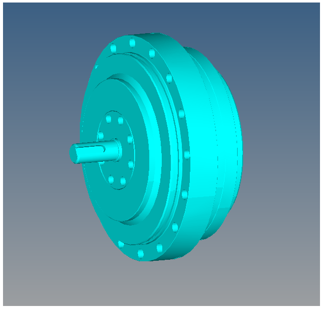
In this paper, a two-stage double circular spiral bevel gear nutation reducer (Fig. 1) was investigated, and a multi-DOF coupling vibration dynamic model of double circular spiral bevel gear nutation transmission was established using the concentrated parameter method. The dynamic model takes into account the nutation gyro moment, meshing transmission error, and gear tooth side clearance. In this paper, the nonlinear FEA method is used for the numerical simulations, the contact deformation and time-varying meshing are taken into consideration, and the dynamics and contact characteristics during meshing are solved simultaneously. The dynamic contact meshing stress and strain, vibration displacement, vibration speed, and dynamic meshing force of the nutation drive are determined, which are important for the reduction of nutation drive vibration and shock as well as for improving the transmission performance.
2.1 Mathematical model
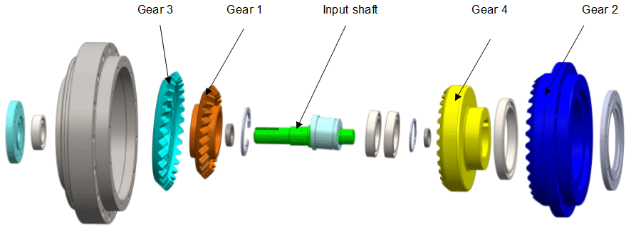
A cross section of the two-stage nutation drive reducer structure is shown in Fig. 2. Gear 1 and gear 3 are external bevel gears, which are fastened by screws to perform nutation movement. Gear 2 and gear 4 are internal bevel gears. The rotation speed is transmitted to gear 1 and gear 3 by the input shaft. Gear 1 meshes with gear 4 and gear 3 meshes with gear 2. Gear 2 is fixed to the frame, and torque is output from gear 4. In this paper, gear 1 and gear 4 are called nutation external bevel gear and output internal bevel gear, respectively.

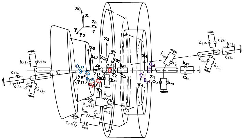
Figure 3 illustrates the dynamic model of the two-stage nutation gear system, where O–xyz represents the global coordinate system, O–x0y0z0 is a nutation coordinate system, and origin O is on the conical point of the nutation external bevel gear. The gears are simulated by the lumped parameter method, the axle is simulated by mass-free rigid elements, and the bearing is elastically supported by a spring and a damper. Subscripts i=1, 3, 2 and 4 represent the external bevel gears 1 and 3 and the internal bevel gears 2 and 4.
2.2 Dynamic differential equations
In Fig. 4, the force on the nutation external bevel gear is analyzed. The meshing forces on the nutation bevel gear along each coordinate direction are expressed as Eq. (1):
where j=1, 2 represents the gear pairs 1 and 2, kmj(t) represents the time-varying meshing stiffness of the gear pairs, and f(λnj) is the clearance function.

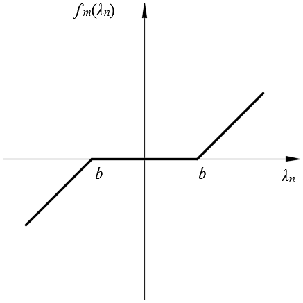
The backlash can be expressed as
where bi (i=1, 2) is the tooth backlash of each gear pair, and λni is the dynamic relative displacement between the meshing gear teeth due to vibration and error during the bevel gear meshing process. The backlash function is shown in Fig. 5.
According to the Hamilton principle, the dynamic differential equations of the two-stage nutation drive system can be obtained as follows.
Subsequently, the dynamic differential equation of the nutation system can be written as
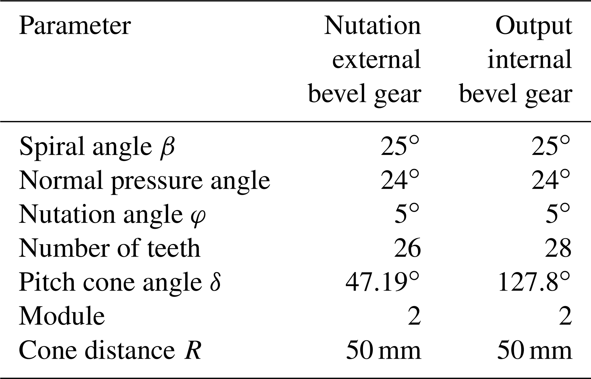
The dynamic differential equation of the nutation system (Eq. 4) can be solved numerically. The geometric model was developed in the HYPERMESH software (Fig. 6) and numerically solved using the ANSYS/LS-DYNA software. The gear parameters are shown in Table 1. In the two-stage nutation drive system, the nutation external and output internal bevel gears are the main transmission components, which were set as elastic bodies, the material of the double circular-arc spiral bevel gear was defined as structural steel with an elastic modulus E of 206 GPa, a Poisson ratio of 0.29, and a mass density of 7850 kg m−3, while the remaining components were set as rigid bodies. To obtain a higher accuracy, eight-node hexahedral elements were used to mesh the external nutation and output internal bevel gears. The meshing result, consisting of a total of 116 704 elements and 140 126 nodes, is shown in Fig. 7.

4.1 Stress distribution
In order to investigate the tooth surface meshing condition, the nutation drive system was simulated under an input speed of 1050 r min−1, and the stress distributions on the nutation external bevel (gear 1) and output internal bevel gears (gear 4) are shown in Fig. 8. In the figure, it can be seen that the stress was distributed along the tooth line, and during transmission, there were three teeth under stress, which improved the stability of the transmission.

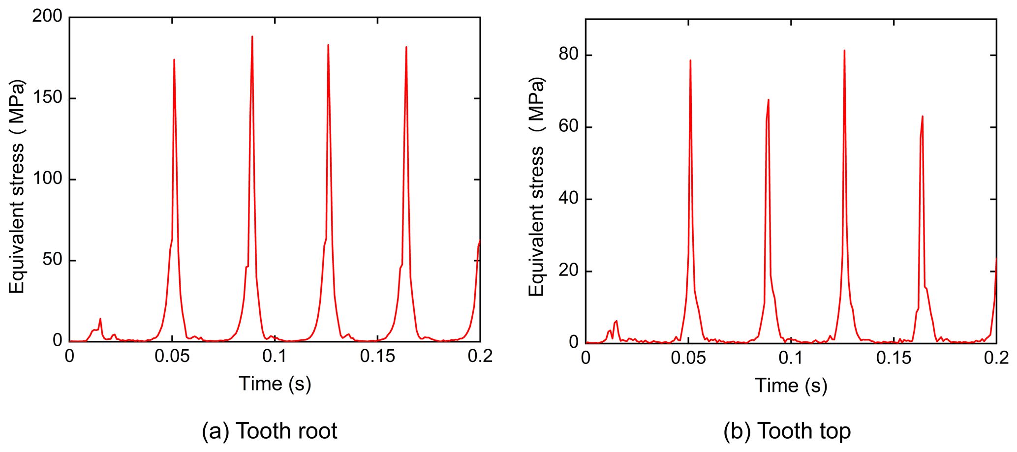
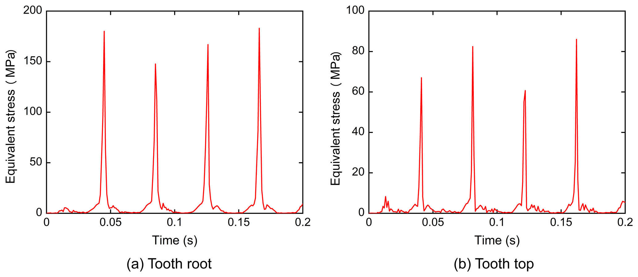
4.2 Equivalent stress
The plots of the equivalent stress over time of the nutation gear are shown in Figs. 9 and 10. The input speed was set as 1050 r min−1 and the simulation time was 0.2 s. According to the results, the equivalent stress on the gear tooth root was about 180 MPa and that on the tooth top was about 70 MPa. When the nutation gears meshed, the equivalent stress at the tooth top was smaller than that at the tooth root, exhibiting a periodic change.
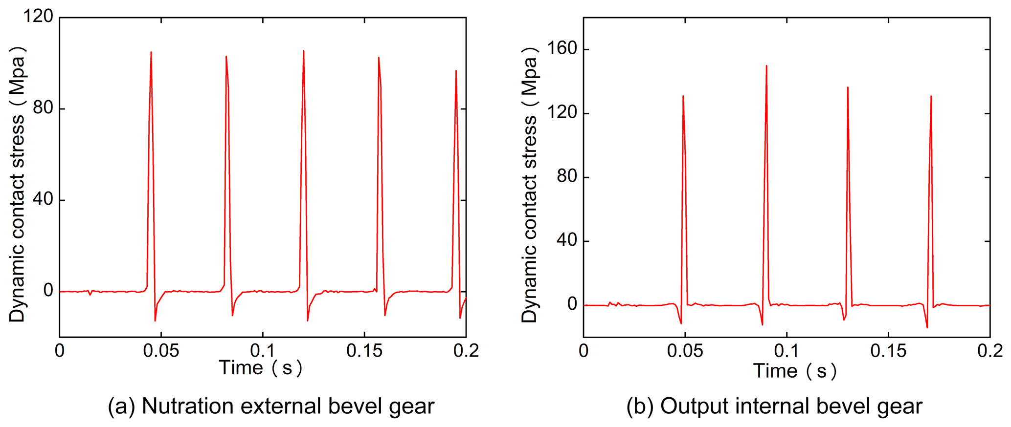
4.3 Contact stress
Due to the existence of the nutation angle, the nutation gear is periodically impacted during transmission. The dynamic meshing contact stress (impact stress) of the nutation drive is plotted in Fig. 11: it can be seen that the impact on the gear is periodic.
4.4 Vibration displacement
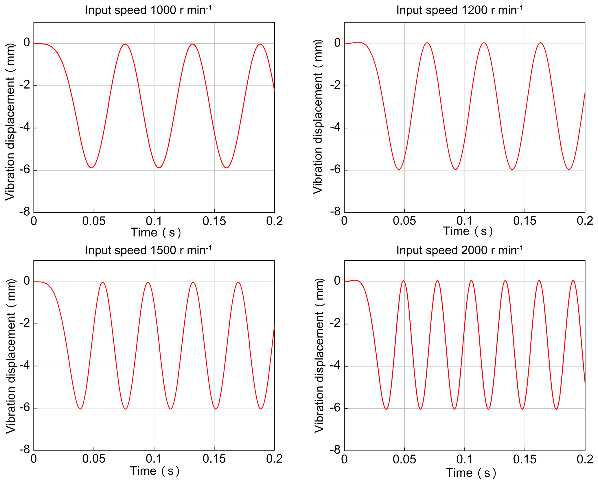
Considering that the nutation transmission gear produces vibration and shock during meshing, the vibration displacement of the nutation external bevel was investigated. The input speed was set to 1000, 1200, 1500, and 2000 r min−1. A point at the center of the tooth with equal distance from the tooth root and the tooth top was selected as the sampling point. Based on the different input speeds, the displacement of the nutation gear along the z axis during transmission was analyzed. It is shown as Fig. 12. According to Fig. 12, the z-axis direction vibration displacement amplitude at different speeds was stable, while the vibration displacement frequency increased with increasing input speed.

4.5 Vibration velocity
Figure 13 shows the vibration velocity of the nutation external bevel gear over time under different input speeds. Again, the sampling point was at the center of the tooth with equal distance from the tooth root and the tooth top. According to the results, the dynamic response of the vibration velocity increased with increasing input speed; consequently, the vibration amplitude in the nutation system was increased.
4.6 Dynamic meshing force
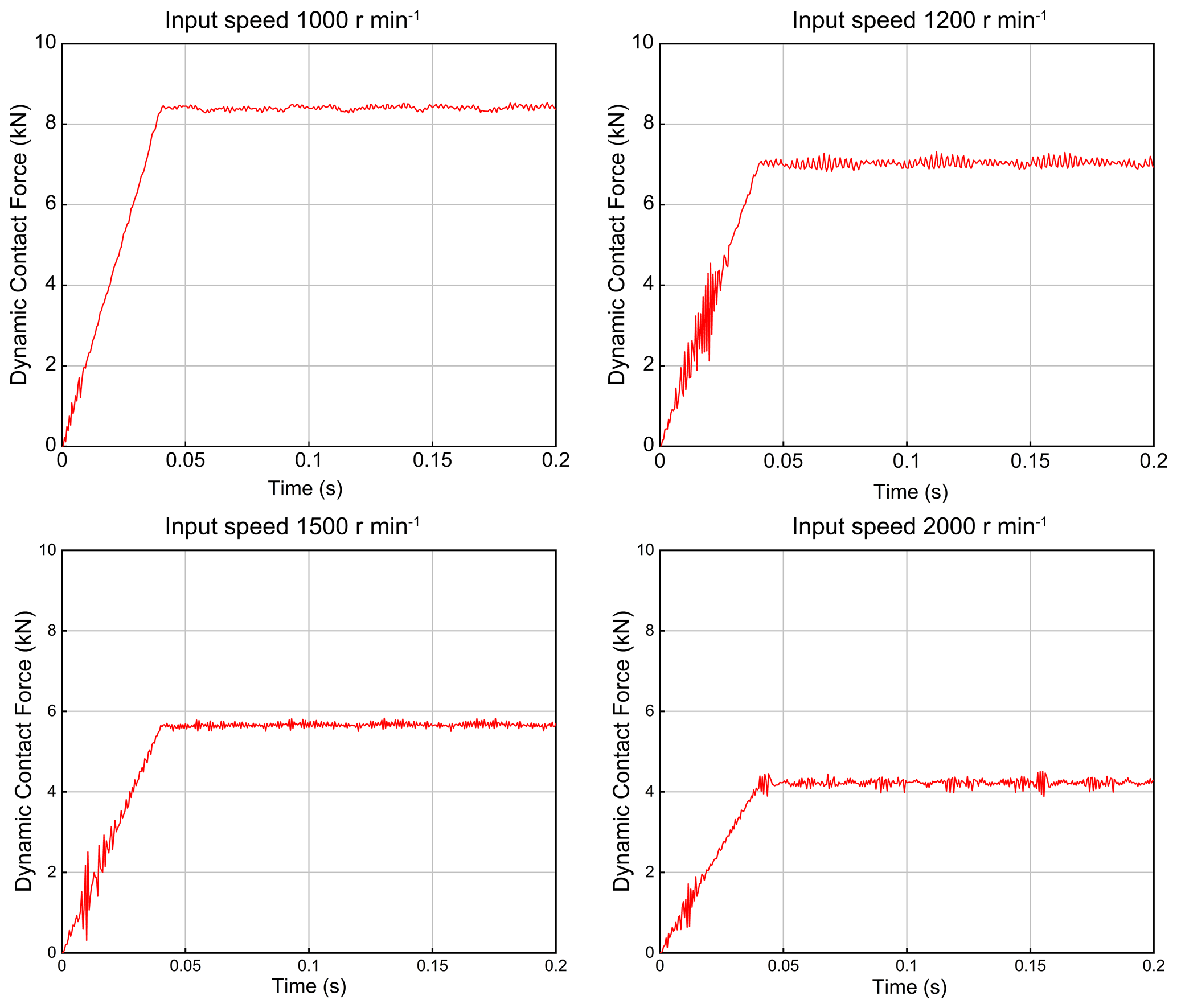
The dynamic meshing force generated between the input external bevel gear and the output internal gear under different input speeds is presented in Fig. 14. It can be seen that when the load of the reducer was empty, the dynamic meshing force changed due to the different input speeds and the corresponding contact meshing force decreased significantly with increasing input speed.
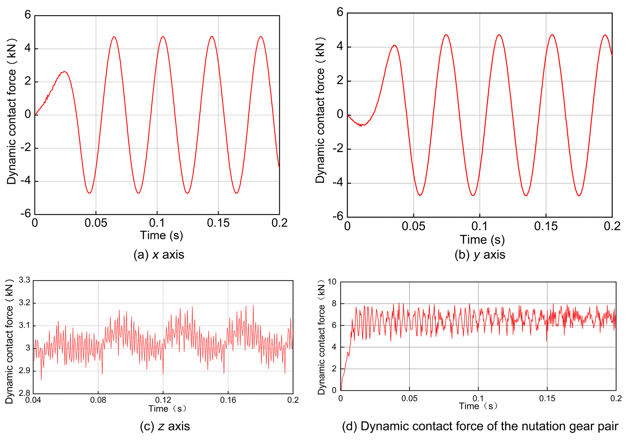
The gear dynamic meshing force in the x, y, and z directions under an input speed of 1050 r min−1 is shown in Fig. 15. The meshing force in the x and y directions is shown in Fig. 15a–b, respectively. The dynamic meshing force along the z axis is shown in Fig. 15c. The meshing force between the input external bevel gear and the output internal gear is presented in Fig. 15d, according to which the average meshing force was 6523.12∘ N.
When the input speed is 1050 r min−1, the input torque T is 1.7×10⁵ N, and according to the load, the mechanical efficiency η is set as 0.85; then, the torque of the output bevel gear T4 is
Then, the gear circumferential force can be expressed as
Subsequently, the meshing force can be represented as
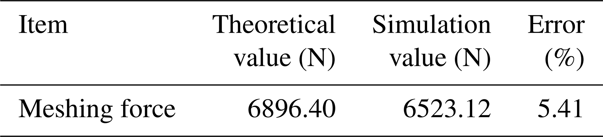
Based on the calculations, the theoretical value of the contact force of the nutation gear was 6896.40 N and the simulated one was 6523.12 N. According to Table 2, the error was 5.41 %, which is within a reasonable range.
A dynamic model of the nutation transmission system has been developed using the lumped parameter method. A FEA model of the double circular-arc spiral bevel gear nutation drive was built, which considered the nutation gear time-varying meshing and contact deformation. The geometric model of the nutation drive system was simulated using ANSYS/LS-DYNA, and the mathematical verification proved the accuracy of the model. Basic dynamic contact characteristics of double circular-arc spiral bevel gears, including dynamic contact stress and vibration displacement meshing force, have been obtained for the first time. The results revealed that the overall transmission of the nutation reducer is stable, and the meshing force of the double circular-arc spiral bevel nutation gear is between 4 and 9 kN. Through the comparison under different input speeds, it was found that, at high speeds, the dynamic response vibration frequency increases, while the contact meshing force decreases. These features are conducive to future structural optimization and performance improvement.
| mi | Equivalent concentrated mass of each gear |
| Bearing stiffness | |
| Bearing damping | |
| rmi | Radius of the meshing point of the gear pair |
| Ji | The moment of inertia of each component |
| L01,L03 | Gyro torque generated by the nutation of two external bevel gears |
| u | System displacement |
| M | Mass matrix |
| C | The damping matrix |
| K | Stiffness matrix |
| Rt | Gear-meshing external load |
| Dijk | Strain condition |
| Lei | Element-equivalent length |
| Cr | Velocity of elastic material wave |
All data included in this study are available upon request by contact with the corresponding author.
LY proposed the idea and methodology; YS and JZ applied the methodology; YS conducted the simulations, surveyed the literature, and wrote the paper.
The authors declare that they have no conflict of interest.
This research has been supported by the National Science Foundation of China (grant nos. 51775114 and 51875105) and the Fujian Provincial Industrial Robot Basic Components Technology Research and Development Center, Fujian, PR China (grant no. 2014H21010011).
This research has been supported by the National Natural Science Foundation of China (grant nos. 51775114 and 51875105) and the Fujian Provincial Industrial Robot Basic Components Technology Research and Development Center (grant no. 2014H21010011).
This paper was edited by Dario Richiedei and reviewed by Luca Bruzzone and one anonymous referee.
Fanghella, P., Bruzzone, L., and Ellero, S.: Dynamic balancing of a nutating planetary bevel gear train, Mech. Mach. Sci., 25, 23–33, https://doi.org/10.1007/978-3-319-09858-6_3, 2015.
Fanghella, P., Bruzzone, L., and Ellero, S.: Kinematics, efficiency and dynamic balancing of aplanetary gear train based on nutating bevel gear, Mech. Based Des. Struc., 44, 72–85, https://doi.org/10.1080/15397734.2015.1047956, 2016.
Green, I.: On the kinematics and kinetics of mechanical seals, rotors, and wobbling bodies, Mech. Mach. Theory, 43, 909–917, https://doi.org/10.1016/j.mechmachtheory.2007.06.004, 2008.
Hong, J. L., Yao, L. G., Ji, W. T., and Huang, Z. P.: Kinematic modeling for the nutation drive based on screw theory, Proc. CIRP, 36, 123–128, https://doi.org/10.1016/j.procir.2015.06.103, 2015.
Huang, D. J., Yao, L. G., Li, W. J., and Zhang, J.: Design and realization of a novel magnetic nutation drive for industry robotic wrist reducer, Ind. Robot, 44, 58–63, https://doi.org/10.1108/IR-04-2016-0130, 2017.
Kemper, Y.: The nutating traction drive, J. Eng. P., 103, 154–157, https://doi.org/10.1115/1.3230688, 1981.
Lin, T. T., Ou, H. G., and Li, R. F.: A finite element method for 3D static and dynamic contact/impact analysis of gear drives, Comput. Method. Appl. M., 196, 1716–1728, https://doi.org/10.1016/j.cma.2006.09.014, 2007.
Lin, Z., Yao, L., and Xie, Z.: Dynamic modal analysis of double-sided meshing nutation drive with double circular arc spiral bevel gears, Mech. Sci., 11, 115–123, https://doi.org/10.5194/ms-11-115-2020, 2020.
Lou, M. Y. and Yao, L. G.: Mathematic Modelling and Numerical Analysis for a Novel Inner-Type Nutation Magnetic Drive, Energies, 13, 1346, https://doi.org/10.3390/en13061346, 2020.
Oda, S., Suzumori, K., Uzuka, K., and Enomoto, I.: Development of nutation motors (improvement of pneumatic nutation motor by optimizing diaphragm design), J. Mech. Sci. Technol., 24, 25–28, https://doi.org/10.1007/s12206-009-1157-y, 2010.
Saribay, Z. B. and Bill, R. C.: Design analysis of pericyclic mechanical transmission system, Mech. Mach. Theory, 61, 102–122, https://doi.org/10.1016/j.mechmachtheory.2012.10.007, 2013.
Simon, V.: Computer simulation of tooth contact analysis of mismatched spiral bevel gears, Mech. Mach. Theory, 42, 365–381, https://doi.org/10.1016/j.mechmachtheory.2006.02.010, 2007.
Su, Y. J., Yao, L. G., and Zhang, J.: Nonlinear Finite Element Simulation and Analysis of Double Circular Arc Spiral Bevel Gear Nutation Drive, in: ICIRA 2019, International Conference on Intelligent Robotics and Applications, edited by: Yu, H., Liu, J., Liu, L., Ju, Z., Liu, Y., and Zhou, D., Lecture Notes in Computer Science, Springer, Cham, Switzerland, 11740, 608–615, https://doi.org/10.1007/978-3-030-27526-6_53, 2019.
Uzuka, K., Enomoto, I., and Suzumori, K.: Comparative assessment of several nutation Motor Types, IEEE-ASME T. Mech., 14, 82–92, https://doi.org/10.1109/TMECH.2008.2004035, 2009.
Yao, L. G., Gu, B., Huang, S. J., Wei, G. W., and Dai, J. S.: Mathematical modeling and simulation of the external and internal double circular-arc spiral bevel gears for the nutation drive, J. Mech. Design, 132, 021008, https://doi.org/10.1115/1.4001003, 2010.
- Abstract
- Introduction
- Dynamic modeling of the nutation drive
- Computer simulation
- Simulation analysis of the nutation drive system
- Mathematical verification
- Conclusions
- Appendix A: Nomenclature
- Data availability
- Author contributions
- Competing interests
- Acknowledgements
- Financial support
- Review statement
- References