the Creative Commons Attribution 4.0 License.
the Creative Commons Attribution 4.0 License.
 | 09 Feb 2021
Relationship between shear strength and surface roughness of double-layered pipes by cold drawing
Moktan Ahn
Joonhong Park
Pipes applied to marine plants are used in deep-sea environments; therefore, they must be resistant to high pressure and corrosion. Because it is difficult to satisfy both of these factors in a single pipe, studies on a double-layered pipe are continuously being performed. An outer pipe should be made of carbon steel, with high pressure resistance, and an inner pipe should be made of stainless steel, with high corrosion resistance. A pipe formed by combining these two pipes is called a lined pipe. The shear strength of the lined pipe is an important factor because pipe cracking can occur due to stress concentration when two pipes are separated by bending or high pressure. Therefore, various processes have been applied to increase the shear strength. In this paper, we investigate the effect of the surface roughness of the bonding interface on the shear strength. Surface roughness is in units of micrometers, and it cannot be used for finite element method (FEM) analysis. Therefore, surface roughness should be converted into a friction coefficient to perform FEM analysis. The effect of surface roughness on shear strength was studied in the relationship between the results of pressure from FEM analysis and the shear strength test.
- Article
(4232 KB) - Full-text XML
- BibTeX
- EndNote


Pipes, as core parts of the plant industry, are being studied continuously, owing to increasing interest in the offshore plant industry. Because deep-sea resources are present in harsh environments and subjected to high pressure and corrosion, advanced technology is required to overcome them. Carbon steel and stainless steel are materials that have strength in harsh conditions. Carbon steel has excellent strength in pressure resistance according to the content of carbon and manganese, and the reason why stainless steel is resistant to corrosion is that chromium forms a protective film on the surface. However, in the offshore plant industry environment, both characteristics (high pressure and corrosion resistance) must be satisfied. It is difficult to satisfy performance with a single material.
In order to satisfy both characteristics with a single steel pipe, in the past, most pipes were made of stainless steel, but for pressure resistance, the pipe must be about 1.5 times thicker than carbon steel, which is very disadvantageous in terms of material cost. Therefore, lined pipes manufactured by bonding two tubes are in the spotlight. A lined pipe is a double-layered pipe that is formed by bonding two pipes into one pipe according to metal forming (Li et al., 2008; Akdesir et al., 2016). The inner pipe (stainless steel) is resistant to corrosion, and the outer pipe is resistant to the working fluid and external high pressure. The most important design factor of the lined pipe is the bonding strength between materials. Bonding strength is expressed as the shear strength at which two bonded materials are fractured by applying shear force. Insufficient bonding force between materials can lead to failure of bonding between materials in the presence of high pressure and the bending process and cracking due to stress concentration in the pipe (Vasilikis and Karamanos, 2012; Fu et al., 2016). Therefore, since the bonding strength is the most important research target in lined pipes, the study is mainly carried out through the roll bending forming process because the roll bending process can easily increase the reduction area of the main factors that affect the high bonding strength (Eizadjou et al., 2009; Hosseini and Manesh, 2015; Naseri et al., 2016; Akramifard et al., 2014; Jamaati and Toroghinejad, 2010; Eizadjou et al., 2008; Madaah-Hosseini and Kokabi, 2012; Rezaii et al., 2020). The roll bending process is as follows. First, two sheets are subjected to material bonding through the rolling process. Second, the sheet material is passed through a multi-stage roll bending machine to form the pipe shape. Finally, a jointed portion is produced through electric resistance welding (ERW). This is a multi-step process involving the pipe transfer process at each stage, which leads to poor mass productivity and the drawback of decreasing the strength of the welded portion. We attempt to overcome the drawbacks of the roll bending process by the drawing process.
In this study, unlike conventional studies that bond through metal forming where high pressure load is possible between two materials, we intend to investigate the bonding strength according to the change in surface roughness at the contact surface of the two materials and apply it to a drawing process in which a high pressure load is difficult. The inner pipe surfaces that came into contact with the outer pipe were treated with different grinder blades. We measured the surface roughness of the specimen, and the measured surface roughness was converted into a Coulomb friction coefficient. The converted Coulomb friction coefficient value was applied to the finite element method (FEM) analysis. The shear strength test of the specimens through a universal testing machine was conducted to compare the shear strength and normal pressure applied to the material undergoing FEM analysis. Based on this, the relationship between surface roughness and shear strength was investigated.
2.1 Drawing process of the double-layered pipe
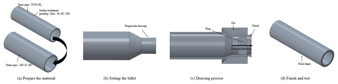
Before the drawing process, the contact surface between the two materials must be clean. Then, the surface of the inner pipe is processed through a grinder. The outer and inner pipes are lubricated that come into contact with the die and plug. If the lubricant is applied between the outer and inner pipes, it may contain impurities between the metal bonding. This adversely affects metal bonding. Therefore, no lubricant is applied between the outer and inner pipes. The inner pipe is inserted into the outer pipe, and it is mounted on the drawing machine. A plug is inserted into the pipe, and the front portion of the pipe is compressed through the compressor such that it can be coupled to the chuck. The chuck is pulled and passed through two pipes between the die and the plug to form one lined pipe. A schematic illustration of the fabrication of a lined pipe is shown in Fig. 1.
2.2 Double-layered pipe bonding mechanism
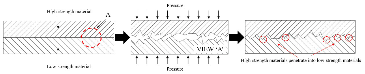
A schematic illustration of the bonding mechanism is presented in Fig. 2. In past research, many attempts have been made to explain the mechanism of the bonding process. Li et al. (2008) discovered the major bonding mechanism of double-layered pipes. When sufficient normal pressure is applied between the two metals' surfaces, the metal which is relatively high-strength penetrates into the cracks of the low-strength metal surface, and mechanical bonding is achieved. Also an important parameter is the surface roughness of the contact surface. Surface roughness affects the acceleration of material penetration of the contact surface. Therefore, the normal pressure applied between the two metals and the surface roughness are the most important parameters of the bonding mechanism.
2.3 Method of surface treatment
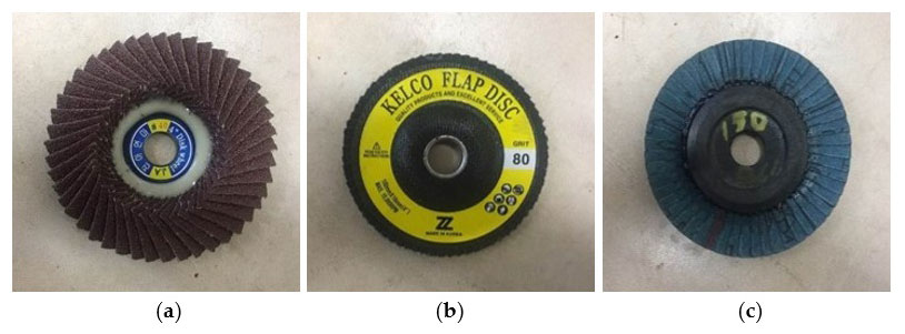
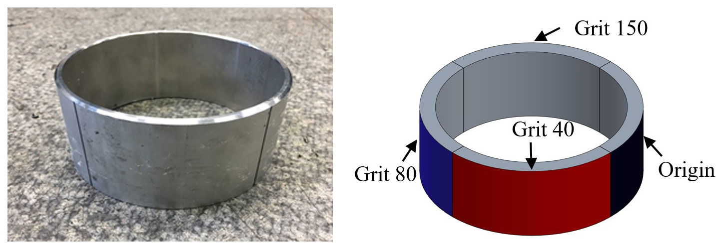
The different blades are shown in Fig. 3. The roughness of the blades is expressed in units of grit. Units of grit mean the particle size of the grinder blade, and the particle size refers to the number of particles per unit area. Therefore, when surface treatment is performed with a high grit number blade, the surface becomes smooth; conversely, when it is low, the surface is roughly treated. In order to analyze the bonding properties according to the surface roughness, the grit value was surface-treated with grit blades of 40, 80 and 150, whereby grit values were increased by about 2 times from 40. Grinding was performed using three grinder blades on the contact surface of the outer pipe and inner pipe, and the surface-treated inner pipe was made into a specimen using a laser cutting machine, shown in Fig. 4.
2.4 Relationship of surface roughness and friction coefficient
The relationship between the friction coefficient and the surface roughness was verified by Lee et al. (2002). The experiment by Lee et al. (2002) was conducted to investigate the relationship between the friction coefficient and surface roughness of various lubricants. The result of curve fitting the data is expressed in the following equation:
where λ is the surface roughness, and μ is the Coulomb friction coefficient.
In this paper, the surface roughness of each specimen is measured by applying three different surface roughness according to grinder blades, and the friction coefficient value was calculated by substituting the measured surface roughness into Eq. (1).
3.1 Surface roughness measurement
To confirm the change in the surface roughness through surface treatment using the grinding, the specimens were divided into four sections (grit 40, 80, 150 and virgin). Surface roughness was measured four times at five different points (A, B, C, D, E). The surface roughness was measured using a surface profile tester (DIAVITE DH-6), as shown in Fig. 5.

3.2 Result of surface roughness
The raw data of surface roughness are subjected to surface treatment according to grinder blades with different roughness, as shown in Fig. 6. A total of four surface roughness measurement values were taken from the measurement points (A, B, C, D, and E) of the surface-treated specimens, and 20 measurements were made. The results of surface roughness measured at each point are summarized as shown in Table 1.
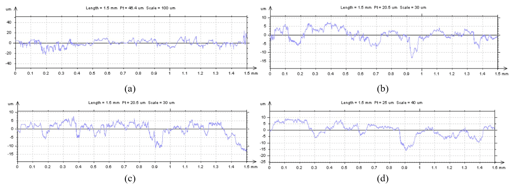
Figure 6Result of the surface roughness using the DIAVITE DH-6. (a) Raw data of surface-treated specimen using grit 40 grinder blades. (b) Raw data of surface-treated specimen using grit 80 grinder blades. (c) Raw data of surface-treated specimen using grit 150 grinder blades. (d) Raw data of virgin specimen.

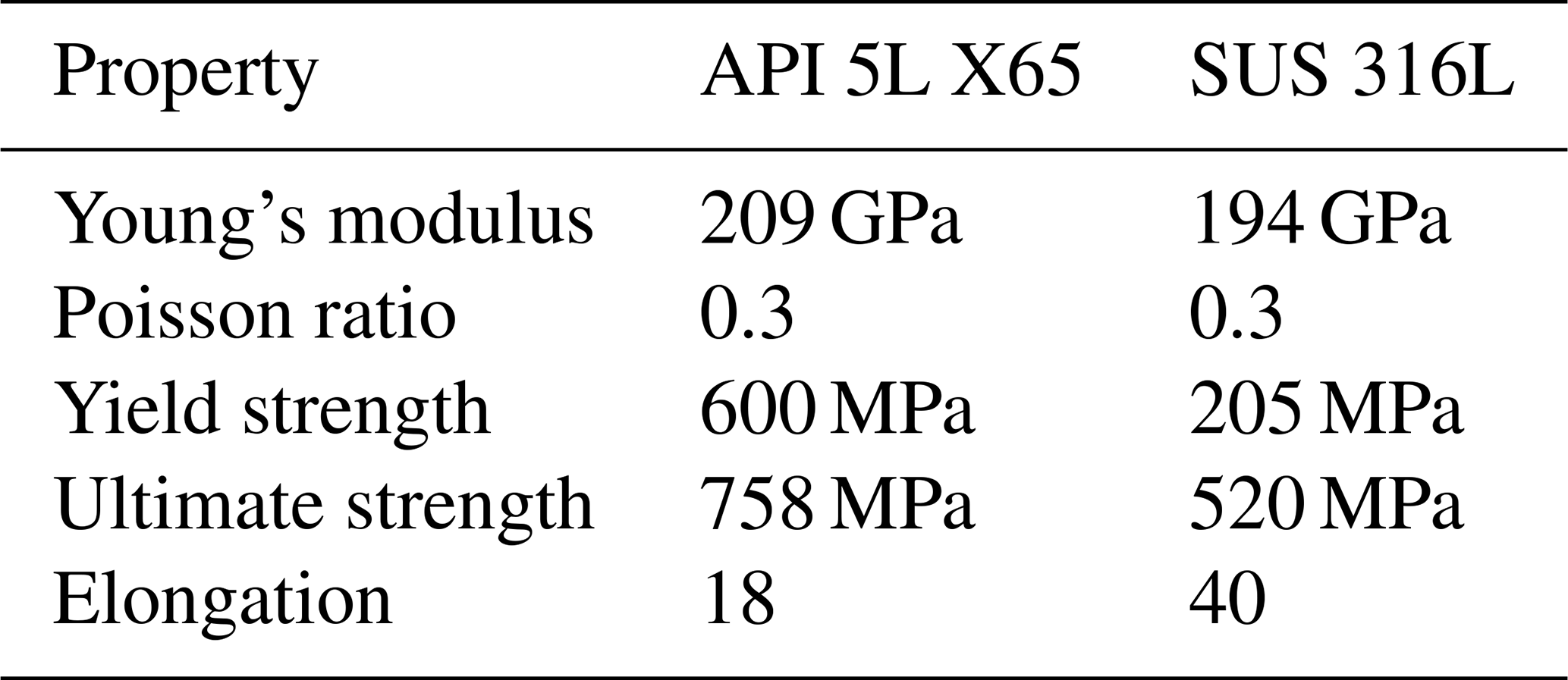
In order to analyze the effect of surface roughness on shear strength, surface roughness was converted into a friction coefficient and applied in FEM analysis. DEFORM, which is software used mainly in plastic processing, was used, and the springback effect was neglected. The drawing process minimized FEM analysis time using a two-dimensional (2D) axisymmetry model, and a schematic view of the drawing process is shown in Fig. 7. The inner and outer pipes are plastic bodies; the inner pipe is divided into 2918 elements, and the outer pipe is divided into 3898. The die, plug and chuck are rigid bodies. The drawing speed was set to 400 mm s−1 according to the general cold drawing process standard. The friction coefficient between the billet (inner, outer pipe) and drawing the die and plug is set as 0.12 because dry lubricant is used. The plug and billet (inner pipe, outer pipe) used sticking conditions (Karnezis and Farrugia, 1998; Neves et al., 2005; Palengat et al., 2013). The measured surface roughness was converted into the friction coefficient using Eq. (1). The friction coefficient was applied between the two pipes. The material properties of the inner and outer pipe are shown in Table 2.

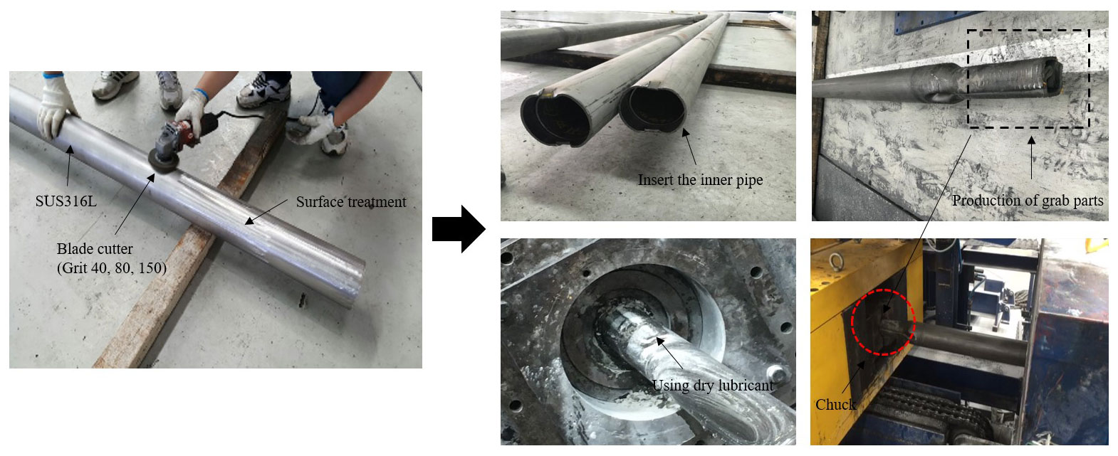
In order to measure the change in shear strength according to the surface roughness, three types of grinding treatment were performed outside the inner pipe. And then inserting the inner pipe whose surface treatment was completed into the outer pipe, a grab part was prepared for fastening to the chuck. The grab part is a part required for drawing the pipe which is attached to the front chuck. A double-layered pipe was placed on the die, and the plug was inserted inside the pipe. Dry lubricant was used as the lubrication condition. This is shown in Fig. 8.
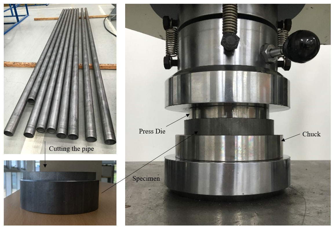
In this experiment, as shown in Fig. 9, specimens subjected to four types of surface treatment were produced through a drawing process and cut through laser cutting at 20 cm intervals. A universal tester was used to test the shear strength. The test was carried out at room temperature. The specimen was mounted on the lower jig, and the pressure was increased by 98 N/s (10 kgf/s) in the upper jig. The load was measured when the outer pipe and the inner pipe were separated with increasing load.
6.1 Result of surface roughness measurement
The average surface roughness of specimen surface-treated with grit blades 40, 80 and 150 is 2.817, 1.42 and 1.13, respectively, and the average surface roughness of the untreated specimen (virgin) is 1.93, as shown in Fig. 10. The surface roughness treated with the largest particle size (grit) value of 40 showed roughly twice the roughness treated with 80 and 2.5 times larger than the specimen treated with 150. In contrast, virgin specimens without surface treatment showed a value of about 1.45 times compare to the grit 40 specimen. The total results of the surface roughness are plotted in a graph in Fig. 11. The surface roughness tended to increase as the grinder blade increased from grit 40 to grit 150. These results suggest that specimens surface-treated with grit 40 blade will be the most favorable for the material penetration phenomenon; therefore it was expected to show the highest bonding strength.
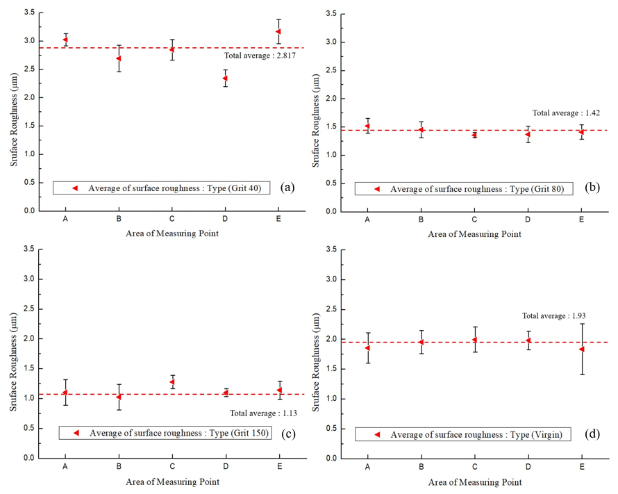
Figure 10Result of average surface roughness of each condition. (a) Grit 40, (b) grit 80, (c) grit 150 and (d) virgin.

6.2 Result of FEM analysis
The bonding mechanism occurs due to a phenomenon of the relatively high-strength material among two materials penetrating into the low-strength material. Therefore, among the outer pipe and inner pipe, material penetration occurs when the inner pipe is a low-strength material. Since the shear strength of the material is closely related to the penetration phenomenon, the pressure at the contact surface of the inner pipe was measured, and this is shown in Fig. 12a. The optimal friction coefficient that can promote the penetration phenomenon of the material can be found by measuring the normal pressure of the bonding surface of the two materials. In order to measure the pressure loaded on the bearing area in the drawing process of the double-layered pipe, analysis was conducted for a total of 800 steps in the normal drawing state, and the pressure was measured at five sample points at 300, 400 and 500 steps, and this is shown in Fig. 12b.
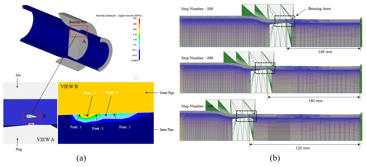
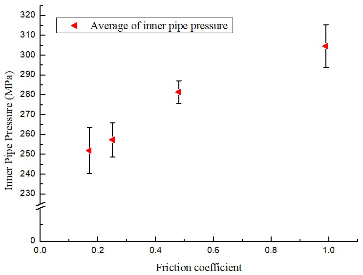
Figure 13 shows the result of FEM analysis, which has applied the Coulomb friction coefficient, derived by measuring the surface roughness after grinding the outside of inner pipe. When the friction coefficients were 0.17, 0.25, 0.48 and 0.99, the average values of inner pipe pressure were 251.93, 257.37, 281.5 and 304.63 MPa, respectively. The pressures loaded on the bonding surfaces of two materials all exhibited an increasing trend as the friction coefficient increased. The FEM analysis result based on the changes in friction coefficient showed that as the surface roughness increased, the inner pipe pressure increased.
6.3 Result of shearing test
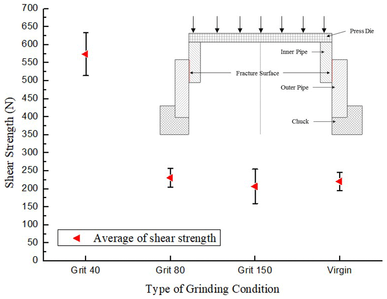
The results of the shear strength test are shown in Fig. 14. The test was conducted a total of 12 times using three specimens fabricated with four different surface conditions. The maximum shear strength of 574 N was measured on a specimen treated with a grit 40 blade, and a minimum shear strength of 207 N was measured on a specimen treated with a grit 150 blade. The average values of shear strength of the grit 80 and virgin specimens were 231 and 220.7 N, respectively. The surface roughness of the grit 40 specimen that exhibited the maximum shear strength was 2.8 on average, which was 2.47 times larger than the surface roughness of the grit 150 specimen.
To investigate the effect of surface roughness between two interfaces on the shear strength in the drawing process of the double-layered pipe, the surface treatment was performed using the grinder on the surface of the inner pipe. Furthermore, the surface roughness of the specimen that had finished the surface treatment was measured and converted into a Coulomb friction coefficient to be applied in a FEM analysis. The result of the shear strength test and FEM analysis that utilized the friction coefficient is as follows.
The surface roughness of specimens that were surface-treated using the grinder (grit 40, 80 and 150) was 2.8, 1.42 and 1.13 µm, respectively, and that of the virgin specimen was 1.93 µm. Coulomb friction coefficients obtained according to the experimental equation for the measured surface roughness (grit 40, 80, 150 and virgin) were 0.99, 0.17, 0.25 and 0.48, respectively.
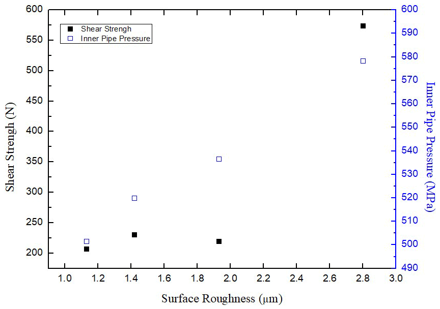
The total pressure results using FEM analysis and the result of shear strength tests using a UTM (universal testing machine) are shown in Fig. 15. The Coulomb friction coefficient derived by substituting the surface roughness measured through the experiment into Eq. (1) was applied in FEM analysis to calculate the normal pressure of the inner pipe surface. When the friction coefficients are 0.17, 0.25, 0.48 and 0.99, respectively, the average pressure on the inner pipe contact surface is 501.66, 519.9, 536.5 and 578.31, and the average shear strength is 207, 231, 220 and 574. As the surface roughness increased, the inner pipe pressure as a result of FEM analysis showed a tendency to increase continuously, However, the shear strength did not change below 1.93 µm and showed a tendency to increase rapidly from above 1.93 µm.
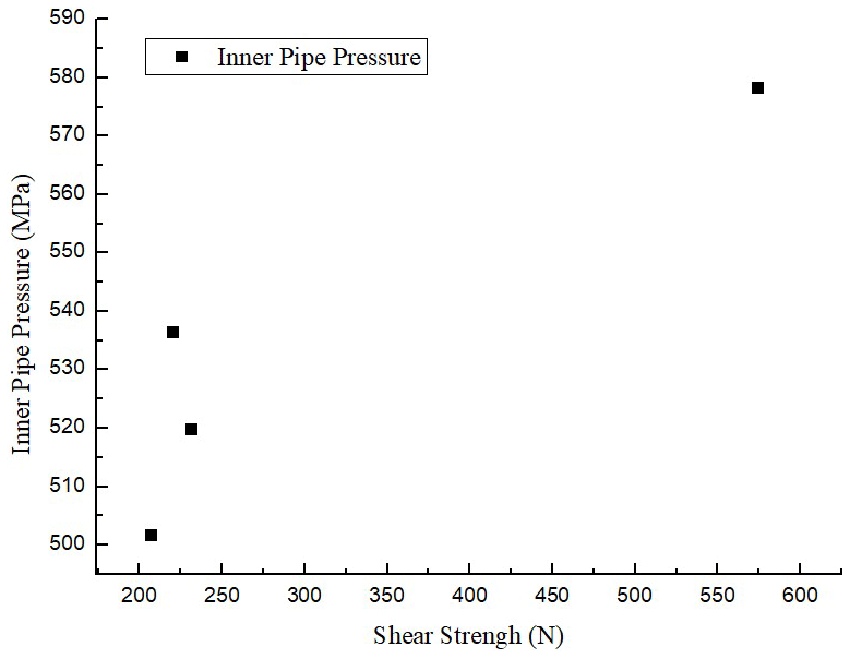
In summary, the shear strength of the two materials and the pressure acting between them are shown in Fig. 16. In the sections where the total pressure increased to 501.65, 519.9 and 536.53 MPa, the shear strength was 231, 207 and 220 N, respectively, thus not showing any significant change. Furthermore, the strength of the specimens that had been surface-treated with the grit 150 grinding blade was 11 N lower than that of the specimens that had not been surface-treated. Based on the above results, in the range of surface roughness from 1.13 to 1.93, there is no penetration between the materials, and therefore the shear strength is not affected. Therefore, the pressure acting between the two materials should be at least 570 MPa to ensure a shear strength of 500 N or higher, according to the material penetration phenomenon.
In this paper, through FEM analysis and a shear strength experiment, the bonding properties of two materials were studied according to the interface friction characteristics in the double-layered pipe drawing process, and the following conclusions were obtained.
The grinding of surfaces to be bonded can improve the double-layered pipe; thus, it may be reasonable to conclude that surface roughness is an important factor affecting shear strength.
When the surface roughness was not enough to reach a critical value, shear strength did not increase because the phenomenon that the high-strength outer material penetrates into the inner material did not occur. Therefore, in order to increase the shear strength, surface roughness exceeds a critical value.
As a result of FEM analysis by converting the surface roughness into the friction coefficient, the vertical pressure loaded on the inner pipe surface was increased when the friction coefficient was higher.
All in all, the feasibility of the cold drawing process to produce double-layered pipes was proved. The benefits of this process compared to cold roll bonding include preventing the decreased strength of welding area and the productivity. Through FEM analysis, the critical pressure value that the shear strength rapidly increases was derived.
Code is not publicly accessible.
All the data used in this paper can be obtained from the corresponding author upon request.
MA performed the analysis modeling and the experiments and edited the original draft. JP was responsible for the conceptualization, methodology, analysis of the experimental results and revision of the paper.
The authors declare that they have no conflict of interest.
This paper was supported by the Korea Institute for Advancement of Technology (KIAT) grant funded by the Korea Government (MOTIE) (P0002092, The Competency Development Program for Industry Specialist).
This paper was edited by Jeong Hoon Ko and reviewed by two anonymous referees.
Akdesir, M., Zhou, D., Foadian, F., and Palkowski, H.: Study of Different Surface Pre-treatment Methods on Bonding Strength of Multilayer Aluminum Alloys/Steel Clad Material, IJOER, 2, 169–177, 2016.
Akramifard, H. R., Mirzadeh, H., and Parsa, M. H.: Cladding of aluminium on AISI304L stainless steel by cold roll bonding: Mechanism, microstructure, and mechanical properties, Mat. Sci. Eng. A-Struct., 613, 232–239, https://doi.org/10.1016/j.msea.2014.06.109, 2014.
Eizadjou, M., Manesh, H. D., and Janghorban, K.: Investigation of roll bonding between aluminum alloy strips, Materials and Design, 29, 909–913, https://doi.org/10.1016/j.matdes.2007.03.020, 2008.
Eizadjou, M., Manesh, H. D., and Janghorban, K.: Mechanism of warm and cold roll bonding of aluminum alloy strips, Materials and Design, 30, 4156–4161, https://doi.org/10.1016/j.matdes.2009.04.036, 2009.
Fu, A. Q., Kuang, X. R., Han, Y., Lu, C. H., Bai, Z. Q., Yin, C. X., Miao, J., Feng, Y. R., Wei, Y. G., Tang, Q., and Yang, Y.: Failure analysis of girth weld cracking of mechanically lined pipe used in gasfield gathering system, Eng. Fail. Anal., 68, 64–75, https://doi.org/10.1016/j.engfailanal.2016.05.034, 2016.
Hosseini, M. and Manesh, H. D.: Bond strength optimization of clad composites produced by roll-bonding, Materials and Design, 81, 122–132, https://doi.org/10.1016/j.matdes.2015.05.010, 2015.
Jamaati, R. and Toroghinejad, M. R.: Manufacturing of high-strength aluminum/alumina composite by accumulative roll bonding, Mat. Sci. Eng. A-Struct., 527, 4146–4151, https://doi.org/10.1016/j.msea.2010.03.070, 2010.
Karnezis, P. and Farrugia, D. C. J.: Study of cold tube drawing by finite-element modelling, J. Mater. Process. Tech., 80–81, 690–694, https://doi.org/10.1016/S0924-0136(98)00127-7, 1998.
Lee, B. H., Keum, Y. T., and Wagoner, R. H.: Modeling of the friction caused by lubrication and surface roughness in sheet metal forming, J. Mater. Process. Tech., 130–131, 60–63, https://doi.org/10.1016/S0924-0136(02)00784-7, 2002.
Li, L., Nagai, K., and Yin, F.: Progress in cold roll bonding of metals, Sci. Technol. Adv. Mat., 9, 023001, https://doi.org/10.1088/1468-6996/9/2/023001, 2008.
Madaah-Hosseini, H. R. and Kokabi, A. H.: Cold roll bonding of 5754-aluminum strips, Mater. Sci. Eng., A335, 186–190, https://doi.org/10.1016/S0921-5093(01)01925-6, 2002.
Naseri, M., Reihanian, M., and Borhani, E.: Bonding behavior during cold roll-cladding of tri-layered Al/brass/Al composite, J. Manuf. Process., 24, 125–137, https://doi.org/10.1016/j.jmapro.2016.08.008, 2016.
Neves, F. O., Button, S. T., Caminaga, C., and Gentile, F. C.: Numerical and Experimental Analysis of Tube Drawing with Fixed Plug, J. Braz. Soc. Mech. Sci., 27, 426–431, https://doi.org/10.1590/S1678-58782005000400011, 2005.
Palengat, M., Chagnon, G., Favier, D., Louche, H., Linardon, C., and Plaideau, C.: Cold drawing of 316L stainless steel thin-walled tubes: experiments and finite element analysis, Int. J. Mech. Sci., 70, 69–78, https://doi.org/10.1016/j.ijmecsci.2013.02.003, 2013.
Rezaii, A., Shafiei , E., Ostovan, F., and Daneshmanesh, H.: Experimental & theoretical investigation of roll bonding process of multilayer strips by finite element method, J. Manuf. Process., 54, 54–69, https://doi.org/10.1016/j.jmapro.2020.02.044, 2020.
Vasilikis, D. and Karamanos, S. A.: Mechanical behavior and wrinkling of lined pipes, Int. J. Solids Struct., 49, 3432–3446, https://doi.org/10.1016/j.ijsolstr.2012.07.023, 2012.
- Abstract
- Introduction
- Theoretical background
- Surface roughness measurement and calculation of the friction coefficient
- FEM analysis
- Shear strength test
- Result and discussion
- Conclusion
- Code availability
- Data availability
- Author contributions
- Competing interests
- Financial support
- Review statement
- References